

Hobart Food Machines 6614 Installation Manual

MODEL 6614 MEAT SAW
MODEL
6614 ML-134096
PREVIOUS MODELS COVERED BY THIS MANUAL:
6614 ML-134050
701 S. RIDGE AVENUE
TROY, OHIO 45374-0001
937 332-3000
www.hobartcorp.com
FORM 34527 Rev. B (August 2011)
Installation, Operation, and Care of
MODEL 6614 MEAT SAW
SAVE THESE INSTRUCTIONS
GENERAL
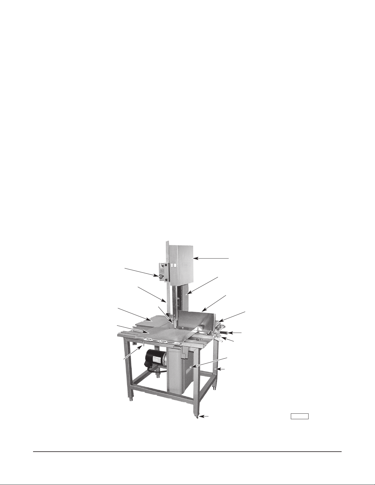
The 6614 Meat Saw is rugged, durable, and easy to clean. The saw is equipped with a water resistant
3 HP electric motor and direct gear drive transmission that provides a blade speed of 3500 feet per minute.
The carriage (Fig. 1) has stainless steel ball bearings providing easy travel and dependability. The shaped
front edge of the carriage is comfortable to the operator's body even when leaned on during movement.
The carriage lock is standard. The upper pulley cover and bafe are stainless steel.
Table, carriage, pulleys, guides, and wiper assemblies can be quickly removed without tools for ease of
cleaning. Moving parts are enclosed but accessible. The blade is guarded above and below the cutting
zone. The pusher plate is provided to eliminate the need of handling items close to the blade; it can ride
on the right "anged-end" of the carriage so you keep your hands away from the cutting edge of the blade.
For electrical specications above 250 volts, a transformer provides a 115 volt control circuit voltage.
One long-life blade is furnished with each saw as standard equipment. This blade cannot be re-sharpened;
replacement blades are available through your local Hobart Service Ofce.
SWITCH KNOB
UPPER GUIDE AND GUARD
TABLE (LEFT)
CARRIAGE
CARRIAGE LOCK
SAW BLADE
Fig. 1
UPPER PULLEYCOVER
COLUMN GUARD
GAUGE PLATE
LOWER COVER (SCRAP PA N)
LEGS
FEET
TABLE (RIGHT)
GAUGE PLATE HANDLE
LOCK LEVER
PL-41501-1
© HOBART, 1995, 2000
– 2 –
INSTALLATION
PL-52107
Hand Knob
Upper Guide
and Guard
UNPACKING AND ASSEMBLY
Immediately after unpacking the meat saw, check for possible shipping damage. If the meat saw is found
to be damaged, save the packaging material and contact the carrier within 15 days of delivery.
Prior to installation, test the electrical service to make sure it agrees with the specications on the machine
data plate located on the column.
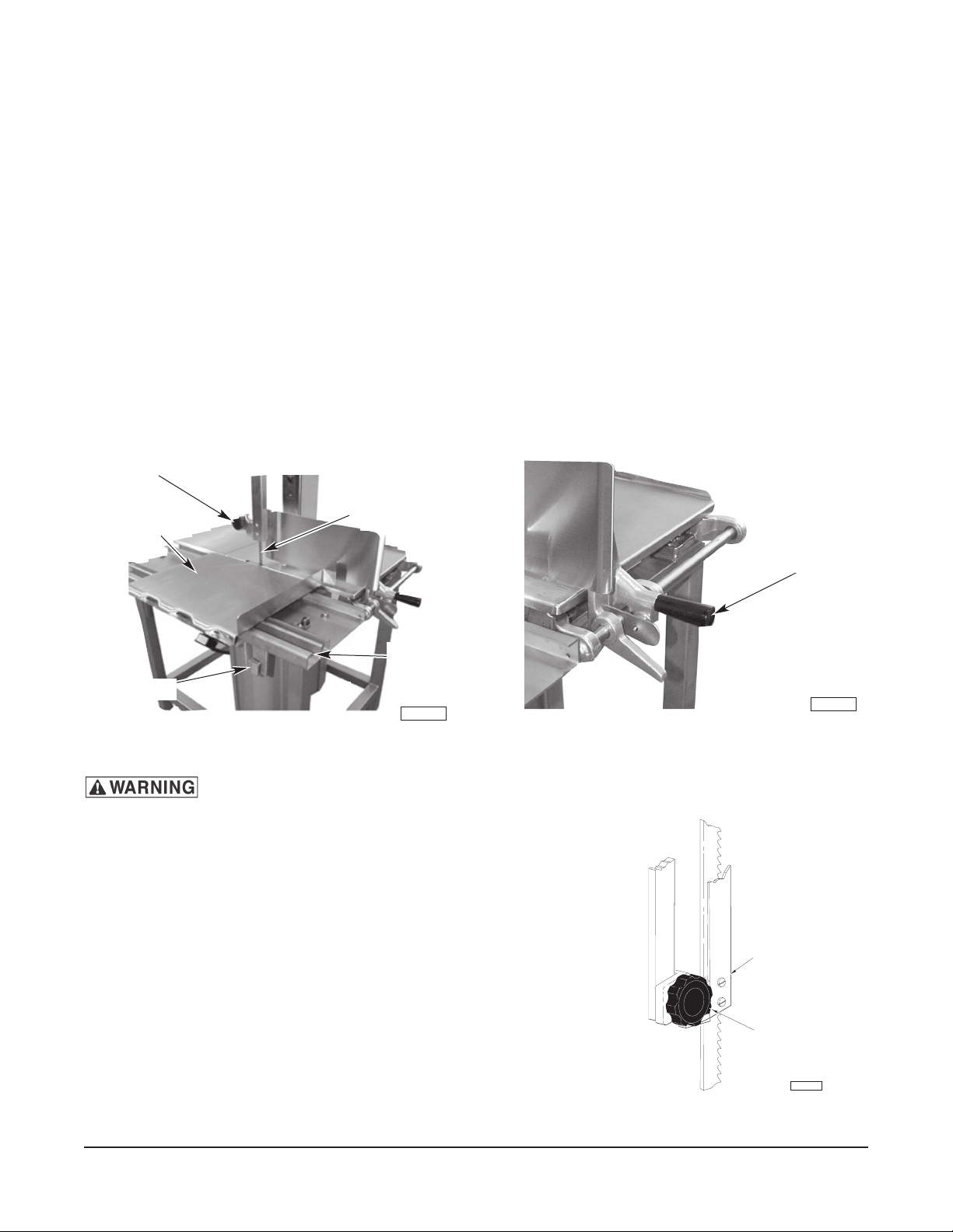
Packed in a packet attached to the table compartment are the pusher plate and the gauge plate handle.
Place the pusher plate in its storage location under the carriage support (Fig. 2). Assemble the gauge
plate handle to the gauge plate support by screwing the stud into the threaded hole (Fig. 3).
LEVELING
Place the saw in its operating location. Using a spirit level, level the meat saw front-to-back and side-toside by turning the threaded feet in or out.
HAND KNOB
SAW BLADE
CARRIAGE
CARRIAGE
SUPPORT
PUSHER PLATE
PL-41502-1
Fig. 2 Fig. 3
Disconnect the electrical power to the machine and follow lockout / tagout
procedures.
SAW BLADE
The saw blade must be installed so the teeth point to the right
and down (Fig. 4).
UPPER GUIDE AND GUARD ASSEMBLY
When the saw is off, the hand knob (Fig. 4) can be used to raise
or lower the upper guide and guard assembly so the cutting
zone is only as high as necessary for the piece being cut. The
hand knob is not loosened during raising or lowering — it should
remain tightly secure.
GAUGE PLATE HANDLE
PL-41503-1
Fig. 4
– 3 –
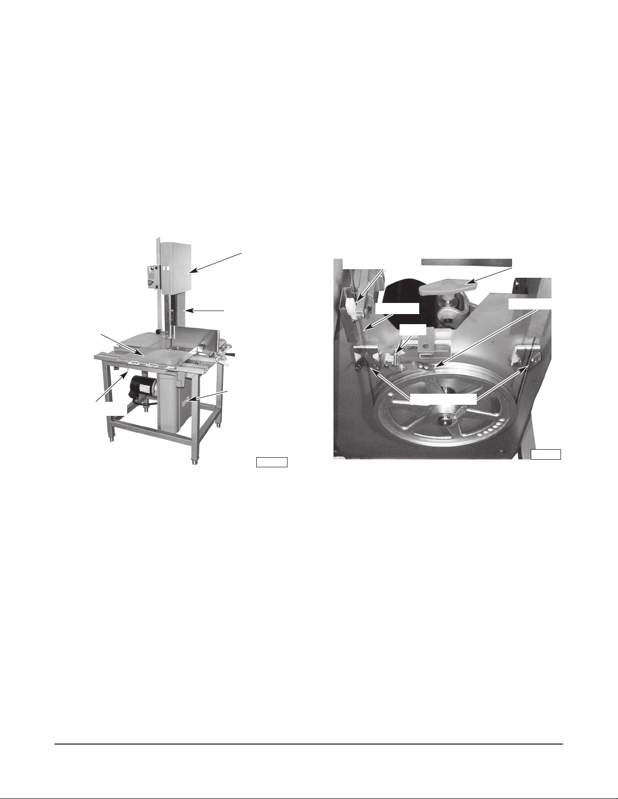
UPPER PULLEY COVER (STAINLESS STEEL)
The stainless steel upper pulley cover (Fig. 5) should be installed on the two hinge pins of the stainless
steel upper pulley bafe and securely latched during saw use. To remove the stainless steel upper pulley
cover for cleaning, unlatch and open the stainless steel upper pulley cover; then, lift straight up off the
hinge pins.
LOWER COVER (SCRAP PAN)
During use, the lower cover (Fig. 5) acts as a scrap pan, accumulating bone dust and debris from the
blade scrapers and pulley wiper that are located on the lower panel (Fig. 6). To remove the lower cover
(scrap pan) for cleaning, release the clip at the top; pull out and lift the lower cover from the groove at the
bottom of the lower panel.
UPPER PULLEYCOVER
LOWER BLADE GUIDE
TENSION
ADJUSTER
PULLEY WIPER
PL-41505-1
CARRIAGE
CARRIAGE LOCK
COLUMN GUARD
LOWER COVER
(SCRAP PAN)
PL--41504-1
Fig. 5 Fig. 6
SAW BLADE
BLOCK
BLADE SCRAPERS
BLADE SCRAPERS
Two blade scrapers wipe the blade during sawing to accumulate bone dust and debris inside the lower
cover (scrap pan). The front scraper points up and the rear scraper points down (Fig. 6). After the blade
is removed, the scrapers can slide off their mounting blocks for cleaning.
PULLEY WIPER
The pulley wiper (Fig. 6) scrapes bone dust or debris from the lower pulley during use. The pulley wiper
can be removed for cleaning by springing the wiper up and sliding it off the pins.
– 4 –
 Loading...