

Page 1

Administration Guide
HOBLink VPN Gateway
Software version: 2.1
Issue: November 2014
Page 2

HOBLink VPN Gateway Software and Documentation - Legal Notice
Contact: HOB GmbH & Co. KG
Schwadermuehlstr. 3
90556 Cadolzburg
Represented by: Klaus Brandstätter, Zoran Adamovic
Phone: + 49 9103 715 0
Fax: + 49 9103 715 271
E-mail: marketing@hob.de
Register of Companies: Entered in the Registry of Companies, Registry Court: Amtsgericht Fürth, Registration Number:
HRA 5180
Tax ID: Sales Tax Identification Number according to Section 27a Sales Tax Act: DE 132 747 002
Responsible for content according to Section 55 Paragraph 2 Interstate Broadcasting Agreement: Klaus Brandstätter,
Zoran Adamovic, Schwadermuehlstr. 3, 90556 Cadolzburg.
Disclaimer
All rights are reserved. Reproduction of editorial or pictorial contents without express permission is prohibited. HOBLink VPN
Gateway software and documentation have been tested and reviewed. Nevertheless, HOB will not be liable for any loss or
damage whatsoever arising from the use of any information or particulars in, or any error in, or omission from this document.
All information in this document is subject to change without notice, and does not represent a commitment on the part of HOB.
Liability for content
The contents of this publication were created with great care and diligence. While we keep it as up-to-date as practicable, we
cannot take any responsibility for the accuracy and completeness of the contents of this publication. As a service provider we
are responsible for our own content in this publication under the general laws according to Section 7 paragraph 1 of the TMG.
According to Chapters 8 to 10 of the TMG we are not obliged as a service provider to monitor transmitted or stored information
not created by us, or to investigate circumstances that indicate illegal activity. Obligations to remove or block the use of
information under the general laws remain unaffected. Liability is only possible however from the date of a specific
infringement being made known to us. Upon notification of such violations, the content will be removed immediately.
Liability for links
This publication may contain links to external websites over which we have no control. Therefore we cannot accept any
responsibility for their content. The respective provider or operator of the website pages to which there are links is always
responsible for the content of the linked pages. The linked sites were checked at the time of linking for possible violations of
the law. At the time the link was created in this publication, no illegal or harmful contents had been identified. A continuous
and on-going examination of the linked pages is unreasonable without concrete evidence of a violation. Upon notification of
any violations, such links will be removed immediately.
Copyright
The contents and works on these pages created by the author are subject to German copyright law. Reproducing, copying,
modifying, adapting, distributing or any kind of exploiting of this material outside the realms of copyright require the prior
written consent of the respective author or creator. The downloading of, and making copies of, these materials is only
permitted for private, non-commercial use. Where contents of this publication have not been created by the author, the
copyright of the third parties responsible for these contents shall be upheld. In particular any contents created by a third party
are marked as such. If you become aware of any copyright infringement within this publication, we kindly ask to be provided
with this information. Upon notification of any such violation,
Trademarks
Microsoft Windows is a trademark of Microsoft Corporation.
Linux® is the registered trademark of Linux Torvalds in the U.S. and other countries.
UNIX is a registered trademark of The Open Group.
Mac OS and Apple are trademarks of Apple Inc., registered in the U.S. and other countries.
Oracle and Java are registered trademarks of Oracle and/or its affiliates.
All other product names, company names and service names may be trademarks, registered trademarks or service marks of
their respective corporations or owners, even if they are not specifically marked as such.
the concerned content will be removed immediately.
Issued: November 28, 2014
2 Security Solutions by HOB
Page 3

Purpose of this Guide
This guide is designed to provide system administrators with detailed information
concerning HOBLink VPN Gateway and to help them decide where and when this product
can be most effectively deployed in their enterprise network.
This documentation contains descriptions of numerous possible scenarios and explains
required conditions. The procedures for configuring the individual software components are
documented in detail with step-by-step instructions.
Symbols and Conventions
This guide uses certain conventions and abbreviations which are explained here:
This symbol indicates useful tips that can make your work easier.
This symbol indicates additional informative text.
This symbol indicates an important tip or procedure that may have far-reaching
effects. Please consider carefully the consequences of any changes and settings
you make here.
References to program commands, options and buttons are printed in Bold, for example:
select the command Open.
Cross-references to section headings and figures with numbers are marked in color as
follows: Section 5 Information and Support.
File names and text to be entered by the user are printed in Courier New. This input is
– unless otherwise mentioned - case sensitive.
In this documentation, HOB-specific terminology is abbreviated as follows:
HOB-specific Terminology Abbreviation
HOBLink Virtual Private Network HOBLink VPN
Other abbreviations commonly used in this documentation are as follows:
Full Name Abbreviation
Internet Protocol Security IPsec
Internet Key Exchange IKE
Network Addresss Translation NAT
Extensible Markup Language XML
Uniform Resource Locator URL
Graphical User Interface GUI
Transmission Control Protocol/Internet Protocol TCP/IP
Security Solutions by HOB 3
Page 4

Dead Peer Detection DPD
User Datagram Protocol UDP
Distinguished Name DN
Network TUNnel/Tap, the Virtual Network Device
Tun/Tap
Interface
Remote Desktop Protocol RDP
4 Security Solutions by HOB
Page 5

Contents
1 Introducing HOBLink VPN Gateway 7
1.1 Introducing Kanji............................................................................................. 7
1.2 Introducing VPN Peers and VPN Rules ......................................................... 7
1.3 Features of HOBLink VPN Gateway .............................................................. 7
1.4 Components of HOBLink VPN Gateway ........................................................ 9
2 Installing HOBLink VPN Gateway 13
2.1 Starting HOBLink VPN Gateway .................................................................. 13
2.2 Managing HOBLink VPN Gateway............................................................... 13
2.3 Requirements of HOBLink VPN Gateway .................................................... 14
3 Administering HOBLink VPN Gateway 15
3.1 HOB Portal ................................................................................................... 15
3.2 Administering HOBPortal.............................................................................. 16
3.3 Users ............................................................................................................ 17
3.4 Sessions....................................................................................................... 19
3.5 Portlets ......................................................................................................... 20
3.6 Using the HOB Portal ................................................................................... 22
4 Configuring the Kanji GUI Tool 25
4.1 Defining Paths for Kanji and XML files ......................................................... 26
4.2 Selecting Kanji and XML Filepaths from the Kanji Configuration ................. 27
5 Configuring HOBLink VPN Gateway 29
5.1 Properties ..................................................................................................... 29
5.2 Auditing ........................................................................................................ 31
5.3 Network ........................................................................................................ 33
5.4 Service.......................................................................................................... 34
5.5 Remote Authentication Dial In User Service (RADIUS) ............................... 35
5.6 Lightweight Directory Access Protocol (LDAP) ............................................ 37
5.7 Microsoft Layer 2 Tunneling Protocol (L2TP)............................................... 41
5.8 Internet Key Exchange (IKE)........................................................................ 42
5.9 Internet Protocol Security (IPsec)................................................................. 49
5.10 Users ............................................................................................................ 52
5.11 VPN .............................................................................................................. 54
5.12 VPN Gateway StatusInfo.............................................................................. 59
6 Configuring XML Parameters for HOBLink VPN Gateway 61
6.1 Configuration Parameters for Properties (properties)............................. 61
Security Solutions by HOB 5
Page 6

6.2 Configuration Parameters for Auditing (auditing) .....................................61
6.3 Configuration Parameters for Network (network) .......................................62
6.4 Configuration Parameters for Service (service) ........................................63
6.5 Configuration Parameters for RADIUS (radius)......................................... 64
6.6 Configuration Parameters for IKE (ike) .......................................................66
6.7 Configuration Parameters for IPsec (ipsec)................................................71
6.8 Configuration Parameters for Users (user) .................................................73
6.9 Configuration Parameters for VPN (vpn)......................................................74
6.10 Configuration Parameters for L2TP (l2tp) .................................................. 80
6.11 Configuration Parameters for LDAP (ldap) .................................................81
7 Information and Support 83
6 Security Solutions by HOB
Page 7

HOBLink VPN Gateway Introducing HOBLink VPN Gateway
1 Introducing HOBLink VPN Gateway
HOBLink Virtual Private Network Gateway (HOBLink VPN Gateway) is a VPN
gateway solution for access to your network data with strong and secure IKE/IPsec
encryption methods. It uses the IPsec, IKEv1 and IKEv2 protocols to give your
company the security you require. HOBLink VPN Gateway provides authenticity,
integrity and confidentiality checks for each stage of data transfer.
HOBLink VPN Gateway is a new implementation of an IPsec based VPN gateway
as a software solution. Versions for different products are provided and are primarily
available for Linux, BSD and Microsoft Windows platforms.
It is intended to support HOBLink VPN 1.8 clients and gateways, as well as other
RFC compliant solutions.
HOBLink VPN Gateway enables you to have secure, economical, reliable and
universal remote access to all your enterprise IT resources.
1.1 Introducing Kanji
Kanji is a GUI tool with a Java interface that is used to create and modify
configuration XML files. Kanji can be applied to many products. In this case, it is an
intuitive interface used in the HOB Portal that anyone is able to use to configure
VPN connections. See Section 3 Administering HOBLink VPN Gateway on page 15
for more information.
1.2 Introducing VPN Peers and VPN Rules
HOBLink VPN Gateway uses IPsec and IKE security encryption protocols. As these
do not allow a traditional client-server relationship, a system of peers is used to
avoid this problem. In a peer system there is no distinction between the participants
as with a client-server set up, with all devices being on the same peer level. A
system of rules is also used to govern how the peers within the VPN communicate
with each other.
How to set up the VPN Peers and the VPN Rules is described in Section
6.9 Configuration Parameters for VPN (vpn) on page 74. The other
components of the configuration consist of the information needed to fulfill
the requirements for setting up VPN Peers and VPN Rules.
1.3 Features of HOBLink VPN Gateway
HOBLink VPN Gateway is a gateway solution for access that uses these two
processes:
hobvpn2
hobsr
The process hobvpn2 runs in normal user space without any root or administrative
privileges on the computer. There are two reasons for this. Firstly, unlike most IPsec
VPNs that run in Kernel mode, if there is an error the operating system is not
involved, meaning there are no “blue screen” errors. Secondly, as the process is
Security Solutions by HOB 7
Page 8

Introducing HOBLink VPN Gateway HOBLink VPN Gateway
used for access over the public Internet, having no privileges means the process
cannot be used to access other parts of the computer in the event of an attack. This
is an extra security feature of this solution. Please note that hobvpn2 should be
started by a non-privileged user.
The second process, hobsr, is used for tasks that need root/administrator rights
(e.g. to open a RAW socket, to create or open the Tun/Tap device, creating static
routes and ProxyARP entries, etc.). This process is not accessible from the Internet,
providing only secure internal communication to hobvpn2. This process needs to
be provided with extra access rights and is started automatically by hobvpn2.
Other features and highlights of HOBLink VPN Gateway include:
Using state-of-the-art IPsec encryption technology and supporting strong
authentication, according to the IPsec RFCs 2401 ff.
Using multiple encryption methods such as AES128, AES192, AES256, 3DES,
Blowfish and CAST128.
Fully compatible with HOBLink VPN 1.6 and 1.8 gateways and clients, users and
user groups, as well as the IPsec products from many other vendors.
Using all IKE and IPsec standards and tunnel modes that were supported in
version 1, including IKEv1, AH, ESP, IPCOMP and their combinations (AH+ESP,
AH+IPCOMP, ESP+IPCOMP, AH+ESP+IPCOMP) to provide data manipulation
alerts and replay detection. This ensures that the data has not been corrupted.
IPsec processing takes advantage of multiple CPUs and can process several
packets concurrently. A special thread managing system optimizes the usage of
CPU and RAM resources.
The Tun/Tap interface is used to carry the IP packets from the kernel into user
space and vice versa.
IKEv1 supports two different types of Phase 1 negotiations, Main Mode and
Aggressive Mode. Aggressive Mode supports two additional authentication
methods, Hybrid and XAuth. IKE Phase 2 negotiations use Quick Mode.
IKE Phase 1 supports RADIUS and LDAP/AD authentication for clients.
IKE supports IKE Client Configuration Mode (for the assignment of virtual IPs
and primary and secondary DNS servers).
HOBLink VPN Gateway supports certificates (HOB CDB, Microsoft CryptoAPI).
HOBLink VPN Gateway supports Syslog auditing over UDP port 514.
HOBLink VPN Gateway includes NAT detection and NAT keepalives.
HOBLink VPN Gateway supports UDP encapsulation for NAT traversal.
HOBLink VPN Gateway supports DPD (Dead Peer Detection).
The VPN rules support the negation of the traffic selectors source, destination
and service.
HOBLink VPN Gateway supports XML configuration, with local configuration
files in XML format. SSL connections are also supported (https).
All services, ports and connections are fully configurable. Configuration is also
possible via a web browser, both local and remote.
8 Security Solutions by HOB
Page 9

HOBLink VPN Gateway Introducing HOBLink VPN Gateway
1.4 Components of HOBLink VPN Gateway
HOBLink VPN Gateway is a complete software solution that is delivered in a
modular form. These modules, both core modules and configuration modules, are
installed together and work together to provide the functionality you require.
1.4.1 Core Modules
There are two core modules that provide the required functionality of HOBLink VPN
Gateway. These are the:
Process Modules
Library Modules
Process Modules
The basic functionality of HOBLink VPN Gateway is provided by the process
hobvpn2 (main process). An important process, hobsr, provides hobvpn2 with
added system resources and therefore needs special root permissions.
Another process, sendsig, sends two signals to the hobvpn2 process. These
signals provide the following tasks:
sendsig (sent without any parameter) - this signal indicates to the hobvpn2
process that the configuration has been changed while the VPN is still running.
The hobvpn2 process then reads the configuration file again and updates its internal processes accordingly, while it continues running.
sendsig hobvpn2 - this forces the hobvpn2 process to stop running
Library Modules
Some libraries are needed for a proper connection:
libgcc_s.so.1
libhobxcw3.so
libhvpnintf32.so
libstdc++.so.6.0.14 (this has a link called libstdc++.so.6).
1.4.2 Configuration Modules
The configuration modules are the files that contain the necessary data needed by
HOBLink VPN Gateway to fulfill the tasks required of it.
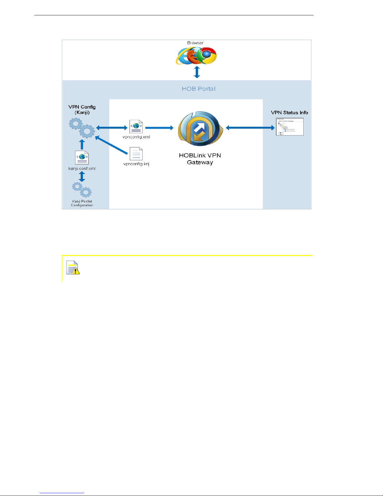
vpnconfig.xml – this file contains the configuration data that
HOBLink VPN Gateway needs to establish IKE/IPsec connections. It is located
in the installation folder /HOB/HOBLinkVPN of the application. For configuration
purposes, this file may either be edited directly or via a browser (either locally or
remotely), in which case the configuration server must be correctly configured.
See Section 3 Administering HOBLink VPN Gateway on page 15 for more
information.
Security Solutions by HOB 9
Page 10
Introducing HOBLink VPN Gateway HOBLink VPN Gateway
Figure 1: Standard Browser-based Configuration Scheme
vpnconfig.knj – this file contains data describing the structural elements of
the HOBLink VPN Gateway configuration. It is used by the HOB configuration
server to create the HTML pages for the browser during configuration.
It is strongly recommended to always leave this file, vpnconfig.knj,
unchanged.
The browser-based configuration and retrieval of status information is managed by
the HOB Portal system. This is installed in the folder HOBPortal which is found in
the HOB folder of the installation.
A standard TCP/IP connection from the Java-capable web browser is used to
connect to the HOB Portal server, please see Section 3.1 HOB Portal on page 15
for more information.
1.4.3 Certificate Support Modules
Certificates are used to authenticate the machines responsible for communication.
The modules that contain these certificates are located in the installation folder of
HOBLink VPN Gateway. This folder contains a sub-folder, cert.db, containing two
files:
vpn.cdb - a HOB certificate database file
vpn.pwd - a password file
10 Security Solutions by HOB
Page 11

HOBLink VPN Gateway Introducing HOBLink VPN Gateway
The certificates provided in this HOB keystore vpn.cdb are intended for
testing and demo purposes only. It is strongly recommended that for
productive day-to-day operations you remove these vpn.cdb and
vpn.pwd files and create your own keystore and password files. Use the
HOBLink Security Manager to either create your own PKI or just add the
available certificates to your own keystore.
These files can be edited via the HOBLink Security Manager tool, which
is delivered on CD for extra installation. Documentation concerning the
HOBLink Security Manager is available after the installation of this HOB
tool.
Security Solutions by HOB 11
Page 12

Introducing HOBLink VPN Gateway HOBLink VPN Gateway
12 Security Solutions by HOB
Page 13

HOBLink VPN Gateway Installing HOBLink VPN Gateway
2 Installing HOBLink VPN Gateway
The HOBLink VPN Gateway software is provided in a compressed file that is
installed using an install script. The compressed file is hob-vpn2-gw.tar.bz2
and the install script is installVPN2-GW.sh.
To install HOBLinkVPN Gateway for Linux:
1. Log on as Root User in your Linux system.
2. From the command line, run the install script installVPN2-GW.sh.
3. Select where to install the software (this will be /opt/HOB/ by default).
4. Select the option to start VPN2GW and HOBPortal (this step is optional).
Once the software has been installed, make sure that IP Forwarding is enabled. If
it is not enabled, run the script enableIPForwarding.sh located in the HOB
folder. To disable it again, run the script disableIPForwarding.sh.
2.1 Starting HOBLink VPN Gateway
When the software is installed via the install script, HOBLink VPN Gateway can
either be started in Step 2 below or started later.
To start HOBLink VPN Gateway:
1. Log on to the system as a normal user.
2. From the command line, run the script startVPN.sh located in the HOB folder.
This starts the hobvpn2 process, giving the parameter -c vpnconfig.xml for the
configuration file, as a daemon.
The script startVPN2-GW.sh can also be used to start HOBLink VPN Gateway,
which in turn also starts the HOBPortal server.
For debugging purposes:
The process hobvpn2 accepts the following parameters:
-a – this step is optional. This runs hobvpn2 as an application. If this is not
already specified, hobvpn2 runs as a daemon (in the background) instead.
-c (config file) – this step is optional. If this is not present, then the config.xml
file is used as default.
2.2 Managing HOBLink VPN Gateway
The following information refers to the installation folder, which is /opt/HOB/
HOBLinkVPN/ by default. The administration scripts are in the HOB installation
folder (in this case, /opt/HOB/).
The command ./hobvpn2 -c vpnconfig.xml starts the VPN process, where
the parameter -c indicates the name of the configuration file (vpnconfig.xml by
default). A normal, non-privileged user should start the process. It is easier to start
the VPN process by running the script startVPN.sh, which runs the provided
command.
Security Solutions by HOB 13
Page 14

Installing HOBLink VPN Gateway HOBLink VPN Gateway
In order to stop the VPN process, run the script stopVPN.sh. This sends the
command ./sendsig hobvpn2 that orders the VPN process to stop working
gracefully.
To reload and implement changes in the configuration file, run the script
reloadConfig.sh
. This runs the process ./sendsig, which sends the
command to the VPN process to reload and implement the configuration file.
2.3 Requirements of HOBLink VPN Gateway
The following are the necessary minimum requirements for a successful installation
of HOBLink VPN Gateway:
System Requirements
HOBLink VPN Gateway is designed to run on the Linux operating system platform.
It requires only a standard Linux machine, with at least Kernel 2.6.x, including the
Tun/Tap interface.
HOBLink VPN Gateway supports both 32 and 64 bit systems.
Software Requirements
There are two options available for configuring HOBLink VPN Gateway:
a web browser
a standard or XML editor (for editing the configuration file)
For logging purposes:
Messages created while starting HOBLink VPN Gateway are written into the file
trace.txt which is located in the installation folder.
Messages created while running HOBLink VPN Gateway are to be logged by a
syslog server listening on UDP port 514. By default, the configuration file
vpnconfig.xml that is delivered with the solution contains a syslog server
configuration with the IP address 127.0.0.1, localhost.
14 Security Solutions by HOB
Page 15

HOBLink VPN Gateway Administering HOBLink VPN Gateway
3 Administering
HOBLink VPN Gateway
HOBLink VPN Gateway can be configured in two ways:
1. By manually setting the configuration parameters by editing the configuration
file vpnconfig.xml. The vpnconfig.xml file needs to be opened in a text
editor to edit the parameters as required.
Please refer to Section 6 Configuring XML Parameters for HOBLink VPN
Gateway on page 61 for a detailed description of the parameters.
2. By editing the file via the HOB Portal management interface in the browser.
When editing through a GUI, you need to connect locally to a web browser. The
following web browsers are supported:
Microsoft Internet Explorer - Versions 9,10,11
Firefox - Version 28
Google Chrome - Version 34
3.1 HOB Portal
HOB Portal is the interface for the browser connection to HOBLink VPN Gateway
over an IP-based network. This interface provides information about the gateway
and allows HOBLink VPN Gateway to be configured.
The installation folder of HOB Portal is /opt/HOB/HOBPortal/ by default.
The HOB Portal server should be started by the script startHOBPortal.sh,
which launches the command bin/startup.sh.
To stop the HOB Portal server, run the script stopHOBPortal.sh. This script
launches the command bin/shutdown.sh to stop the HOB Portal server.
3.1.1 Connecting to HOB Portal
To connect to HOB Portal locally, enter the following URL into a browser:
http://localhost:5822/
To connect to HOB Portal over the network, enter the URL using the
hostname as follows:
http://<hostname>:5822/
3.1.2 Connecting to HOB Portal over SSL
To create an SSL encrypted connection to HOB Portal, enter the URL:
https://<hostname>:8443 into your browser.
A Java keystore is delivered in the path .../HOBPortal/conf.
The relevant server setting is to be found in the file
.../HOBPortal/conf/server.xml, in line 87.
Security Solutions by HOB 15
Page 16
Administering HOBLink VPN Gateway HOBLink VPN Gateway
Here you can find the path and name of the keystore as well as the password, which
is hoblinkvpn by default.
3.1.3 Using your own SSL certificate
To use your own SSL certificate when connecting to HOB Portal, perform the
following steps:
1. Create your Java keystore containing a valid certificate.
2. Edit the file server.xml accordingly.
3. Launch the process .../HOB/stopHOBPortal.sh and then the process
.../HOB/startHOBPortal.sh in order to restart the HOBPortal server.
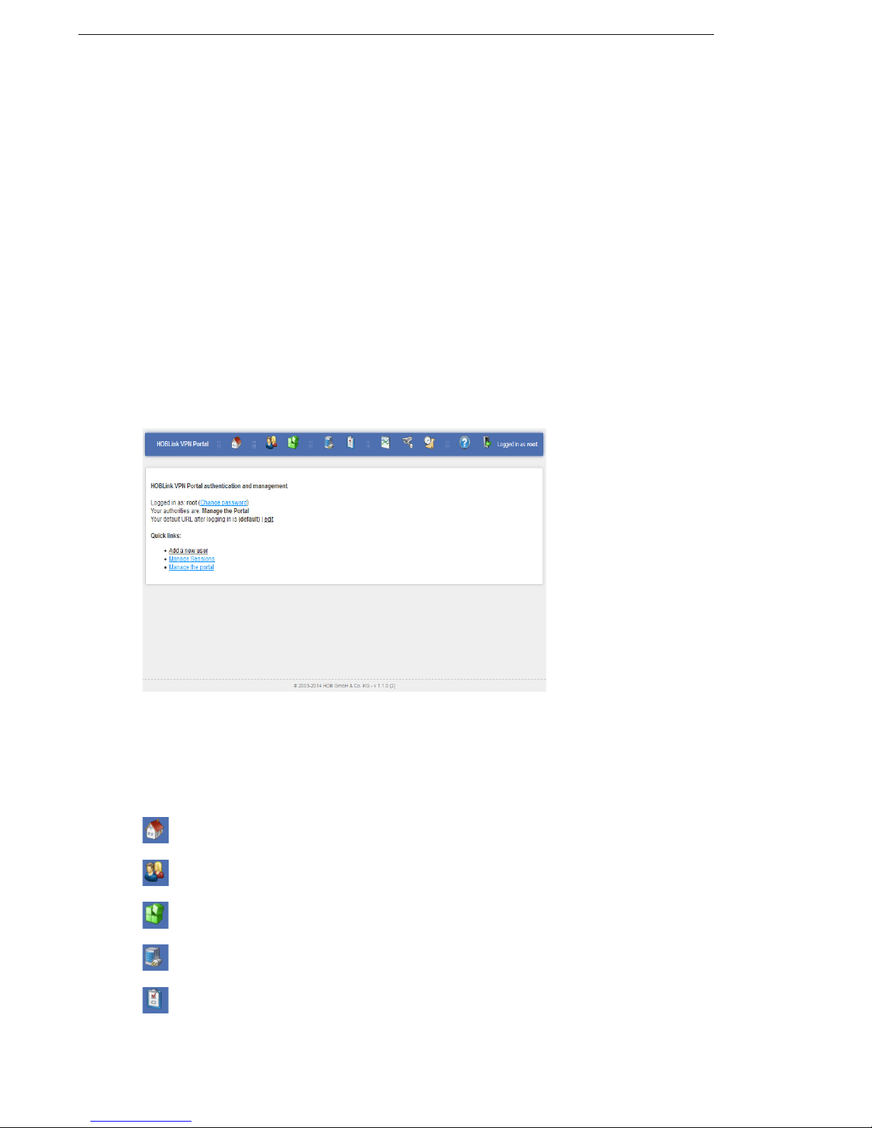
3.2 Administering HOBPortal
This set of screens is available to the root user or another user with the authority to
manage the portal of HOBLink VPN Gateway. Logon to HOBLink VPN Gateway
with the root user username and password. The following screen is displayed:
Figure 2: HOBLink VPN Portal
Information about the root user’s current status and permissions is provided here,
as well as the quick links Manage Sessions and Manage the portal that are
available to you. Only an administrator can use the quick link Add a new user. In
addition, the title bar has the following icons that are on every page of the portal:
Home – returns you to this start screen from anywhere within the application.
Users – accesses the manage users screen.
Portal configuration – displays the portlet and page administration screen.
Service – displays the current status of the service.
Properties – displays the system properties page.
16 Security Solutions by HOB
Page 17
HOBLink VPN Gateway Administering HOBLink VPN Gateway
Sessions – displays the manage sessions page. See Section 3.4 Sessions
on page 19 for more information.
Auditing – displays the audit logs on screen.
Logs – displays the system logs on screen.
Help – displays the help that is available for this application.
Logout – logs you out of the application and returns you to the main
HOBLink VPN Gateway portal.
3.3 Users
When you access the quick link Add a new user you will see this screen. Here you
can manage the users already configured in HOBLink VPN Gateway and add new
users to the user list.
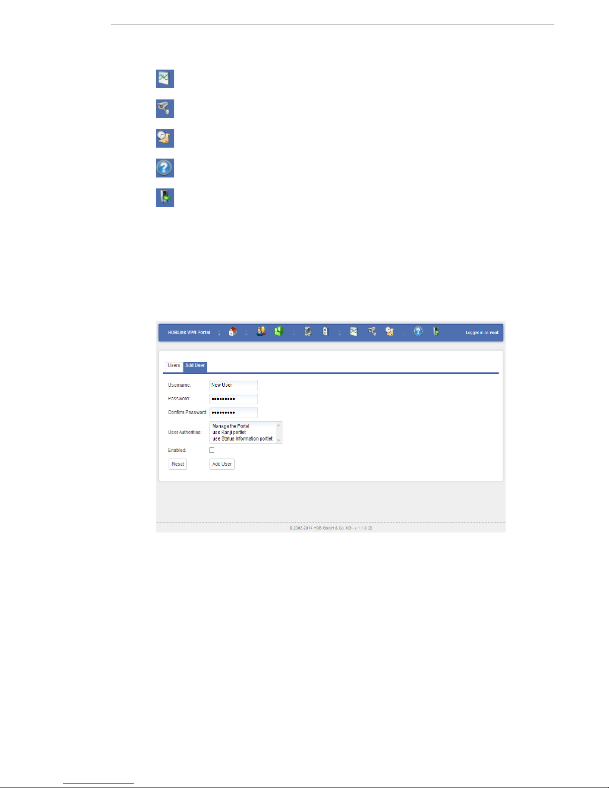
3.3.1 Add User
Figure 3: User
This tab allows you to add new the users to those that are already present in
HOBLink VPN Gateway. You need to complete the following fields:
Username - enter the name assigned to this user in the system
Password - enter the password for confirming the identity of this user
Confirm password - enter the password again to confirm
User authorities - select the permissions from this list of permissions available to
the user. It is possible to select several permissions.
Enabled - check this box to activate this user in the user list.
Security Solutions by HOB 17
Page 18
Administering HOBLink VPN Gateway HOBLink VPN Gateway
There are also two buttons:
click Reset to discard any edits and restore any previously entered
information to this page.
click Add user to save any changes and add the new user to the user list
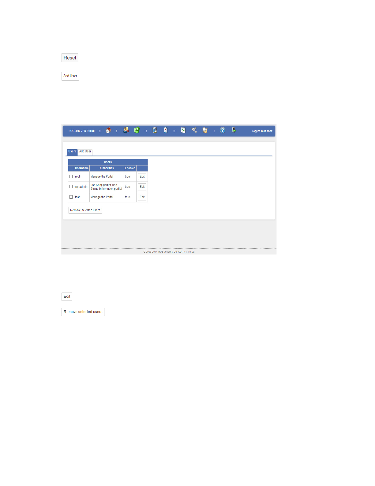
3.3.2 Users
The Users tab allows you to manage the already existing users. You will see this
screen:
Figure 4: Manage Users
In this list of users you select the user from the list. Use the Edit and the Remove
selected users buttons to manage selected users in the list.
use this button to edit the configuration of the selected user
this button deletes the selected user from the user list
18 Security Solutions by HOB
Page 19
HOBLink VPN Gateway Administering HOBLink VPN Gateway
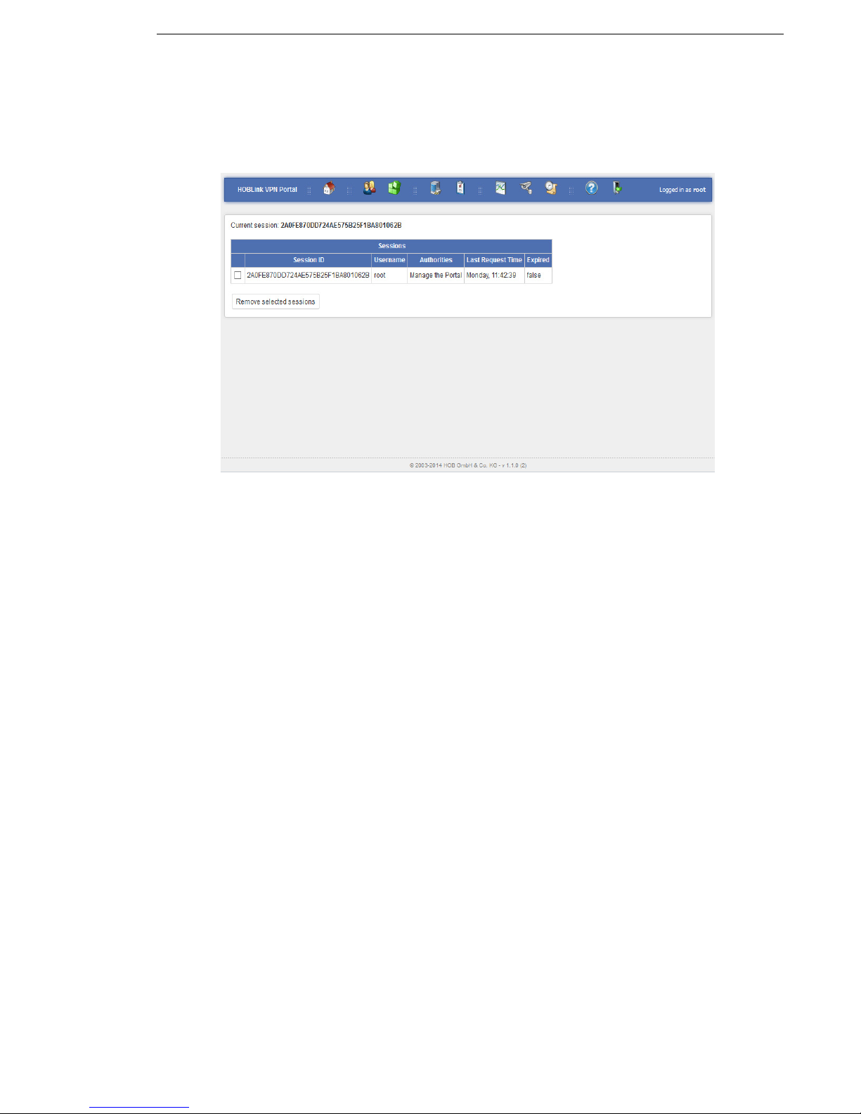
3.4 Sessions
When you access the quick link Manage sessions, you will see this screen. Here
you manage the sessions in HOBLink VPN Gateway.
Figure 5: Sessions
Sessions that are currently open are displayed in the list. Details of the sessions
such as username, authorities and last request time are shown. Sessions can be
deleted by selecting the sessions to be removed and then using the Remove
selected sessions button to remove them from this list.
Security Solutions by HOB 19
Page 20
Administering HOBLink VPN Gateway HOBLink VPN Gateway
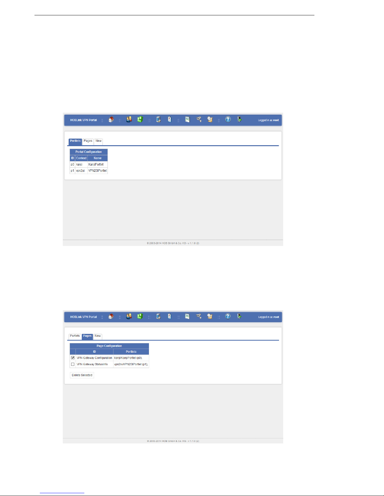
3.5 Portlets
When you access the quick link Manage the portal, you will see this screen. Here
you manage portlets and pages. There are three tabs on this interface: Portlets,
Pages and New.
3.5.1 Portlets
When the Portlets tab is selected, the following screen is displayed:
Figure 6: Manage Portlets
Here you see the portlets currently available for use in the pages (showing the ID
number, the context of the application and the name of each portlet).
3.5.2 Pages
Select the Pages tab to display the following screen where you manage pages.
Figure 7: Manage Pages
20 Security Solutions by HOB
Page 21
HOBLink VPN Gateway Administering HOBLink VPN Gateway
Here the page configurations are displayed. The ID for each page as well as the
portlets that are on each page are shown. If a page is to be deleted, select that page
and click the Delete Selected button to remove it.
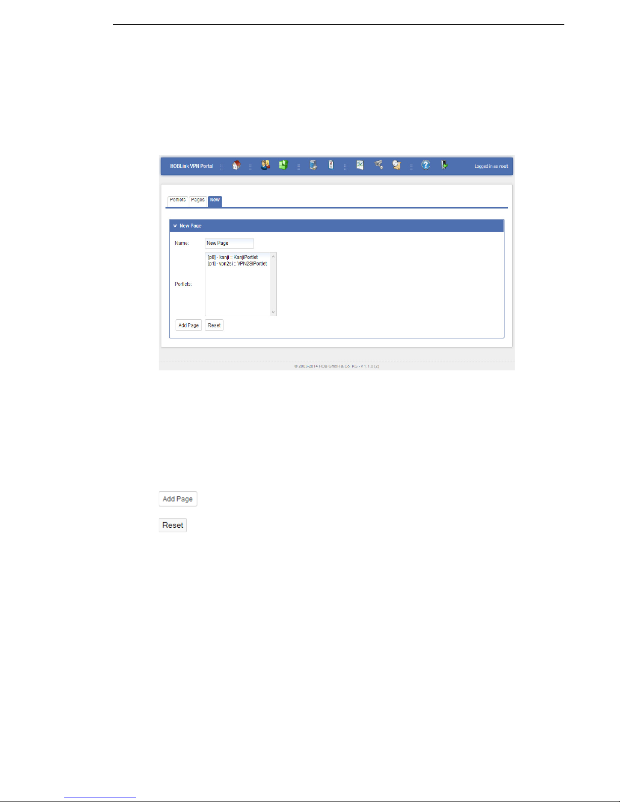
3.5.3 New
Select the New tab to display the following screen where you can create new pages.
Figure 8: Manage New Pages
For each new page you need to complete the following fields:
Name – enter a name for the new page.
Portlets – select from the list of existing portlets those that you wish to be included
on the new page.
Once you have finished entering the parameters, you have the following options:
click Add Page to create the new page.
click Reset to clear any previously entered information if you want to start
configuring the page.
Security Solutions by HOB 21
Page 22
Administering HOBLink VPN Gateway HOBLink VPN Gateway
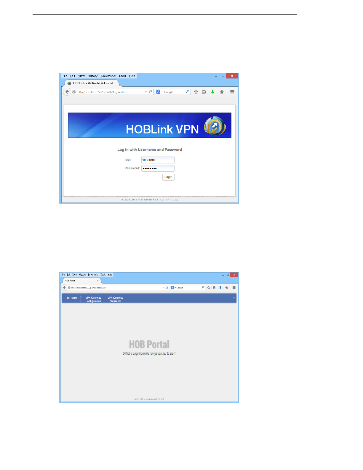
3.6 Using the HOB Portal
When the HOBLink VPN Gateway Logon screen is displayed, you will see this
screen:
Figure 9: Logon
Following the default installation, two default users are already configured:
root (password = root) – the administrator user for the HOB Portal.
vpnadmin (password = vpnadmin) – the VPN administrator user for
configuration and status information.
Log in as vpnadmin or root to display the HOB Portal.
Figure 10: HOB Portal
The HOB Portal provides two portlets:
22 Security Solutions by HOB
Page 23

HOBLink VPN Gateway Administering HOBLink VPN Gateway
Kanji – the configuration tool (see Section 4 Configuring the Kanji GUI Tool on
page 25 for more information on this topic).
VPN2 SI – this gives the current status information about the VPN gateway.
These portlets are configured in the HOB Portal pages. By default, the HOB Portal
consists of two pages:
VPN Gateway Configuration – see Section 5 Configuring HOBLink VPN
Gateway on page 29 for more information.
VPN Gateway StatusInfo – see Section 5.12 VPN Gateway StatusInfo on
page 59 for more information.
HOB Portal – it is possible to return to the HOB Portal screen by clicking on this
button.
- click this button on the right of the title bar for the following options:
HOBLink VPN
- HOBLink VPN – displays an information page for HOB Portal
authentication and management.
- Change password – allows you to change your administrator or
user password.
- Log out – allows you to log out of the HOBLink VPN Portal.
Open Console – opens a console for viewing logs and advanced options
for HOBLink VPN Gateway.
Security Solutions by HOB 23
Page 24

Administering HOBLink VPN Gateway HOBLink VPN Gateway
24 Security Solutions by HOB
Page 25

HOBLink VPN Gateway Configuring the Kanji GUI Tool
4 Configuring the Kanji GUI Tool
When you select HOBLink VPN Gateway Configuration in the HOB Portal for the
first time, the following screen is displayed.
Figure 11: HOBLink VPN Gateway Start Screen
Locate the Edit command that is in the dropdown menu under View in the right
hand corner of the start bar of this screen:
Figure 12: View, Edit, Help Menu
Selecting this command displays the interface (shown here) from where you can
configure the portal using Kanji. Use the View command to return you to the
HOBLink VPN Gateway configuration interface.
Figure 13: Kanji Portlet
Security Solutions by HOB 25
Page 26

Configuring the Kanji GUI Tool HOBLink VPN Gateway
To configure HOBLink VPN Gateway using Kanji, it is necessary to specify the path
of the VPN configuration file and check the parameters used to create the Kanji
interface to ensure that it is running properly.
On this screen the data fields are as follows:
Base path - this shows the current location of the Kanji files used for this
configuration.
Define paths for Kanji and XML files - this link brings up the Settings screen
where the paths for Kanji and XML files are set. See Section 4.1 Defining Paths for
Kanji and XML files on page 26 for more information.
Select Kanji and XML filepath from Kanji configuration - click this link to bring
up the Kanji Filepath screen where you can specify the filepath. See Section 4.2
Selecting Kanji and XML Filepaths from the Kanji Configuration on page 27 for more
information.
Selected path - this field shows the current path for the Kanji and XML files. You
can have several paths to have several configuration filepaths. The default
configuration filepath is /opt/HOB/HOBLinkVPN/.
Kanji file - select from the dropdown box the Kanji configuration file (existing in the
selected path) to be used. The file used by default is vpnconfig.knj.
XML file - select from the dropdown box the XML configuration file (existing in the
selected path) to be used. The file used by default is vpnconfig.xml.
Set/View - click this button to save any edits and display the resulting edited
configuration.
4.1 Defining Paths for Kanji and XML files
This link brings up the Settings screen where the paths for Kanji and XML files is
set.
Figure 14: Kanji Settings
26 Security Solutions by HOB
Page 27

HOBLink VPN Gateway Configuring the Kanji GUI Tool
In this screen you can select the paths to be used for the Kanji and XML files from
the list of those available in the list on the left by using the horizontal arrow buttons.
You can then use the vertical arrow buttons to manage the list of paths that have
already been selected. Several paths can be added to have several configuration
filepaths. You can use the Add and Edit buttons to create a new path in this list or
to edit an existing path.
The other buttons on this screen; Back, Save, Save anyway, Reset,
Clear and Validate, have the same functionality as on the HOBLink VPN
Gateway configuration screens.
4.2 Selecting Kanji and XML Filepaths from the Kanji
Configuration
This link brings up the Kanji filepath screen where you can specify the filepath to be
used for the Kanji configuration:
Figure 15: Kanji Settings - Set Filepath
Filepath - select from the dropdown box the filepath to be used for the Kanji and
XML configuration files. The options available are the selected paths in the previous
section, Section 4.1 Defining Paths for Kanji and XML files on page 26.
Use the Save and Back buttons to save the selection made here and to return to
the main Kanji Portlets screen, see Section 3.5 Portlets on page 20.
Security Solutions by HOB 27
Page 28

Configuring the Kanji GUI Tool HOBLink VPN Gateway
28 Security Solutions by HOB
Page 29

HOBLink VPN Gateway Configuring HOBLink VPN Gateway
5 Configuring HOBLink VPN
Gateway
To start configuring, log on to HOBLink VPN Gateway (with the VPN administrator
profile) and select the VPN Gateway Configuration interface.
The most important parts of the configuration (the VPN Peers and the VPN
Rules) are set up in Section 5.11 VPN on page 54. The other parts of the
configuration contain the information that is needed to fulfill the
requirements for setting up VPN Peers and VPN Rules.
5.1 Properties
The properties for HOBLink VPN Gateway are displayed on the following screen.
Figure 16: HOBLink VPN Gateway Configuration Properties - Minimized Display
click the Maximize button to display the Properties screen with the
organizational tree shown (see Figure 17 on page 30).
Security Solutions by HOB 29
Page 30
Configuring HOBLink VPN Gateway HOBLink VPN Gateway
When the screen is maximized you can see the following information:
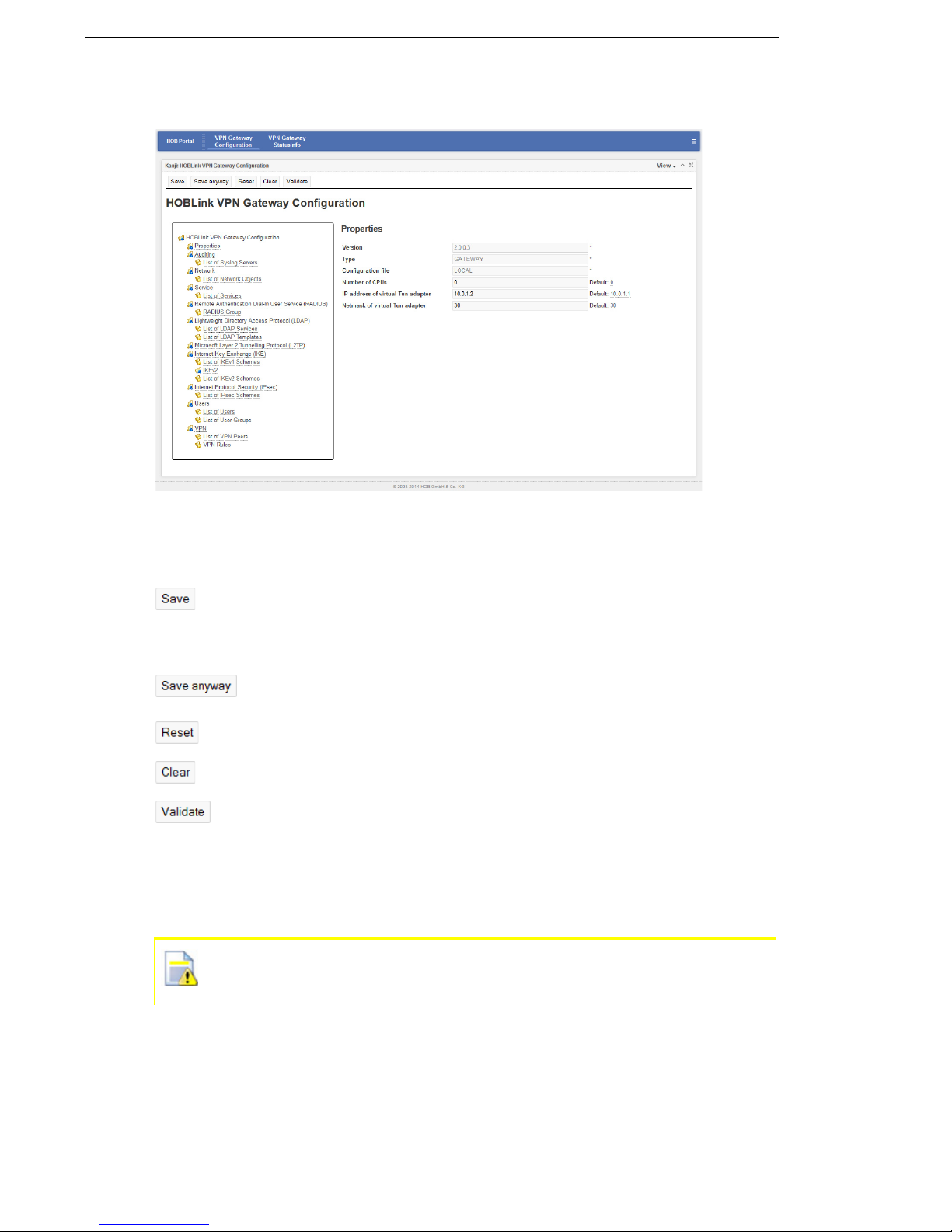
Figure 17: HOBLink VPN Gateway Configuration Properties - Maximized Display
The buttons at the top of the screen are common throughout the configuration
interface and have the following functions.
click Save to save the edited entries. This command includes
automatic validation of the data. Make sure to do this regularly or after
you are finished editing HOBLink VPN Gateway. It is not necessary to
save each screen once edits have been made.
click Save anyway to save even if the data is invalid. This option does
not include automatic data validation.
click Reset to clear any edits and revert to the previously saved data.
click Clear to clear the current information in the entry fields.
click Validate to make sure that any data entered in these fields is valid.
On the left side of the maximized interface, the elements of the HOBLink VPN
configuration are displayed in a hierarchical structure, making it easier to select the
element to be configured. On the right side of the interface, the properties of the
selected element are displayed.
An asterisk denotes all fields where data input is mandatory. If no data is
entered into these fields, you cannot save the configuration correctly as it
is not valid and you will receive an onscreen alert to this effect.
The entry fields for the Properties interface are as follows:
Version – the current version of the HOBLink Configuration software.
Type – how the machine is currently configured.
30 Security Solutions by HOB
Page 31

HOBLink VPN Gateway Configuring HOBLink VPN Gateway
Configuration file – the location of the current configuration file, which must
currently be a locally stored xml file.
Number of CPUs – this setting controls the number of threads started by the
gateway. The more CPUs available the more threads are started, if needed. The
default value of zero lets HOBLink VPN automatically retrieve the real number of
CPUs.
IP address of virtual TUN adapter – the current IP address of the virtual TUN
adapter. A subsequent field shows the default address.
Netmask of virtual TUN adapter – this setting completes the network configuration
of the TUN adapter. The default value of 30 bits sets up the smallest possible
network of only 4 addresses.
Make sure to click Save when you have finished making edits to the data
on this screen. it is also recommended that you use the Validate button to
make sure that all the data entered is valid.
Please note: This is a formal proof only. The configuration data being
reported as being valid at this level does not necessarily mean that it will
be accepted by the HOBLink VPN Gateway.
5.2 Auditing
Logfiles are necessary to record all activity in a system. This allows the
administrator to monitor the performance of the system as well as identify any faults
or errors that may occur.
Figure 18: Auditing
Security Solutions by HOB 31
Page 32

Configuring HOBLink VPN Gateway HOBLink VPN Gateway
Select the Enable syslog checkbox. Syslog servers where the logfiles can be
written can now be set up on the following screen.
The checkbox Enable syslog needs to be checked to generally enable the
logging functionality.
5.2.1 List of Syslog Servers
A list of the syslog servers that are currently configured for your system is displayed.
Figure 19: List of Syslog Servers
The buttons for the syslog server list on this screen have the following functions:
click New to create a new entry in the list of machines that can be used
as syslog servers for writing and storing log files. You will then be
prompted to enter a name as an identifier for the new syslog server.
click Clone to clone the selected syslog server. The clone must be given
a new name and IP address to avoid future conflicts.
click Remove to remove the selected syslog server from the list.
Use the arrow buttons to manage the order in which the servers appear in this list.
You can set the following on this screen:
Name – enter the name of the machine being used as the syslog server, where the
log files will be written and stored. This is a required field.
IP address – enter the IP address of the machine being used as the syslog server,
where the log files will be written and stored. This is a required field.
32 Security Solutions by HOB
Page 33

HOBLink VPN Gateway Configuring HOBLink VPN Gateway
5.3 Network
HOBLink VPN Gateway allows objects to be connected to create a VPN. In the
screen shown here you can configure the individual objects.
The List of Network Objects screen allows the configuration of objects of type
Gateway, Network, Workstation and Group.
Group type objects can contain any other network objects.
Gateway type objects are mainly used in the HOBLink VPN Gateway configuration,
under List of VPN Peers.
Network type objects are used in different parts of the configuration, for example as
the Intranet for a gateway, or as the source or destination of a VPN rule.
Figure 20: List of Network Objects
List of Network Objects
A list of the network objects that are currently configured for your system is
displayed here. The buttons below the list have the following functions:
click New to create a new entry in the list of network objects that can be
added to your system. You will then be prompted to enter a name as an
identifier for the new network object.
click Clone to clone the selected object. The clone must be given a new
name and other configuration data to avoid future conflicts.
click Remove to remove the selected network object from the list.
Use the arrow buttons to manage the order in which the network objects appear in
this list. The entry fields for the Network Object interface are as follows:
Name – enter the name of the object you are adding to your network. This is a
required field.
Description – enter a description for the object to make it easier to identify.
Security Solutions by HOB 33
Page 34

Configuring HOBLink VPN Gateway HOBLink VPN Gateway
Type – select an object type or use the default (Gateway).
IP address – enter the IP address of the object. This is a required field. This field is
only shown if the Type is Gateway or Workstation and the Roaming checkbox
is not enabled.
Intranet name – select the network object that defines the intranet of this gateway.
This field is only shown if the Type is Gateway.
Roaming – enable to allow this object to roam and still maintain a connection to
your network. This field is only shown if the Type is Gateway.
List of group members – this is the list of network objects that belong to the group.
This field is only shown if the Type is Group.
5.4 Service
HOBLink VPN Gateway allows services to be configured for your system. These
services can be used across the network.
Services configured here are used in VPN Rules to specify the data traffic that is
allowed to go through a VPN tunnel.
The List of Services screen shows the list of services that are available for
configuration.
Figure 21: List of Services
34 Security Solutions by HOB
Page 35

HOBLink VPN Gateway Configuring HOBLink VPN Gateway
List of Services
A list of all services that are currently configured in your system is displayed here.
The buttons below the list have the following functions:
click New to create a new service to add to the list. You will then be
prompted to enter a name as an identifier for this new service. After
entering a name and clicking OK, the service is created and appears in
the List of Services.
click Clone to clone the selected service. The new group must be given
a new identifier for the new service.
click Remove to remove the selected service from the list.
Use the arrow buttons to manage the order in which the services appear in this list.
The entry fields for the List of Services interface are as follows:
Name – each service must be given a distinguishable name. This is a required field.
Description – enter a short description of the service.
Type – the service type. Select a type, the default is Generic protocol. This is
a required field.
Protocol number – enter the protocol number assigned to this service. This field is
only shown if the Type is Protocol.
The following fields are only shown if the service type entered under Type
is TCP port or UDP port.
Any source port – select to activate or deactivate the source port field.
Source port – enter a specified source port.
Any destination port – activates or deactivates the destination port field.
Destination port – enter a specific destination port.
5.5 Remote Authentication Dial In User Service (RADIUS)
HOBLink VPN Gateway allows you to configure a single RADIUS server or a group
of RADIUS servers for your system. RADIUS is a network protocol standard used
to manage access, authentication and authorization of users in a network.
This screen allows you to configure RADIUS groups (with one or more RADIUS
server each).
To configure a RADIUS server, it is necessary to create a RADIUS group,
either with only one server or with several servers.
Security Solutions by HOB 35
Page 36

Configuring HOBLink VPN Gateway HOBLink VPN Gateway
Figure 22: List of RADIUS Groups
RADIUS Group
Here a list of the groups is shown. When you select a RADIUS group, the RADIUS
servers configured in this group are shown in a list below.
The buttons below this panel have the following functions:
click New to create a new entry in the list of RADIUS groups. You will
then be prompted to enter a name as an identifier for the new group.
click Clone to clone the selected group. The new group must be given a
new name and other configuration data to avoid future conflicts.
click Remove to remove the selected RADIUS group from the list.
Use the arrow buttons to manage the order in which the RADIUS groups appear in
this list. The entry fields for the RADIUS Group interface are as follows:
Name – enter the name of the RADIUS group you are adding to your network. This
is a required field.
Corresponding LDAP service – select the LDAP service to use for the RADIUS
group.
Option – select an option to change the protocol for RADIUS servers of the group.
The default is None.
Character setting – select the character setting to be used (default is UTF-8).
Timeout(s) – specify a timeout (in seconds) for a RADIUS server to respond. If a
connection is not made within this time, then the connection attempt moves to the
next server in the group. If this next server also does not respond, the attempt is
made with each server in the group until a response is received. The default is 10.
36 Security Solutions by HOB
Page 37

HOBLink VPN Gateway Configuring HOBLink VPN Gateway
Comment – enter a comment to help you identify or manage this group.
RADIUS Server
In this part of the interface you can configure a RADIUS server belonging to the
selected RADIUS group. The buttons below this panel have the following functions:
click New to create a new entry in the list of RADIUS servers. You will
then be prompted to enter a name as an identifier for the new server.
click Clone to clone the selected RADIUS server. The new server must
be given a new name and other configuration data to avoid future
conflicts.
click Remove to remove the selected RADIUS server from the list.
Use the arrow buttons to manage the order in which the RADIUS servers appear in
this list. The entry fields for the RADIUS Server interface are as follows:
Name – enter the name of the RADIUS server you are adding to the selected
RADIUS group. This is a required field.
RADIUS server IP address – enter the IP address of the RADIUS server.
UDP port number – enter the UDP port that will be used for connections to this
server.
Shared secret – enter the Shared Secret to be used for this server. If you are not
sure of the secret being used, click the Show button to display it.
Comment – enter a comment to help you identify or manage this RADIUS server.
5.6 Lightweight Directory Access Protocol (LDAP)
LDAP is a standard application protocol used for managing directory information
services over a network. LDAP provides for the sharing of user, system and network
information throughout the network.
For HOBLink VPN Gateway, many different types of LDAP may be used, with each
LDAP service having its own configuration. These different LDAP services can be
based on different LDAP templates that can also be configured in this section.
Security Solutions by HOB 37
Page 38

Configuring HOBLink VPN Gateway HOBLink VPN Gateway
5.6.1 List of LDAP Services
Using this interface you can enter and manage the LDAP services that you wish to
use for this configuration.
Figure 23: List of LDAP Services
List of LDAP Services
This table holds a list of LDAP services in your network. Until an LDAP service has
been selected here the LDAP Entry section consisting of a LDAP servers list and
the parameters of the selected server in this list is disabled. The buttons below this
list have the following functions:
click New to create a new entry in the list of LDAP services. You will then
be prompted to enter a name as an identifier for this new service.
click Clone to clone an existing service. The clone must be given a new
name to avoid future conflicts.
click Remove to remove the selected service from the list.
Use the arrow buttons to manage the order in which the LDAP services appear in
this list.
Name – enter the name of the LDAP service you are adding to your network. This
is a required field.
38 Security Solutions by HOB
Page 39

HOBLink VPN Gateway Configuring HOBLink VPN Gateway
LDAP Entry
Here you can add LDAP servers to the selected LDAP service and configure them.
The buttons below this list have the following functions:
click New to create a new entry in the list of LDAP servers of the selected
LDAP service. You will then be prompted to enter a name as an identifier
for this new server.
click Clone to clone an existing server. The clone must be given a new
name to avoid future conflicts.
click Remove to remove the selected server from the list.
Use the arrow buttons to manage the order in which the LDAP entries appear in this
list. The entry fields for the LDAP Entry part of this interface are as follows:
Name – enter the name of the LDAP server you are adding to your network. This is
a required field.
Comment – enter a comment to help you in identifying and managing the LDAP
server.
Server IP address – enter the IP address of the LDAP server.
Server port – enter the LDAP port number of the server.
Connection waiting duration – specify a limit (in seconds) for an LDAP server to
respond before the connection attempt moves to the next server in the service. The
default is 5.
Search nested groups (depth level) – enter here the depth to which any searches
are to be performed. The default is 1.
Global directory – enable to allow the use of the global directory of your system by
this LDAP server.
Base DN – enter the Base DN (Distinguished Name) for the LDAP server.
Search timeout(s) – the timeout length for a search of the LDAP to be performed,
in seconds. The default is 5 seconds.
Retry after error(s) – the amount of time in seconds that a connection attempt must
wait to be made again after a failed attempt. The default is 5 seconds.
Search result buffer size – the maximum amount of data that will be returned from
the LDAP server following a successful search. The allowed range of entries is
1024 - 65535, the default is 1024.
Maximum sessions – the maximum number of concurrent connections that can be
made. The default is 1.
DN – the DN to be used for this element of the LDAP.
Password – enter the password to be used for this LDAP element. Click Show to
show the password so that it can be read for confirmation purposes.
LDAP template – select the LDAP template to be used for this server. For more
information on the LDAP template, see the next section.
Security Solutions by HOB 39
Page 40

Configuring HOBLink VPN Gateway HOBLink VPN Gateway
5.6.2 List of LDAP Templates
Using this interface you can enter and manage the LDAP templates that you wish
to use for this configuration.
All fields on this screen must be completed in order configure an LDAP
template.
Figure 24: List of LDAP Templates
List of LDAP Templates
Here you can configure LDAP templates for your system. A list of configured LDAP
templates is displayed. The buttons below the list have the following functions:
click New to create a new entry in the list of LDAP templates. You will
then be prompted to enter a name as an identifier for this new template.
click Clone to clone the selected template. The clone must be given a
new name to avoid future conflicts.
click Remove to remove the selected template from the list.
Use the arrow buttons to manage the order in which the LDAP templates appear in
this list. The entry fields for the List of LDAP Templates interface are as follows:
Name – enter the name of the LDAP template you are adding to your network.
User attribute – enter the user attribute to be used for this template.
Group attribute – enter the group attribute to be used.
Member attribute – enter the member attribute to be used.
User prefix – enter the user prefix to be used.
40 Security Solutions by HOB
Page 41

HOBLink VPN Gateway Configuring HOBLink VPN Gateway
Search default attribute – enter the attribute to be used as the default for any
search performed.
5.7 Microsoft Layer 2 Tunneling Protocol (L2TP)
Microsoft Layer 2 Tunneling Protocol (L2TP) is a tunneling protocol that is used to
support tunneling in many VPNs. HOBLink VPN Gateway also supports L2TP.
Figure 25: L2TP
The entry fields for the Microsoft Layer 2 Tunneling Protocol (L2TP) interface are
as follows:
Virtual local IP address – enter the virtual local IP address of the machine hosting
the L2TP protocol. This is a required field.
Receive window size – the size of the window that will be receiving the
communicated data. The default is 4.
Keepalive interval – the keepalive mechanism is employed by L2TP in order to
check whether the IPsec tunnel is still working. The default is 60 seconds.
IPsec scheme – select the IPsec scheme to be used. The L2TP protocol does not
provide encryption by itself, but HOBLink VPN Gateway provides for IPsec to be
used.
Keepalive logging – enable this to allow logging of any keepalives when L2TP is
used.
Security Solutions by HOB 41
Page 42

Configuring HOBLink VPN Gateway HOBLink VPN Gateway
5.8 Internet Key Exchange (IKE)
IKE is the protocol used in IPsec to set up a security association (SA). IKEv2 is an
expanded and improved version of IKE, HOBLink VPN Gateway facilitates the use
of both versions.
Here you specify the IKE scheme (Version 1) to be used by default, which is
important in Main mode.
Figure 26: IKE - Select IKE Scheme
The entry field for the Internet Key Exchange (IKE) interface is as follows:
Default IKEv1scheme – select a scheme to be used as the default. The selection
for Gateway Authentication for the selected scheme should be Pre-shared
Key, because a scheme with certificates is not supported by the present version.
The default setting is No default IKE scheme.
42 Security Solutions by HOB
Page 43

HOBLink VPN Gateway Configuring HOBLink VPN Gateway
5.8.1 List of IKEv1 Schemes
Using this interface you can enter and manage the IKEv1 schemes that you wish to
use for this configuration.
Figure 27: List of IKEv1 Schemes
List of IKEv1 Schemes
A list of configured IKEv1 schemes is displayed. The buttons below the list have the
following functions:
Security Solutions by HOB 43
click New to create a new entry in the list of IKEv1 schemes. You will then
be prompted to enter a name as an identifier for this new scheme.
click Clone to clone the selected scheme. The clone must be given a new
name to avoid future conflicts.
click Remove to remove the selected scheme from the list.
Page 44

Configuring HOBLink VPN Gateway HOBLink VPN Gateway
Use the arrow buttons to manage the order in which the IKE schemes appear in this
list. The entry fields for the List of IKEv1 Schemes interface are as follows:
Name – enter the name of the scheme you are adding to your network. This is a
required field.
Description – enter a description of the scheme to help identification and
management of the scheme.
Mode – select the mode for the IKE scheme. The supported modes are Main
(default) and Aggressive.
Authentication mode – select the mode for authentication. The supported modes
are None (default), HYBRID and XAUTH.
Initiator Identification Type – select the identification type. The supported types
are IP address (INETA), Fully qualified domain name (FQDN) and Fully
qualified username (USER_FQDN). Default is IP address.
Encryption – select the type of encryption you wish to use from the list of those
available in the list on the left by using the horizontal arrow buttons. You can then
use the vertical arrow buttons to manage the list of encryption types that have
already been selected. Supported types are AES128, AES192, AES256, 3DES,
BLOWFISH448 and CAST128.
Hash – select the type of hash functions you wish to use from the list of those
available in the list on the left by using the horizontal arrow buttons. You can then
use the vertical arrow buttons to manage the list of hash functions types that have
already been selected. Supported functions are SHA1 and MD5.
Note: when a DSA certificate is used as the Gateway Authentication
method, the use of SHA1 is required.
Gateway authentication – select the type of gateway authentication methods you
wish to use from the list of those available in the list on the left by using the
horizontal arrow buttons. You can then use the vertical arrow buttons to manage the
list of gateway authentication methods that have already been selected. Supported
methods are RSA, DSA and Pre-shared key.
Diffie-Hellmann group – select the type of Diffie-Hellmann groups you wish to use
from the list of those available in the list on the left by using the horizontal arrow
buttons. You can then use the vertical arrow buttons to manage the list of
Diffie-Hellmann groups that have already been selected. The supported groups are
MODP768
, MODP1024, MODP1536, MODP2048, MODP3072v MODP4096,
MODP6144, MODP8192, EC2NGF163, EC2NGF283, EC2NGF409 and
EC2NGF571.
IKE SA lifetime (seconds) – enter the desired lifetime for the IKE security
association (SA). The range is between 300-2419200 seconds, the default is
604800 seconds.
UDP timeout – enter the UDP timeout in seconds. The value should be between
1-600, 10 is the default timeout.
UDP retries – enter the number of UDP retries permitted. The value should be
between 0-20, 2 is the default value.
44 Security Solutions by HOB
Page 45

HOBLink VPN Gateway Configuring HOBLink VPN Gateway
Pre-shared key – enter the pre-shared key. You can use the Hide/Show button to
hide or show the value.
Note: This is only mandatory if the methods chosen for Gateway
authentication include Pre-shared key.
Certificate name – the name of the certificate used when the entry for Gateway
authentication includes DSA or RSA. If this field is empty, the first certificate in the
database is used.
Enable authentication retries – enable if the authentication process should be
repeated several times after a failed authentication. This is enabled by default.
Maximum allowed authentication retries – the maximum number of allowed
authentication retries. The value should be in the range of 1-5, the default is 3. This
field is only shown if Enable authentication retries is enabled.
Detect NAT device(s) – enable to allow the detection of NAT device(s). This is
enabled by default.
Enable dead peer detection (DPD) – enable to allow the detection of dead or
unresponsive peers. This is enabled by default.
The following options are only shown if dead peer detection has been
enabled.
Enable DPD logging – enable to allow the logging of DPD. This is disabled by
default.
DPD inbound data timeout – the DPD data timeout in seconds. The value should
be in the range of 1-86400, the default is 60.
DPD timeout – the DPD wait timeout in seconds. The value should be in the range
of 1-600, the default is 10.
DPD retries – the number of DPD retries permitted. The value should be in the
range of 0-20, the default is 2.
Security Solutions by HOB 45
Page 46

Configuring HOBLink VPN Gateway HOBLink VPN Gateway
5.8.2 IKEv2
This screen holds general IKEv2 parameters that are being used in this HOBLink
VPN Gateway configuration. Other parameters that may be individual for each peer
are held in IKEv2 schemes, see Section 5.8.3 List of IKEv2 Schemes on page 47
for more information.
Figure 28: IKEv2
The fields for entry on this page are:
Diffie-Hellmann group – select the Diffie-Hellmann groups you wish to use from
the list of those available in the list on the left by using the horizontal arrow buttons.
You can then use the vertical arrow buttons to manage the list of Diffie-Hellmann
groups that have already been selected. The supported groups are MODP768,
MODP1024, MODP1536, MODP2048, MODP3072, MODP4096, MODP6144,
MODP8192, EC2NGF163, EC2NGF283, EC2NGF409 and EC2NGF571.
Encryption – select the types of encryption you wish to use from the list of those
available in the list on the left by using the horizontal arrow buttons. You can then
use the vertical arrow buttons to manage the list of encryption types that have
already been selected. Supported types are AES128, AES192, AES256 and 3DES.
Pseudo random function – select the pseudo random functions you wish to use
from the list of those available in the list on the left by using the horizontal arrow
buttons. You can then use the vertical arrow buttons to manage the list of pseudo
random functions that have already been selected. Supported types are
HMAC_SHA1 and HMAC_MD5.
46 Security Solutions by HOB
Page 47
HOBLink VPN Gateway Configuring HOBLink VPN Gateway
Hash – select the hash functions you wish to use from the list of those available in
the list on the left by using the horizontal arrow buttons. You can then use the
vertical arrow buttons to manage the list of hash functions that have already been
selected. Supported types are HMAC_SHA1 and HMAC_MD5.
Note: when a DSA certificate is used as the Gateway Authentication
method, the use of HMAC_SHA1 is required.
Gateway authentication – select the gateway authentication methods you wish to
use from the list of those available in the list on the left by using the horizontal arrow
buttons. You can then use the vertical arrow buttons to manage the list of gateway
authentication methods that have already been selected. Supported methods are
RSA, DSA and Pre-shared key.
Pre-shared key – enter the pre-shared key. Click Hide/Show to blend out the value
out or to display it if already blended out.
Note: This is mandatory only if the methods chosen for Gateway
authentication include Pre-shared key.
Certificate name – the name of the certificate used when the entry for Gateway
authentication includes DSA or RSA signatures. If this field is empty, the first
certificate in the database is used.
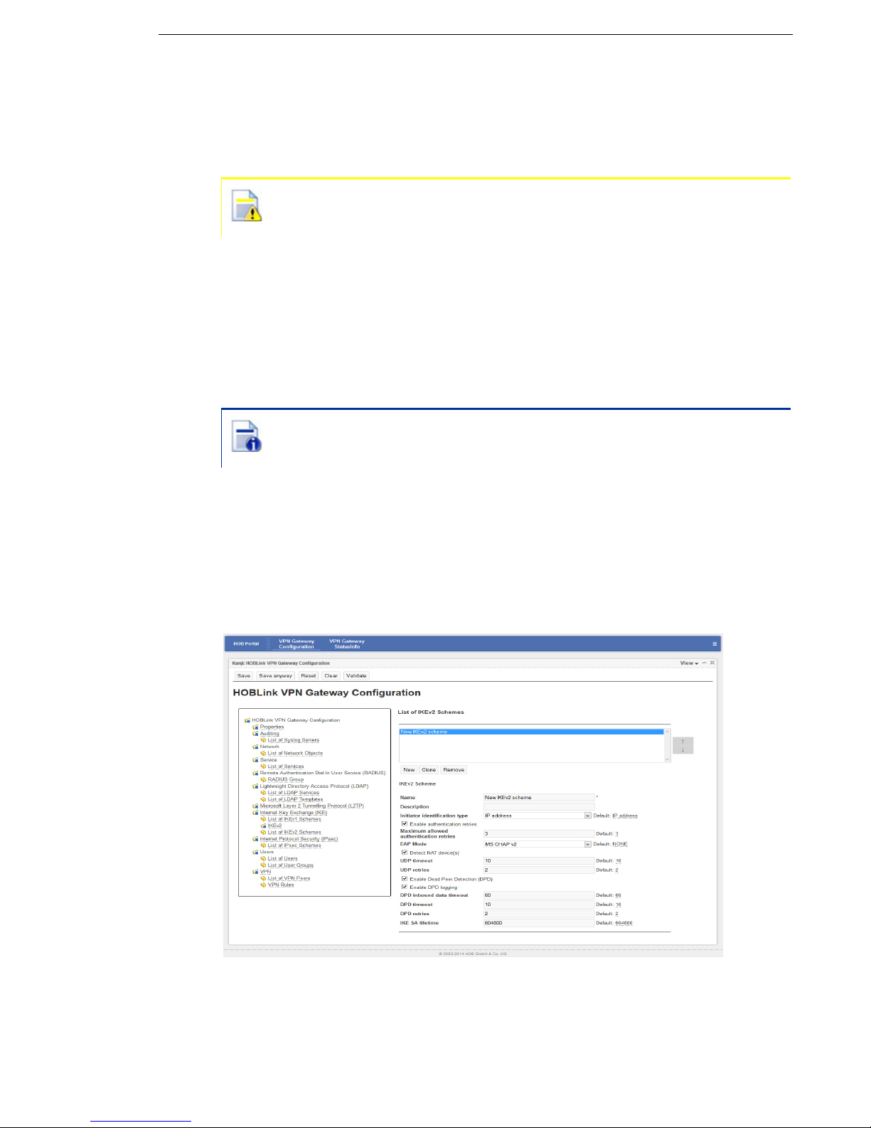
5.8.3 List of IKEv2 Schemes
Using this interface you can enter and manage the IKEv2 schemes that you wish to
use for this configuration.
Figure 29: List of IKEv2 Schemes
Security Solutions by HOB 47
Page 48

Configuring HOBLink VPN Gateway HOBLink VPN Gateway
List of IKEv2 Schemes
A list of configured IKEv2 schemes is displayed here. The buttons below the list
have the following functions:
click New to create a new entry in the list of IKEv2 schemes. You will then
be prompted to enter a name as an identifier for the new scheme.
click Clone to clone the selected scheme. The clone must be given a new
name to avoid future conflicts.
click Remove to remove the selected scheme from the list.
Use the arrow buttons to manage the order in which the IKEv2 schemes appear in
this list. The entry fields for the List of IKEv2 Schemes interface are as follows:
Name – enter the name of the scheme you are adding to your network. This is a
required field.
Description – enter a description of the scheme to help identification and
management of the scheme.
Initiator identification type – select the identification type from the dropdown box.
The supported types are IP address (INETA) and Name of that gateway
(Fully Qualified Distinguished Name - FQDN), which can be configured in Section
5.11 VPN on page 54. Default is IP address.
Enable authentication retries – enable to allow the authentication process to be
repeated several times after a failed authentication. This is enabled by default.
Maximum allowed authentication retries – the maximum number of allowed
authentication retries. The value should be in the range of 1-5, the default is 3. This
field is only shown if Enable authentication retries is enabled.
EAP mode – EAP (Extensible Authentication Protocol) mode is used when a client
requests EAP authentication. The supported modes are None (this is the default
mode), GTC, MD5 and MSCHAPv2.
Detect NAT device(s) – enable to allow the detection of NAT device(s). This is
enabled by default.
UDP timeout – enter the UDP timeout in seconds. The value should be between
1-600, 10 is the default.
UDP retries – enter the number of UDP retries permitted. The value should be
between 0-20, 2 is the default.
Enable dead Peer detection (DPD) – enable to allow the detection of dead or
unresponsive peers. This is enabled by default.
The next 4 options are shown only if Dead Peer Detection has been
enabled.
Enable DPD logging – enable to allow the logging of DPD. This is disabled by
default.
DPD inbound data timeout – the DPD data timeout in seconds. The value should
be in the range of 1-86400, the default is 60.
48 Security Solutions by HOB
Page 49

HOBLink VPN Gateway Configuring HOBLink VPN Gateway
DPD timeout – the DPD wait timeout in seconds. The value should be in the range
of 1-600, the default is 10.
DPD retries – the number of DPD retries permitted. The value should be in the
range of 0-20, the default is 2.
IKE SA lifetime (seconds) – enter the desired lifetime for the IKE security
association (SA). The range is between 300-1209600 seconds, the default is
604800.
5.9 Internet Protocol Security (IPsec)
HOBLink VPN Gateway uses the IPsec security protocol to encrypt the
communications between the peers in the network. How this is done can be
configured in the following sections. This following screen shows the IPsec scheme
that is defined by default for all new connections.
Figure 30: IPsec
The entry field for the Internet Protocol Security (IPsec) interface is as follows:
Default IPsec scheme – select from the drop down box the IPsec scheme to be
defined as the default scheme for all new connections. The default is No default
IPsec scheme.
Security Solutions by HOB 49
Page 50

Configuring HOBLink VPN Gateway HOBLink VPN Gateway
5.9.1 List of IPsec Schemes
Using this interface you can enter and manage the list of IPsec schemes that you
wish to use for this configuration.
Figure 31: List of IPsec Schemes
List of IPsec Schemes
Here you can individually configure the IPsec schemes that can be used in
HOBLink VPN Gateway. The buttons below this list have the following functions:
click New to create a new entry in the list of IPsec schemes. You will then
be prompted to enter a name as an identifier for this new scheme.
click Clone to clone the selected scheme. The clone must then be given
a new name to avoid future conflicts.
click Remove to remove the selected scheme from the list.
Use the arrow buttons to manage the order in which the IPsec schemes appear in
this list. The entry fields for each IPsec scheme are as follows:
Name – enter the name of the scheme you are adding to your network. This is a
required field.
50 Security Solutions by HOB
Page 51

HOBLink VPN Gateway Configuring HOBLink VPN Gateway
Description – enter a description of the scheme to help identification and
management of the scheme.
Protocol – select the type of IPsec protocol to be used. The supported protocols
are NONE, ESP, AH and AHESP. The default option NONE can only be specified if
Compression is not NONE. The option AHESP is not supported for IKEv2.
Mode – select the operation mode to be used. The supported modes are TUNNEL
(default) and TRANSPORT, which is only valid if the Protocol is ESP.
AH integrity – select the integrity methods you wish to use from the list of those
available in the list on the left by using the horizontal arrow buttons. You can then
use the vertical arrow buttons to manage the list of integrity methods that have
already been selected. The supported methods are HMAC_SHA1 and HMAC_MD5.
This field is only shown when the selected Protocol is AH or AHESP.
ESP encryption – select the encryption types you wish to use from the list of those
available in the list on the left by using the horizontal arrow buttons. You can then
use the vertical arrow buttons to manage the list of encryption types that have
already been selected. The supported types are AES128, AES192, AES256, 3DES,
ARCFOUR, BLOWFISH128, CAST128 and NULL. The methods ARCFOUR,
BLOWFISH128 and CAST128 are not supported in IKEv2. This field is only shown
when the Protocol is ESP or AHESP.
ESP integrity – select the integrity methods you wish to use from the list of those
available in the list on the left by using the horizontal arrow buttons. You can then
use the vertical arrow buttons to manage the list of integrity methods that have
already been selected. The supported methods are HMAC_SHA1
and HMAC_MD5.
This field is only shown when the selected Protocol is ESP or AHESP.
Compression – the compression protocol that is used. The supported protocols
are None (default) and IPCOMP. The option None can only be specified if Protocol
is not None.
Enable perfect forward secrecy (PFS) – check this box to enable perfect forward
secrecy. This is disabled by default.
Diffie-Hellmann group – select the Diffie-Hellmann group to be used with PFS.
The supported groups are the same as those that are supported in IKE. This field is
only shown if PFS is enabled.
IPsec SA lifetime (seconds) – the SA lifetime in seconds. The value should be in
the range of 120–604800, 28800 is the default.
Enable IPsec SA lifetime (kilobytes) - check to specify the IPsec SA lifetime in
kilobytes. This is disabled by default.
IPsec SA lifetime (kilobytes) – specify the maximum SA volume in kilobytes. This
is disabled by default and is shown only when the previous check box is enabled.
The value should be in the range 1024 - 1048576, 102400 is the default value.
Replay detection – enable to allow replay detection. This is disabled by default.
Use UDP encapsulation – select how UDP encapsulation should be used, the
supported options are Never (default), Always and On NAT detected.
NAT keepalive (seconds) – enter the duration (in seconds) between two
successive NAT keepalive retransmissions. The value should be in the range of
0-86400 (0 deactivates NAT keepalive retransmissions and is also the default).
Security Solutions by HOB 51
Page 52

Configuring HOBLink VPN Gateway HOBLink VPN Gateway
This field is only shown when the UDP encapsulation value used is either Always
or On NAT detected.
5.10 Users
In this section, users and user groups can be configured.
5.10.1 List of Users
Using this interface you can enter and manage the list of users that you wish to use
for this configuration.
Figure 32: List of Users
List of Users
The users of HOBLink VPN Gateway also need to be configured. A list of configured
users is displayed here.
The buttons below this list have the following functions:
click New to create a new entry in the list of users. You will then be
prompted to enter a name as an identifier for this new user.
click Clone to clone the selected user. The clone must be given a new
name to avoid future conflicts.
click Remove to remove the selected user from the list.
Use the arrow buttons to manage the order in which the users appear in this list.
The entry fields for the User interface are as follows:
Name – enter the name of the user you are adding to your network. This is a
required field.
Description – enter a description of the user to help identification and management
of the user.
52 Security Solutions by HOB
Page 53

HOBLink VPN Gateway Configuring HOBLink VPN Gateway
Password – the password used for the direct authentication of this user.
Member of group(s) – select the user groups you wish this user to be a member
of from the list of those available in the list on the left by using the horizontal arrow
buttons. You can then use the vertical arrow buttons to manage the list of user
groups that have already been selected.
5.10.2 List of User Groups
Using this interface you can enter and manage the list of user groups that you wish
to use for this configuration.
Figure 33: List of User Groups
List of User Groups
The user groups of HOBLink VPN Gateway also need to be configured. A list of
configured user groups is displayed here. The buttons below this list have the
following functions:
click New to create a new entry in the list of user groups. You will then be
prompted to enter a name as an identifier for this new user group.
click Clone to clone the selected user group. The clone must be given a
new name to avoid future conflicts.
click Remove to remove the selected user group from the list.
Use the arrow buttons to manage the order in which the user groups appear in this
list. The entry fields for the User Group interface are as follows:
Name – enter the name of the user group you are adding to your network. This is a
required field.
Description – enter a description of the group to help identification and
management of the user group.
Security Solutions by HOB 53
Page 54

Configuring HOBLink VPN Gateway HOBLink VPN Gateway
5.11 VPN
HOBLink VPN Gateway enables a VPN to be established between multiple devices.
It needs to be installed on a host device, and the other participants, also known as
VPN Peers, in the communication network are then facilitated in their
communications by this host. The VPN host, peers and rules can be configured in
this section.
Figure 34: VPN
The entry fields for the VPN interface are as follows:
Name – enter the name of the gateway that hosts the VPN. This field is required
when the Initiator identification type set in the IKEv1/IKEv2 configuration is FQDN
or USER_FQDN (see Section 5.8 Internet Key Exchange (IKE) on page 42).
IKE port – the UDP port number used for the IKE protocol. The value should be in
the range of 1–65535. The default is 500.
UDP encapsulation (NAT-T) Port – the UDP port number used for UDP
encapsulation. The value should be in the range of 1-65535. The default is 4500.
RPC port (Remote Procedure Call) – the port number used for remote procedure
calls. The value should be in the range of 1-65535. The default is 13131.
Default action – the default action for the VPN rules. The permitted actions that you
can select are PASS, DROP (default) and REJECT.
ESP substitute protocol number – (only used by Windows systems) the value
should be in the range of 1-255. The default is 142.
AH substitute protocol number – (only used by Windows systems) the value
should be in the range of 1-255. The default is 143.
IPCOMP substitute – (only used by Windows systems) the value should be in the
range of 1-255. The default is 144.
54 Security Solutions by HOB
Page 55

HOBLink VPN Gateway Configuring HOBLink VPN Gateway
IPIP substitute – (only used by Windows systems) the value should be in the range
of 1-255. The default is 145.
NATT substitute – (only used by Windows systems) the value should be in the
range of 1-255. The default is 146.
5.11.1 List of VPN Peers
Using this interface you can enter and manage the list of VPN peers that you wish
to use for this configuration. You can define the features of the channel to establish
the connection.
Figure 35: List of VPN Peers
List of VPN Peers
Here you configure the peers you want to use with the VPN. You can also define
the features of the channel to establish the connection. The buttons below this list
have the following functions:
click New to create a new entry in the list of VPN peers. You will then be
prompted to enter a name as an identifier for this new peer.
click Clone to clone the selected peer. The clone must be given a new
name to avoid future conflicts.
click Remove to remove the selected peer from the list.
Use the arrow buttons to manage the order in which the VPN peers appear in this
list. The entry fields for the List of VPN Peers interface are as follows:
Name – select from the dropdown box the name of the VPN peer to be added to
your VPN network. The name has been created previously as the name of a
network object, user or user group. As VPN peer only the types User, User Group
and Gateway are allowed as the network object type. This is a required field.
Security Solutions by HOB 55
Page 56

Configuring HOBLink VPN Gateway HOBLink VPN Gateway
Enabled – check to enable the peer. This is enabled by default.
Description – enter a description of the peer to help identify and manage it.
Type – select the type category of the peer. Supported types are Gateway
(default), User or User Group. The type selected here should match with the type
of the element selected under Name.
IKE version – enter the IKE version used. The supported versions are 1 (default)
and 2.
IKEv1 scheme – select the name of the IKEv1 scheme for this peer (see Section
5.8 Internet Key Exchange (IKE) on page 42). This field is only shown if the IKE
version selected is 1.
IKEv2 scheme – select the name of the IKEv2 scheme for this peer (see Section
5.8 Internet Key Exchange (IKE) on page 42). This field is only shown if the IKE
version selected is 2.
IKE port – enter the number of the UDP port used for incoming IKE packets. The
value should be in the range of 1–65535. The default is 500.
UDP encapsulation (NAT-T) port – the number of the UDP port used for UDP
encapsulation. The value should be in the range 1–65535. The default is 4500.
Client authentication – the client authentication method used. The supported
methods are local password (default), RADIUS and LDAP. This field is only
shown when the Type is User or Group.
RADIUS group – select the RADIUS group (as previously defined in Section 5.5
Remote Authentication Dial In User Service (RADIUS) on page 35) to use for this
VPN peer. This field is only shown when the Type is User or Group and the Client
authentication selected is RADIUS.
LDAP service – select the LDAP service (as previously defined in Section 5.6
Lightweight Directory Access Protocol (LDAP) on page
37) to use for this VPN peer.
This field is only shown when the Type is User or Group and the Client
authentication selected is LDAP.
Check group membership – enable this to check the group membership of a user
during authentication. This is enabled by default. This field is only shown when the
Type is Group.
If this checkbox is not enabled, there is no group membership check. This
means that any user that exists in the database can connect using any
group (even without membership).
This checkbox must also be enabled to allow different groups to have
different permissions.
Use of virtual IP address – this allows the use of a virtual IP address. The
supported options are Not used (default), IKE negotiation and L2TP/PPP
adapter. This field is only shown when the Type is User or Group.
Virtual IP address and mask – the virtual IP address and mask of this peer (for
example 10.1.1.2/24). This field is only shown when the Type is User and the
Use of virtual IP address is IKE negotiation.
56 Security Solutions by HOB
Page 57

HOBLink VPN Gateway Configuring HOBLink VPN Gateway
Virtual IP pool – select from the drop down box the name of the network object that
contains the pool. This is the pool of virtual IP address and masks of the peer type
User Group. This field is only shown when the Type is Group and the Use of
virtual IP address is IKE negotiation.
The next four options are only shown when the Type is User o r Group and
the Virtual IP address is used.
Primary DNS – the IP address of the primary DNS server.
Secondary DNS – the IP address of the secondary DNS server.
Primary WINS – the IP address of the primary WINS server.
Secondary WINS – the IP address of the secondary WINS server.
PPP/L2TP IP address for a user – here you set the IP address and subnet mask
of the user (for example 172.20.22.222/24). This field is only shown when the
Type is User or Group and the Virtual IP address is L2TP/PPP adapter.
PPP/L2TP IP address pool for a user group – the IP address pool of the user
group. Select from the dropdown box the name of the network object that contains
the pool. This field is only shown when the Type is User or Group and the Virtual
IP address is L2TP/PPP adapter.
5.11.2 VPN Rules
Using this interface you can enter and manage the list of VPN rules that you wish
to use for this configuration. You can also define the features of the tunnel in order
to have proper communication through the VPN.
Figure 36: List of VPN Rules
Security Solutions by HOB 57
Page 58

Configuring HOBLink VPN Gateway HOBLink VPN Gateway
List of VPN Rules
Here you configure the rules to be used with the VPN. The buttons below this list of
configured VPN rules have the following functions:
click New to create a new entry in the list of VPN rules. You will then be
prompted to enter a name as an identifier for this new rule.
click Clone to clone the selected rule. The clone must be given a new
name to avoid future conflicts.
click Remove to remove the selected rule from the list.
Use the arrow buttons to manage the order in which the VPN rules appear in this
list. The entry fields for the VPN Rules interface are as follows:
Name – enter the name of the VPN rule to be added to your network. This is a
required field.
Enabled – check this box to enable the rule. This is enabled by default
Description – enter a description of the rule to help identification and management
of the peer and management of the VPN connection.
Source – select the source of an IP packet or peer name. You can select the name
of a network object of type SUBNET, WORKSTATION or GROUP (but not GATEWAY as
it is not a valid source), or a user name or a user group name as the source. The
initial text shown here of Select source is used in this field only to indicate that
it is necessary to select a valid source to configure a valid rule.
Destination – the destination for an IP packet or peer name. You can select a user
name or a user group name, or the name of a network object (of type SUBNET,
WORKSTATION or GROUP only). A network object of type GATEWAY has a public IP
address and so cannot be used as a valid destination. The initial text shown here of
Select destination is used in this field only to indicate that it is necessary to
select a valid destination to configure a valid rule.
Service – select the name of an IP service or group of services determining the
functionality of the previously specified tunnel (see Section 5.4 Service on page 34).
The default is Any.
Bidirectional – enable to allow this rule to be valid for both directions. This is
disabled by default.
Action – select the way to process the packets. The supported options are IPsec
(default) and IPsec/L2TP. If Source or Destination contain either a user or user
group, then select IPsec/L2TP when the Use of virtual IP address of the
corresponding user or user group peer is set to L2TP/PPP Adapter.
IPsec Scheme
– select from the dropdown box the name of the IPsec scheme to
use in this rule. This field is only shown when Action is IPsec.
Logging – select the type of events you want to register in the log. The supported
options are None (default), All or Errors.
Queueing Priority (1...5) – here you set the priority of packets (specified in the rule
parameters) in the tunnel. It can be beneficial to define the priority to assure a level
of QoS (Quality of Service) for some services if there are several types of packets
58 Security Solutions by HOB
Page 59

HOBLink VPN Gateway Configuring HOBLink VPN Gateway
in a network. Select from 5 queues of priority from 1 (highest) to 5 (lowest), the
default priority is 1.
5.12 VPN Gateway StatusInfo
As a VPN functions across a number of devices simultaneously, it is always
important to be able to check the status of the VPN on the various devices to make
sure that they are functioning properly. HOBLink VPN Gateway provides the status
information for this reason.
5.12.1 System Information
The status information for the complete system is displayed here.
Figure 37: System Information
The system information fields to be seen are as follows:
CPU
Name – the name of the CPU being used.
Manufacturer – the manufacturer of the CPU being used.
Operating System
Name – the name of the current operating system.
Version – the version number and release date of the current operating system.
Release – the release version of the current operating system.
Memory
Total – the total memory of the system.
Available – the current amount of memory that is available.
Network Interfaces – here the various interfaces for the VPN system are shown
with the IP address, subnet mask and MAC address of each interface. In the case
of Tun0, these values mean that the MAC address is not real as the interface is
virtual.
Click Refresh at the bottom of the screen to manually refresh or enable the
Automatically refresh checkbox to refresh at a set time interval.
Security Solutions by HOB 59
Page 60

Configuring HOBLink VPN Gateway HOBLink VPN Gateway
5.12.2 VPN Status
This allows you to check the connections of the machines where the
HOBLink VPN Gateway is running.
Figure 38: VPN Status
The information shown on this screen is divided into two parts:
The panel on the left contains the peers connected to the gateway (with the
channel and tunnels of each connection).
The panel on the right contains the information about the entry selected in the
panel on the left.
If you completely extend the tree of a connection on the left, you can see its channel,
the tunnels established with this gateway and the inbound/outbound traffic with its
SAs.
When you select a peer on the left, some of its parameters are shown on the right.
You can see the type of the peer, the group the peer belongs to in this connection,
and its IP and assigned virtual IP.
When you select the channel of a peer on the left, parameters of the negotiation of
the connection, like IKE version, mode, encryption method, hash method,
authentication method and when the connection was created (and its duration) are
displayed on the right.
When you select a tunnel of a peer on the left, you can see the parameters about
the connection on the right, such as source and destination, configured service,
priority, type, mode, compression used and when the tunnel was created (and
duration).
It is possible to show the inbound/outbound traffic on the right by selecting Inbound/
Outbound SA Bundle of a tunnel on the left. You can also get information about
SA (both inbound and outbound) on the right by selecting the corresponding SA on
the left.
Click Refresh at the bottom of the screen to manually refresh the information on this
screen, or enable the Automatically refresh checkbox to refresh at a set time
interval.
60 Security Solutions by HOB
Page 61

HOBLink VPN Gateway Configuring XML Parameters for HOBLink VPN Gateway
6 Configuring XML Parameters for
HOBLink VPN Gateway
The following is a list of the parameters contained in the vpnconfig.xml file and
an accompanying explanation of each. These parameters may be edited as desired
to improve functionality and applicability within your system or company.
6.1 Configuration Parameters for Properties (properties)
This is a list of the parameters that can be used to configure the properties of
HOBLink VPN Gateway.
Parameters XML Name Description
Version version The default value 2.0.0.3 should
not be changed
Type type Currently 'GATEWAY' is the only
supported value
Configuration file configfile Currently only 'LOCAL' is
supported
Number of CPUs cpus The default value is ‘0’, automatic
detection. Otherwise you need to
enter the actual number of CPUs
of the machine
IP Address of Virtual
Tun Adapter
Netmask of Virtual
TUN Adapter
tun-ineta The default address is 10.0.1.1.
This may be changed if there is an
address conflict in the system,
otherwise this should not be
changed
tun-netmask The range of allowed values is: 1 -
30, the default value is 30
6.2 Configuration Parameters for Auditing (auditing)
It is necessary to activate the Syslog for auditing.
Parameters XML Name Description
Enable Syslog syslog-enabled This enables the writing of log
events to a configurable number of
syslog servers on UDP port 514.
Allowed values: YES or NO
The list of Syslog servers (syslog-server-list) contains the syslog servers
that will be used. Every list entry is grouped in the node syslog-server-entry.
This list contains the parameters that can be entered for Syslog server:
Security Solutions by HOB 61
Page 62

Configuring XML Parameters for HOBLink VPN Gateway HOBLink VPN Gateway
Parameters XML Name Description
Name name This is the unique name for a
Syslog Server
IP Address ineta This is the IP address or DNS
name of your Syslog Server(s)
6.3 Configuration Parameters for Network (network)
The list of network objects (networkobject-list) contains different types of
objects that are used in other parts of the configuration, for example in rules. For
XML every list element is grouped in the node networkobject-entry.
Parameters XML Name Description
Name name Every network object needs to
have a unique name
Description description This may be edited as desired
Type type The types supported are
GATEWAY (this is the default
value), SUBNET,
WORKSTATION, GROUP
Network network This is the only valid for type
SUBNET. This is the IP address
and subnet mask, syntax -
172.22.0.0/16
IP Address ineta This is only valid for types
GATEWAY (with Roaming = NO)
and WORKSTATION. This is the
IP address or DNS name
Intranet Name intranet-name This is only valid for type
GATEWAY. This is the network
object name of the subnet or group
that is the intranet of this gateway
Roaming roaming This is only valid for type
GATEWAY. Check if the gateway
has no fixed external (public) IP
address (YES/NO). The default
value is NO
62 Security Solutions by HOB
Page 63

HOBLink VPN Gateway Configuring XML Parameters for HOBLink VPN Gateway
List of group members member-list This is only valid for type GROUP.
This is a prioritized commaseparated list of network objects
that belong to the group. At least
one network object is required
(network\networkobjectlist\networkobject-entry\name).
The network object names are
used in this list
6.4 Configuration Parameters for Service (service)
The list of services (service-list) used in other parts of the configuration, for
example in VPN rules. For XML every list entry is grouped in the node service-
entry.
Parameters XML Name Description
Name name This is the unique name of the
service
Description description This may be edited as desired
Type type The following types are supported:
Generic protocol (PROTOCOL) any IP protocol number, specified
in the parameter Protocol
Number (protocol-number).
TCP Port (TCP_PORT) - any TCP
session.
UDP Port (UDP_PORT) - any UDP
session.
Group (GROUP) - a group of other
services that have already been
defined
List of group members member-list This is a prioritized
comma-separated list of service
names that are valid only for type
GROUP. The service names
created previously are used in this
list (service\service-list\serviceentry\name)
Allow ANY Source
Port
Security Solutions by HOB 63
any-src-port This is only valid for types TCP
Port and UDP Port. Check if a
source port has been specified
(YES/NO), default is YES
Page 64

Configuring XML Parameters for HOBLink VPN Gateway HOBLink VPN Gateway
Source Port src-port This is only valid for types TCP
Port and UDP Port. It is a specified
source port and is valid if 'any-srcport' = NO. The value should be in
the range 1-65535
Allow ANY Destination
Port
any-port This is only valid for types TCP
Port and UDP Port. Check if a
destination port has been specified
(YES/NO), default is 'NO'
Destination Port
Number
port
This is only valid for types TCP
Port and UDP Port. It is a specified
destination port number and is
valid if 'any-port' = NO. The value
should be in the range 1-65535
Protocol Number
protocol-number
This is only valid for type
PROTOCOL, enter a decimal IP
protocol number
6.5 Configuration Parameters for RADIUS (radius)
It is possible that several groups of RADIUS servers exist, with different
configurations. For XML, every group of RADIUS servers is grouped in the node
radius-group.
The RADIUS group contains a group of RADIUS servers used to authenticate peer
VPN users.
Parameters XML Name Description
Group Name name This is the unique name of the
group of RADIUS servers
Corresponding LDAP
service
correspondingLDAP-service
This is the LDAP group used to
obtain user configuration from a
LDAP server (for example, it takes
the Virtual IP for a user). The
LDAP group name is defined in the
LDAP configuration (ldap\LDAPservice\name). This functionality is
not implemented yet, but it is
possible to select it in the
configuration
64 Security Solutions by HOB
Page 65

HOBLink VPN Gateway Configuring XML Parameters for HOBLink VPN Gateway
Option option Two options are possible:
MS-CHAP-V2 – this protocol is
used to have more secure
communications.
NONE – this is selected when
'option' is empty. It is used the
standard protocol for RADIUS
servers
Characters set charset There are many types of
characters which are available to
be selected. The value by default
is UTF-8
Timeout timeout This is the timeout, in seconds, for
response from RADIUS server
before to use the next server in the
group
Comment comment This may be edited as desired
For XML every RADIUS server list is grouped in the node radius-server.
Parameters XML Name Description
Name name This is the unique name of the
RADIUS server
IP address radius-ineta This is the IP address of the
RADIUS server
Port Number UDP-port This is the RADIUS port number of
that server. The value should be in
the range 1-65535
Shared Secret shared-secret-
plain
Shared Secret
encrypted
shared-secretencrypted
This is the shared secret, in plain
text, of the RADIUS server
This is the shared secret,
encrypted, of the RADIUS server.
Base 64 decoding with the
character set specified in the
group’s 'charset' entry is used.
This and 'shared-secret-plain' are
mutually exclusive, the entry that
appears first is used if both are
configured
Comment comment This may be edited as desired
Security Solutions by HOB 65
Page 66

Configuring XML Parameters for HOBLink VPN Gateway HOBLink VPN Gateway
6.6 Configuration Parameters for IKE (ike)
It is possible to use IKEv1 or IKEv2. The schemes should be selected by default to
be IKEv1.
Parameters XML Name Description
Standard IKEv1
Scheme
6.6.1 List of IKEv1 schemes
The List of IKEv1 schemes (ike-scheme-list) contains a list of IKEv1 schemes
used in the VPN Peers (vpn\peer-list\peer-entry\ike-scheme-name)
configuration. For XML every list element is grouped in the node ike-scheme-
entry.
Parameters XML Name Description
Name name This is the unique name of the
default-ikescheme
This is the scheme used by default
for the IKEv1 connections
IKEv1 scheme
Description description This may be edited as desired
IKE Mode mode Two options are possible, the
supported modes are MAIN and
AGGRESSIVE
Special Authentication
Mode
Initiator Identification
Type
Encryption encryption This is a prioritized comma-
Hash hash This is a prioritized comma-
authenticationmode
initiator-idtype
The supported modes are NONE,
HYBRID and XAUTH
The supported types are 'IP
Address' (INETA), 'Fully Qualified
Distinguished Name' (FQDN),
'Fully Qualified Username'
(USER_FQDN)
separated list of encryption
methods. The supported methods
are AES128, AES192, AES256,
3DES, BLOWFISH448, CAST128
separated list of hash methods.
The supported methods are MD5,
SHA1. If ‘authentication’ is DSA,
the use of SHA1 is required
Gateway
Authentication
66 Security Solutions by HOB
authentication This is a prioritized comma-
separated list of authentication
methods. The supported methods
are 'RSA signatures' (RSA), 'DSA
signatures' (DSA), 'Pre-shared
Key' (PRESHAREDKEY)
Page 67

HOBLink VPN Gateway Configuring XML Parameters for HOBLink VPN Gateway
Diffie-Hellman Group diffie-hellman-
group
This is a prioritized commaseparated list of Diffie-Hellman
groups. The supported groups are
MODP768, MODP1024,
MODP1536, MODP2048,
MODP3072, MODP4096,
MODP6144, MODP8192,
EC2NGF163, EC2NGF283,
EC2NGF409, EC2NGF571
IKE SA Lifetime sa-lifetime The SA lifetime in seconds. The
value should be in the range 3001209600, and 604800 is the value
by default
UDP Timeout UDP-timeout The UDP timeout in seconds. The
value should be in the range 1600, and 10 is the value by default
UDP-retries UDP-retries The number of retries permitted.
The value should be in the range
0-20, and 2 is the value by default
Pre-shared Key preshared-key This is the pre-shared key string. It
is mandatory only if 'authentication'
includes PRESHAREDKEY and
'preshared-key-encrypted' is not
specified
Pre-shared Key
encrypted
preshared-keyencrypted
This is the pre-shared key string
encrypted. This value, encoded
with Base 64, takes precedence
over 'preshared-key'
Name of certificate certificate-name This is the name of certificate used
when the list of 'authentication'
includes DSA or RSA. If this field is
empty, the first certificate in the
database is used
Enable authentication
retries
enable-authretry
Check if it should be repeat the
authentication process several
times after a failed authentication
(YES/NO). The value by default is
'YES'
Maximum allowed
authentication retries
max-auth-retrycount
This is only valid if 'enable-authretry' is enabled. This is the
maximum number of allowed
authentication retries. The value
should be in the range 1-5, and 3 is
the value by default
Detect NAT Device(s) detect-nat This is used to enable the
detection of NAT device(s) (YES/
NO). The value by default is 'YES'
Security Solutions by HOB 67
Page 68

Configuring XML Parameters for HOBLink VPN Gateway HOBLink VPN Gateway
Enable Dead Peer
Detection
DPD This is used to enable the Dead
Peer Detection (YES/NO). The
value by default is 'YES'
Enable DPD logging DPD-logging This is only valid if 'DPD' is
enabled. This is used to enable the
logging of DPD (YES/NO). The
value by default is 'NO'
Inbound data timeout
(s) for DPD
DPD-timer This is only valid if 'DPD' is
enabled. This is the DPD data
timeout in seconds. The value
should be in the range 1-86400,
and 60 is the value by default
DPD timeout DPD-timeout This is only valid if 'DPD' is
enabled. This is the DPD wait
timeout in seconds. The value
should be in the range 1-600, and
10 is the value by default
DPD retries DPD-retries This is only valid if 'DPD' is
enabled. This is the number of
DPD retries permitted. The value
should be in the range 0-20, and 2
is the value by default
6.6.2 List of Common IKEv2 features
The common features of IKEv2 (ike2) contains a list or parameters used for all
IKEv2 connections.
Parameters XML Name Description
Diffie-Hellman Group diffie-hellman-
group
This is a prioritized commaseparated list of Diffie-Hellman
groups. The supported groups are
MODP768, MODP1024,
MODP1536, MODP2048,
MODP3072, MODP4096,
MODP6144, MODP8192,
EC2NGF163, EC2NGF283,
EC2NGF409, EC2NGF571
Encryption encryption This is a prioritized comma-
separated list of encryption
methods. The supported methods
are AES128, AES192, AES256,
3DES
Pseudo-random
function
prf This is a prioritized comma-
separated list of options. The
supported options are
HMAC_MD5, HMAC_SHA1
68 Security Solutions by HOB
Page 69

HOBLink VPN Gateway Configuring XML Parameters for HOBLink VPN Gateway
Hash hash This is a prioritized comma-
separated list of hash methods.
The supported methods are
HMAC_MD5 and HMAC_SHA1. If
‘authentication’ is DSA, the use of
HMAC_SHA1 is required
Gateway
Authentication
authentication This is a prioritized comma-
separated list of authentication
methods. The supported methods
are 'RSA signatures' (RSA), 'DSA
signatures' (DSA), 'Pre-shared
Key' (PRESHAREDKEY)
Pre-shared Key preshared-key This is the pre-shared key string. It
is mandatory only if 'authentication'
includes PRESHAREDKEY and
'preshared-key-encrypted' is not
specified
Pre-shared Key
encrypted
preshared-keyencrypted
This is the pre-shared key string
encrypted. This value, encoded
with Base 64, takes precedence
over 'preshared-key'
Name of certificate certificate-name This is the name of the certificate
used when the list of
'authentication' includes DSA or
RSA. If this field is empty, the first
certificate in the database is used
6.6.3 List of IKEv2 schemes
The List of IKEv2 schemes (ike2-scheme-list) contains a list of IKEv2 schemes
used in the VPN Peers (vpn\peer-list\peer-entry\ike2-scheme-name)
configuration. For XML every list element is grouped in the node ike2-scheme-
entry.
Parameters XML Name Description
Name name This is the unique name of the
IKEv2 scheme
Description description This may be edited as desired
Initiator Identification
Type
initiator-idtype
The supported types are 'IP
Address' (INETA) and 'Fully
Qualified Distinguished Name'
(FQDN)
Enable authentication
retries
enable-authretry
Check if it should be repeat the
authentication process several
times after a failed authentication
(YES/NO). The value by default is
'YES'
Security Solutions by HOB 69
Page 70

Configuring XML Parameters for HOBLink VPN Gateway HOBLink VPN Gateway
Maximum allowed
authentication retries
max-auth-retrycount
This is only valid if 'enable-authretry' is enabled. This is the
maximum number of allowed
authentication retries. The value
should be in the range 1-5, and 3 is
the value by default
Extensible
Authentication
Protocol mode
eap-mode This is used when a client requests
EAP authentication. The supported
modes are NONE, MD5 and
MSCHAPV2. The value by default
is NONE
Detect NAT Device(s) detect-nat This is used to enable the
detection of NAT device(s) (YES/
NO). The value by default is 'YES'
UDP Timeout UDP-timeout The UDP timeout in seconds. The
value should be in the range 1600, and 10 is the value by default
UDP-retries UDP-retries The number of retries permitted.
The value should be in the range
0-20, and 2 is the value by default
Enable Dead Peer
Detection
DPD This is used to enable the Dead
Peer Detection (YES/NO). The
value by default is 'YES'
Enable DPD logging DPD-logging This is only valid if 'DPD' is
enabled. This is used to enable the
logging of DPD (YES/NO). The
value by default is 'NO'
Inbound data timeout
(s) for DPD
DPD-timer This is only valid if 'DPD' is
enabled. This is the DPD data
timeout in seconds. The value
should be in the range 1-86400,
and 60 is the value by default
DPD timeout DPD-timeout This is only valid if 'DPD' is
enabled. This is the DPD wait
timeout in seconds. The value
should be in the range 1-600, and
10 is the value by default
DPD retries DPD-retries This is only valid if 'DPD' is
enabled. This is the number of
DPD retries permitted. The value
should be in the range 0-20, and 2
is the value by default
IKE SA Lifetime sa-lifetime The SA lifetime in seconds. The
value should be in the range 3001209600, and 604800 is the value
by default
70 Security Solutions by HOB
Page 71

HOBLink VPN Gateway Configuring XML Parameters for HOBLink VPN Gateway
6.7 Configuration Parameters for IPsec (ipsec)
The List of IPsec schemes (ipsec-scheme-list) contains a list of IPsec
schemes used in the VPN Rules (vpn\rule-list\rule-entry\ipsec-
scheme) configuration. For XML every list element is grouped in the node ipsec-
scheme-entry..
Parameters XML Name Description
Default IPSec Scheme default-ipsec-
scheme
The schemes by default to IPsec should be selected (default-ipsec-scheme).
Parameters XML Name Description
Name name This is the unique name of the
Description description This may be edited as desired
Protocol protocol This is the type of IPsec protocol
Mode mode This is the operation mode used.
AH integrity ah-integrity This is only valid for protocols AH
ESP encryption esp-encryption This is only valid for protocols ESP
This is the default IPsec scheme
needed for L2TP/IPsec
connections establisherd by VPN
clients.
IPsec scheme
used. The supported protocols are
NONE, ESP, AH, AHESP. The
option NONE can only be specified
if 'compression' is not NONE. The
option AHESP is not supported for
IKEv2
The supported modes are
TUNNEL, TRANSPORT. The
value by default is TUNNEL. The
value TRANSPORT is only valid if
'protocol' is ESP
and AHESP. This is a prioritized
comma-separated list of integrity
methods. The supported methods
are HMAC_SHA1, HMAC_MD5
and AHESP. This is a prioritized
comma-separated list of
encryption methods. The
supported methods are AES128,
AES192, AES256, 3DES,
ARCFOUR, BLOWFISH128,
CAST128, NULL. The methods
ARCFOUR, BLOWFISH128 and
CAST128 are not supported in
IKEv2
Security Solutions by HOB 71
Page 72

Configuring XML Parameters for HOBLink VPN Gateway HOBLink VPN Gateway
ESP integrity esp-integrity This is only valid for protocols ESP
and AHESP. This is a prioritized
comma-separated list of integrity
methods. The supported methods
are HMAC_SHA1, HMAC_MD5
Compression compression This is the compression protocol
used. The supported protocols are
NONE, IPCOMP. The value by
default is NONE. The option
NONE can only be specified if
'protocol' is not NONE
IPCOMP type ipcomp This is only valid for compression
IPCOMP. This is the type of
IPCOMP used. The only supported
type is DEFLATE
Enable PFS pfs This is used to enable perfect
forward secrecy (YES/NO). The
value by default is NO
Diffie-Hellman Group diffie-hellman-
group
This is only valid if PFS is enabled.
The supported groups are
MODP768, MODP1024,
MODP1536, MODP2048,
MODP3072, MODP4096,
MODP6144, MODP8192,
EC2NGF163, EC2NGF282,
EC2NGF409, EC2NGF571
IPsec SA Lifetime(s) sa-lifetime The SA lifetime in seconds. The
value should be in the range 120 –
604800, and 28800 is the value by
default
Enable IPsec SA
volume
enable-volume Check if the SA lifetime in
Kilobytes has been specified (YES/
NO). The value by default is 'NO'
Maximum IPsec SA
volume
sa-max-volume This is only valid if IPsec SA
volume is enabled. This is the
maximum SA volume in kilobytes.
The value should be in the range
1024 – 1048576, and 102400 is
the value by default
Enable Replay
Detection
Use UDP
encapsulation
72 Security Solutions by HOB
replay-detection This is used to enable replay
detection (YES/NO). The value by
default is 'NO'
use-udpencapsulation
It is possible to specify when the
UDP encapsulation should be
used, the options are NEVER,
ALWAYS, ON_NAT_DETECTED
Page 73

HOBLink VPN Gateway Configuring XML Parameters for HOBLink VPN Gateway
NAT keepalive nat-keepalive This is the duration between two
successive NAT keepalive
retransmissions, in seconds. It is
possible to select a time between 1
and 86400, or the value 0 to
deactivate NAT keepalive
retransmissions. The value by
default is 0. This is only valid if
use-udp-encapsulation is
ALWAYS or
ON_NAT_DETECTED
6.8 Configuration Parameters for Users (user)
There are two lists:
6.8.1 The 'List of Users' (user-list)
This list contains a list of users used in the VPN Rules (vpn\rule-list\ruleentry\source) and in the List of VPN Peers (vpn/peer-list/peer-entry/
name) configuration. For XML every list element is grouped in the node userentry.
Parameters XML Name Description
Name name This is the name of the user
Description description This may be edited as desired
Password password The password used for direct
password authentication
Password encrypted password-
encrypted
Member of Group(s) member-of-group This is a prioritized comma-
The encrypted password for the
direct password authentication.
This value, encoded with Base 64,
takes precedence over 'password'
separated list of the groups the
user is a member of. When a
group is added to this list, the user
becomes a member of that group.
The groups should be specified
previously in the list of usergroups
(user\usergroup-list\usergroupentry\name), as the group names
are used in this list
Security Solutions by HOB 73
Page 74

Configuring XML Parameters for HOBLink VPN Gateway HOBLink VPN Gateway
6.8.2 The 'List of Usergroups' (usergroup-list)
This list contains a list of groups used in the VPN Rules (vpn/rule-list/ruleentry/source) and in the List of VPN Peers (vpn/peer-list/peer-entry/
name) configuration. For XML every list element is grouped in the node
usergroup-entry.
Parameters XML Name Description
Name name This is the name of the user group
Description description This may be edited as desired
6.9 Configuration Parameters for VPN (vpn)
The parameters that can be set under VPN are as follows:
Parameters XML Name Description
Name name This is the name of the gateway
that hosts the VPN. It is used when
'initiator-id-type' (ike\ike-schemelist\ike-scheme-entry\initiator-idtype or ike\ike2-scheme-list\ike2scheme-entry\initiator-id-type) is
FQDN or USER_FQDN
IKE Port Number ike-port The UDP port number used for the
IKE protocol. The value should be
in the range 1-65535. The value by
default is 500
UDP Encapsulation
Port
Remote Procedure
Call Port
Default Action default-action The default action for the VPN
ESP Substitute
protocol number
AH Substitute protocol
number
udpenc-port The UDP port number used for
UDP encapsulation. The value
should be in the range 1-65535.
The value by default is 4500
rpc-port The RPC port number used. The
value should be in the range 1-
65535. The value by default is
13131
rules. The permitted actions are
PASS, DROP, REJECT. The value
by default is DROP
esp-substitute This is only used for Windows. The
value should be in the range 1-
255. The value by default is 142
ah-substitute This is only used for Windows. The
value should be in the range 1-
255. The value by default is 143
74 Security Solutions by HOB
Page 75

HOBLink VPN Gateway Configuring XML Parameters for HOBLink VPN Gateway
IPCOMP Substitute
protocol number
ipcompsubstitute
This is only used for Windows. The
value should be in the range 1-
255. The value by default is 144
IPIP Substitute
protocol number
ipip-substitute This is only used for Windows. The
value should be in the range 1-
255. The value by default is 145
NATT Substitute
protocol number
natt-substitute This is only used for Windows. The
value should be in the range 1-
255. The value by default is 146
There are two lists:
6.9.1 List of VPN Peers (peer-list).
Every element is grouped as peer-entry.
Parameters XML Name Description
Enabled enabled This is used to enable the peer
(YES/NO). The value by default is
YES
Name name This is the name of the peer. The
name is the same as that of an
existing user, user group or
network object. These users, user
groups or network objects must be
already specified in the list of users
(user\user-list\user-entry\name),
users groups (user\usergrouplist\usergroup-entry\name) or
network objects
(network\networkobjectlist\networkobject-entry\name)
Description description This may be edited as desired
Type type This should either be Gateway
Version of IKE used ike-version This is the IKE version used. The
IKEv1 scheme ike-scheme-name This is only valid if 'ike-version' is
Security Solutions by HOB 75
(GATEWAY), User (USER) or
User Group (GROUP). The value
by default is GATEWAY
supported versions are 1 and 2.
The value by default is 1
1. This is the name of the IKE
scheme used. The schemes
should be specified previously in
the list of IKE schemes (ike\ikescheme-list\ike-schemeentry\name), because the scheme
name is used in this field
Page 76

Configuring XML Parameters for HOBLink VPN Gateway HOBLink VPN Gateway
IKEv2 scheme ike2-scheme-name This is only valid if 'ike-version' is
2. This is the name of the IKE
scheme used. The schemes
should be specified previously in
the list of IKE schemes (ike\ike2scheme-list\ike2-schemeentry\name), because the scheme
name is used in this field
IKE Port ike-port The UDP port number for incoming
IKE packets. The value should be
in the range 1-65535, and 500 is
the value by default
UDP encapsulation
port
udpenc-port The UDP port number used for
UDP encapsulation. The value
should be in the range 1-65535,
and 4500 is the value by default
Client authentication client-
authentication
This is only valid for types USER
and GROUP. This is the client
authentication method used. The
supported methods are
PASSWORD, RADIUS, LDAP.
The value by default is
PASSWORD
LDAP service LDAP-service This is only valid for client
authentication LDAP. The services
should be specified previously in
the list of LDAP services
(ldap\LDAP-service\name),
because the service name is used
in this list. When using IKEv1, this
is only used with AGGRESSIVE
mode and HYBRID or XAUTH
authentication mode. When using
IKEv2, this is only used when an
EAP mode other than NONE is
selected
76 Security Solutions by HOB
Page 77

HOBLink VPN Gateway Configuring XML Parameters for HOBLink VPN Gateway
RADIUS group radius-group This is only valid for client
authentication RADIUS. The
groups should be specified
previously in the list of RADIUS
groups (radius\radiusgroup\name), because the
RADIUS group name is used in
this field. When using IKEv1, this is
only used with AGGRESSIVE
mode and HYBRID or XAUTH
authentication mode. When using
IKEv2, this is only used when an
EAP mode other than NONE is
selected
Enable Group
Membership
check-usergroup-membership
This is only valid when the type is
GROUP. This is to check group
membership of a user during the
authentication phase. If the value
is NO, the group membership is
not checked and any user already
existing in the data base can
connect using any group (even
without group membership). To
have different permissions to
different groups, assign the value
YES. The value by default is YES
Use of Virtual IP
Address
virtual-inetatype
This is only valid for types USER
and GROUP. The supported
options are: not used (NONE), IKE
negotiation (IKE), L2TP/PPP
adapter (PPP_L2TP). The value by
default is NONE. In the future, it
will be also possible to select the
option LOCAL. Must be set to
PPP_L2TP if used in a VPN rule
with 'action' L2TP
Virtual IP Address and
Mask
virtual-ineta This is only valid for type USER
and virtual-ineta-type IKE. This is
the virtual IP address and Mask of
the peer type User, syntax -
10.1.1.2/24
Security Solutions by HOB 77
Page 78

Configuring XML Parameters for HOBLink VPN Gateway HOBLink VPN Gateway
Pool of Virtual IP
Address and Mask
ineta-pool-name This is only valid for type GROUP
and virtual-ineta-type IKE. This is
the pool of virtual IP addresses
and Masks of the peer type
Usergroup. The pools should be
specified previously in the list of
network objects
(network\networkobjectlist\networkobject-entry\name),
because they are used in this field
Primary DNS dns1 This is only valid for virtual-ineta-
type IKE and PPP_L2TP. This is
the IP address of primary DNS
server
Secondary DNS dns2 This is only valid for virtual-ineta-
type IKE and PPP_L2TP. This is
the IP address of secondary DNS
server
Primary WINS wins1 This is only valid for virtual-ineta-
type IKE and PPP_L2TP. This is
the IP address of primary WINS
server
Secondary WINS wins2 This is only valid for virtual-ineta-
type IKE and PPP_L2TP. This is
the IP address of secondary WINS
server
PPP/L2TP IP address
of the user group
ppp-ineta-pool This is only valid for type GROUP
and virtual-ineta-type PPP_L2TP.
This is the IP address pool of the
user group. The pools should be
specified previously in the list of
network objects
(network\networkobjectlist\networkobject-entry\name),
because they are used in this field
PPP/L2TP IP address
of the user
ppp-ineta This is only valid for type USER
and virtual-ineta-type PPP_L2TP.
This is the IP address and subnet
mask of the user, syntax -
172.20.22.222/24
78 Security Solutions by HOB
Page 79

HOBLink VPN Gateway Configuring XML Parameters for HOBLink VPN Gateway
6.9.2 List of VPN Rules (rule-list)
For XML every element is grouped as rule-entry.
Parameters XML Name Description
Enabled enabled This is used to enable the rule
(YES/NO). The value by default is
'YES'
Name name This is the name of the rule (used
for the logging)
Description description This may be edited as desired
Source source This is the source of an IP packet,
or peer name. Introduce the name
of a network object of type
SUBNET, WORKSTATION or
GROUP, or a user name or a user
group name. It is necessary to
select a valid source to configure a
valid rule
Destination destination This is the destination of an IP
packet, or peer name. Introduce
the name of a network object of
type SUBNET, WORKSTATION or
GROUP, or a user name or a user
group name. It is necessary to
select a valid destination to
configure a valid rule
Service service This is the name of the IP service,
name of a service entry specified
previously (service\servicelist\service-entry\name). The value
by default is ANY
Valid for both
directions
bidirectional This is used to enable the rule for
both directions (YES/NO). The
value by default is 'NO'
Action action The supported actions are IPSEC,
L2TP. In the future, SSL_TUNNEL
will also be supported. The value
by default is IPSEC. If the value is
L2TP and 'source' or 'destination'
contains either an user or user
group, then the 'virtual-ineta-type'
setting of the corresponding user
or user group peer must be
PPP_L2TP
Security Solutions by HOB 79
Page 80

Configuring XML Parameters for HOBLink VPN Gateway HOBLink VPN Gateway
IPsec Scheme ipsec-scheme This is only valid for action IPSEC.
This is the name of the IPsec
scheme. The schemes should be
specified previously in the list of
IPsec schemes (ipsec\ipsecscheme-list\ipsec-schemeentry\name), because they are
used in this field
Audit audit-type This is the type of log. The
supported options are none
(NONE), all (ALL), errors
(ERRORS). The value bye default
is NONE
Queueing Priority
(1...5)
priority This is to set the priority of packets
in the tunnel. It can be beneficial to
define the priority to assure a level
of QoS (Quality of Service) for
some services if there are several
types of packets in a network. The
value should be in the range from
1 (highest) to 5 (lowest). The
default priority is 1
6.10 Configuration Parameters for L2TP (l2tp)
The parameters that can be set under L2TP are as follows:
Parameters XML Name Description
Local virtual IPAddress
Receive window size receive-window-
Keepalive interval keepalive-
Keepalive logging keepalive-
IPsec scheme ipsec-scheme This is the IPsec scheme. The
virtual-inetalocal
size
interval
logging
This is the IP address of the local
L2TP endpoint
The value should be in the range 1
– 65535, and 4 is the value by
default
This is the keepalive time interval
in seconds. The value should be in
the range 1-65535, and 60 is the
value by default
This is used to enable the
keepalive logging (YES/NO). The
value by default is 'NO'
schemes should be specified
previously in the list of IPsec
schemes (ipsec\ipsec-schemelist\ipsec-scheme-entry\name),
because they are used in this field
80 Security Solutions by HOB
Page 81

HOBLink VPN Gateway Configuring XML Parameters for HOBLink VPN Gateway
6.11 Configuration Parameters for LDAP (ldap)
There are two parts: LDAP services and LDAP templates. It is possible that several
groups of LDAP services and several LDAP templates exist.
For XML, every group of the LDAP services part is grouped in the node LDAP-
service.
Parameters XML Name Description
Name name The name of the LDAP group
Every element in the group is grouped in the node LDAP-entry.
Parameters XML Name Description
Name name The name of the LDAP element
Comment comment This may be edited as desired
Server IP Address serverineta this is the IP address of the LDAP
server
Server port serverport This is the LDAP port number of
that server. The value should be in
the range 1-65535
Waiting time for
connection
Search nested groups search-nested-
Global directory global-directory This is used to enable global
Base DN base-dn This is the base DN used. For
Timeout to search timeout-search This is the timeout, in seconds, to
Retry after error retry-after-
wait-connect The value should be in the range
1-65535, and 5 is the value by
default
The level should be in the range 1-
groups-level
error
65535, and 1 is the value by
default
directory (YES/NO). The value by
default is 'NO'. Only used with
Microsoft Active Directory
templates. Forces usage of
Microsoft Global Directory indexed
entries. Should be used with port
3268 or port 3269 if SSL is used
example, hob.de
search. The value should be in the
range 1-86400, and 5 is the value
by default
This is the time in seconds to retry
after error. The value should be in
the range 1-86400, and 5 is the
value by default
Security Solutions by HOB 81
Page 82

Configuring XML Parameters for HOBLink VPN Gateway HOBLink VPN Gateway
Buffer size for search
results
search-resultbuffer-size
The value should be in the range
1024 - 65535, and 1024 is the
value by default
Maximum number of
sessions
max-session The value should be in the range
1-65535, and 1 is the value by
default
DN dn This is the DN. For example,
hob.de
Password password This is the password of the Search
User
LDAP template LDAP-template This is the LDAP template used in
this service. The templates should
be specified previously
(ldap\LDAP-template\name),
because they are used in this field
For XML, every element of the LDAP templates part is grouped in the node LDAP-
template.
Parameters XML Name Description
Editable editable This is used to allow modify the
template (YES/NO)
Name name The name of the LDAP template
User attribute user-attribute The name of the user attribute
Group attribute group-attribute The name of the group attribute
Member attribute member-attribute The name of the member attribute
Membership attribute membership-
attribute
The name of the membership
attribute
User prefix user-prefix The prefix of the user
Search default
attribute
search-defaultattribute
The attribute used for the default
search
82 Security Solutions by HOB
Page 83

HOBLink VPN Gateway Information and Support
7 Information and Support
If you would like further information about HOBLink VPN Gateway or if you need
product support, please contact us at:
U.S.A. and Canada
General Enquiries:
Phone: + 1 866 914 9970
Fax: + 49 9103 715 3299
E-mail: internationalsales@hobsoft.com
Web: www.hobsoft.com
Technical Support:
Phone: + 1 866 914 9970
Fax: + 49 9103 715 3299
E-mail: info@hobsoft.com
Germany
General Enquiries:
Phone: + 49 9103 715 0
Fax: + 49 9103 715 3271
E-mail: marketing@hob.de
Web: www.hob.de
Technical Support:
Phone: + 49 9103 715 3161
Fax: + 49 9103 715 3299
E-mail: support@hob.de
Other Countries
General Enquiries:
Phone: + 49 9103 715 3103
Fax: + 49 9103 715 3299
E-mail: support@hobsoft.com
Web: www.hobsoft.com
Technical Support:
Phone: + 49 9103 715 3103
Fax: + 49 9103 715 3299
E-mail: support@hobsoft.com
Security Solutions by HOB 83
 Loading...