


Operating manual for micro annular gear pump
mzr-2509 Ex/ mzr-2909 Ex / mzr-4609 Ex / mzr-7209 Ex
HNP Mikrosysteme GmbH
Bleicherufer 25
D-19053 Schwerin (Germany)
Telephone: +49 385/52190-301
Telefax: +49 385/52190-333
E-mail: info@hnp-mikrosysteme.de
http://www.hnp-mikrosysteme.de
Last update: October 2016

Impressum
Original instructions
Copyright
HNP Mikrosysteme GmbH
Bleicherufer 25
D-19053 Schwerin
All rights, including translation, reserved.
Without prior explicit written permission of HNP Mikrosysteme GmbH no part
of this manual may be, copied, reproduced or processed.
This manual has been prepared with care. HNP Mikrosysteme does assume no
liability for any errors in this manual and resulting consequences. Likewise, no
liability is assumed direct or subsequent damages arising from an incorrect use
of the devices.
While using micro annular gear pumps, the relevant standards regarding the
specifications of this manual have to be followed.
Subject to change without notice.

Contents Operating manual mzr-2509 Ex/ mzr-2909 Ex / mzr-4609 Ex / mzr-7209 Ex
Last update: October 2016 Technical data subject to change without prior notice! i
Contents
1 General Information 1
1.1 Use 1
1.2 Pump model designation 2
1.3 Technical data of the micro annular gear pumps 3
1.4 Measurements and flow charts of the mzr-2509 Ex
pump 5
1.5 Measurements and flow charts of the mzr-2909 Ex
pump 6
1.6 Measurements and flow charts of the mzr-4609 Ex
pump 7
1.7 Measurements and flow charts of the mzr-7209 Ex
pump 8
1.8 Technical data of the Ex-motor 9
1.9 Technical data of the altenativ brushless DC Ex-motor
(X2 version) 12
2 Safety instructions 16
2.1 Labeling of instructions in the operation manual 16
2.2 Staff qualification and training 16
2.3 Safety conscious work 17
2.4 Safety instructions for the operator 17
2.5 Safety instructions for maintenance, inspection and
assembly 18
2.6 Unauthorized modification and original spare parts 18
2.7 Improper mode of operation 18
2.8 General safety instructions 19
3 Transport and storage 20
3.1 Shipping pumps and protection measures 20
3.2 Transport damage 20
3.3 Interim storage 20
3.4 Conservation for storage after operation 20
4 Description of the pump 21
4.1 Principle of the micro annular gear pumps 21
4.2 Construction 23
4.3 Materials and liquids 23
4.4 Fluidic connectors 24
5 Modular system 25
5.1 Fluidic seal module
25
5.2 Heat insulation modul 28
5.3 Fluidic heating- and cooling module 29
5.3.1 Construction materials of heating- and cooling
module 31
5.4 Gas-tight seal module 31

Contents Operating manual mzr-2509 Ex/ mzr-2909 Ex / mzr-4609 Ex / mzr-7209 Ex
ii Technical data subject to change without prior notice! Last update: October 2016
6 Mounting / Installation 32
6.1 Check before installation 32
6.2 Details place of operation 32
6.3 Mounting of the micro annular gear pump 32
6.4 Electrical Connections 33
6.5 Assembly instruction for tubing and accessories 33
6.6 Filter selection and use 35
6.7 Requirements for motor controller 36
6.8 Operation with motion controller S-HD-KL 37
6.9 Connection of the micro annular gear pump with SG05 40
6.9.1 Startup with potentiometer 42
6.9.2 Startup with external 0-10 V signal 43
6.9.3 Startup with an external 0(4)-20 mA current signal 44
6.9.4 Startup with external potentiometer 46
6.9.5 Startup with the RS-232 interface 47
6.10 Installation of the software »Motion Manager« 48
7 Start up / Shut down 49
7.1 Prepare for start up 49
7.2 First start of a mzr-pump 49
7.3 Re-start after dry run 49
7.4 Operation of the micro annular gear pumps in
different temperature ranges 50
7.5 Monitoring of operation in the temperature range
T5, T6 51
7.6 Flushing procedure after use 51
7.7 Shutdown of the micro annular gear pump 54
7.7.1 Conservation 56
7.7.2 Dismantling of the system 57
7.8 Trouble shooting 58
7.9 Return of the micro annular gear pump to the
manufacturer 58
8 Maintenance and service 59
8.1 Micro annular gear pumps 59
8.2 Metal bellow-type coupling 59
8.3 Ex-Motor 59
9 Problems and their removal 60
10 Software »Motion Manager« 63
10.1 Command mode 63
10.2 Programming of motion controller 65
10.3 Transfer of mcl-files to motor controller 65
11 Accessories 83
12 Non-warranty 83

Contents Operating manual mzr-2509 Ex/ mzr-2909 Ex / mzr-4609 Ex / mzr-7209 Ex
Last update: October 2016 Technical data subject to change without prior notice! iii
13 EC Directive 84
13.1 Electromagnetic Compatibility (EMC) 85
1.1.1 EMC Directive and Standards 85
1.1.2 Information on use as intended 86
14 Declarations of conformity 88
15 Contact persons 104
16 Legal information 105
17 Safety information for the return of already
employed micro annular gear pumps and
components 106
17.1 General information 106
17.2 Declaration of liquids in contact with the micro
annular gear pump 106
17.3 Shipment 106
18 Declaration of media in contact with the micro
annular gear pump and its components 107
19 Appendix 108


1 General Information Operating manual mzr-2509 Ex/ mzr-2909 Ex / mzr-4609 Ex / mzr-7209 Ex
Last update: October 2016 Technische Änderungen ohne Vorankündigung vorbehalten. 1
1 General Information
Please read the »manual for micro annular gear pump« carefully before initial
operation of the pump. The manuals for motor and control have to be seen as
part of the pump manual. For missing manuals please call your distributor or
HNP Mikrosysteme directly. Manuals are also available to download at
www.hnp-mikrosysteme.de.
In case assistance is needed, please indicate the pump type visible on the
housing.
1.1 Use
The micro annular gear pumps described in this manual are suitable for
continuous delivery and discrete dosage of water, watery solutions, solvents,
methanol, oils, lubricating liquids, paints and varnishes as well as many other
liquids.
!
If you intend to treat any aggressive, poisonous, or radioactive liquids, you
must conform to safety measures as according to the regulations in force. Any
project concerning handling of corrosive liquids should be previously discussed
with the pump manufacturer.
!
The micro annular gear pumps must not be used for invasive medical
applications, in which the liquid having had contact with the pump is reintroduced to the body.
!
Micro annular gear pumps exclusively are provided for use in the industrial
area. A private use is excluded.
!
The micro annular gear pumps must not be used in aircrafts and spacecrafts or
other vehicles without prior consent of the manufacturer.
!
Data concerning resistance of the pumps to the manipulated liquids have been
elaborated according to the best of HNPM's knowledge. However, operating
parameters varying from one application case to another, no warranty for this
information can be given.
!
Information given in this manual does not release the customer from the
personal obligation to check the integrity, correct choice and suitability of the
pump for the intended use. The use of the micro annular gear pumps should
be conform with technical norms and regulations in force.
If you wish to receive more information than comprised in this manual please
contact directly HNP Mikrosysteme.

1 General Information Operation manual mzr-2509 Ex/ mzr-2909 Ex / mzr-4609 Ex / mzr-7209 Ex
2 Technische Änderungen ohne Vorankündigung vorbehalten Last update: October 2016
1.2 Pump model designation
This manual is valid for the micro annular gear pump mzr-2509 Ex,
mzr-2909 Ex, mzr-4609 Ex and mzr-7209 Ex manufactured by HNP
Mikrosysteme GmbH, Bleicherufer 25, D-19053 Schwerin, Germany.
The bottom line of this manual shows issue and date of issue of the manual.
The micro annular gear pumps described in the operation manual are conform
to the applicable EC standards and are permitted to bear the CE mark.

1 General Information Operating manual mzr-2509 Ex/ mzr-2909 Ex / mzr-4609 Ex / mzr-7209 Ex
Last update: October 2016 Technische Änderungen ohne Vorankündigung vorbehalten. 3
1.3 Technical data of the micro annular gear pumps
mzr-2509 Ex,
mzr-2509X2 Ex
mzr-2909 Ex,
mzr-2909X2 Ex
mzr-4609 Ex,
mzr-4609X2 Ex
mzr-7209 Ex,
mzr-7209X2 Ex
Unit
[UOM
Explosion-protection
Ex-certification
CE
II 2G c IIC
T5 X
CE II 2G c IIC
T5 X
CE II 2G c IIC
T5 X
CE II 2G c IIC
T4 X
Temperature class T5 T5 T5 T4
Ambient temperature 0 … +40 0 … +40 0 … +40 0 … +40 °C
Installation place
Ex-area zone 1, 2
Ex-area zone 1, 2
Ex-area zone 1, 2
Ex-area zone 1, 2
Protection categories
c, d (Ex-motor) c, d (Ex-motor) c, d (Ex-motor) c, d (Ex-motor)
Measurements and weight
Pump head diameter 23 23 23 35 mm
Length (without fluid
connector)
approx. 278 approx. 278 approx. 281 approx. 294 mm
Width
75
75
75
75
mm
Height 85 85 85 85 mm
Weight approx. 2500 approx. 2500 approx. 2500 approx. 2700 g
Weight (X2 version)
approx. 2700
approx. 2700
approx. 2700
approx. 2900
g
Specification
Flow rate (by 0 bar) 0,0015 – 7 0,003 – 14 0,012 - 56 0,048 – 225 ml/min
Flow rate (by 0 bar)
X2 Version
0,0015 – 6 0,003 – 12 0,012 - 48 0,048 – 192 ml/min
Smallest dosage volume 0,25 0,5 2 5 µl
Displacement volume 1,5 3 12 48 µl
Internal volume 84 85 109 525 µl
Operating pressure range
by Viskosity 1 mPas
2 4 8 30 bar
Operating pressure range
by Viskosity 16mPas
5 5 10 30 bar
Max. inlet pressure 5 5 5 5 bar
Speed range 1 – 4.700 1 – 4.700 1 – 4.700 1 – 4.700 * U/min
Speed range
X2 version
1 – 4.000 1 – 4.000 1 – 4.000 1 – 4.000 * U/min
viscosity range of pumpable
liquids
0,3 – 5 000
(10 000 mPas **)
0,3 – 5 000
(10 000 mPas **)
0,3 – 5 000
(10 000 mPas **)
0,3 – 5 000
(10 000 mPas **)
mPas
Pulsation
< 6
< 6
< 6
< 6
%
Liquid temperature
-5 … +40
(-20 … +130 **)
-5 … +40
(-20 … +130 **)
-5 … +40
(-20 … +130 **)
-5 … +40
(-20 … +130 **)
°C
Ambient temperature 0 … +40 0 … +40 0 … +40 0 … +40 °C
Storage temperature 0 … +40 0 … +40 0 … +40 0 … +40 °C
*) Values are specified for water with viscosity 1 mPas. Differing specifications on request
**) Differing specifications on request
Table 1 Technical data micro annular gear pumps mzr-2509 Ex / mzr-2909 Ex / mzr-4609 Ex / mzr-7209 Ex
Warning
The material properties of a liquid (e.g. viscosity, lubricating property, particle
content, corrosiveness) impacts the technical data and the lifetime of pumps.
Under appropriate conditions the characteristic values may be increased or
decreased.

1 General Information Operation manual mzr-2509 Ex/ mzr-2909 Ex / mzr-4609 Ex / mzr-7209 Ex
4 Technische Änderungen ohne Vorankündigung vorbehalten Last update: October 2016
Warning
If you intend to operate the pump out of the range of the above given
specification, please consult the manufacturer. Modifications may be necessary
to ensure successful operation. Otherwise the pump or the system may be
damaged seriously.

1 General Information Operating manual mzr-2509 Ex/ mzr-2909 Ex / mzr-4609 Ex / mzr-7209 Ex
Last update: October 2016 Technische Änderungen ohne Vorankündigung vorbehalten. 5
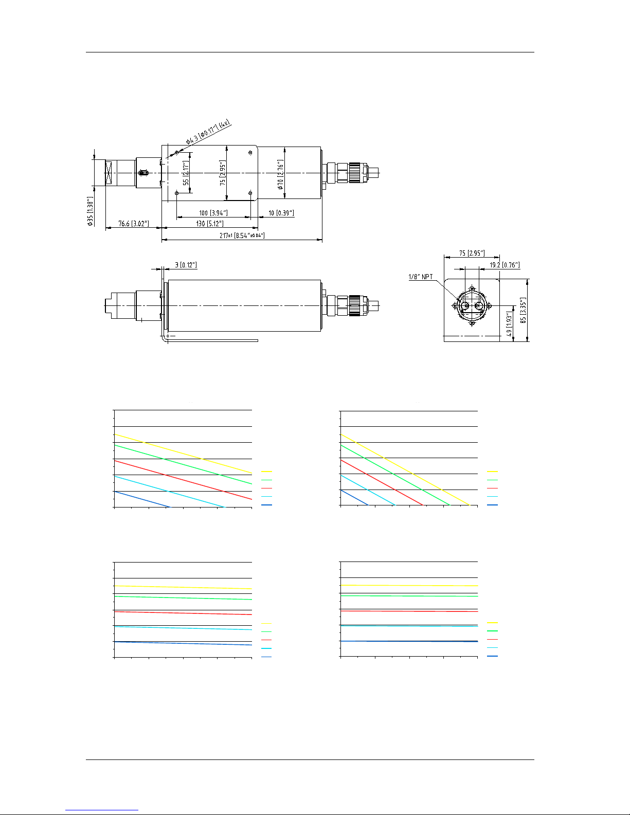
1.4 Measurements and flow charts of the mzr-2509 Ex pump
Figure 1 Measures of the micro annular gear pump mzr-2509 Ex
Liquid water Liquid methanol
0
2
4
6
8
10
0 1 2 3 4 5
Differential pressure [bar]
Flow rate [ml/min]
4700
4000
3000
2000
1000
Spee d [rpm]
Viscosity 1 mPa s
Liquid wa ter
0
2
4
6
8
10
0 1 2 3 4 5
Differential pressure [bar]
Flow rate [ml/min]
4700
4000
3000
2000
1000
Spee d [rpm]
Viscosity 0,58 mPa s
Liquid me thanol
Liquid oil, 16 mPas Liquid oil, 100 mPas
0
2
4
6
8
10
0 10 20 30
Differential pressure [bar]
Flow rate [ml/min]
4700
4000
3000
2000
1000
Spee d [rpm]
Viscosity 16 mPa s
Liquid oil
0
2
4
6
8
10
0
10
20 30
Differential pressure [bar]
Flow rate [ml/min]
4700
4000
3000
2000
1000
Spee d [rpm]
Viscosity 100 mPa s
Liquid oil
figure 2 Flow charts of the micro annular gear pump mzr-2909 Ex

1 General Information Operation manual mzr-2509 Ex/ mzr-2909 Ex / mzr-4609 Ex / mzr-7209 Ex
6 Technische Änderungen ohne Vorankündigung vorbehalten Last update: October 2016
1.5 Measurements and flow charts of the mzr-2909 Ex pump
Figure 3 Measures of the micro annular gear pump mzr-2909 Ex
Liquid water Liquid methanol
0
5
10
15
20
0 1 2 3 4 5
Differential pressure [bar]
Flow rate [ml/min]
4700
4000
3000
2000
1000
Spee d [rpm]
Viscosity 1 mPa s
Liquid wa ter
0
5
10
15
20
0 1 2 3 4 5
Differential pressure [bar]
Flow rate [ml/min]
4700
4000
3000
2000
1000
Spee d [rpm]
Viscosity 0,58 mPa s
Liquid me thanol
Liquid oil, 16 mPas Liquid oil, 100 mPas
0
5
10
15
20
0 10 20 30
Differential pressure [bar]
Flow rate [ml/min]
4700
4000
3000
2000
1000
Spee d [rpm]
Viscosity 16 mPa s
Liquid oil
0
5
10
15
20
0 10 20 30
Differential pressure [bar]
Flow rate [ml/min]
4700
4000
3000
2000
1000
Spee d [rpm]
Viscosity 100 mPa s
Liquid oil
figure 4 Flow charts of the micro annular gear pump mzr-2909 Ex

1 General Information Operating manual mzr-2509 Ex/ mzr-2909 Ex / mzr-4609 Ex / mzr-7209 Ex
Last update: October 2016 Technische Änderungen ohne Vorankündigung vorbehalten. 7
1.6 Measurements and flow charts of the mzr-4609 Ex pump
Figure 5 Measures of the micro annular gear pump mzr-4609 Ex (UOM: mm)
Liquid water Liquid methanol
0
10
20
30
40
50
60
70
80
0 2 4 6 8 10
Differential pressure [bar]
Flow rate [ml/min]
4700
4000
3000
2000
1000
609
Spee d [rpm]
Viscosity 1 mPa s
Liquid wa ter
0
10
20
30
40
50
60
70
80
0
2 4 6 8 10
Differential pressure [bar]
Flow rate [ml/min]
4700
4000
3000
2000
1000
609
Spee d [rpm]
Viscosity 0,58 mPa s
Liquid me thanol
Liquid oil, 16 mPas Liquid oil, 100 mPas
0
10
20
30
40
50
60
70
80
0
10 20 30 40 50
Differenzdruck p [bar]
Volumenstrom Q [ml/min]
4700
4000
3000
2000
1000
Drehza hl n [U/min]
Viskosität 16 mPas
Medium Öl
0
10
20
30
40
50
60
70
80
0 10 20 30 40 50
Differenzdruck p [bar]
Volumenstrom Q [ml/min]
4700
4000
3000
2000
1000
Drehza hl n [U/min]
Viskosi tät 100 mPa s
Medium Öl
figure 6 Flow charts of the micro annular gear pump mzr-4609 Ex
1 General Information Operation manual mzr-2509 Ex/ mzr-2909 Ex / mzr-4609 Ex / mzr-7209 Ex
8 Technische Änderungen ohne Vorankündigung vorbehalten Last update: October 2016
1.7 Measurements and flow charts of the mzr-7209 Ex pump
Figure 7 Measures of the micro annular gear pump mzr-7209 Ex
Liquid water Liquid methanol
0
50
100
150
200
250
300
0 10 20 30 40
Differential pressure [bar]
Flow rate [ml/min]
4700
4000
3000
2000
1000
09
Spee d [rpm]
Viscosity 1 mPa s
Liquid wa ter
0
50
100
150
200
250
300
0
10 20 30
40
Differential pressure [bar]
Flow rate [ml/min]
4700
4000
3000
2000
1000
09
Spee d [rpm]
Viscosity 0,58 mPa s
Liquid me thanol
Liquid oil, 16 mPas Liquid oil, 100 mPas
0
50
100
150
200
250
300
0 10 20 30 40
Differential pressure [bar]
Flow rate [ml/min]
4700
4000
3000
2000
1000
Spee d [rpm]
Viscosity 16 mPa s
Liquid oil
0
50
100
150
200
250
300
0 10 20 30 40
Differential pressure [bar]
Flow rate [ml/min]
4700
4000
3000
2000
1000
Spee d [rpm]
Viscosity 100 mPa s
Liquid oil
figure 8 Flow charts of the micro annular gear pump mzr-7209 Ex

1 General Information Operating manual mzr-2509 Ex/ mzr-2909 Ex / mzr-4609 Ex / mzr-7209 Ex
Last update: October 2016 Technische Änderungen ohne Vorankündigung vorbehalten. 9
1.8 Technical data of the Ex-motor
The micro annular gear pumps mzr-2509 Ex, mzr-2909 Ex, mzr-4609 Ex,
mzr-7209 Ex are equipped with an explosion-proof DC-motor. The parameters
of the motor are described in Table 2. The speed of the motor can be
controlled with the optional motion controller S-HD-KL. One of the motor’s
features is a highly dynamic behavior. For operation it is recommended to use a
power source of 24 V (with a power rating of 5 A).
The motor of the pumps is corresponding to the applicable EC standards. The
confirmations according to EC 94/9/EG as well as of EC conformity are given.
Measurements
Diameter of motor casing 70 mm
Length of motor casing
210 mm
Weight approx. 1,8 kg
General data
Type
EXR-1.24HEDL-L10
Manufacturer
Edelweiss Actuators Srl,
Via Padergnone 21
I-24050 Zanika BG
Italy
Distribution / Service
Mattke Antriebstechnik
Leinenweberstraße 12
D-79108 Freiburg
Germany
Test body 0948
Number of certificate
TÜV-A 11ATEX0006X
Certification
EN60079-0, EN60079-1, EU-
Richtlinie 94/9/EG, Anhang III
Ex-certification II 2G Ex d IIC T5 Gb
Installation place Ex-area zone 1, 2
Specification
Nominal voltage 24 V DC
Max. continuos current by
Temperature range T6
2 A
Max. continuos torque 75 mNm
Max. power
53 W
Max. dissipation 11 W
No load speed by 24 V 4700 rpm
Speed range
1 – 4700 rpm
Length of the cable 10 m
External compensation of potential
wires:
4 mm² flexible
6 mm² single-wire
Protective class according EN60529 IP54
Operation temperature range -20 … +45 °C
Table 2 Technical data Ex-motor

1 General Information Operation manual mzr-2509 Ex/ mzr-2909 Ex / mzr-4609 Ex / mzr-7209 Ex
10 Technische Änderungen ohne Vorankündigung vorbehalten Last update: October 2016
Parameter
mzr-2509 Ex
mzr-2909 Ex
mzr-4609 Ex
mzr-7209 Ex
Max. Peak current 800 mA 800 mA 900 mA 2000 mA
Max. Continuos current 600 mA 600 mA 700 mA 1800 mA
max. Acceleration
550 U/s²
550 U/s²
550 U/s²
550 U/s²
Table 3 Programming current parameters for mzr-2509 Ex, mzr-2909 Ex, mzr-4609 Ex and mzr-7209 Ex
Wire
Function
brown motor +
blue motor yellow/green screening / PE
red Vcc (5 VDC)
blue SGND
pink channel A neg.
grey channel A
yellow
channel B neg.
green channel B
brown channel O neg. (index)
white
channel O (index)
table 4 Pin configuration motor cable (10 Lead of cable) valid as of September 2012
Wire
Function
white motor +
brown motor -
yellow/green
screening / PE
red Vcc (5 VDC)
blue SGND
pink
channel A neg.
grey channel A
violet channel B neg.
black channel B
rot/blue channel I neg. (index)
pink/grey channel I (index)
Table 5 Pin configuration motor cable (10 Lead of cable) valid until September 2012

1 General Information Operating manual mzr-2509 Ex/ mzr-2909 Ex / mzr-4609 Ex / mzr-7209 Ex
Last update: October 2016 Technische Änderungen ohne Vorankündigung vorbehalten. 11
4 x M8, 8 mm deep
PUR - Drag chain cable
Type S200-Length 5...10 m
Figure 9 Measurements of the motor (standard cable length 10 m)
The motor is delivered with a digital encoder type HEDL5540 with line
driver and 500 counts per revolution.
Encoder
Max. voltage Vcc 5 VDC ± 10 %
Number of channels
3 (A, B, O)
Counts per revolution and channel 500
Output signal at V
cc
= 5 VDC EIA standard RS422
used driver: DS26LS31
Output current max. 20 mA
Phase shift Φ (nominal) 90°
Operating temperature range
0 ... +40°C
Table 6 Technical data encoder

1 General Information Operation manual mzr-2509 Ex/ mzr-2909 Ex / mzr-4609 Ex / mzr-7209 Ex
12 Technische Änderungen ohne Vorankündigung vorbehalten Last update: October 2016
1.9 Technical data of the altenativ brushless DC Ex-motor (X2 version)
The micro annular gear pumps mzr-6359X2 Ex and mzr-7259X2 Ex are
equipped with a alternativ explosion-proof brushless DC-motor. The parameters
of the motor are described in Table 2. The speed of the motor can be
controlled with the internal motion controller. One of the motor’s features is a
highly dynamic behavior. For operation it is recommended to use a power
source of 24 V (with a power rating of 5 A).
The motor of the pumps is corresponding to the applicable EC standards. The
confirmations according to EC 94/9/EG as well as of EC conformity are given.
Measurements
Diameter of motor casing 70 mm
Length of motor casing
285 mm
Weight approx. 2,3 kg (without cable)
General data
Type
EXR-32.24-MC3-L10
Manufacturer
Edelweiss Actuators Srl,
Via Padergnone 21
I-24050 Zanika BG
Italy
Distribution / Service
Mattke Antriebstechnik
Leinenweberstraße 12
D-79108 Freiburg
Germany
Test body 0948
Number of certificate
TÜV-A 11ATEX0006X
Certification
EN60079-0, EN60079-1, EU-
Richtlinie 94/9/EG, Anhang III
Ex-certification II 2G Ex d IIC T5 Gb
Installation place Ex-area zone 1, 2
Specification
Nominal voltage
24 V DC
Max. continuos current by
Temperature range T5
2 A
Max. continuos torque 85 mNm
Max. power
53 W
Max. dissipation 11 W
No load speed by 24 V 4200 rpm
Speed range
1 – 4000 rpm
Length of the cable 10 m
External compensation of potential
wires:
4 mm² flexible
6 mm² single-wire
Protective class according EN60529 IP54
Operation temperature range -20 … +40 °C
table 7 Technical data Ex-motor for mzr-2509X2 Ex, mzr-2909X2 Ex, mzr-4609X2 Ex und mzr-7209X2 Ex

1 General Information Operating manual mzr-2509 Ex/ mzr-2909 Ex / mzr-4609 Ex / mzr-7209 Ex
Last update: October 2016 Technische Änderungen ohne Vorankündigung vorbehalten. 13
Parameter
mzr-2509X2 Ex
mzr-2909X2 Ex
mzr-4609X2 Ex
mzr-7209X2 Ex
Max. Peak current 700 mA 700 mA 800 mA 1700 mA
Max. Continuos current 550 mA 550 mA 650 mA 1500 mA
max. Acceleration
500 U/s²
500 U/s²
500 U/s²
500 U/s²
Tabelle 1 Programming current parameters for mzr-2509X2 Ex, mzr-2909X2 Ex, mzr-4609X2 Ex und mzr-7209X2 Ex
Wire
Function
Cable cross-section
brown 24 VDC 0,5 mm²
blue GND 0,5 mm²
yellow/green screening / PE 0,5 mm²
red 3 IN 0,14 mm²
blue n.c. 0,14 mm²
white Fault out 0,14 mm²
pink n.c. 0,14 mm²
grey
AGND
0,14 mm²
yellow RxD / IN CAN_L 0,14 mm²
green TxD / IN CAN_H 0,14 mm²
brown
ANIN
0,14 mm²
table 8 Pin configuration motor cable (12 Lead of cable)

1 General Information Operation manual mzr-2509 Ex/ mzr-2909 Ex / mzr-4609 Ex / mzr-7209 Ex
14 Technische Änderungen ohne Vorankündigung vorbehalten Last update: October 2016
Figure 10 Measurements of the motor (standard cable length 10 m)

1 General Information Operating manual mzr-2509 Ex/ mzr-2909 Ex / mzr-4609 Ex / mzr-7209 Ex
Last update: October 2016 Technische Änderungen ohne Vorankündigung vorbehalten. 15

2 Safety instructions Operation manual mzr-2509 Ex/ mzr-2909 Ex / mzr-4609 Ex / mzr-7209 Ex
16 Technische Änderungen ohne Vorankündigung vorbehalten Last update: October 2016
2 Safety instructions
Comply with the general safety instructions listed in the safety section as well
as with the special safety instructions listed under the other main sections. All
legal and corporate safety instructions have to be obeyed.
2.1 Labeling of instructions in the operation manual
The safety instructions listed in this operation manual are specially labeled. It
can cause danger for persons, if they are not complied with.
Danger symbol
!
Non-compliance poses danger for
persons.
High voltage
symbol
Non-compliance poses danger of
electrical shock.
Ex-symbol
These instructions must be complied
with in full for explosion-protection.
The type plate mounted on the pump must be complied with and has to be
maintained in a clearly readable condition.
Please pay attention to items marked with the following symbols. Pump or
system damage is possible if these warnings are ignored.
Warning
Information plates attached directly to the pump head for example name of
the fluid inlet/outlet, sign with the direction of rotation must be observed and
preserved.
2.2 Staff qualification and training
The staff for operation, maintenance, inspection and assembly must evidence
appropriate qualifications for these works. Areas of responsibility, competencies
and monitoring of the staff must be precisely regulated by the operating
company. If the personnel do not have the necessary knowledge, they must be
trained and instructed accordingly. If necessary this can be carried out by the
manufacturer / supplier on behalf. In addition, the operating company must
ensure that the content of this operating manual is fully understood by the
personnel.

2 Safety instructions Operating manual mzr-2509 Ex/ mzr-2909 Ex / mzr-4609 Ex / mzr-7209 Ex
Last update: October 2016 Technische Änderungen ohne Vorankündigung vorbehalten. 17
2.3 Safety conscious work
The safety instructions listed in this operation manual, the applicable national
regulations for accident avoidance and all internal working, operating and
safety regulations of the operating company must be complied with.
2.4 Safety instructions for the operator
The surface temperature of the actuators can exceed 60°C (140°F) in full load.
You might want to provide protection to avoid accidental contact, which will
cause burns on skin.
The drive should be protected against dust, water vapor condensation,
humidity, splash water, aggressive gases and liquids. Please provide for
adequate air ventilation and thus cooling of the motor.
Leakage (e.g. from the shaft seal) of dangerous conveyed goods (e.g. explosive,
toxic, hot) must be lead away in such a manner that no danger is present for
persons and the environment. Legal requirements must be complied with.
The existing protections against contact for the moving parts of the pump (such
as for example the coupling) must not be removed during operation.
Take care that all risks resulting from the electric energy are excluded. (For
details please refer to the instructions provided by the authorities in charge or
your power supplier.)
Warning
Please insure, that the totality of the liquid supply accessories such as tubes,
hoses, filters etc. are free from dust or dirt particles. Impurities such as metal,
plastic or glass particles may impair or damage the pump leading to its failure.
Warning
Please, operate the pump with a filter featuring 10 µm or smaller pores. It will
protect the pump.

2 Safety instructions Operation manual mzr-2509 Ex/ mzr-2909 Ex / mzr-4609 Ex / mzr-7209 Ex
18 Technische Änderungen ohne Vorankündigung vorbehalten Last update: October 2016
2.5 Safety instructions for maintenance, inspection and assembly
The operator must ensure that all maintenance, inspection and assembly is
carried out by authorized and qualified personnel, who are sufficiently familiar
with this operation manual.
In general, work on the machine should only be implemented when it is at a
standstill. The instructions of the manual to shut down the pump must be
definitely observed. Pumps or aggregates that convey liquids hazardous to
health must be decontaminated. Immediately after operation is completed, all
safety and protection equipment must be remounted and restarted.
Before restart of operation, the points listed in the initial start-up section (see
section 7) must be observed.
Warning
Do not disassemble the micro annular gear pump in case of malfunction.
Contact the service personnel of your distributor or HNP Mikrosysteme
immediately for help.
When sending a micro annular gear pump for repair or maintenance the
»declaration of liquid contact« of the liquid pumped and the operation
statement from section 16 has to be enclosed in the shipment.
2.6 Unauthorized modification and original spare parts
Modification of the pump is only permitted prior to consultation with the
manufacturer. Original spare parts and accessories authorized by the
manufacturer ensure safety. The use of other parts may abolish the liability for
any resulting damage.
2.7 Improper mode of operation
The operation safety of the delivered machine is only ensured by its correct use
as per section 1 in this operation manual. The limit settings given in the manual
must not be exceeded in any case.

2 Safety instructions Operating manual mzr-2509 Ex/ mzr-2909 Ex / mzr-4609 Ex / mzr-7209 Ex
Last update: October 2016 Technische Änderungen ohne Vorankündigung vorbehalten. 19
2.8 General safety instructions
Please also obey the following safety notes.
!
Skilled personnel may only do mounting and initial operation of micro annular
gear pumps.
!
The pump can achieve high pressures. Use only the fluidic connections
included in the delivery and be sure, that fittings and tubes are permissible and
specified for these pressures.
!
In order to decrease the pressure, provide the system with a pressure control
valve directing the excess liquid to the storage tank or back to the suction side.
In the case of blockage of the pressure side the operating pressure can
multiply, this can lead to the damage of downstream components.
!
If standstill occurs, the liquid in the pump may float in direction of the pressure
drop in the pump. If necessary provide back pressure valves (see: accessories).
!
Protect the micro annular gear pump and the electric actuator from shock and
impact.
!
In standard operation the rotary shaft seals used in the micro annular gear
pump prevent leakage. Micro annular gear pumps are »technically sealed«,
but not hermetically sealed, so that gases may escape from the pump or
penetrate into the pump.
The permitted electrical data setting of the actuators may not be exceeded.
Notice that especially the accurate set of polarity of the supply voltage is
required, if not the control unit can be destroyed.
Warning
For the operation of a micro annular gear pump, the use of filters with a pore
size of 10 µm or smaller is required.
Warning
The preference state for the integration of the micro annular gear pump is
horizontal. To prevent a possible penetration of liquid in the motor, the motor
should be preferably assembled above the pump head.
Warning
It is necessary to check the liquid resistance in each individual case and to
adapt the seal equipment.

3 Transport and storage Operation manual mzr-2509 Ex/ mzr-2909 Ex / mzr-4609 Ex / mzr-7209 Ex
20 Technische Änderungen ohne Vorankündigung vorbehalten Last update: October 2016
3 Transport and storage
3.1 Shipping pumps and protection measures
The pumps are shipped from the factory in such a manner that they are
protected against corrosion and against shocks.
In addition, inlets and outlets are plugged with protective plugs. This measure is
necessary to securely prevent foreign bodies from penetrating into the pump’s
interior.
3.2 Transport damage
To avoid transport damage, the transport packaging must be protected against
shocks.
HNP Mikrosysteme guarantees that the shipped goods are in perfect condition
at the time of delivery. The pumps must be immediately checked for transport
damage once the pumps have been received. If damage is noted, the shipper
responsible and the pump manufacturer must be informed immediately.
3.3 Interim storage
The following points must be obeyed for storing the pumps:
− Do not store the pumps in wet or damp rooms
− Protective plugs must be left screwed in
− Store temperature see according section 1.3 of this manual
3.4 Conservation for storage after operation
When the micro annular gear pump operation is stopped for some time period
the pump has to be cleaned by flushing. See also chapter 7.6 for
decommissioning. When pump is clean it has to be filled with a preserving
liquid such as precision mechanic oil or Isopropyl alcohol.

4 Description of the pump Operating manual mzr-2509 Ex/ mzr-2909 Ex / mzr-4609 Ex / mzr-7209 Ex
Last update: October 2016 Technische Änderungen ohne Vorankündigung vorbehalten. 21
4 Description of the pump
4.1 Principle of the micro annular gear pumps
Micro annular gear pumps are positive displacement pumps. They contain two
rotors, bearing slightly eccentrically to each other; an externally toothed
internal rotor and an annular, internally toothed external rotor (see figure 11).
Due to their cycloid indenting, the rotors remain interlocked at any time,
forming during rotation a system of several sealed pumping chambers. As the
rotors revolve around their offset axis, the pumping chambers increase on the
induction (suction) side and simultaneously decrease on the delivery side of the
pump (see figure 12). A homogenous flow is generated between the kidneylike inlet and outlet.
internal
rotor
external
rotor
delivery sideinduction side
inlet outlet
figure 11 Principle of the micro annular gear pump
figure 12 Operating principle of the micro annular gear pump
Reciprocating and rotary pumps have a direct allocation to the fed amount of
the displacement volume V
g
of the pump and its actuator’s number of
revolutions n. The displacement volume describes the volume, which is
theoretically fed with each revolution. The coherence of the flow rate referring
to the formula (= volumetric flow rate) Q of the pump is:
nVQ
gVol
⋅⋅=
η
The volumetric efficiency
η
Vol
describes the coherence of the actual flow rate
from the theoretical resulting value. Differences occur according to leaking, as
the sealing on the inside of the pump is done over a gap. The volumetric

4 Description of the pump Operation manual mzr-2509 Ex/ mzr-2909 Ex / mzr-4609 Ex / mzr-7209 Ex
22 Technische Änderungen ohne Vorankündigung vorbehalten Last update: October 2016
efficiency is dependent on the liquids and the pressure against which it has to
be fed.
Example: The pump mzr-2909 Ex feeds with its displacement volume of 3 µl
with 3000 RPM and a volumetric efficiency of 100 % referring to the abovementioned formula the flow rate of 9 ml/min. The following table shows the
volumetric displacement in dependence to the number of revolutions for a
volumetric efficiency of
η
Vol
= 100 %.
mzr-2509 Ex mzr-2909 Ex mzr-4609 Ex mzr-7209 Ex
speed
[rpm]
Q
[ml/min] Q [ml/h] Q [ml/min]
Q
[ml/h]
Q
[ml/min]
Q
[ml/h]
Q
[ml/min] Q [ml/h]
500 0,75 45 1,5 90 6 360 24 1440
1000 1,5 90 3 180 12 720 48 2880
2000 3 180 6 360 24 1440 96 5760
3000 4,5 270 9 540 36 2160 144 8640
4000 6 360 12 720 72 2880 192 11520
Table 9 Theoretical flow rate of the micro annular gear pump mzr-2509 Ex, mzr-2909 Ex, mzr4609 Ex or mzr-7209 Ex
The pressure, which the pump has to generate, is given by the construction of
the fluidic system and the results of the hydrostatic pressure and the hydraulic
resistance (given by tubes, contractions etc.).
The viscosity of the pumping liquid has an important influence on the
volumetric efficiency. The volumetric efficiency increases with higher viscosity
according to the smaller disengagement through the gaps of the pump.
Cavitation is an effect, which can reduce the volumetric efficiency from in a
specific ceiling speed. With increasing viscosity (e.g.> 5.000 mPas), this ceiling
speed is lower. This is the result of the liquids specified underflow of the steam
pressure in the induction port of the pump, in which gases are building up in
the pump.
The specific feature of the
mzr-pumps is their highly precise design, as well as
the guarantee of high accumulator pressure and high accuracy in flow rate and
dosage. Therefore, space width and transverse space width of the rotors as well
as the interspace to the adjacent case parts lie in the range of just a few
micrometers. This precession is at the same time the criteria to achieve a
volumetric efficiency in the range of approximately 100 %.

4 Description of the pump Operating manual mzr-2509 Ex/ mzr-2909 Ex / mzr-4609 Ex / mzr-7209 Ex
Last update: October 2016 Technische Änderungen ohne Vorankündigung vorbehalten. 23
4.2 Construction
The micro annular gear pumps mzr-2509 Ex, mzr-2909 Ex, mzr-4609 Ex and
mzr-7209 Ex consist out pump head, coupling assembly and motor with cable
gland. The micro annular gear pump has a bracket to the simple fastening.
cable gland
motor
bracket
coupling assembly
pump head
outlet
inlet
figure 13 Design of the micro annular gear pumps mzr-2909 Ex and mzr-4609 Ex (mzr-7209 Ex similar illustration)
4.3 Materials and liquids
Wetted parts mzr-2909 Ex, mzr-4609 Ex mzr-7209 Ex
Pump housing stainless steel 316 L (1.4404, 1.4435) stainless steel 316 L (1.4404, 1.4435)
Rotors, shaft, bearing tungsten carbide Ni-based tungsten carbide Ni-based
Shaft sealing
graphite-reinforced PTFE,
316L spring
graphite-reinforced PTFE,
316L spring
Static sealing
FKM,
optional: EPDM, FFKM
FKM,
optional: EPDM, FFKM
table 10 Construction materials of the wetted parts
!
The liquid resistance of the materials has to be checked and guaranteeing
before the operation by the operator.
The liquid resistance has to be checked in every individual case. The feeding of
non-lubricant liquids reduces the service life of the micro annular gear pump.
This is also true for liquids containing particles.

4 Description of the pump Operation manual mzr-2509 Ex/ mzr-2909 Ex / mzr-4609 Ex / mzr-7209 Ex
24 Technische Änderungen ohne Vorankündigung vorbehalten Last update: October 2016
4.4 Fluidic connectors
Liquid inlet/outlet Tubing
mzr-2909 Ex,
mzr-4609 Ex
1/4"–28 UNF, front
OD 1/8" plastic tubes or stainless steel
tubes (optional outer diameter 1/16")
mzr-7209 Ex
lateral 1/8" NPT internal thread
front 1/8" NPT internal thread
tube/hose OD 6 mm
table 11 Liquid supply
The liquid inlet is marked with the letter »S«, the liquid outlet connection with
the letter »D«. An arrow indicates the inherent turning direction of the shaft.
For protection against penetrating dust particles and contamination, sealing
plugs are inserted into the threads. The sealing plugs have to be removed
before the assembly of the fluidic connectors. Please reseal the threads with the
cleaned sealing plugs when the fluidic connectors are disassembled.
The assembled fluid connectors have to be checked immediately after bringing
the pump into operation. This is also true for service in a half-yearly cycle on
tightness and leakage.

5 Modular system Operating manual mzr-2509 Ex/ mzr-2909 Ex / mzr-4609 Ex / mzr-7209 Ex
Last update: October 2016 Technische Änderungen ohne Vorankündigung vorbehalten. 25
5 Modular system
The spectrum of applications of the high performance micro annular gear
pump series may be expanded by using different additional modules. The
modules allow for special applications, which could otherwise not be
accomplished with a standard pump version. The modules may be combined
with each other and with almost all available pump heads.
− Fluidic seal module prevents possible chemical reactions between the
delivered liquid and the surrounding environment
− Heat insulation module extends the operating temperature range of the
pump by protecting the motor from overheating
− Heating module enables to regulate the temperature of the fluid-containing
parts of the pump
− Gas-tight sealed version: almost hermetically sealed pump, delivered as
standard with the high performance mzr-pumps
The configuration of a given pump version should in each case be discussed
with consideration to the specific requirements of the application. Additional
customized modules may be designed on demand.
5.1 Fluidic seal module
cable gland
motor
bracket
coupling assembly
pump head
outlet
inlet
fluidic seal module
figure 14 Design of the micro annular gear pump mzr-4609 Ex with fluidic seal module
The module can be applied for liquids which tend to react or crystallize in
contact with gases such as oxygen or water. The use of a fluidic seal module
has to be confirmed with the pump manufacturer.

5 Modular system Operation manual mzr-2509 Ex/ mzr-2909 Ex / mzr-4609 Ex / mzr-7209 Ex
26 Technische Änderungen ohne Vorankündigung vorbehalten Last update: October 2016
Functioning of fluidic seal module
Based on the pump design in the rotary shaft seal there is a liquid boundary
film where the liquid is in contact with the ambient. Here small amounts of
ambient humidity or oxygen can penetrate into the pump getting over the
sealing lip. To prevent penetrating molecules from outside into the pump but
also hazardous substances coming out of the pump the fluidic seal module was
designed.
For this reason a second rotary seal is added to the pump which is located in
the fluidic seal module. Between the two rotary seals a fluidic chamber (see
figure 15) is formed which is filled with a sealing liquid compatible to the
pumped liquid. The fluidic seal module has two ports opposite to each other
for filling and degassing. A pressure head can be applied to the sealing liquid to
assure a support of the sealing function. In certain cases the sealing can be
flushed.
The sealing liquid will dilute the pumping liquid during operation with a
dilution ratio of approx. 1:1,000,000. The sealing liquid has to be compatible
with the delivered liquid and has to be determined in interdependence. A
cartridge can be used as a reservoir and is sufficient at maximum flow for one
month in most cases.
fluidic chamber
figure 15 Sectional view of the micro annular gear pump with fluidic seal module
Operation with fluidic seal module
The selected sealing liquid has to be compatible with the delivered liquid. The
customer is in charge of the correct selection.
The filling procedure through the port has to be realized carefully. The ports
have a 1/4"-28 UNF thread. They are displaced to realize a better degassing of
the seal chamber also in a horizontal direction. The filling of the sealing liquid
starts with the lower level port. The filling of the fluidic seal module continues
until no bubbles can be seen on the outlet port side. When the liquid is free of

5 Modular system Operating manual mzr-2509 Ex/ mzr-2909 Ex / mzr-4609 Ex / mzr-7209 Ex
Last update: October 2016 Technische Änderungen ohne Vorankündigung vorbehalten. 27
bubbles the outlet port has to be closed by vent screw. To fill the chamber a
cartridge or syringe with an appropriate thread 1/4"-28 UNF can be used.
seal liquid inlet
seal liquid outlet
figure 16 Sectional view of the fluidic seal module
!
Please note that the cartridge or syringe has to be filled up always with
sufficient sealing liquid to avoid air or moisture contact.
In case of installation within explosion proof areas a level control for the
reservoir of the seal liquid is necessary to avoid dry running of the pump.
If the fluidic seal module is empty the pump must shut down immediately.
If a different installation is selected than the standard installation (e.g. pump
marking horizontal readable) it is possible to exchange the seal liquid inlet port
and outlet port.
The cartridge always has to be assembled in a vertical way to guarantee that
the liquid is gas free and can refill the sealing chamber.

5 Modular system Operation manual mzr-2509 Ex/ mzr-2909 Ex / mzr-4609 Ex / mzr-7209 Ex
28 Technische Änderungen ohne Vorankündigung vorbehalten Last update: October 2016
5.2 Heat insulation modul
The heat insulation module enables to deliver hot liquids up to temperatures of
130° C (266 °C). It comprises thermally insulating coupling components made
of plastic (PEEK) located between the pump and the drive. The drive should not
be exposed to overheating. For this reason the heat transfer from the pump to
the drive should be limited. An additional thermal barrier is provided by the
plastic motor housing. If the surrounding temperature rises, the pump is
working over a longer period or the manipulated liquid features a high
temperature, convection cooling of the motor is recommended.
Earth the pump head additionally at the corresponding terminal clamp.
The pump carries the changed identification with the non insulating coupling
components and the higher temperature:
CE
II 2G c IIC T3 X
Description of the single symbols:
Equipment meets the requirements of the RL 94/9/EG
II Equipment of the group of equipment II („Non-mining industry“)
2G Equipment of the category 2, intended for the employment in zone
1 (explosion endangerment by inflammable gases, steams or
nebulas), can be used also in zone 2
c As explosion prevention measure the ignition enclosure was
converted „constructional security“(c) according to EN 13463-5.
IIC The equipment fulfills the requirements for the employment within
highly combustible ranges, within which the explosion
endangerment can be due to materials of the explosion group IIC
(like e.g. hydrocarbons).
T3 The equipment fulfils the requirements to that temperature class T3.
X For the safe employment of the equipment within highly
combustible ranges special conditions are to be considered.

5 Modular system Operating manual mzr-2509 Ex/ mzr-2909 Ex / mzr-4609 Ex / mzr-7209 Ex
Last update: October 2016 Technische Änderungen ohne Vorankündigung vorbehalten. 29
5.3 Fluidic heating- and cooling module
The fluidic heating and cooling module permits active heating or cooling of the
pump head in the operating temperature range from -20 °C (-4 °F) to a
maximum of 150 °C (266 °F). The module consists of a double casing covering
the pump head and a thermoelectric couple type K, whose mode of integration
varies depending on the pump size. Oil, water, superheated steam or adapted
cooling liquids may be used as thermal liquids. If you are not sure, which heat
transfer liquid is the best adapted in your case, HNP Mikrosysteme will help you
find the suitable one. The thermal liquid ports 2 x G1/8" are displaced by 45°.
The inlet for the heat transfer liquid is situated at the back (beveled) and the
outlet is in the front (see figure 17).
heat transfer liquid
outlet
thermoelectric couple
double casing
liquid inlet
(suction side)
heat transfer liquid
inlet
liquid outlet
(delivery side)
figure 17 Micro annular gear pump with integrated fluidic heating- and cooling module (example of mzr-4609 EX)
!
The heating and cooling module is approved for use in EEx areas
Earth the pump head additionally at the corresponding terminal clamp.
!
Before connecting the liquid supply, please observe the following technical
data! The maximal pressure of the heat transfer liquid should not exceed
20 bar.

5 Modular system Operation manual mzr-2509 Ex/ mzr-2909 Ex / mzr-4609 Ex / mzr-7209 Ex
30 Technische Änderungen ohne Vorankündigung vorbehalten Last update: October 2016
Thermal element
IEC 584.3
identification
Type Thermocoax:
4ABAo15/35mm/TI/D5
0/4ABAB40T/12m –
ATEX EExia IIC T6
_
+
+
_
Thermal element
2 Thermal elements
Typ K (NiCr-Ni;
Chromel-Alumel)
Temperature measuring range
-100 to +400 °C
(-148 to 752 °F)
Diameter of the sensing device approx. 1.5 mm
Material V4A (1.4541)
Length compensating circuit 12 m
Diameter compensating circuit 4 mm
Double jacket mzr-2909 Ex mzr-4609 Ex mzr-7209 Ex
Length
34.25 mm
37.0 mm
37.5 mm
Diameter 42.4 mm 42.4 mm 48.3 mm
Double jacket material stainless steel 316L stainless steel 316L stainless steel 316L
Inlet
2xG1/8“ (45°
distance)
2xG1/8“ (45° distance) 2xG1/8“ (45° distance)
Operating temperature range
-20 to +150 °C
(-4 to +266 °F)
-20 to +150 °C
(-4 to +266 °F)
-20 to +150 °C
(-4 to +266 °F)
Max. pressure max. 20 bar max. 20 bar max. 20 bar
Flow rate max. 0.5 l/min max. 0.5 l/min max. 0.5 l/min
table 12 Technical data of the heating and cooling module
The pump carries the changed identification with the non insulating coupling
components and the higher temperature:
CE
II 2G c IIC T3 X
Description of the single symbols:
Equipment meets the requirements of the RL 94/9/EG
II Equipment of the group of equipment II („Non-mining industry“)
2G Equipment of the category 2, intended for the employment in zone
1 (explosion endangerment by inflammable gases, steams or
nebulas), can be used also in zone 2
c As explosion prevention measure the ignition enclosure was
converted „constructional security“(c) according to EN 13463-5.
IIC The equipment fulfills the requirements for the employment within
highly combustible ranges, within which the explosion
endangerment can be due to materials of the explosion group IIC
(like e.g. hydrocarbons).

5 Modular system Operating manual mzr-2509 Ex/ mzr-2909 Ex / mzr-4609 Ex / mzr-7209 Ex
Last update: October 2016 Technische Änderungen ohne Vorankündigung vorbehalten. 31
T3 The equipment fulfils the requirements to that temperature class T3.
X For the safe employment of the equipment within highly
combustible ranges special conditions are to be considered.
5.3.1 Construction materials of heating- and cooling module
Wetted parts
mzr-2909 Ex, mzr-4609 Ex
mzr-7209 Ex
Pump case material stainless steel 316L (1.4404) stainless steel 316L (1.4404, 1.4435)
table 13 Construction materials of the wetted parts
!
The resistance of the construction materials to the delivered liquids should be
verified by the operator for each individual application of the heating and
cooling module.
The chemical resistance of seals in each individual must be verified by the
operator.
5.4 Gas-tight seal module
Micro annular gear pumps are „technical tight“, but not hermetical tight. That
means there is a small possibility of gas or liquid coming out from inside of the
pump or also penetrating into the pump between the inner plates of the
structure. These plates have a super finish surface so that they are tight when
layered over each other.
For the Ex-pump additional O-rings are mounted between the plates to
increase the safety of thightness. With the gas-tight module and the fluidic seal
module micro annular gear pumps are nearly hermetical tight.
The micro annular gear pumps mzr-2909 Ex, mzr-4609 Ex and mzr-7209 Ex will
be delivered in a gas-tight version in every case.

6 Mounting / Installation Operation manual mzr-2509 Ex/ mzr-2909 Ex / mzr-4609 Ex / mzr-7209 Ex
32 Technische Änderungen ohne Vorankündigung vorbehalten Last update: October 2016
6 Mounting / Installation
6.1 Check before installation
Inspect pumps for possible shipment damage.
Verify the following points to ensure the pump head is correct for your
application (see section 3.2).
− Viscosity range of pumping liquid
− Displacement volume
− Flow rate
!
If there is a difference between the pump you need and the pump supplied,
please contact your distributor or HNP Mikrosysteme directly. In this case do
not start operation of the pump without checking with HNP Mikrosysteme.
You must check not only the type of protection of the pump, but also the type
of protection of all attached components. The nameplates of the individual
components are important. The type of protection for the component with the
lowest category always applies for the operation of all components in
hazardous areas.
6.2 Details place of operation
Pay attention to the place of operation, that you need an installation location
for service and enough room for maintenance. The pump should be installed
and reinstalled without problems.
The place of operation mustn't be wet or damp. Don't install the pump in
aggressive atmosphere!
6.3 Mounting of the micro annular gear pump
For the mounting of the micro annular gear pump there is a mounting angle to
be fastened with four stainless steel M4 screws. The preferred mounting
direction of the pump is horizontal. For vertical mounting the preferred
direction is where the motor is above the pump head.
To prevent a possible penetration of the motor with escaping liquid, the drive
should be preferably assembled vertically over the pump head.
When mounting the motor, insulating elements must not be inserted between
the pump head and the motor. The connecting screws between pump and
motor must be made out of electrically conductive material
(e.g. stainless steel).

6 Mounting / Installation Operating manual mzr-2509 Ex/ mzr-2909 Ex / mzr-4609 Ex / mzr-7209 Ex
Last update: October 2016 Technische Änderungen ohne Vorankündigung vorbehalten. 33
Warning
Take care at the mounting of the micro annular gear pump that in the fault
case leaking liquid cannot get into the motor or the control unit.
!
Take caution measures in the case of a leak so, that damage to adjacent
facilities and the ambient environment are avoided.
Never install a pump in a small installation location without sufficient
ventilation as the motor will be poorly cooled and can overheat.
!
The actuators must be protected against moisture, dust and perspiration.
6.4 Electrical Connections
The electrical connection of the motors must be implemented according to
VDE directives by skilled personnel. The operation manual supplied with the
motors must also be complied with.
Earth the motor using the terminal provided.
Earth the pump head with
heating module additionally at the corresponding terminal clamp.
6.5 Assembly instruction for tubing and accessories
Particles or soiling can block or impair the function of the micro annular gear
pump.
Warning
Please check that all wetted parts of the fluidic system are clean. Clean these
parts in case before mounting the pump.
Please check whether there are swarfs in the screw connections, pollution
remaining in reservoirs or soiling in valves, pipe work or filters.
Assembly of the tubing and piping system
1. Please cut the tubing rectangular with a hose cutter.
2. If metal pipes are used an intensive cleaning procedure is necessary. After
machining the pipes have to be cleaned and flushed very carefully. Smallest
swarfs within the fluidic system can cause failure of the micro annular gear
pump.
3. Connect the fittings with the tubing respectively the pipe work according to
the attached installation instruction.
4. In the next step seal the pipe fittings at the suction side and discharge side
of the pump head with PTFE tape. This is only valid for 1/8“ NPT inside
thread.
5. The thread of the fitting should be wrapped with 2-3 layers of PTFE tape
and screwed in the NPT thread (see table 15). First manually, then tightened
with ½ to ¾ wrench turns.

6 Mounting / Installation Operation manual mzr-2509 Ex/ mzr-2909 Ex / mzr-4609 Ex / mzr-7209 Ex
34 Technische Änderungen ohne Vorankündigung vorbehalten Last update: October 2016
Clean the internal and external
screw threads leaving no residues.
Make sure the internal and
external screw threads are not
dented or deformed.
Wrap the PTFE tape around the screw
thread clockwise beginning with the
second pitch of screw thread..
The PTFE tape should be wrapped
tightly around the screw thread
approx. two times (720°).
Cut the PTFE tape off and wind
the end of the tape tightly around
the screw thread.
The PTFE tape should not stick out over
screw thread because pieces can be
cut off and get into the system.
table 14 Use of PTFE Tape
!
Please note that the correct assembly of tubes respectively pipes with the
pump head is a necessary condition to secure the right direction of flow.
When you want to operate the pump in reverse direction please contact
HNP Mikrosysteme since this is not possible in any application.
6. The suction line should be installed ascending to the pump for better
degassing. The suction line should be designed as short as possible. The
inner diameter of the suction line should be large to guarantee good
priming of the liquid. At the planning of the pipe system take care of
possibilities for degassing.
7. Operate the micro annular gear pump always with a filter with a pore size
of 10 µm or smaller. The filter prevents that particles or solids penetrate
into the pump what can cause major damage.
8. Avoid dry running of the pump. Make sure that the liquid flow is not
interrupted.
Warning
Dry running of a micro annular gear pump can damage bearings and dynamic
seals especially. A short term dry running at the start-up of the pump does not
cause problems.

6 Mounting / Installation Operating manual mzr-2509 Ex/ mzr-2909 Ex / mzr-4609 Ex / mzr-7209 Ex
Last update: October 2016 Technische Änderungen ohne Vorankündigung vorbehalten. 35
Warning
The pump is equipped with a dynamic seal and a direct drive. Therefore the
pump is not hermetic from a technical point of view. That’s why it is
periodically necessary to check the pump regarding leakage.
Please check that all pipes, fittings and screw fittings are tight.
If there is leakage on the suction side it is possible that air penetrates into the
pump. In this case priming will be difficult. At the discharge side the liquid
comes out of the pump. Dry running causes the pump to heat up.
If the pump will be operated within an explosion proof area a check valve right
must be integrated in the pressure line behind the liquid outlet port of the
pump. The check valve has to prevent that the pump empties during shutdown time.
Behind the discharge port the discharge pipe should be installed ascending..
In case the pump operates against a closed system a safety valve has to be
installed in the discharge pipe to release pressure. In this case the return flow
pipe must go back to the reservoir and not directly to the suction line.
6.6 Filter selection and use
In majority of cases it is recommended to integrate a filter on the suction side
of the micro annular gear pump to ensure its secure operation. The
recommended filter pores or mesh size should not exceed 10 µm. The
penetration of particles or swarf that could cause a blockage or damage to the
pump can only be avoided by using an adapted filter.
HNP Mikrosysteme offers a choice of standard filters covering a broad spectrum
of applications. You may count on our assistance for the selection of the most
suitable one.
In order to select the best adapted filter, such operating parameters as flow
rate, viscosity and degree of pollution of the liquid will be needed. An increase
in at least one of the mentioned terms will require the use of a bigger filtering
element or the pressurization of the delivered liquid. In case no suitable filter
for high viscosity liquid can be found, it is possible to use a filter with slightly
larger pore size. Prior discussion with HNP Mikrosysteme is here recommended.
A filter with larger pores is still better than no filter at all. Alternatively an
already filtered liquid may be used.
Warning
Because filters have a large internal volume, it is recommended to fill in the
filter and the suction tube with already filtered liquid in order to avoid a longer
dry operation of the pump during the startup.
Warning
Please control regularly the filtering elements for pollution. Cleanse regularly
the filter or replace it with a new one. A polluted filter may considerably
decrease the volumetric efficiency of a pump. Furthermore, because of the
cavitation effects dosage imprecision and even pump damage may occur.
Warning
A too small filter (too little filtering surface) may considerably decrease the
volumetric efficiency of the micro annular gear pump. What is more, because
of the cavitation effects dosage imprecision and even pump damage may
occur.

6 Mounting / Installation Operation manual mzr-2509 Ex/ mzr-2909 Ex / mzr-4609 Ex / mzr-7209 Ex
36 Technische Änderungen ohne Vorankündigung vorbehalten Last update: October 2016
6.7 Requirements for motor controller
To operate a micro annular gear pump mzr-2509 Ex, mzr-2909 Ex,
mzr-4609 Ex or mzr-7209 Ex a motion controller is necessary.
Motion controller
Power supply UB 24 V
Max. continuous current I
dauer
1800 mA
Max. peak current I
max
2000 mA
Velocity range
1...4700
rpm
Operation modes IxR, Encoder
Encoder
Max. voltage
Vcc
5 ± 10 %
VDC
Number of channels 2 (channel A, channel B)
Counts per revolution and
channel
500 counts/turn
Output signal at V
cc
= 5 VDC EIA Standard RS422
Driver: DS26LS31
Output current max. 20 mA
Phase shift Φ (nominal)
90°
Table 15 Technical data motor controller
The mounting place of the motor controller has to be outside of the Ex-area.
Check for correct polarity. False connection may cause severe malfunction or
will even destroy the electronic of encoder or motion controller.
For operation of the motor controller current overload has to be avoided,
because the motor or the internal encoder will be damaged otherwise.
Optionally the micro annular gear pump mzr-2509 Ex, mzr-2909 Ex,
mzr-4609 Ex and mzr-7209 Ex can be delivered with the controller S-HD-KL
together with connection board.
To operate a micro annular gear pump only an authorised control module of
HNP Mikrosysteme may be used.

6 Mounting / Installation Operating manual mzr-2509 Ex/ mzr-2909 Ex / mzr-4609 Ex / mzr-7209 Ex
Last update: October 2016 Technische Änderungen ohne Vorankündigung vorbehalten. 37
6.8 Operation with motion controller S-HD-KL
The mounting place of the motor controller S-HD-KL has to be outside of the
Ex-area.
The controller S-HD-KL controls the number of revolutions to achieve a
constant flow rate or positions the motor for precise dosage volumes. Values
can be set with the help of a potentiometer or with the external control signal
0-10 V. Second a serial interface allows the control of precise feeding and
dosing tasks by an external PC. Included in the delivery volume are diskettes
with a Windows
®
based software. The software enables the operator to
manage dosing tasks by defining dosing data. A zero modem cable is included
in the delivery volume to connect the pump controller S-HD-KL with a PC.
Controller S-HD-KL
Type of control unit
4-Q servo amplifier
Nominal voltage U 24 V
Power supply UB 12 - 30 V
Residual ripple
≤
2 %
Nominal voltage U 24 V
Power supply UB 12 - 30 V
Max. continuous output current I
continuous
1800*) mA
Max. peak output current
I
max
2000*)
mA
Speed range 10...4700*) rpm
Input No. 1 input resistance 5 kΩ
Nominal analog speed
voltage range
± 10
V
Nominal digital speed PWM signal low 0...0.5 / high 4...30 V
frequency range 100...2000 Hz
Input/output No. 2
Error signaling
max. UB / 30 mA
(progammable) no error switched to GND
programmed as input low 0...0.5 / high 3,5... UB V
Input No. 3, 4, 5
TTL - logic level
low 0...0.5 / high 3,5...30
V
PLC - logic level low 0...7 / high 12,5...30 V
Program memory 6,6 kBytes
*) Values limited in the control unit with corresponding software
Table 16 Technical data controller S-HD-KL

6 Mounting / Installation Operation manual mzr-2509 Ex/ mzr-2909 Ex / mzr-4609 Ex / mzr-7209 Ex
38 Technische Änderungen ohne Vorankündigung vorbehalten Last update: October 2016
motor cable
pumps
mzr-2909 /mzr-4609 / mzr-7209 Ex
speed regulation
serial interface of PC
external voltage supply
24 V DC / 2.5 A
Status LED
+
-
switch S1
Figure 18 Connection schema controller S-HD-KL
The connection board is helpful for bringing into service of the micro annular
gear pump easily. It comprises the following interfaces:
− the possibility to connect the voltage supply to the delivered DIN socket
− the possibility to connect the voltage supply with screw clamps
− a 10-pole connector assembly for the motor cable
− speed set with potentiometer
− analog voltage signal 0-10 V for speed control at the screw clamps
− 9-pole connection plug for the RS-232 interface
− error output with status LED, programmable also as trigger input with screw
connections
− tumbler switch S1 for the connection of digital input No. 3 of the motor
control unit
− screw clamps for the connection of digital inputs No. 3, 4, 5 of the motor
control unit
Initial operation procedure
1. Connect the motor cable with the board S-HD-KL. Colour settings of wires
see Table 18.
Pin controller S-HD-KL
Function
white motor +
brown motor -
yellow/green
screening / PE
red Vcc (5 VDC)
blue SGND
pink
channel A neg.
grey channel A
violet channel B neg.
black channel B
rot/blue channel I neg. (index) (not in used)
pink/grey channel I (index) (not in used)
Table 17 Pin configuration motor cable adapter (10 Lead of cable) from motor to controller S-HD-KL
(8 Lead of cable see 1.8)

6 Mounting / Installation Operating manual mzr-2509 Ex/ mzr-2909 Ex / mzr-4609 Ex / mzr-7209 Ex
Last update: October 2016 Technische Änderungen ohne Vorankündigung vorbehalten. 39
2. Connect the RS-232 connector of the MCDC2805 with a free serial
interface of a PC. Apply the 9-pin zero-modem cable, included in the
delivery volume.
3. Turn the potentiometer on the S-HD-KL to zero position by shifting
clockwise to the right stop.
4. Connect the voltage supply 24 VDC. This can be done with the integrated
DIN connector or alternatively the 2-pole screw clamp (24 V = »+«;
GND = »-«). Pay attention to the correct polarity.
Check for correct polarity. False connecting may cause severe malfunction or
even destroy the electronic of the control unit.
The mounting place of the motion controller is intended for use outside of the
hazardous areas only.
Explanation:
− It is possible to adjust speed of the micro annular gear pump with the
potentiometer without the need to connect the serial interface.
− With the analog nominal value input (connection clamps »AnIN« and
»GND«) it is possible to adjust speed of the pump with a standard signal
0-10°V. For this purpose it is necessary to plug the jumper on the S-HD-KL
control unit from the »AnalogPoti« to the »AnalogExtern«. The serial
interface does not need to be connected.
− In case of an overcurrent error the green status LED on the S-HD-KL control
unit turns red
− The standard programs memorized in the motor control unit may be started
with the tumbler switch S1.
5. Install the software »Motion Manager« described in the next chapter.

6 Mounting / Installation Operation manual mzr-2509 Ex/ mzr-2909 Ex / mzr-4609 Ex / mzr-7209 Ex
40 Technische Änderungen ohne Vorankündigung vorbehalten Last update: October 2016
6.9 Connection of the micro annular gear pump with S-G05
In order to operate the pump a supplementary source of 24 VDC will be
required. The ampacity of the voltage source should amount to around 4 A for
the micro annular pumps mzr-2509X2 Ex, mzr-2909X2 Ex and mzr-4609X2 Ex.
The ampacity of the voltage source should amount to around 4 A for the micro
annular pump mzr-7209X2 Ex
The mounting place of the motion controller is intended for use outside of the
hazardous areas only.
The micro annular gear pump with alternativ brushless DC Ex-motor is
connected via the Terminal Box S-G05. This enables an easy startup of the
pump due to:
− the possibility to connect the voltage supply with the delivered plug
connector J1
− alternative voltage supply via a DIN connector conform with DIN 45323
− separable pump connection "mzr-pump"
− speed set via potentiometer
− analog voltage input 0-10 V and 0 (4)-20 mA for speed control
− change of speed setting mode with a DIP-switch
− 9-pole connection plug for the RS-232 interface
− error output programmable also as trigger input or frequency output
− digital input with a screw connection
− possibility of installation on a 35 mm top hat rail
79
90
100
100
69
92
90
69
79
4x Ø3,2
ON
1 2 3 4
ON
1 2 3 4
ON
1 2 3 4
0(4).. .20 m A
0... 10 V
Poti
Mode
Speed
Stat us
Ready: green
Fault: red
9
Dig
. I
npu
t
TxD 1
6
15 RxD13
Analog
GND
Fa
ult Ou
t 14
An alog
In.
12
24 V
DC
10
11 G
ND
Terminal Box S-G05
HNP Mikrosyst eme GmbH
RS-232 P ower I n
24 VDC
0
1
2
4 V
DC
/ 4A
Dig.
In
put
8
7
Fa
ult
5
A
nal
og
In.
GN
D
6
n.c.
4
G
ND
2
3
1
0 V
out
ON
1 2 3 4
ON
1 2 3 4
ON
1 2 3 4
0(4).. .20 m A
0... 10 V
Poti
Mode
Speed St atus
Ready: green
Fault: red
D
ig.
Inp
ut
16 RxD
Anal
og GND
141210
GND
Terminal Box S-G05
HNP Mikrosyst eme GmbH
RS-232 P ower I n
24 VDC
24
VDC
/
4A
FaultAn
alog
In
.
10
V o
ut
TxD
Faul
t Out
Analog
In.
2
4 V
DC
151311
9
1
753
D
ig.
In
put
GN
D
n.c.
GND 2
864
0
mzr-pumpJ2power / signal
J1
26
47
18
2x Ø4,5
figure 19 Measurements of the Terminal Box S-G05

6 Mounting / Installation Operating manual mzr-2509 Ex/ mzr-2909 Ex / mzr-4609 Ex / mzr-7209 Ex
Last update: October 2016 Technische Änderungen ohne Vorankündigung vorbehalten. 41
Status LED
Potentiometer
ON
1 2 3 4
ON
1 2 3 4
ON
1 2 3 4
0(4)...20 mA
0...10 V
Poti
Mode
Speed Status
Ready: green
Fault: red
9
D
ig.
Inp
ut
T
xD
16
1
5 R
xD
13
A
nalo
g G
ND
Fault Out 14
A
n
al
og
In
.
12
24
VDC
1
0
11
GN
D
Termi n al Bo x S - G 05
HNP M ikrosy stem e Gm bH
RS-232 Power In
24 VDC
0
1
2
4 VD
C /
4A
Dig
. I
nput
8
7
F
ault
5
Ana
log
In.
GN
D
6
n
.c.
4
GND
2
3
10
V o
ut
ON
1 2 3 4
ON
1 2 3 4
ON
1 2 3 4
0(4)...20 mA
0...10 V
Poti
Mode
Speed Status
Ready: green
Fault: red
Dig
. I
npu
t
1
6
RxDAnal og GND14
12
10
GN
D
Termi n al Bo x S - G 05
HNP M ikrosy stem e Gm bH
RS-232 Pow er In
24 VDC
24
VDC
/ 4
A
F
aul
t
An
alo
g I
n.
10
V
out
T
xD
Fa
ult
Out
A
n
al
og
In
.
24
VDC
1513
11
9
1
753
Dig
. I
nput
GN
D
n
.c.
GN D 2
864
0
mzr-pumpJ2power / s ignal
J1
–
+
21
mot or c able ext ernal voltage
24 V DC
serial
interface
of P C
alternative
power supply
24 V DC
figure 20 Connection of the micro annular gear pump to the power supply
Connector J1
Pin
Function
Labeling
Terminal Box
1 Voltage supply 24 VDC / 4 A
2
Ground
GND
3 10 V output voltage 10 V Out
4 not used n.c.
5
Analog input
Analog In
6 Ground GND
7 Fault output Fault
8
Digital Input
Dig. Input
table 18 Connector J1 "power / signal" pin assignment of Terminal Box S-G05
Connnector J2
Pin
Function
Wire / Cable cross
section
Labeling
Terminal Box
9 Digital Input red / 0,14 mm² Dig. Input
10
Voltage supply
brown / 0,5 mm²
24VDC
11 Ground blue / 0,5 mm² GND
12 Analog input brown / 0,14 mm² Analog In
13
Ground analog input
grey / 0,14 mm²
Analog GND
14 Fault output white / 0,14 mm² Fault Out
15 RS-232 interface signal reception yellow / 0,14 mm² RxD
16
RS-232 interface signal
transmission
green / 0,14 mm² TxD
table 19 Connector J2 " mzr-pump" pin assignment configuration between the motor and terminal box S-G05

6 Mounting / Installation Operation manual mzr-2509 Ex/ mzr-2909 Ex / mzr-4609 Ex / mzr-7209 Ex
42 Technische Änderungen ohne Vorankündigung vorbehalten Last update: October 2016
Installation of the cable wires
− tool: screwdriver blade 2.5 x 0.4 mm
− open the spring clamp with the screwdriver through the side
slot
− cable in cable opening place (cable can be used with or without
ferrule)
− remove the screwdriver
figure 21 Installation of cable wires in the connectors
LED Status Definition
green
Power supply to the controller is active, no error
red Motor error (current limitation or pump blocked)
table 20 LED for status indication
The operating speed of the micro annular gear pump may be set with:
− the potentiometer of the Terminal Box S-G05
− an external voltage signal 0-10 V
− an external, analog current signal 0 (4)-20 mA (without electrical isolation)
− an external potentiometer or
− the RS-232 interface
Individual start up procedures are described in the following points.
6.9.1 Startup with potentiometer
1. Connect the drive with the eight colored wires to the terminal box S-G05.
The colors of the corresponding wire connections are described in the
table 26.
2. Bring the potentiometer knob to null position by turning it clockwise to the
limit stop.
3. Put the DIP-switch to the »Poti« position.
4. Connect the 24 VDC voltage supply to the terminal or to the DIN
connector.
Make sure that the polarity of the supplied direct current is correct, otherwise
electronics will be damaged.
5. Provide for a steady liquid supply to the pump in order to avoid dry
operation.
6. The pump may now be put into operation by turning on the potentiometer
knob.
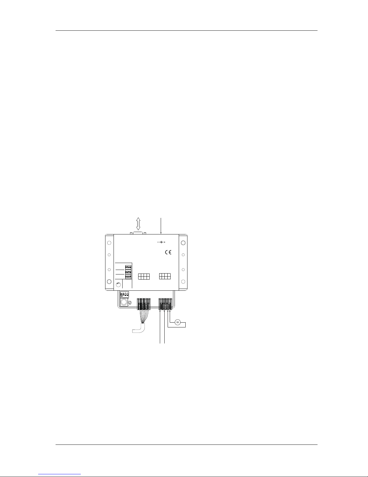
6 Mounting / Installation Operating manual mzr-2509 Ex/ mzr-2909 Ex / mzr-4609 Ex / mzr-7209 Ex
Last update: October 2016 Technische Änderungen ohne Vorankündigung vorbehalten. 43
Remarks:
− You may adjust speed of the micro annular gear pump without the need to
connect it to the serial interface.
− In case error occurs for example due to motor overload - the green status
LED on the Terminal Box S-G05 will turn red.
6.9.2 Startup with external 0-10 V signal
7. Connect the drive with the eight colored wires to the terminal box S-G05.
The colors of the corresponding wire connections are described in the
table 26.
8. Bring the potentiometer knob to the null position by turning it clockwise to
the limit stop.
9. Put the DIP-switch to »0…10 V« position.
10. Connect an external 0-10 V voltage supply to the terminal clamps
»AnalogIn« and »GND« to the S-G05. (see figure 13)
ON
1 2 3 4
ON
1 2 3 4
ON
1 2 3 4
0(4)...20 mA
0...10 V
Poti
Mode
Speed
Status
Ready: green
Fault: red
9
Dig. Input
TxD 16 15 RxD
1
3 An alog GND
F
ault Out 14
Anal og In. 12
2
4 VDC 10
1
1 GND
Termi n al Bo x S - G 05
HNP M ikrosy stem e Gm bH
RS-232 Pow er In
24 VDC
0
1
24 VDC / 4A
D
ig. Input 8
7
Fault5 Analog In.
G
ND 6
n.c. 4
G
ND 2
3 10 V out
ON
1 2 3 4
ON
1 2 3 4
ON
1 2 3 4
0(4)...20 mA
0...10 V
Poti
Mode
Speed
Status
Ready: green
Fault: red
D
ig. Input
16 RxD
A
nalog GND
14121
0
G
ND
Termi n al Bo x S - G 05
HNP M ikrosy stem e Gm bH
RS-232 Power In
24 VDC
2
4 VDC / 4A
F
aultAnalog In.
10 V out
TxD
F
ault Out
Analog In.
2
4 VDC
15
131
1
91753
D
ig. Input
G
ND
n.c.
G
ND
286
4
0
mzr-pumpJ2power / s ignal
J1
+ –
–
+
2165
serial
interface
of P C
alternative
power supply
24 V DC
mot or c able
st andard s ignal
0 -10 V
exter nal v oltage
24 V DC
figure 22 Startup with an external 0-10 V voltage signal
11. Provide for a steady liquid supply to the pump in order to avoid dry
operation of the device.
12. Connect the 24 VDC voltage supply to the terminal or to the DIN
connector.

6 Mounting / Installation Operation manual mzr-2509 Ex/ mzr-2909 Ex / mzr-4609 Ex / mzr-7209 Ex
44 Technische Änderungen ohne Vorankündigung vorbehalten Last update: October 2016
Make sure that the polarity of the supplied direct current is correct, otherwise
electronics will be damaged.
The input circuit at the analog input is layed out as a differential amplifier. If
the analog input is “open” there is already a voltage of 2 V. That means in
this case that the motor would be turning at a speed of about 2000 rpm. In
order to set 0 rpm the input must be connected over a low ohm resistor to
the analog ground (AGND) or connected to the AGND-voltage level.
13. The micro annular gear pump may now be put into operation by increasing
the external voltage signal. A voltage signal of 0 V corresponds to 0 rpm
and 10 V to the maximal programmed speed (see chapter 1.7).
Remarks:
− You may adjust speed of the micro annular gear pump without the need to
connect it to the serial interface.
− In case error occurs for example due to the motor overload - the green status
LED on the terminal Box S-G05 will turn red.
6.9.3 Startup with an external 0(4)-20 mA current signal
The conversion is done internally without electrical isolation. A potential
separation is possible only with a external transformer module.
14. Connect the drive with the eight colored wires to the terminal box S-G05.
The colors of the corresponding wire connections are described in the
table 26.
15. Bring the potentiometer knob to the zero position by turning it clockwise to
the limit stop.
16. Put the DIP-switch to »0(4)…20 mA« position.
17. Connect the external current source to the screw clamps »AnalogIn« and
»GND« to the S-G05. (see figure 14).

6 Mounting / Installation Operating manual mzr-2509 Ex/ mzr-2909 Ex / mzr-4609 Ex / mzr-7209 Ex
Last update: October 2016 Technische Änderungen ohne Vorankündigung vorbehalten. 45
ON
1 2 3 4
ON
1 2 3 4
ON
1 2 3 4
0(4)...20 mA
0...10 V
Poti
Mode
Speed
Status
Ready: green
Fault: red
9 Dig . Input
TxD 16 15 RxD
13 Analog GNDFault Out 14
Anal og In. 12
24 VDC 10
1
1 GND
Termi n al Bo x S - G 05
HNP M ikrosy stem e Gm bH
RS-232 Pow er In
24 VDC
0
1
24 VDC / 4A
D
ig. Input 8
7
Fault5 An alog In.
G
ND 6
n.c. 4
G
ND 2
3 10 V out
ON
1 2 3 4
ON
1 2 3 4
ON
1 2 3 4
0(4)...20 mA
0...10 V
Poti
Mode
Speed Status
Ready: green
Fault: red
Dig. Input
16 RxD
Analog GND14
12
10
GND
Termi n al Bo x S - G 05
HNP M ikrosy stem e Gm bH
RS-232 Power In
24 VDC
24 VDC / 4A
Fault
Analog In.
10 V out
TxD
Fault Out
Anal og In.
24 VDC
15131
1
91753
D
ig. Input
G
ND
n.c.
G
ND
286
4
0
mzr-pumpJ2power / s ignal
J1
+ –
–
+
2165
serial
interface
of P C
alternative
power supply
24 V DC
mot or c able
st andard s ignal
0 (4)- 20 mA
exter nal v oltage
24 V DC
figure 23 Operation via an external 0 (4)-20 mA voltage
18. Provide for a sufficient liquid supply to the pump in order to avoid dry
operation of the device.
19. Connect the 24 VDC voltage supply to the screw clamp terminal or to the
DIN connector.
Make sure that the polarity of the supplied direct current is correct, otherwise
electronics may be damaged.
20. The micro annular gear pump may now be put into operation by
increasing the external current signal. 0 mA corresponds to 0 rpm and
20 mA to the maximal programmed speed (see chapter 1.7).
Remarks:
− For operation with the signal 4…20 mA an offset of about 2.1 V should be
set by entering the command MAV2170. In order to set the nominal values
the micro annular gear pump must be put into operation via the RS-232
interface and start with the » Motion Manager « software. Save the
command in the EEPROM with the command EEPSAV (see chapter 8).
− Speed of the micro annular gear pump may be set by sending an external
voltage signal without the need to connect the pump to the serial interface.
− In case error occurs for example due to a motor overload - the green status
LED on the Terminal Box S-G05 will extinguish and a red one will light up.

6 Mounting / Installation Operation manual mzr-2509 Ex/ mzr-2909 Ex / mzr-4609 Ex / mzr-7209 Ex
46 Technische Änderungen ohne Vorankündigung vorbehalten Last update: October 2016
6.9.4 Startup with external potentiometer
21. Connect the drive with the eight colored wires to the terminal box S-G05.
The colors of the corresponding wire connections are described in the
table 26.
22. Bring the internal potentiometer knob to the null position by turning it
clockwise to the limit stop.
23. Put the DIP-switch to »0…10 V« position.
24. Connect an external 0-10 V voltage supply to the terminal clamps
»AnalogIn«, »10 V« and »GND« to the S-G05.(see figure 13)
ON
1 2 3 4
ON
1 2 3 4
ON
1 2 3 4
0(4)...20 mA
0...10 V
Poti
Mode
Speed Status
Ready: green
Fault: red
9 Dig. Input
TxD 16 15 RxD
13 Analog GNDFault Out 14
A nalog In. 12
24 VDC 10
11 GND
Termi n al Bo x S - G 05
HNP M ikrosy stem e Gm bH
RS-232 Pow er In
24 VDC
0
1
24 VDC / 4A
Dig. Input 8 7 Fault
5 Ana log In.GND 6
n.c. 4
G
ND 2
3 10 V out
ON
1 2 3 4
ON
1 2 3 4
ON
1 2 3 4
0(4)...20 mA
0...10 V
Poti
Mode
Speed Status
Ready: green
Fault: red
Dig. Input
16 RxD
Analog GND14
12
10
GND
Termi n al Bo x S - G 05
HNP M ikrosy stem e Gm bH
RS-232 Power In
24 VDC
2
4 VDC / 4A
Fault
Analog In.
10 V out
TxD
Fault Out
A nalog In.
24 VDC
151311
91753
D
ig. Input
GND
n.c.
G
ND
286
4
0
mzr-pumpJ2power / s ignal
J1
10 V
Potentiometer
exter nal
GND
Analog IN
– +
21653
mot or c able
exter nal v oltage
24 V DC
serial
interface
of P C
alternative
power supply
24 V DC
figure 24 Startup with an external potentiometer
25. Provide for a steady liquid supply to the pump in order to avoid dry
operation of the device.
26. Connect the 24 VDC voltage supply to the terminal or to the DIN
connector.
Make sure that the polarity of the supplied direct current is correct, otherwise
electronics will be damaged.

6 Mounting / Installation Operating manual mzr-2509 Ex/ mzr-2909 Ex / mzr-4609 Ex / mzr-7209 Ex
Last update: October 2016 Technische Änderungen ohne Vorankündigung vorbehalten. 47
The input circuit at the analog input is layed out as a differential amplifier. If
the analog input is “open” there is already a voltage of 2 V. That means in
this case that the motor would be turning at a speed of about 2000 rpm. In
order to set 0 rpm the input must be connected over a low ohm resistor to
the analog ground (AGND) or connected to the AGND-voltage level.
27. The micro annular gear pump may now be put into operation by increasing
the external voltage signal. A voltage signal of 0 V corresponds to 0 rpm
and 10 V to the maximal programmed speed (see chapter 1.7).
Remarks:
− You may adjust speed of the micro annular gear pump without the need to
connect it to the serial interface.
− In case error occurs for example due to the motor overload - the green status
LED on the terminal Box S-G05 will turn red.
6.9.5 Startup with the RS-232 interface
28. Connect the drive with the eight colored wires to the S-G05. The colors of
the corresponding wire connections are in the table 26.
29. In order to prevent uncontrolled startup of the pump, bring the
potentiometer knob to the null position by turning it clockwise to the limit
stop.
30. Put the DIP-switch to »Poti« position.
31. Connect the RS-232 interface of the Terminal Box S-G05 with a free serial
interface of a PC. Use for that the delivered 9-pole null-modem cable.
32. Now install the delivered software as described in the chapter 8.
33. Connect the 24 VDC voltage supply to the terminal or to the DIN
connector.
34. Provide for a steady liquid supply to the pump in order to avoid dry
operation of the device.
35. The micro annular gear pump may now be put into operation with the
available software (operating mode RS-232 see chapter 8).
Remarks:
− In case error occurs for example due to the motor overload - the green error
status LED on the Terminal Box S-G05 will turn red.

6 Mounting / Installation Operation manual mzr-2509 Ex/ mzr-2909 Ex / mzr-4609 Ex / mzr-7209 Ex
48 Technische Änderungen ohne Vorankündigung vorbehalten Last update: October 2016
6.10 Installation of the software »Motion Manager«
The program »Motion Manager« provides easy operation and configuration of
the motor together with an online graphic performance analysis tool. For
installation a PC with Windows XP
®
or Windows 7® is required.
Install the software »Motion Manager« which is included in the delivery CD.
After successful installation start the program »Motion Manager« in the file
»Faulhaber Motoren« via Windows
®
start menu.
If the diskettes of the »Motion Manager« are not delivered, because the
software »mzr-pump controller« was included instead, you can download the
software from the website http://www.hnp-mikrosysteme.de
. The latest version
can be downloaded in English or German under Downloads.
To program a micro annular gear pump motor and controller have to be put
into operation. Both units have to be connected with the zero-modem cable.

7 Start up / Shut down Operating manual mzr-2509 Ex/ mzr-2909 Ex / mzr-4609 Ex / mzr-7209 Ex
Last update: October 2016 Technische Änderungen ohne Vorankündigung vorbehalten. 49
7 Start up / Shut down
7.1 Prepare for start up
After the liquid supply system had been completed, please check once again
the operating conditions of the micro annular gear pump as according to the
following points:
− Are the inlet and outlet tubes correctly connected?
− Is the entire liquid supply system clean - that means free of particles, foreign
bodies, pollution or swarf?
− Has a filter been installed on the suction side?
− Has a sufficient amount of the right liquid been supplied?
− The pump does not run the risk of a dry operation?
− The entire liquid supply system has been checked for leakage?
− Is it possible to stop the pump by an emergency switch if an unexpected
malfunction occurs at the startup?
7.2 First start of a mzr-pump
Switch on power supply. Now the micro annular gear pump can be taken into
service by turning at the potentiometer or with help of the pump software (see
section 10).
Start the filling in of the pump at low or middle speed (1000 - 3000 rpm).
Warning
Avoid dry operation of the pump. The pump should be filled in before it is put
to operation.
If the pump is used in hazardous areas, it must not run dry. The pump and all
pipes must be primed and filled with liquid before starting.
7.3 Re-start after dry run
After a short dry run (it is assumed that the pump is not yet damaged), you
must ensure that the pump has cooled down to a temperature below its
maximally allowed surface temperature. The pump and the pipes must be
completely primed and filled.
Re-starting is prohibited after a longer dry run. The pump must be dismounted
to check for damage and any damaged parts replaced. The pump may only be
operated again after complete priming and filling and the restoration of the
earth.

7 Start up / Shut down Operation manual mzr-2509 Ex/ mzr-2909 Ex / mzr-4609 Ex / mzr-7209 Ex
50 Technische Änderungen ohne Vorankündigung vorbehalten Last update: October 2016
7.4 Operation of the micro annular gear pumps in different temperature ranges
Warning
Micro annular gear pumps are highly precise manufactured devices. No
contamination may reach the inside of the pump since this can damage the
pump. Make sure therefore, that all of the wetted parts are kept absolutely
free of dirt, dust or chips since this can affect the function of the pump.
Flow monitoring is also required for operation in hazardous areas to securely
prevent dry running. If the flow stops, the pump must be stopped
immediately.
During operation in hazardous areas, particular attention must be paid to the
heat input in the liquid as well as to the increase of the pump’s surface
temperature. To avoid temperatures above a critical surface temperature one
of the following two measures has to be implemented (see 7.5). If the
specified top temperature is exceeded, the pump must stop immediately. For
the monitoring the compliance with standard EN 13463-6 has to be respected.
Remove dust deposits regularly from the pump’s surface, drive and connection
pipes so as to prevent the formation of ignition sources. The cleaning interval
must be determined by the level of dust precipitation by the operator.
The fluid connections mounted to the pump have to be checked immediately
after putting into service and following to this in a six month cycle on tightness
and leakage.
Monitor the operating sound of the pump. If grinding noise occurs, switch off
the pump immediately. Check the pump for wear optically. Friction between
metallic parts can lead to overheating or formation of sparks.
If the pump is used in hazardous areas, a flow sensor must be installed directly
downstream of the pump. The flow sensor must not create a noticeable back
pressure in case of damage. If the delivery rate of the pump falls to 20% of
the theoretical flow rate, the pump must be stopped immediately.
For operation of the micro annular gear pumps in surroundings with Ex-zone
request of temperature range T1-3 and T4 no additional temperature measure
is necessary for monitoring.
For operation of the micro annular gear pump in surroundings with Ex-zone
request of temperature range T5 and T6 additional temperature monitoring is
necessary.

7 Start up / Shut down Operating manual mzr-2509 Ex/ mzr-2909 Ex / mzr-4609 Ex / mzr-7209 Ex
Last update: October 2016 Technische Änderungen ohne Vorankündigung vorbehalten. 51
7.5 Monitoring of operation in the temperature range T5, T6
Monitoring of surface temperature
Temperature range T5 T6
Max. surface temperature 60°C 45°C
Table 21 Max. surface temperature
Monitoring liquid temperature on pressure side
Temperature range T5 T6
Max. liquid temperature
80°C
70°C
Table 22 Maximum liquid temperature
7.6 Flushing procedure after use
After each service the micro annular gear pump should be carefully flushed
with a non-corrosive, filtered and particle-free flushing liquid (see table 21 and
table 22). During flushing procedure the pump should operate at a speed of
about 3000 rpm and if possible against a low pressure (that can be obtained by
using a restrictor, a capillary or similar). The flushing liquid must be compatible
with the delivered liquid and suitable for solving the remaining liquid rests.
Depending on the application for example water, or isopropanol may be used.
If you have doubts whether a particular liquid is suitable for this function or
not, please ask the manufacturer of the liquid or HNP Mikrosysteme.

7 Start up / Shut down Operation manual mzr-2509 Ex/ mzr-2909 Ex / mzr-4609 Ex / mzr-7209 Ex
52 Technische Änderungen ohne Vorankündigung vorbehalten Last update: October 2016
Flush the pump
Selection of flushing
liquid (FL)
Drain the pump
Right
flushing
liquid
Is the
pump
resistant?
nonoyes
yes
Flushing cycle
End of flushing
cycle
figure 25 Diagram of the flushing procedure
Warning
Liquids that remain in the pump may crystallize, coagulate or lead to corrosion
and as a consequence impair the work of the micro annular gear pump.
Warning
Please make sure that the pump components and particularly O-rings and
sealing are resistant to the employed flushing liquid. (see table 22).
Warning
The flushing liquid (solvent) and the recommended duration of the flushing
procedure depend on the delivered liquid (see table 22). The indicated flushing
liquids are simple recommendations and should therefore be checked by the
user as to their compatibility and suitability.
!
Regulations concerning use of substances dangerous to health should be
followed!
see table 22 (Resistance of the sealing material)
see table 21 (Selection of the flushing liquid)
see table 21 (Selection of the flushing liquid)

7 Start up / Shut down Operating manual mzr-2509 Ex/ mzr-2909 Ex / mzr-4609 Ex / mzr-7209 Ex
Last update: October 2016 Technische Änderungen ohne Vorankündigung vorbehalten. 53
Nature of the delivered liquid
Flushing time [min]
Suitable flushing liquid
1 Oils, fats, plastifierss 15-20
isopropanol, ethanol, acetone,
benzine/petroleum ether
2 Solvents (polar + nonpolar) 5-10 isopropanol, ethanol
3 Other organic liquids 10-15 isopropanol , ethanol
4 Refrigerating and cooling agents 15-20 isopropanol, ethanol
5
Neutral water/y solutions
20-25
isopropanol, ethanol
6 Basic solutions 25-30 DI-water (deionized water)
7 Organic acids 30-40 isopropanol, ethanol
8 Weak mineral acids 25-30 DI- water
9 Strong mineral acids 35-45 DI- water
10 Strong oxidizing liquids 35-45 DI- water
11 Paints, varnishes, adhesives 50-60
not specified - for further information
please contact HNP Mikrosysteme.
table 23 Selection of the flushing liquid (solvent) and the duration of the flushing procedure depending on the
delivered liquid.
Warning
Please make sure that the pump components and particularly O-rings and
sealing are resistant to the employed flushing liquid (see table 22).
Shaft sealing O-ring material
Flushing liquid
PTFE (Teflon®),
graphite-
reinforced
UHMWPE
FKM
(Viton®)
EPDM FFKM
acetone 0 0 3 0 0
benzene 0 3 1 3 0
benzyl alcohol 0 - 0 2 0
butanol 0 - 1 0 0
dimethyl sulfoxide (DMSO) 0 0 3 0 0
ethanol 0 0 0 0 0
isopropanol 0 0 0 0
0
methanol 0 0 2 0 0
methylethylketone (MEK) 0 0 3 1 0
styrene 0 - 1 3
1
toluene 0 1 2 3 0
water 0 0 0 0 0
xylene 0 1 2 3
0
benzine/petroleum ether 0 0 0 3 0
oil / fine mechanics oil 0 0 0 3 0
Legend: 0 ... good suitability 1 ... suitability 2 ... conditional suitability 3 ... labile - ... not specified
table 24 Resistance of the sealing materials depending on the flushing liquid (solvent)

7 Start up / Shut down Operation manual mzr-2509 Ex/ mzr-2909 Ex / mzr-4609 Ex / mzr-7209 Ex
54 Technische Änderungen ohne Vorankündigung vorbehalten Last update: October 2016
7.7 Shutdown of the micro annular gear pump
Ensure that no hazardous atmosphere is present.
In order to shut down a mzr-pump the following steps should be followed:
− Flush the pump with a filtered and particle-free flushing liquid (solvent) as
described in the chapter 7.6.
− After the flushing procedure decrease speed of the pump to 0 rpm
− Fill the pump with a suitable conservation liquid (see chapter 7.7.1)
− Remove the pump from the system (see chapter 7.7.2)
By proceeding as shown in the diagram (see figure 21) you may prepare the
pump for a longer standstill.

7 Start up / Shut down Operating manual mzr-2509 Ex/ mzr-2909 Ex / mzr-4609 Ex / mzr-7209 Ex
Last update: October 2016 Technische Änderungen ohne Vorankündigung vorbehalten. 55
Legend
FL = flushing liquid
CL = conservation liquid
End of test/operation
Drain the pump
Pump
requires
flushing?
Flushing cycle
Is the
pump
clean?
Selection of
conservation liquid
(CL)
Delivery of
solvents
manipulated
liquid =
conservation
liquid
Flush the pump
Selection of flushing
liquid (FL)
Drain the pump
Right
flushing
liquid
Is the
pump
resistant?
Selection of conservation
liquid (CL)
CL
adequate
Is the CL
compatible
with pump
Is the CL
compatible
with the
last FL ?
Nature of
the CL
Let the gas through
the pump
Fill in CL
Desinstall the
pump
Close the liquid
ports
End of conservation
procedure
New operation after
the conservation
procedure
liquid
yes
no
no
no
no
no
no
no
yes
yes
yes
yes
yes
yes
gaseous
no
yes
Flushing cycle
End of flushing
cycle
End of CL
selection
figure 26 Diagram of the shutdown procedure
see table 21
see table 22
see table 23
see table 22

7 Start up / Shut down Operation manual mzr-2509 Ex/ mzr-2909 Ex / mzr-4609 Ex / mzr-7209 Ex
56 Technische Änderungen ohne Vorankündigung vorbehalten Last update: October 2016
7.7.1 Conservation
If the micro annular gear pump operates at irregular intervals or for other
reasons should be put out of operation for a longer period, it should, after
service and flushing procedure (see chapter 7.6), be filled in with a suitable
conservation liquid.
The conservation liquid may be selected from the table 23 depending on the
duration of the standstill and the resistance of the pump to the manipulated
liquid. The indicated conservation liquids are simple recommendations and
should therefore be checked by the user as to their compatibility and suitability.
The figure 21 presents a diagram of conservation agent selection.
Remark: This diagram is repeated as a part of the figure 20 (shutdown
procedure of the micro annular gear pump).
After the cleansing procedure the pump should be filled with a suitable
conservation agent. You will find a choice of possible conservation agents in
the table 23.
Selection of conservation
liquid (CL)
CL
adequate
Is the CL
compatible
with pump
Is the CL
compatible
with the
last FL ?
yes
no
no
no
yes
yes
End of CL
selection
figure 27 Diagram - selection of conservation liquid (CL)
see table 22 (Resistance of the sealing material)
see table 23 (Selection of the conservation agent)

7 Start up / Shut down Operating manual mzr-2509 Ex/ mzr-2909 Ex / mzr-4609 Ex / mzr-7209 Ex
Last update: October 2016 Technische Änderungen ohne Vorankündigung vorbehalten. 57
Liquids
Solubility in
water
Compatibility
with the
delivered liquid
Duration of
storage Breakaway
torque Toxicology Viscosity Descri
ption
isopropanol + + o o o +
solvent for organic compounds, cosmetics, essential oils
waxes, and esters, antifreezers, antiseptic agents
acetone + + o o o +
solvent for a number of organic compounds, unlimited
solubility in water, dissolves natural and synthetic resins, fats,
oils and commonly used plastifiers
ethanol + + o o o + solvent for organic compounds, fats, oils and resins
DI-water + + - - + + solvent for many organic and mineral liquids
fine mechanics
oil
- - + + + +
cleansing and protective action (dissolves fats, tar, rubber or
adhesive substances, protects against corrosion).
hydraulic oil - - + + + -
lubricating and preserving properties (Warning: may resinate
or deteriorate with time)
nitrogen - + + + o + is not a solvent, may leave deposits after drying out
air /
compressed air
+ + + + + is not a solvent, may leave deposits after drying out
Legend: + ... good/suitable o ... satisfactory; - ... bad/inadequate
table 25 Selection of the conservation agent
In order to prevent dust particles and foreign bodies from penetrating into the
pump or the conservation agent from leaking out, please secure the liquid
input and output openings with the delivered protective plugs or screws.
Warning
Water or DI-water should not be used as conservative liquids. They germinate
already after a few days and build a biofilm which can later block the pump.
7.7.2 Dismantling of the system
− Put the drive out of operation by turning down speed to 0 rpm and by
switching off the voltage supply. Make sure that the procedure described in
the chapter 7.6 has been completed.
− Now that the pump has been stopped you may remove it from the system.
− Protect the inlet and outlet openings of the pump with adapted protective
plugs or screws.

7 Start up / Shut down Operation manual mzr-2509 Ex/ mzr-2909 Ex / mzr-4609 Ex / mzr-7209 Ex
58 Technische Änderungen ohne Vorankündigung vorbehalten Last update: October 2016
7.8 Trouble shooting
If the pump stops operating abruptly or has difficulties with starting operation,
please undertake the following steps:
Try to liberate the micro annular gear pump:
− by turning the potentiometer knob back and forth or by connecting an
analog voltage
− via the control software
− by pressing with a syringe a suitable flushing liquid (see table 21 and
table 22) through the micro annular gear pump
− by changing the operating direction of the pump.
If these measures turn out to be ineffective, please contact the service staff of
HNP Mikrosysteme (see chapter 15) and send the pump back to the
manufacturer for inspection.
Warning
You should under no condition try to disassemble the pump by yourself. This
may cause damage to the pump components and consequently annul your
warranty claims.
7.9 Return of the micro annular gear pump to the manufacturer
For the return of a micro annular gear pump and components that have already
been employed, please follow the instructions:
− drain any remaining rests of the delivered liquid from the pump
− flush the pump with an adapted solvent
− remove the filter elements from integrated or loosely delivered filters
− protect all openings against dust with the delivered protective plugs or
screws
− return the pump in its original packing
The service personnel which carries out the repair should be informed about
the condition of the already used micro annular gear pump. This is done by
means of the "Declaration of media in contact with the micro annular gear
pump and its components" (see chapter 16). This form may also be
downloaded from the web site www.hnp-mikrosysteme.de/download.
!
The "Declaration of liquids in contact with the micro annular gear pump and
its components" must imperatively be filled in. The nature of liquid which
entered into contact with the micro annular gear pump and its components
must be specified.
In case of non-compliance, the sender will be liable for any resulting injure to
persons or any object damage.

8 Maintenance and service Operating manual mzr-2509 Ex/ mzr-2909 Ex / mzr-4609 Ex / mzr-7209 Ex
Last update: October 2016 Technische Änderungen ohne Vorankündigung vorbehalten. 59
8 Maintenance and service
8.1 Micro annular gear pumps
The first maintenance of the micro annular gear pumps has to take place after
4000 hours or after 6 month latest. If wear is low at the first inspection further
maintenance intervals at the same operation conditions can be extended to
6000 hours or to a service interval of 12 month latest.
If there is increased wear at the first inspection the maintenance intervals have
to be adapted according to the wear situation.
In case of maintenance and service please send the micro annular gear pump to
your distributor or HNP Mikrosysteme directly. The address you may find on the
front page of the manual or in section 15.
The micro annular gear pumps is sealed. It is prohibited to open or disassemble
the pump. The warranty will expire immediately in such a case.
HNP Mikrosysteme cannot give any warranty for replacing in case of damages
to the pump which are related to faulty operation.
8.2 Metal bellow-type coupling
Maintenance of the standard metal bellow-type coupling is not necessary
according to the enclosed manufacturer’s data when assembled by
HNP Mikrosysteme.
Within the maintenance intervals of the pump the screw tightenining torque
must be checked after 6000 hours. If at the first inspection damage at the
metal bellow-type coupling is found the maintenance intervals have to be
adapted according to the operational data. This check must be part of the
maintenance intervals of the micro annular gear pump.
8.3 Ex-Motor
The explosion proof motor itself is maintenance free. According to the
manufacturer’s instruction the explosion proof motor has to be checked 1-2
times per year regarding cracks and damages. This check must be part of the
maintenance intervals of the micro annular gear pump.

9 Problems and their removal Operation manual mzr-2509 Ex/ mzr-2909 Ex / mzr-4609 Ex / mzr-7209 Ex
60 Technische Änderungen ohne Vorankündigung vorbehalten Last update: October 2016
9 Problems and their removal
Disturbance Cause Solution
1 The pump does not work.
No power supply
Check the power supply.
2 The pump does not pump the
liquid.
No liquid in the primary tank Fill the recipient/tank with liquid.
Presence of air or gas in the pump
The pump cannot run dry against the system
pressure. Fill in the pump at no pressure or at
reduced system pressure.
Malfunction of the liquid supply
components (such as in the delivery tube,
the needle or external non-return valve)
Check the components for possible
disturbances to be eliminated. Cleanse the
accessories where needed.
Failure of the electric installation
Check the electric installation for the correct
cable configuration, loose contacts, etc.
The pump did not receive the start signal
or start conditions are not fulfilled.
Check if the start condition have been fulfilled
start signals (software control, PLC, start signal)
and the programs.
Motor disturbance: the red error LED is on.
Check the failure condition of the motor
control with the Motion Manager software.
3 The pump does not start to
operate.
The pump does not take in the liquid.
The tubing on the induction side is too long or
has a too small internal diameter (a too low
NPSHA value).
The tubing or the fluid connection on the
induction (suction) side are not tight. Please
check the intake connection and the tubing.
Air bubbles in the fluid system
(tubes, valves, ...)
If the viscosity of the liquid is too high, apply
pressure on the suction side.
Check the pressure exerted on the primary
liquid tank.
An external non-return valve does not open.
Check the non-return valves.
Submit the non-return valve to a higher
pressure, so that the pump may fill in.
4 The motor turns, but the pump
does not operate.
No liquid in the pump Fill the pump with liquid.
Air bubbles in the liquid supply system
(tubing, valves, ...)
Fill the pump and the liquid supply system with
liquid.
The non-return valve does not open. Rinse the non-return valve.
Blocked delivery tubing or needle
Cleansing, flushing or exchange of the delivery
tubing or dosage needle
The coupling between the motor and the
pump is out of position.
Return the pump to the manufacturer.
The pump shaft is broken. Return the pump to the manufacturer.
5 The pump is filled with liquid, but
does not pump it.
Error indicator (the red status LED on the
terminal box is on and the motor control
has set the error output).
Check the motor error status with the Motion
Manager software (command GFS). Try to
liberate the pump by making it operate for 1 s
in a reverse direction with -1000 rpm.
Adapt the motor current to the control.
Contact the manufacturer of the pump.
Presence of particles in the delivered liquid
or blockage of the pump.
Check the motor error status with the Motion
Manager software.
Try to liberate the pump by making it operate
for 1 s in a reverse direction with -1000 rpm.
Return the pump to the manufacturer for
cleansing. Use a filter, flush the liquid delivery

9 Problems and their removal Operating manual mzr-2509 Ex/ mzr-2909 Ex / mzr-4609 Ex / mzr-7209 Ex
Last update: October 2016 Technische Änderungen ohne Vorankündigung vorbehalten. 61
Disturbance
Cause
Solution
system.
Flush the pump with a syringe.
The non-return valve does not open.
Rinse the non-return valve.
Blockage of the delivery tubing or the
needle.
Cleanse, flush or exchange the delivery tubing
or the needle.
Air bubbles in the liquid delivery system,
(tubing, valves)
Fill in the pump and the delivery system with
liquid.
6 Dosage volume does not
correspond to the set values.
Air bubbles in the liquid delivery system,
(tubing, valves ,...) and the pump
Vent the liquid delivery system and check for
untight fluid connections.
Pump shows cavitation.
Too long or too narrow intake tubing. Shorten
the intake tubing or change the position of the
pump.
Polluted or too small filter Change the filter to a new or bigger one.
The non-return valve does not open. Rinse the non-return valve.
7 Speed of the pump cannot be
adjusted.
Defective electric installation
Check the electric installation for correct cable
configuration and loose contacts.
Defective drive control Return the drive control to the manufacturer.
8 Liquid drops from the dosing
needle.
The non-return valve does not close. Rinse the non-return valve.
Too high pressure on the primary liquid
tank
Stop the delivery of compressed air on the
primary liquid tank.
The liquid tank is placed at a higher level
than the dosing needle.
Place the liquid tank at the same or slightly
lower level than the pump.
9 Liquid leaks from the fluidic seal.
The connection kit of the fluidic seal
module is untight.
Check the assembly, tighten the threaded
connections.
Pressure on the induction tank of the
fluidic seal liquid
Stop the delivery of compressed air on the
sealing liquid tank
Defective sealing - if necessary return the pump
to the manufacturer.
10 The dosage volume decreases with
time.
Polluted filter. Exchange the filter.
Deposits in the pump.
Flush the pump or return it to the
manufacturer for dismantling and cleaning.
The pump is worn after a long operating
period or after use with abrasive liquids.
New definition of the calibration factor of the
pump, by modifying the pump characteristics
graph necessary.
11 Leakage from the pump The sealing does not function correctly. Return the pump to the manufacturer.
12 Leakage from the coupling
assembly
Defective shaft seal
Return the pump to the manufacturer to
change the shaft sealing.
13 Leakage from the fluid connections Untight lock rings
Exchange or tighten the fluid connections,
exchange the fluid connection fittings.
14 Air bubbles on the delivery side
Loose fluid connections (particularly on the
induction side)
Check and tighten the fluid connections.
The shaft seal is untight or worn. Return the pump to the manufacturer.
15 Minimal leakage during standstill
No error, cause relative to the operating
principle
Employ a non-return valve.
Place the liquid tank at the same or slightly
lower level than the pump
16 Excess temperature The surface of the pump is hot. Clean the surface of the pump, rinse the pump
The pump operates with difficulty. The pump should be flushed.
Particles in the delivered liquid or deposits
in the pump
The operation of the pump should immediately
be stopped! Return the pump to the
manufacturer for cleansing.
Noise of beveling
The operation of the pump should immediately
be stopped! Return the pump to the
manufacturer for cleansing and repair.
The motor surface or the motor interior are
too hot.
High temperature indicator in the drive is on.
The motor has been shut down by the
thermistor. Return the pump to the

9 Problems and their removal Operation manual mzr-2509 Ex/ mzr-2909 Ex / mzr-4609 Ex / mzr-7209 Ex
62 Technische Änderungen ohne Vorankündigung vorbehalten Last update: October 2016
Disturbance
Cause
Solution
manufacturer.
17 The pump is noisy
Wearout of the pump or defective
components
Do not continue to operate the pump, return it
to the manufacturer for maintenance.
18 Lack of connection with the RS-232
interface
The pump is not connected. Check the power supply 24 VDC.
Check the connection of the interface and the
null-modem cable. Change the cable if
necessary.
The drive control does not respond.
Interrupt the voltage supply for about 10 s,
connect the voltage supply again. Automatic
start of the integrated drive control
19 Overcurrent Particles in the delivered liquid Rinse the pump.
The pump operates with difficulty.
Dosing needle is damaged. Needle should be
cleansed, flushed or exchanged.
Tubing on the delivery side, dosing needle or
non-return valve are blocked. Cleanse, flush or
exchange the components.
Deposits inside the pump.
Flush the pump. If necessary return the pump
to the manufacturer.
20 Undervoltage Voltage supply < 12 VDC Check the power supply 24 VDC.
21 Overvoltage Voltage supply > 28 VDC
Check the power supply 24 VDC. The drive
control may be damaged. Return the pump to
the manufacturer.
Table 26 Trouble shooting guide
If unknown faults appear or an uncertainty arises from appearing faults in the
working with the pump, immediately shut down the micro annular gear pump
at first!

10 Software »Motion Manager« Operating manual mzr-2509 Ex/ mzr-2909 Ex / mzr-4609 Ex / mzr-7209 Ex
Last update: October 2016 Technische Änderungen ohne Vorankündigung vorbehalten. 63
10 Software »Motion Manager«
For the programming of the micro annular gear pump the software » Motion
Manager « must be installed (see section 6.8). The connection from controller
to PC with the delivered zero modem cable has to be established and the micro
annular gear pump have been taken into service.
10.1 Command mode
With software »Motion Manager« commands can be entered and sent directly
to the motion controller to change the settings of the controller or execute
movements.
Figure 28 Program »Motion Manager« for direct control commands for the micro annular gear pump
The entry of command lines takes place in the field »Enter command:«. When
the command entry is completed this must be confirmed by pressing the
button »Send« to send. The commands can alternatively be written in capital or
small letters. Surplus blanks are ignored by the motion controller.

10 Software »Motion Manager« Operation manual mzr-2509 Ex/ mzr-2909 Ex / mzr-4609 Ex / mzr-7209 Ex
64 Technische Änderungen ohne Vorankündigung vorbehalten Last update: October 2016
Example for feeding
Command Description
SOR0
V1000
V0
V3000
SOR1
Operation mode »RS-232«, Source For Velocity - set velocity with
RS-232 command
Rotate with 1000 rpm
(equivalent flow for mzr-2509 Ex = 1,5 ml/min, mzr-2909 Ex =
3 ml/min; mzr-4609 Ex = 12 ml/min; mzr-7209 Ex = 48 ml/min)
Stop pump rotation (speed 0 rpm)
Rotate with 3000 rpm
(equivalent flow for mzr-2509 Ex = 4,5 ml/min, mzr-2909 Ex =
9 ml/min; mzr-4609 Ex = 36 ml/min; mzr-7209 Ex = 144 ml/min)
Operation mode »analogue input«, Source For Velocity - set
velocity with potentiometer setting on the connection panel
Example for dosage
Command Description
SOR0
LR10000
M
LR20000
M
SOR1
Operation mode »RS-232«, Source For Velocity - set velocity with
RS-232 command
Load relative position at 10000 to the pump
10000 = 5 revolution (equivalent quantity mzr-2509 Ex ≈ 7.5 µl
mzr-2909 Ex ≈ 15 µl; mzr-4609 Ex ≈ 60 µl, mzr-7209 Ex ≈ 240 µl)
(explanation: 2000 steps = 1 revolution)
Start positioning pump
Load relative position at 20000 to the pump
20000 = 10 revolution, (equivalent quantity mzr-2509 Ex ≈ 15 µl
mzr-2909 Ex ≈ 30 µl; mzr-4609 Ex ≈ 120 µl mzr-7209 Ex ≈
480 µl)
Start positioning pump
Operation mode »analogue input«, Source For Velocity - set
velocity with potentiometer setting on the connection panel
Regarding the four flank analysis of the encoder signal in the controller
S-HD-KL the counter of the position must be set four times the amount of
revolutions. To use the »Motion Manager« software please also refer to
the online help function of the program.

10 Software »Motion Manager« Operating manual mzr-2509 Ex/ mzr-2909 Ex / mzr-4609 Ex / mzr-7209 Ex
Last update: October 2016 Technische Änderungen ohne Vorankündigung vorbehalten. 65
10.2 Programming of motion controller
For dedicated applications (e.g. communication with process control, or dosage
parameters according to sensor input) the motion controller S-HD-KL can be
programmed with a simple program language. The program files consist of
ASCII-commands. The filenames can be saved with the extension »mcl«
(motion controller language). All motor settings can be set via the RS-232 port
(e.g. maximum velocity, acceleration, relative position in position control mode,
current parameter continuos and peak and the digital filter parameter for the
dynamic performance). All settings and files can be stored to the onboard
memory. Depending on the operation mode the motion controller therefore
can run stand-alone.
The delivery volume comprises a disk with sample mcl-files which can be
downloaded to the controller and stored permanently to the EEPROM.
10.3 Transfer of mcl-files to motor controller
mcl-files can be loaded over File – Open in the file-editor-screen.
Figure 29 Menu File – Open
The required mcl file may be selected and loaded from the file selection
window (see figure 24).

10 Software »Motion Manager« Operation manual mzr-2509 Ex/ mzr-2909 Ex / mzr-4609 Ex / mzr-7209 Ex
66 Technische Änderungen ohne Vorankündigung vorbehalten Last update: October 2016
figure 30 File selection window
Open the window Terminal – Transfer configuration files for file transfer to the
motion controller.
Figure 31 Transfer of mcl-file as Transfer configuration files

10 Software »Motion Manager« Operating manual mzr-2509 Ex/ mzr-2909 Ex / mzr-4609 Ex / mzr-7209 Ex
Last update: October 2016 Technische Änderungen ohne Vorankündigung vorbehalten. 67
When a window appears with the enquiry if the mcl files should be transferred
to the »Motion-Controller«, answer by clicking on the »Yes« button.
In order to save the configuration and the programmed operation files in the
EEPROM, please confirm the dialogue window with »OK« (see figure 26). With
this confirmation the program will be saved in the memory with a resident
status and will be available for future operation.
figure 32 Storage confirmation

10 Software »Motion Manager« Operation manual mzr-2509 Ex/ mzr-2909 Ex / mzr-4609 Ex / mzr-7209 Ex
68 Technische Änderungen ohne Vorankündigung vorbehalten Last update: October 2016
For saving of settings of the configuration or program sequence in the onboard
memory (EEPROM) answer the question »Should the EEPSAV command be
carried out and the transferred settings saved?« with »Yes«. At that time the
settings are written to the EEPROM. After switch on/off of the motion
controller settings and program is available.
The delivery volume comprises the standard program mzr-2509_S.mcl,
mzr-2909_S.mcl, mzr-4609_S.mcl, mzr-7209_S.mcl and the sample programs
switchdosage_2509_S.mcl, switchdosage_2909_S.mcl,
switchdosage_4609_S.mcl and switchdosage_7209_S.mcl for triggered dosage
with an external switch.
The standard program mzr-2509_S.mcl (see Listing 1) is saved at delivery state
of the micro annular gear pump mzr-2509 Ex.
Upon delivery the motion controller is configured with following parameter:
− Operation mode analogue input, Source for velocity via potentiometer
(Command SOR1)
− Enable driver (Command EN)
− Continuous mode (Command CONTMOD)
− Maximum velocity 4700 U/min (Command SP4700)
− Maximum peak current 800 mA (Command LPC800)
− Maximum continuous current 600 mA (Command LCC600)
− Acceleration 550 U/s² (Command AC550)
− Fault pin as error output (Command ERROUT)
− Asynchronous answer (Command ANSW1)
− Clear program memory with no programs
; File: mzr-2509_S.mcl
; Description: Standard mcl-file for micro annular gear pump mzr-2509Ex
; Speed is controlled by potentiometer of the connection panel
; Fault as error output program
; Hardware: Motion Controller S-HD-KL, Steuerung MCDC3006S, Schnittstelle RS-232
;
; Date: 2012-03-29
; Copyright © 2012, HNP Mikrosysteme GmbH, Parchim
;
; HNP Mikrosysteme Gm bH, Juri-Gagarin-Ring 4, 19370 Parchim
; Telefon +49(0)3871/451-301, Telefax +49(0)3871/451-333
; Email info@hnp-mikrosysteme.de, http://www.hnp-mikrosysteme.de
;
;-------------------------------------------------------------------------------------------------------------; Configuration Motor
;--------------------------------------------------------------------------------------------------------------
SOR1 ;Source For Velocity - Solldrehzahl über Potentiometer
CONTMOD ;Continuous Mode - Normalbetrieb
KN246 ;Load Speed Constant - Drehzahlkonstante laden [rpm/V]
RM1230 ;Load Motor Resistance - Motorwiderstand laden [mOhm]
APL0 ;Position Limits - Positionslimits deaktivieren
MOTTYP8 ;Motor Type - EC-Motor 3564K024B C
POHOSEQ0 ;Power On Homing Sequence - Keine Homing-Sequenze nach dem
Einschalten
ERROUT ;Error Output - Umschalten auf Fehlerausgangsmodus
HP7 ;Hard Pol ari t y - alle Eingänge steigende Flanke gülti g
HB0 ;Hard Blocking - Kein Hard-Blocking
HD0 ;Hard Direction - Für alle Endschalter Linkslauf sperren (falls Hard-Blocking
aktiv)

10 Software »Motion Manager« Operating manual mzr-2509 Ex/ mzr-2909 Ex / mzr-4609 Ex / mzr-7209 Ex
Last update: October 2016 Technische Änderungen ohne Vorankündigung vorbehalten. 69
HOSP100 ;Load Homing Speed - Homing-Speed auf Rechtslauf mit 100 rpm
SHA0 ;Set Home Armin g - deaktivieren
SHL0 ;Set Hard Limit - deaktivieren
SHN0 ;Set Hard Notify - deaktivieren
ADR ;Analog Direction Right - Positive Spannung für Rechtsdrehung
LPC800 ;Load Peak Current Limit - Spitzenstrom [mA] laden
LCC600 ;Load Contini us Current Limit - Dauerstrom [mA] laden
AC550 ;Load Command Acceleration - Beschleunigung laden [U/s²]
DEC550 ;Load Command Deceleration - Bremsverzögerung laden [U/s²]
I25 ;Load Velocity Integral Term - Drehzahlreglerintegralant ei l l aden
POR3 ;Load Velocity Proportional Term - Drehzahlreglerverst ärkung laden
PP162 ;Load Position P roport i onal Term - Ladereglerverstärk ung l aden
PD5 ;Load Posi tion D-Term - Lageregler D-Anteil laden
CI16 ;Load Current Intergral Term - Integralanteil für Stromregler laden
SP4700 ;Load maximum Speed - Maximaldrehzahl laden [rpm]
MV0 ; Minimum Velocity - Minimaldrehzahl laden [rpm]
MAV25 ;Minimum Analog Voltage - minimale Anlaufspannung in [mV]
LL600000000 ;Load Position Range Limits - obere Grenzpositionen laden
LL-600000000 ;Load Position Range Limits - Untere Grenzpositionen laden
LPN10 ;Load Puls Number - Impulszahl vorgeben
STW1 ;Load Step Width - Schrittweite an Motor senden
STN500 ;Load Step Number - Anzahl der Schritte pro Umdrehung laden
ENCRES2000 ;Load Encoder Resolution - Encoderauflösung Motor
DEV25 ; Load Deviation - größte zulässige Drehzahlabweichung laden
DCE200 ;Delayed Current Error - verzögerter Fehlerausgang [in 1/100 Sek.]
CORRIDOR10 ;Load Corridor - Fenster um die Zielposition laden
SIN1 ;Sinus Commutation
SETPLC ;Set PLC-Inputs - Eingangspegel auf PLC Kompatible 24 VDC
EN ;Enable Drive - Antrieb aktivieren
V0 ;S el ect Vel ocity Mode - Drehzahl [rpm] auf 0 setzen
DIPROG ;Disable Program - Ausführung des Programmes deaktivieren
COMPATIBLE0 ;Deactived Compatible Mode - Kompatibilität zu Vorgängermodellen
deaktivieren
SR1 ;Load Sam ple rat e - Reglerabtast rate [1 = 100µs]
NET0 ;Set Network Mode - Netzwerkbetrieb deaktiviert
ANSW1 ;Answer Mode- asynchronen Rückmeldungen über RS232 erlauben
;-------------------------------------------------------------------------------------------------------------; Programm
;--------------------------------------------------------------------------------------------------------------
PROGSEQ
;leeres Programm schreiben und speichern um eventuelle Programme zu
überschreiben
END
Listing 1 File mzr-2509 Ex.mcl
The standard program mzr-2909_S.mcl (see Listing 1) is saved at delivery state
of the micro annular gear pump mzr-2909 Ex.
Upon delivery the motion controller is configured with following parameter:
− Operation mode analogue input, Source for velocity via potentiometer
(Command SOR1)
− Enable driver (Command EN)
− Continuous mode (Command CONTMOD)
− Maximum velocity 4700 U/min (Command SP4700)
− Maximum peak current 800 mA (Command LPC800)
− Maximum continuous current 600 mA (Command LCC600)
− Acceleration 550 U/s² (Command AC550)
− Fault pin as error output (Command ERROUT)

10 Software »Motion Manager« Operation manual mzr-2509 Ex/ mzr-2909 Ex / mzr-4609 Ex / mzr-7209 Ex
70 Technische Änderungen ohne Vorankündigung vorbehalten Last update: October 2016
− Asynchronous answer (Command ANSW1)
− Clear program memory with no programs
; File: mzr-2909_S.mcl
; Description: Standard mcl-file for micro annular gear pump mzr-2909Ex
; Speed is controlled by potentiometer of the connection panel
; Fault as error output program
; Hardware: Motion Controller S -HD-KL, Steuerung MCDC3006S, Sc hnittstel l e RS-232
;
; Date: 2012-03-29
; Copyright © 2012, HNP Mikrosysteme GmbH, Parchim
;
; HNP Mikrosysteme Gm bH, Juri-Gagarin-Ring 4, 19370 Parchim
; Telefon +49(0)3871/451-301, Telefax +49(0)3871/451-333
; Email info@hnp-mikrosysteme.de, http://www.hnp-mikrosysteme.de
;
;-------------------------------------------------------------------------------------------------------------; Configuration Motor
;--------------------------------------------------------------------------------------------------------------
SOR1 ;Source For Velocity - Solldrehzahl über Potentiometer
CONTMOD ;Continuous Mode - Normalbetrieb
KN246 ;Load Speed Constant - Drehzahlkonstante laden [rpm/V]
RM1230 ;Load Motor Resistance - Motorwiderstand laden [mOhm]
APL0 ;Position Limits - Positionslimits deaktivieren
MOTTYP8 ; Motor T ype - EC-Motor 3564K024B C
POHOSEQ0 ;Power On Homing Sequence - Keine Homing-Sequenze nach dem
Einschalten
ERROUT ;Error Output - Umschalten auf Fehlerausgangsmodus
HP7 ;Hard Pol ari t y - alle Eingänge steigende Flanke gült ig
HB0 ;Hard Bl ocking - Kein Hard-Blocking
HD0 ;Hard Direction - Für alle Endschalter Linkslauf sperren (falls Hard-Blocking
aktiv)
HOSP100 ;Load Homing Speed - Homing-Speed auf Rechtslauf mit 100 rpm
SHA0 ;Set Home Armin g - deaktivieren
SHL0 ;Set Hard Limit - deaktivieren
SHN0 ;Set Hard Notify - deaktivieren
ADR ;Analog Direction Right - Positive Spannung für Rechtsdrehung
LPC800 ;Load Peak Current Limit - Spitzenstrom [mA] laden
LCC600 ;Load Contini us Current Limit - Dauerstrom [mA] laden
AC550 ;Load Command Acceleration - Beschleunigung laden [U/s²]
DEC550 ;Load Command Deceleration - Bremsverzögerung laden [U/s²]
I25 ;Load Velocity Integral Term - Drehzahlreglerintegralant ei l l aden
POR3 ;Load Velocity Proportional Term - Drehzahlreglerverstärkung laden
PP162 ;Load Position P roport i onal Term - Ladereglerverstärk ung l aden
PD5 ;Load Posi tion D-Term - Lageregler D-Anteil laden
CI16 ;Load Current Intergral Term - Integralanteil für Stromregler laden
SP4700 ;Load maximum Speed - Maximaldrehzahl laden [rpm]
MV0 ; Minimum Velocity - Minimaldrehzahl laden [rpm]
MAV25 ;Minimum Analog Voltage - minimale Anlaufspannung in [mV]
LL600000000 ;Load Position Range Limits - obere Grenzpositionen laden
LL-600000000 ;Load Position Range Limits - Untere Grenzpositionen laden
LPN10 ;Load Puls Number - Impulszahl vorgeben
STW1 ;Load Step Width - Schrittweite an Motor senden
STN500 ;Load Step Number - Anzahl der Schritte pro Umdrehung laden
ENCRES2000 ;Load Encoder Resolution - Encoderauflösung Motor
DEV25 ; Load Deviation - größte zulässige Drehzahlabweichung laden
DCE200 ;Delayed Current Error - verzögerter Fehlerausgang [in 1/100 Sek.]
CORRIDOR10 ;Load Corridor - Fenster um die Zielposition laden
SIN1 ;Sinus Commu tation
SETPLC ;Set PLC-Inputs - Eingangspegel auf PLC Kompatible 24 VDC
EN ;Enable Drive - Antrieb aktivieren
V0 ;S el ect Vel ocity Mode - Drehzahl [rpm] auf 0 setzen
DIPROG ;Disable Program - Ausführung des Programmes deaktivieren
COMPATIBLE0 ;Deactived Compatible Mode - Kompatibilität zu Vorgängermodellen
deaktivieren
SR1 ;Load Sam ple rat e - Reglerabtast rate [1 = 100µs]
NET0 ;Set Network Mode - Netzwerkbetrieb deaktiviert
ANSW1 ;Answer Mode- asynchronen Rückmeldungen über RS232 erlauben

10 Software »Motion Manager« Operating manual mzr-2509 Ex/ mzr-2909 Ex / mzr-4609 Ex / mzr-7209 Ex
Last update: October 2016 Technische Änderungen ohne Vorankündigung vorbehalten. 71
;-------------------------------------------------------------------------------------------------------------; Programm
;--------------------------------------------------------------------------------------------------------------
PROGSEQ
;leeres Programm schreiben und speichern um eventuelle Programme zu
überschreiben
END
Listing 2 File mzr-2909_S.mcl

10 Software »Motion Manager« Operation manual mzr-2509 Ex/ mzr-2909 Ex / mzr-4609 Ex / mzr-7209 Ex
72 Technische Änderungen ohne Vorankündigung vorbehalten Last update: October 2016
The standard program mzr-4609_S.mcl (see Listing 3) is saved at delivery state
of the micro annular gear pump mzr-4609 Ex.
Upon delivery the motion controller is configured with following parameter:
− Operation mode Analogue input, Source for velocity via potentiometer
(Command SOR1)
− Enable driver (Command EN)
− Continuous mode (Command CONTMOD)
− Maximum Velocity 4700 U/min (Command SP4700)
− Maximum peak current 900 mA (Command LPC900)
− Maximum continuous current 700 mA (Command LCC700)
− Acceleration 550 U/s² (Command AC550)
− Fault pin as error output (Command ERROUT)
− Asynchronous answer (Command ANSW1)
− Clear program memory with no programs
; File: mzr-4609_S.mcl
; Description: Standard mcl-file for micro annular gear pump mzr-4609Ex
; Speed is controlled by potentiometer of the connection panel
; Fault as error output program
; Hardware: Motion Controller S -HD-KL, Steuerung MCDC3006S, Sc hnittstel l e RS-232
;
; Date: 2012-03-29
; Copyright © 2012, HNP Mikrosysteme GmbH, Parchim
;
; HNP Mikrosysteme Gm bH, Juri-Gagarin-Ring 4, 19370 Parchim
; Telefon +49(0)3871/451-301, Telefax +49(0)3871/451-333
; Email info@hnp-mikrosysteme.de, http://www.hnp-mikrosysteme.de
;
;-------------------------------------------------------------------------------------------------------------; Configuration Motor
;--------------------------------------------------------------------------------------------------------------
SOR1 ;Source For Velocity - Solldrehzahl über Potentiometer
CONTMOD ;Continuous Mode - Normalbetrieb
KN246 ;Load Speed Constant - Drehzahlkonstante laden [rpm/V]
RM1230 ;Load Motor Resistance - Motorwiderstand laden [mOhm]
APL0 ;Position L i mits - Positionslimits deakti vieren
MOTTYP8 ; Motor T ype - EC-Motor 3564K024B C
POHOSEQ0 ;Power On Homing Sequence - Keine Homing-Sequenze nach dem
Einschalten
ERROUT ;Error Output - Umschalten auf Fehlerausgangsmodus
HP7 ;Hard Pol ari t y - alle Eingänge steigende Flanke gültig
HB0 ;Hard Bl ocking - Kein Hard-Blocking
HD0 ;Hard Direction - Für alle Endschalter Linkslauf sperren (falls Hard-Blocking
aktiv)
HOSP100 ;Load Homing Speed - Homing-Speed auf Rechtslauf mit 100 rpm
SHA0 ;Set H ome Arm ing - deaktivieren
SHL0 ;Set Hard Limit - deaktivieren
SHN0 ;Set Hard Notify - deaktivieren
ADR ;Analog Direction Right - Positive Spannung für Rechtsdrehung
LPC900 ;Load Peak Current Limit - Spitzenstrom [mA] laden
LCC700 ;Load Contini us Current Limit - Dauerstrom [mA] laden
AC550 ;Load Command Acceleration - Beschleunigung laden [U/s²]
DEC550 ;Load Command Deceleration - Bremsverzögerung laden [U/s²]
I25 ;Load Velocity Integral Term - Drehzahlreglerintegralant ei l l aden
POR3 ;Load Velocity Proportional Term - Drehzahlreglerverst ärkung laden
PP162 ;Load Position P roport i onal Term - Ladereglerverstärk ung l aden
PD5 ;Load Posi tion D-Term - Lageregler D-Anteil laden
CI16 ;Load Current Intergral Term - Integralanteil für Stromregler laden
SP4700 ;Load maximum Speed - Maximaldrehzahl laden [rpm]
MV0 ; Minimum Velocity - Minimaldrehzahl laden [rpm]
MAV25 ;Minimum Analog Voltage - minimale Anlaufspannung in [mV]
LL600000000 ;Load Position Range Limits - obere Grenzpositionen laden

10 Software »Motion Manager« Operating manual mzr-2509 Ex/ mzr-2909 Ex / mzr-4609 Ex / mzr-7209 Ex
Last update: October 2016 Technische Änderungen ohne Vorankündigung vorbehalten. 73
LL-600000000 ;Load Position Range Limits - Untere Grenzpositionen laden
LPN10 ;Load Puls Number - Impulszahl vorgeben
STW1 ;Load Step Width - Schrittweite an Motor senden
STN500 ;Load Step Number - Anzahl der Schritte pro Umdrehung laden
ENCRES2000 ;Load Encoder Resolution - Encoderauflösung Motor
DEV25 ; Load Deviation - größte zulässige Drehzahlabweichung laden
DCE200 ;Delayed Current Error - verzögerter Fehlerausgang [in 1/100 Sek.]
CORRIDOR10 ;Load Corridor - Fenster um die Zielposition laden
SIN1 ; S i nus Commut ation
SETPLC ;Set PLC-Inputs - Eingangspegel auf PLC Kompatible 24 VDC
EN ;Enable Drive - Antrieb aktivieren
V0 ;S el ect Vel ocity Mode - Drehzahl [rpm] auf 0 setzen
DIPROG ;Disable Program - Ausführung des Programmes deaktivieren
COMPATIBLE0 ;Deactived Compatible Mode - Kompatibilität zu Vorgängermodellen
deaktivieren
SR1 ;Load Sam ple rat e - Reglerabtast rate [1 = 100µs]
NET0 ;Set Network Mode - Netzwerkbetrieb deaktiviert
ANSW1 ;Answer Mode- asynchronen Rückmeldungen über RS232 erlauben
;-------------------------------------------------------------------------------------------------------------; Programm
;--------------------------------------------------------------------------------------------------------------
PROGSEQ
;leeres Programm schreiben und speichern um eventuelle Programme zu
überschreiben
END
Listing 3 File mzr-4609_S.mcl
The standard program mzr-7209_S.mcl (see Listing 4) is saved at delivery state
of the micro annular gear pump mzr-7209 Ex.
Upon delivery the motion controller is configured with following parameter:
− Operation state analogue input, Source for velocity over the potentiometer
(Command SOR1)
− Enable driver (Command EN)
− Continuous mode (Command CONTMOD)
− Maximum Velocity 4700 U/min (Command SP4700)
− Maximum peak current 2000 mA (Command LPC2000)
− Maximum continuous current 1800 mA (Command LCC1800)
− Acceleration 550 U/s² (Command AC550)
− Fault pin as error output (Command ERROUT)
− Asynchronous answer (Command ANSW1)
− Clear program memory with no programs
; File: mzr-7209_S.mcl
; Description: Standard mcl-file for micro annular gear pump mzr-7209Ex
; Speed is controlled by potentiometer of the connection panel
; Fault as error output program
; Hardware: Motion Controller S -HD-KL, Steuerung MCDC3006S, Schnittstell e RS-232
;
; Date: 2012-03-29
; Copyright © 2012, HNP Mikrosysteme GmbH, Parchim
;
; HNP Mikrosysteme Gm bH, Juri-Gagarin-Ring 4, 19370 Parchim
; Telefon +49(0)3871/451-301, Telefax +49(0)3871/451-333
; Email info@hnp-mikrosysteme.de, http://www.hnp-mikrosysteme.de
;

10 Software »Motion Manager« Operation manual mzr-2509 Ex/ mzr-2909 Ex / mzr-4609 Ex / mzr-7209 Ex
74 Technische Änderungen ohne Vorankündigung vorbehalten Last update: October 2016
;-------------------------------------------------------------------------------------------------------------; Configuration Motor
;--------------------------------------------------------------------------------------------------------------
SOR1 ;Source For Velocity - Solldrehzahl über Potentiometer
CONTMOD ;Continuous Mode - Normalbetrieb
KN246 ;Load Speed Constant - Drehzahlkonstante laden [rpm/V]
RM1230 ;Load Motor Resistance - Motorwiderstand laden [mOhm]
APL0 ;Position Limits - Positionslimits deaktivieren
MOTTYP8 ; Motor T ype - EC-Motor 3564K024B C
POHOSEQ0 ;Power On Homing Sequence - Keine Homing-Sequenze nach dem
Einschalten
ERROUT ;Error Output - Umschalten auf Fehlerausgangsmodus
HP7 ;Hard Pol ari t y - alle Eingänge steigende Flanke gülti g
HB0 ;Hard Bl ocking - Kein Hard-Blocking
HD0 ;Hard Direction - Für alle Endschalter Linkslauf sperren (falls Hard-Blocking
aktiv)
HOSP100 ;Load Homing Speed - Homing-Speed auf Rechtslauf mit 100 rpm
SHA0 ;Set Home Armin g - deaktivieren
SHL0 ;Set Hard Limit - deaktivieren
SHN0 ;Set Hard Notify - deaktivieren
ADR ;Analog Direction Right - Positive Spannung für Rechtsdrehung
LPC2000 ;Load Peak Current Limit - Spitzens trom [mA] laden
LCC1800 ;Load Continius Current Limit - Dauerstrom [mA] laden
AC550 ;Load Command Acceleration - Beschleunigung laden [U/s²]
DEC550 ;Load Command Deceleration - Bremsverzögerung laden [U/s²]
I25 ;Load Velocity Integral Term - Drehzahlreglerintegralant ei l l aden
POR3 ;Load Velocity Proportional Term - Drehzahlreglerverst ärkung laden
PP162 ;Load Position P roport i onal Term - Ladereglerverstärk ung l aden
PD5 ;Load Posi tion D-Term - Lageregler D-Anteil laden
CI16 ;Load Current Intergral Term - Integralanteil für Stromregler laden
SP4700 ;Load maximum Speed - Maximaldrehzahl laden [rpm]
MV0 ; Minimum Velocity - Minimaldrehzahl laden [rpm]
MAV25 ;Minimum Analog Voltage - minimale Anlaufspannung in [mV]
LL600000000 ;Load Position Range Limits - obere Grenzpositionen laden
LL-600000000 ;Load Position Range Limits - Untere Grenzpositionen laden
LPN10 ;Load Puls Number - Impulszahl vorgeben
STW1 ;Load Step Width - Schrittweite an Motor senden
STN500 ;Load Step Number - Anzahl der Schritte pro Umdrehung laden
ENCRES2000 ;Load Encoder Resolution - Encoderauflösung Motor
DEV25 ; Load Deviation - größte zulässige Drehzahlabweichung laden
DCE200 ;Delayed Current Error - verzögerter Fehlerausgang [in 1/100 Sek.]
CORRIDOR10 ;Load Corridor - Fenster um die Zielposition laden
SIN1 ;Sinus Commutation
SETPLC ;Set PLC-Inputs - Eingangspegel auf PLC Kompatible 24 VDC
EN ;Enable Drive - Antrieb aktivieren
V0 ;S el ect Vel ocity Mode - Drehzahl [rpm] auf 0 setzen
DIPROG ;Disable Program - Ausführung des Programmes deakti vi eren
COMPATIBLE0 ;Deactived Compatible Mode - Kompatibilität zu Vorgängermodellen
deaktivieren
SR1 ;Load Sam ple rat e - Reglerabtast rate [1 = 100µs]
NET0 ;Set Network Mode - Netzwerkbetrieb deaktiviert
ANSW1 ;Answer Mode- asynchronen Rückmeldungen über RS232 erlauben
;-------------------------------------------------------------------------------------------------------------; Programm
;--------------------------------------------------------------------------------------------------------------
PROGSEQ
;leeres Programm schreiben und speichern um eventuelle Programme zu
überschreiben
END
Listing 4 File mzr-7209_S.mcl

10 Software »Motion Manager« Operating manual mzr-2509 Ex/ mzr-2909 Ex / mzr-4609 Ex / mzr-7209 Ex
Last update: October 2016 Technische Änderungen ohne Vorankündigung vorbehalten. 75
The file switchdosage_mzr-2509_S.mcl (see Listing 5) is an example for dosage
with one micro annular gear pump mzr-2509 Ex.
Trigger start of the dosage with switch located between clamp »Fault« and
»GND« of the connection board. A closing switch or a floating switch of a PLC
can be used as trigger.
In the program the motion controller is programmed with following setting
parameters:
− Load relative Position of the pump 10 revolution (Command LR20000)
(20000 = 10 revolution => mzr-2509 Ex ≈ 15 µl)
− Start of dosage with switch (Command REFIN)
; File: switchdosage_2509_e3_S.mcl
; Description: Dosage triggered with switch for mzr-2509 Ex
; Start dosage with switch on digital input 3
; Fault as error output programmed
; Hardware: Motion Controller S-HD-KL with switch, Control l er MCDC3006S, Interface RS-232
;
; Date: 2012-03-29
; Copyright © 2012, HNP Mikrosysteme GmbH, Parchim
;
; HNP Mikrosysteme Gm bH, Juri-Gagarin-Ring 4, 19370 Parchim
; Telefon +49(0)3871/451-301, Telefax +49(0)3871/451-333
; Email: info@hnp-mikrosysteme.de, http://www.hnp-mikrosysteme.de
;
; ! ! ! Important ! ! !
; - Turn the potentiometer on the connection panel into zero position by
; turning clockwise to the right stop motion device
; - Then transfer this file with menu command 'Terminal - Transfer configuration file' to the
pump
; - Save the transferred settings into the EEPROM
;-------------------------------------------------------------------------------------------------------------; Program sequence
;-------------------------------------------------------------------------------------------------------------PROGSEQ ;Program start
A1 ;Label 1 (program st art)
HP4 ;Ris i ng edge active and logic level to High for input No. 3
A2 ;Label 2
JPT2 ;Cycle 2 Low-Pegel on Input 3
HP0 ;Fal l i ng edge active and logic level to Low for input No. 3
A3 ;Label 3
JPT3 ;Cycle 3 bis High-Pegel on Input 3
HO ;Set the actual position to 0
LR20000 ;Load relative target position (2000 = 1 rev.) <------- Please edit the target
position value !
NP ;Notify Position (wait aft er "M" until target positi on is reached)
M ;Move to target position
JMP1 ;Jump to the beginning
END
;--------------------------------------------------------------------------------------------------------------
; Configuration
;--------------------------------------------------------------------------------------------------------------
SOR0 ;Source For Velocity - Solldrehzahl über Schnittstelle RS-232
CONTMOD ;Continuous Mode - Normalbetrieb
KN246 ;Load Speed Constant - Drehzahlkonstante laden [rpm/V]
RM1230 ;Load Motor Resistance - Motorwiderstand laden [mOhm]
APL0 ;Position Limits - Positionslimits deaktivieren
MOTTYP8 ; Motor T ype - EC-Motor 3564K024B C

10 Software »Motion Manager« Operation manual mzr-2509 Ex/ mzr-2909 Ex / mzr-4609 Ex / mzr-7209 Ex
76 Technische Änderungen ohne Vorankündigung vorbehalten Last update: October 2016
POHOSEQ0 ;Power On Homing Sequence - Keine Homing-Sequenze nach dem
Einschalten
ERROUT ;Error Output - Umschalten auf Fehlerausgangsmodus
HP7 ;Hard P ol ari ty - alle Eingänge steigende Flanke gültig
HB0 ;Hard Bl ocking - Kein Hard-Blocking
HD0 ;Hard Direction - Für alle Endschalter Linkslauf sperren (falls Hard-Blocking
aktiv)
HOSP100 ;Load Homing Speed - Homing-Speed auf Rechtslauf mit 100 rpm
SHA0 ;Set Home Armin g - deaktivieren
SHL0 ;Set Hard Limit - deaktivieren
SHN0 ;Set Hard Notify - deaktivieren
ADR ;Analog Direction Right - Positive Spannung für Rechtsdrehung
LPC800 ;Load Peak Current Limit - Spitzenstrom [mA] laden
LCC600 ;Load Contini us Current Limit - Dauerstrom [mA] laden
AC550 ;Load Command Acceleration - Beschleunigung laden [U/s²]
DEC550 ;Load Command Deceleration - Bremsverzögerung laden [U/s²]
I25 ;Load Velocity Integral Term - Drehzahlreglerintegralant ei l l aden
POR2 ;Load Velocity Proportional Term - Drehzahlreglerverst ärkung laden
PP3 ;Load Position Proportional Term - Ladereglerverstärkung laden
PD20 ;Load Position D-Term - Lageregler D-Anteil laden
CI16 ;Load Current Intergral Term - Integralanteil für Stromregler laden
SP3000 ;Load maximum Speed - Maximaldrehzahl laden [rpm]
MV0 ; Minimum Velocity - Minimaldrehzahl laden [rpm]
MAV25 ;Minimum Analog Voltage - minimale Anlaufspannung in [mV]
LL600000000 ;Load Position Range Limits - obere Grenzpositionen laden
LL-600000000 ;Load Position Range Limits - Untere Grenzpositionen laden
LPN10 ;Load Puls Number - Impulszahl vorgeben
STW1 ;Load Step Width - Schrittweite an Motor senden
STN500 ;Load Step Number - Anzahl der Schritte pro Umdrehung laden
ENCRES2000 ;Load Encoder Resolution - Encoderauflösung Motor
DEV25 ; Load Deviation - größte zulässige Drehzahlabweichung laden
DCE200 ;Delayed Current Error - verzögerter Fehlerausgang [in 1/100 Sek.]
CORRIDOR100 ;Load Corridor - Fenster um die Zielposition laden
SIN1 ;Sinus Commutation
SETPLC ;Set PLC-Inputs - Eingangspegel auf PLC Kompatible 24 VDC
EN ;Enable Drive - Antrieb aktivieren
COMPATIBLE0 ;Deactived Compatible Mode - Kompatibilität zu Vorgängermodellen
deaktivieren
SR1 ;Load Sample rate - Reglerabtastrate [1 = 100µs]
NET0 ;Set Network Mode - Netzwerkbetrieb deaktiviert
ANSW1 ;Answer Mode- asynchronen Rückmeldungen über RS232 erlauben
LR0 ;Load relative position - Anzahl Umdrehungen 1000=1 U laden
M ;Start positioning - Positionierung starten
ENPROG ;Enable Program - Ausführung des Programmes aktivieren
Listing 5 File switchdosage_mzr-2509_S.mcl
The file switchdosage_mzr-2909_S.mcl (see Listing 5) is an example for dosage
with one micro annular gear pump mzr-2909 Ex.
Trigger start of the dosage with switch located between clamp »Fault« and
»GND« of the connection board. A closing switch or a floating switch of a PLC
can be used as trigger.
In the program the motion controller is programmed with following setting
parameters:
− Load relative Position of the pump 10 revolution (Command LR20000)
(20000 = 10 revolution => mzr-2909 Ex ≈ 30 µl)
− Start of dosage with switch (Command REFIN)

10 Software »Motion Manager« Operating manual mzr-2509 Ex/ mzr-2909 Ex / mzr-4609 Ex / mzr-7209 Ex
Last update: October 2016 Technische Änderungen ohne Vorankündigung vorbehalten. 77
; File: switchdosage_2909_e3_S.mcl
; Description: Dosage triggered with switch for mzr-2909 Ex
; Start dosage with switch on digital input 3
; Fault as error output programmed
; Hardware: Motion Controller S-HD-KL with switch, Control l er MCDC3006S, Interface RS-232
;
; Date: 2012-03-29
; Copyright © 2012, HNP Mikrosysteme GmbH, Parchim
;
; HNP Mikrosysteme Gm bH, Juri-Gagarin-Ring 4, 19370 Parchim
; Telefon +49(0)3871/451-301, Telefax +49(0)3871/451-333
; Email: info@hnp-mikrosysteme.de, http://www.hnp-mikrosysteme.de
;
; ! ! ! Important ! ! !
; - Turn the potentiometer on the connection panel into zero position by
; turning clockwise to the right stop motion device
; - Then transfer this file with menu command 'Terminal - Transfer configuration file' to the
pump
; - Save the transferred settings into the EEPROM
;-------------------------------------------------------------------------------------------------------------; Program sequence
;-------------------------------------------------------------------------------------------------------------PROGSEQ ;Program start
A1 ;Label 1 (program st art)
HP4 ;Ris i ng edge active and logic level to High for input No. 3
A2 ;Label 2
JPT2 ;Cycle 2 Low-Pegel on Input 3
HP0 ;Fal l i ng edge active and logic level to Low for input No. 3
A3 ;Label 3
JPT3 ;Cycle 3 bis High-Pegel on Input 3
HO ;Set the actual position to 0
LR20000 ;Load relative target position (2000 = 1 rev.) <------- Please edit the target
position value !
NP ;Notify Position (wait aft er "M" until target positi on is reached)
M ;Move to target position
JMP1 ;Jump to the beginning
END
;--------------------------------------------------------------------------------------------------------------
; Configuration
;--------------------------------------------------------------------------------------------------------------
SOR0 ;Source For Velocity - Solldrehzahl über Schnittstelle RS-232
CONTMOD ;Continuous Mode - Normalbetrieb
KN246 ;Load Speed Constant - Drehzahlkonstante laden [rpm/V]
RM1230 ;Load Motor Resistance - Motorwiderstand laden [mOhm]
APL0 ;Position Limits - Positionslimits deaktivieren
MOTTYP8 ; Motor T ype - EC-Motor 3564K024B C
POHOSEQ0 ;Power On Homing Sequence - Keine Homing-Sequenze nach dem
Einschalten
ERROUT ;Error Output - Umschalten auf Fehlerausgangsmodus
HP7 ;Hard Pol ari t y - alle Eingänge steigende Flanke gült ig
HB0 ;Hard Bl ocking - Kein Hard-Blocking
HD0 ;Hard Direction - Für alle Endschalter Linkslauf sperren (falls Hard-Blocking
aktiv)
HOSP100 ;Load Homing Speed - Homing-Speed auf Rechtslauf mit 100 rpm
SHA0 ;Set Home Armin g - deaktivieren
SHL0 ;Set Hard Limit - deaktivieren
SHN0 ;Set Hard Notify - deaktivieren
ADR ;Analog Direction Right - Positive Spannung für Rechtsdrehung
LPC800 ;Load Peak Current Limit - Spitzenstrom [mA] laden
LCC600 ;Load Contini us Current Limit - Dauerstrom [mA] laden
AC550 ;Load Command Acceleration - Beschleunigung laden [U/s²]
DEC550 ;Load Command Deceleration - Bremsverzögerung laden [U/s²]
I25 ;Load Velocity Integral Term - Drehzahlreglerintegralant ei l l aden
POR2 ;Load Velocity Proportional Term - Drehzahlreglerverstärkung laden
PP3 ;Load Position Proportional Term - Ladereglerverstärkung laden

10 Software »Motion Manager« Operation manual mzr-2509 Ex/ mzr-2909 Ex / mzr-4609 Ex / mzr-7209 Ex
78 Technische Änderungen ohne Vorankündigung vorbehalten Last update: October 2016
PD20 ;Load Position D-Term - Lageregler D-Anteil laden
CI16 ;Load Current Intergral Term - Integralanteil für Stromregler laden
SP3000 ;Load maximum Speed - Maximaldrehzahl laden [rpm]
MV0 ; Minimum Velocity - Minimaldrehzahl laden [rpm]
MAV25 ;Minimum Analog Voltage - minimale Anlaufspannung in [mV]
LL600000000 ;Load Position Range Limits - obere Grenzpositionen laden
LL-600000000 ;Load Position Range Limits - Untere Grenzpositionen laden
LPN10 ;Load Puls Number - Impulszahl vorgeben
STW1 ;Load Step Width - Schrittweite an Motor senden
STN500 ;Load Step Number - Anzahl der Schritte pro Umdrehung laden
ENCRES2000 ;Load Encoder Resolution - Encoderauflösung Motor
DEV25 ; Load Deviation - größte zulässige Drehzahlabweichung laden
DCE200 ;Delayed Current Error - verzögerter Fehlerausgang [in 1/100 Sek.]
CORRIDOR100 ;Load Corridor - Fenster um die Zielposition laden
SIN1 ;Sinus Commu tation
SETPLC ;Set PLC-Inputs - Eingangspegel auf PLC Kompatible 24 VDC
EN ;Enable Drive - Antrieb aktivieren
COMPATIBLE0 ;Deactived Compatible Mode - Kompatibilität zu Vorgängermodellen
deaktivieren
SR1 ;Load Sam ple rat e - Reglerabtast rate [1 = 100µs]
NET0 ;Set Network Mode - Netzwerkbetrieb deaktiviert
ANSW1 ;Answer Mode- asynchronen Rückmeldungen über RS232 erlauben
LR0 ;Load relative position - Anzahl Umdrehungen 1000=1 U laden
M ;Start positioning - Positionierung starten
ENPROG ;Enable Program - Ausführung des Programmes aktivieren
Listing 6 File switchdosage_mzr-2909 Ex.mcl

10 Software »Motion Manager« Operating manual mzr-2509 Ex/ mzr-2909 Ex / mzr-4609 Ex / mzr-7209 Ex
Last update: October 2016 Technische Änderungen ohne Vorankündigung vorbehalten. 79
The file switchdosage_mzr-4609_S.mcl (see Listing 7) is an example for dosage
with one micro annular gear pump mzr-4609 Ex.
Trigger start of the dosage with switch located between clamp »Fault« and
»GND« of the connection board. A closing switch or a floating switch of a PLC
can be used as trigger.
In the program the motion controller is programmed with following setting
parameters:
− Load relative Position of the pump 10 revolution (Command LR20000)
(20000 = 10 revolution mzr-4609 Ex ≈ 120 µl)
− Start of the dosage over the switch (Command REFIN)
; File: switchdosage_4609_e3_S.mcl
; Description: Dosage triggered with switch for mzr-4609 Ex
; Start dosage with switch on digital input 3
; Fault as error output programmed
; Hardware: Motion Controller S-HD-KL with switch, Control l er MCDC3006S, Interface RS-232
;
; Date: 2012-03-29
; Copyright © 2012, HNP Mikrosysteme GmbH, Parchim
;
; HNP Mikrosysteme Gm bH, Juri-Gagarin-Ring 4, 19370 Parchim
; Telefon +49(0)3871/451-301, Telefax +49(0)3871/451-333
; Email: info@hnp-mikrosysteme.de, http://www.hnp-mikrosysteme.de
;
; ! ! ! Important ! ! !
; - Turn the potentiometer on the connection panel into zero position by
; turning clockwise to the right stop motion device
; - Then transfer this file with menu command 'Terminal - Transfer configuration file' to the
pump
; - Save the transferred settings into the EEPROM
;-------------------------------------------------------------------------------------------------------------; Program sequence
;-------------------------------------------------------------------------------------------------------------PROGSEQ ;Program start
A1 ;Label 1 (program st art)
HP4 ;Ris i ng edge active and logic level to High for input No. 3
A2 ;Label 2
JPT2 ;Cycle 2 Low-Pegel on Input 3
HP0 ;Fal l i ng edge active and logic level to Low for input No. 3
A3 ;Label 3
JPT3 ;Cycle 3 bis High-Pegel on Input 3
HO ;Set the actual position to 0
LR20000 ;Load relative target position (2000 = 1 rev.) <------- Please edit the target
position value !
NP ;Notify Position (wait aft er "M" until target positi on is reached)
M ;Move to target position
JMP1 ;Jump to the beginning
END
;--------------------------------------------------------------------------------------------------------------
; Configuration
;--------------------------------------------------------------------------------------------------------------
SOR0 ;Source For Velocity - Solldrehzahl über Schnittstelle RS-232
CONTMOD ;Continuous Mode - Normalbetrieb
KN246 ;Load Speed Constant - Drehzahlkonstante laden [rpm/V]
RM1230 ;Load Motor Resistance - Motorwiderstand laden [mOhm]
APL0 ;Position Limits - Positionslimits deaktivieren

10 Software »Motion Manager« Operation manual mzr-2509 Ex/ mzr-2909 Ex / mzr-4609 Ex / mzr-7209 Ex
80 Technische Änderungen ohne Vorankündigung vorbehalten Last update: October 2016
MOTTYP8 ; Motor T ype - EC-Motor 3564K024B C
POHOSEQ0 ;Power On Homing Sequence - Keine Homing-Sequenze nach dem
Einschalten
ERROUT ;Error Output - Umschalten auf Fehlerausgangsmodus
HP7 ;Hard Pol ari t y - alle Eingänge steigende Flanke gülti g
HB0 ;Hard Bl ocking - Kein Hard-Blocking
HD0 ;Hard Direction - Für alle Endschalter Linkslauf sperren (falls Hard-Blocking
aktiv)
HOSP100 ;Load Homing Speed - Homing-Speed auf Rechtslauf mit 100 rpm
SHA0 ;Set Home Armin g - deaktivieren
SHL0 ;Set Hard Limit - deaktivieren
SHN0 ;Set Hard Notify - deaktivieren
ADR ;Analog Direction Right - Positive Spannung für Rechtsdrehung
LPC900 ;Load Peak Current Limit - Spitzenstrom [mA] laden
LCC700 ;Load Contini us Current Limit - Dauerstrom [mA] laden
AC550 ;Load Command Acceleration - Beschleunigung laden [U/s²]
DEC550 ;Load Command Deceleration - Bremsverzögerung laden [U/s²]
I25 ;Load Velocity Integral Term - Drehzahlreglerintegralant ei l l aden
POR2 ;Load Velocity Proportional Term - Drehzahlreglerverst ärkung laden
PP3 ;Load Position Proportional Term - Ladereglerverstärkung laden
PD20 ;Load Position D-Term - Lageregler D-Anteil laden
CI16 ;Load Current Intergral Term - Integralanteil für Stromregler laden
SP3000 ;Load maximum Speed - Maximaldrehzahl laden [rpm]
MV0 ;Minimum Velocity - Minimaldrehzahl laden [rpm]
MAV25 ;Minimum Analog Voltage - minimale Anlaufspannung in [mV]
LL600000000 ;Load Position Range Limits - obere Grenzpositionen laden
LL-600000000 ;Load Position Range Limits - Untere Grenzpositionen laden
LPN10 ;Load Puls Number - Impulszahl vorgeben
STW1 ;Load Step Width - Schrittweite an Motor senden
STN500 ;Load Step Number - Anzahl der Schritte pro Umdrehung laden
ENCRES2000 ;Load Encoder Resolution - Encoderauflösung Motor
DEV25 ; Load Deviation - größte zulässige Drehzahlabweichung laden
DCE200 ;Delayed Current Error - verzögerter Fehlerausgang [in 1/100 Sek.]
CORRIDOR100 ;Load Corridor - Fenster um die Zielposition laden
SIN1 ;Sinus Commutation
SETPLC ;Set PLC-Inputs - Eingangspegel auf PLC Kompatible 24 VDC
EN ;Enable Drive - Antrieb aktivieren
COMPATIBLE0 ;Deactived Compatible Mode - Kompatibilität zu Vorgängermodellen
deaktivieren
SR1 ;Load Sam ple rat e - Reglerabtast rate [1 = 100µs]
NET0 ;Set Network Mode - Netzwerkbetrieb deaktiviert
ANSW1 ;Answer Mode- asynchronen Rückmeldungen über RS232 erlauben
LR0 ;Load relative position - Anzahl Umdrehungen 1000=1 U laden
M ;Start positioning - Positionierung starten
ENPROG ;Enable Program - Ausführung des Programmes aktivieren
Listing 7 File switchdosage_mzr-4609_S.mcl
The file switchdosage_mzr-7209_S.mcl (see Listing 8) is an example for dosage
with one micro annular gear pump mzr-7209 Ex.
Trigger start of the dosage with switch located between clamp »Fault« and
»GND« of the connection board. A closing switch or a floating switch of a PLC
can be used as trigger.
In the program the motion controller is programmed with following setting
parameters:
− Load relative Position of the pump 10 revolution (Command LR20000)
(20000 = 10 revolution mzr-7209 Ex ≈ 480 µl)
− Start of the dosage over the switch (Command REFIN)

10 Software »Motion Manager« Operating manual mzr-2509 Ex/ mzr-2909 Ex / mzr-4609 Ex / mzr-7209 Ex
Last update: October 2016 Technische Änderungen ohne Vorankündigung vorbehalten. 81
; File: switchdosage_7209_e3_S.mcl
; Description: Dosage triggered with switch for mzr-7209 Ex
; Start dosage with switch on digital input 3
; Fault as error output programmed
; Hardware: Motion Controller S-HD-KL with switch, Control l er MCDC3006S, Interface RS-232
;
; Date: 2012-03-29
; Copyright © 2012, HNP Mikrosysteme GmbH, Parchim
;
; HNP Mikrosysteme Gm bH, Juri-Gagarin-Ring 4, 19370 Parchim
; Telefon +49(0)3871/451-301, Telefax +49(0)3871/451-333
; Email: info@hnp-mikrosysteme.de, http://www.hnp-mikrosysteme.de
;
; ! ! ! Important ! ! !
; - Turn the potentiometer on the connection panel into zero position by
; turning clockwise to the right stop motion device
; - Then transfer this file with menu command 'Terminal - Transfer configuration file' to the
pump
; - Save the transferred settings into the EEPROM
;-------------------------------------------------------------------------------------------------------------; Program sequence
;-------------------------------------------------------------------------------------------------------------PROGSEQ ;Program start
A1 ;Label 1 (program st art)
HP4 ;Ris i ng edge active and logic level to High for input No. 3
A2 ;Label 2
JPT2 ;Cycle 2 Low-Pegel on Input 3
HP0 ;Fal l i ng edge active and logic level to Low for input No. 3
A3 ;Label 3
JPT3 ;Cycle 3 bis High-Pegel on Input 3
HO ;Set the actual position to 0
LR20000 ;Load relative target position (2000 = 1 rev.) <------- Please edit the target
position value !
NP ;Notify Position (wait aft er "M" until target positi on is reached)
M ;Move to target position
JMP1 ;Jump to the beginning
END
;--------------------------------------------------------------------------------------------------------------
; Configuration
;--------------------------------------------------------------------------------------------------------------
SOR0 ;Source For Velocity - Solldrehzahl über Schnittstelle RS-232
CONTMOD ;Continuous Mode - Normalbetrieb
KN246 ;Load Speed Constant - Drehzahlkonstante laden [rpm/V]
RM1230 ;Load Motor Resistance - Motorwiderstand laden [mOhm]
APL0 ;Position Limits - Positionslimits deaktivieren
MOTTYP8 ; Motor T ype - EC-Motor 3564K024B C
POHOSEQ0 ;Power On Homing Sequence - Keine Homing-Sequenze nach dem
Einschalten
ERROUT ;Error Output - Umschalten auf Fehlerausgangsmodus
HP7 ;Hard Pol ari t y - alle Eingänge steigende Flanke gülti g
HB0 ;Hard Bl ocking - Kein Hard-Blocking
HD0 ;Hard Direction - Für alle Endschalter Linkslauf sperren (falls Hard-Blocking
aktiv)
HOSP100 ;Load Homing Speed - Homing-Speed auf Rechtslauf mit 100 rpm
SHA0 ;Set Home Armin g - deaktivieren
SHL0 ;Set Hard Limit - deaktivieren
SHN0 ;Set Hard Notify - deaktivieren
ADR ;Analog Direction Right - Positive Spannung für Rechtsdrehung
LPC2000 ;Load Peak Current Limit - Spitzenstrom [mA] laden
LCC1800 ;Load Continius Current Limit - Dauerstrom [mA] laden
AC550 ;Load Command Acceleration - Beschleunigung laden [U/s²]
DEC550 ;Load Command Deceleration - Bremsverzögerung laden [U/s²]
I25 ;Load Velocity Integral Term - Drehzahlreglerintegralant ei l l aden
POR2 ;Load Velocity Proportional Term - Drehzahlreglerverst ärkung laden
PP3 ;Load Position Proportional Term - Ladereglerverstärkung laden

10 Software »Motion Manager« Operation manual mzr-2509 Ex/ mzr-2909 Ex / mzr-4609 Ex / mzr-7209 Ex
82 Technische Änderungen ohne Vorankündigung vorbehalten Last update: October 2016
PD20 ;Load Position D-Term - Lageregler D-Anteil laden
CI16 ;Load Current Intergral Term - Integralanteil für Stromregler laden
SP3000 ;Load maximum Speed - Maximaldrehzahl laden [rpm]
MV0 ; Minimum Velocity - Minimaldrehzahl laden [rpm]
MAV25 ;Minimum Analog Voltage - minimale Anlaufspannung in [mV]
LL600000000 ;Load Position Range Limits - obere Grenzpositionen laden
LL-600000000 ;Load Position Range Limits - Untere Grenzpositionen laden
LPN10 ;Load Puls Number - Impulszahl vorgeben
STW1 ;Load Step Width - Schrittweite an Motor senden
STN500 ;Load Step Number - Anzahl der Schritte pro Umdrehung laden
ENCRES2000 ;Load Encoder Resolution - Encoderauflösung Motor
DEV25 ; Load Deviation - größte zulässige Drehzahlabweichung laden
DCE200 ;Delayed Current Error - verzögerter Fehlerausgang [in 1/100 Sek.]
CORRIDOR100 ;Load Corridor - Fenster um die Zielposition laden
SIN1 ;Sinus Commutation
SETPLC ;Set PLC-Inputs - Eingangspegel auf PLC Kompatible 24 VDC
EN ;Enable Drive - Antrieb aktivieren
COMPATIBLE0 ;Deactived Compatible Mode - Kompatibilität zu Vorgängermodellen
deaktivieren
SR1 ;Load Sam ple rat e - Reglerabtast rate [1 = 100µs]
NET0 ;Set Network Mode - Netzwerkbetrieb deaktiviert
ANSW1 ;Answer Mode- asynchronen Rückmeldungen über RS232 erlauben
LR0 ;Load relative position - Anzahl Umdrehungen 1000=1 U laden
M ;Start positioning - Positionierung starten
ENPROG ;Enable Program - Ausführung des Programmes aktivieren
Listing 8 File switchdosage_mzr-7209_S.mcl

11 Accessories Operating manual mzr-2509 Ex/ mzr-2909 Ex / mzr-4609 Ex / mzr-7209 Ex
Last update: October 2016 Technische Änderungen ohne Vorankündigung vorbehalten. 83
11 Accessories
The accessories available from HNP Mikrosysteme for micro fluidic systems
comprise pipes, tubes, filters, fluidic connectors and pressure control valves,
offering perfect match to your
mzr-pump. Your distributor or
HNP Mikrosysteme will be pleased to help choosing the right accessories.
12 Non-warranty
HNP Mikrosysteme is not responsible for any damage resulting from
non-compliance of this manual for micro annular gear pumps.
The user is responsible for compliance of legal formalities pursuant to law in
force, regulations under federal law, regulations in force, etc. This is true
especially for feeding of aggressive, poisonous, corrosive etc. liquids and
electromagnetic compatibility.

13 EC Directive Operation manual mzr-2509 Ex/ mzr-2909 Ex / mzr-4609 Ex / mzr-7209 Ex
84 Technische Änderungen ohne Vorankündigung vorbehalten Last update: October 2016
13 EC Directive
A Directive or EC Directive is a legal instrument of the European Community
addressing at the member states and forcing them to implement specific
regulations or targets. Leastwise, micro annular gear pumps are covered, by the
scope of application of the following Directives: The following directives are of
importance for the user of the described micro annular gear pumps:
Low-Voltage Directive (2014/35/EC)
The Low-Voltage Directive is not relevant for micro annular gear pumps
described in this manual, because the supply voltage is limited to a maximum
of 30 VDC.
Machinery Directive (2006/42/EC)
A micro annular gear pump is a machine and is consequently covered by this
Directive. However, it may be a part of a machine or installation.
EMC Directive (2014/30/EU)
The Directive on Electromagnetic Compatibility (EMC) applies to all electronic
and electrical devices, installations and systems. Consequently, the Motion
Controller of the micro annular gear pump is covered by the EMC Directive.
RoHS Directive
(2002/95/EC)
To our knowledge our products delivered to you do not contain substances or
applications in concentrations that are forbidden by this directive. No
substances contain our products delivered to you after our current knowledge
in concentrations or application, the
placing on the market in products
according to the valid requirements forbade to the Directive.
WEEE Directive (2002/96/EC)
Disposal of micro annular gear pumps has to be environmentally sound.
All materials and liquids haveto be recycled in accordance with the relevant
regulations. Electrical parts can not be disposed of as household waste. They
have to be delivered to designated collection points.

13 EC Directive Operating manual mzr-2509 Ex/ mzr-2909 Ex / mzr-4609 Ex / mzr-7209 Ex
Last update: October 2016 Technische Änderungen ohne Vorankündigung vorbehalten. 85
REACH regulation (EC) No. 1907/2006
HNP Mikrosysteme is not a manufacturer or importer of chemical substances
subjected to registration, but in terms of regulation, a downstream user. As
downstream user, we conduct the necessary communication with our suppliers
to ensure future deliveries of all components necessary to us. We will notify you
of all relevant, changes in our products, their availability and the quality of
parts/products delivered by us within our business and coordinate the
appropriate action in individual cases with you. Previous inspection did not
show any limitation in the supply of material from our upstream suppliers.
13.1 Electromagnetic Compatibility (EMC)
Electromagnetic compatibility is defined as the ability of a electric or electronic
device to function satisfactorily as intended in its electromagnetic environment
without introducing intolerable electromagnetic disturbances in that
environment.
1.1.1 EMC Directive and Standards
Comformity was proven by proof of compliance with the following harmonized
standards by the company Dr. Fritz Faulhaber:
− EN 61000-6-4 (10/01): Generic standards – Emission standard for industrial
environments
− EN 61000-6-2 (10/01): Generic standards – Immunity for industrial
environments
These standards prescribe certain standardised tests for the emittedinterference and interference-immunity tests. The following tests are required
due to the connections on the controller:
Generic Standard on Emitted
Interference:
Description
EN 55011 (05/98)+A1(08/99)+A2(09/02):
Radio disturbance characteristics
Generic Standard on Interference
Immunity
EN 61000-4-2 (05/95)+A1(4/98)+A2(02/01): Electrostatic discharge immunity test
EN 61000-4-3 (04/02)+A1(10/02):
Radiated, radio-frequency, electromagnetic field immunity
test
EN 61000-4-4 (09/04): Electrical fast transient/burst immunity test
EN 61000-4-5 (03/95)+A1(02/01
Surge immunity test
EN 61000-4-6 (07/96)+A1(02/01):
Immunity to conducted disturbances, induced by radiofrequency fields
EN 61000-4-8 (09/93)+A1(02/01): Power frequency magnetic field immunity test
Table 2 Standards Summary
All tests were conducted successfully.

13 EC Directive Operation manual mzr-2509 Ex/ mzr-2909 Ex / mzr-4609 Ex / mzr-7209 Ex
86 Technische Änderungen ohne Vorankündigung vorbehalten Last update: October 2016
1.1.2 Information on use as intended
For micro annular gear pumps, note the following:
Requirement for the intended operation is the operation according to the
technical data and the manual.
Restrictions
If the micro annular gear pumps are used at home, in business or in commerce
or in small businesses, appropriate measures must be taken to ensure that
emitted interferences are below the permitted limit a values!

13 EC Directive Operating manual mzr-2509 Ex/ mzr-2909 Ex / mzr-4609 Ex / mzr-7209 Ex
Last update: October 2016 Technische Änderungen ohne Vorankündigung vorbehalten. 87

14 Declarations of conformity Operation manual mzr-2509 Ex/ mzr-2909 Ex / mzr-4609 Ex / mzr-7209 Ex
88 Technische Änderungen ohne Vorankündigung vorbehalten Last update: October 2016
14 Declarations of conformity
Pump Declaration of EC-Conformity
(following Directive 2006/42/EC)
for micro annular gear pump mzr-2509 Ex, mzr-
2909 Ex, mzr-4609 Ex, mzr-7209 Ex
Declaration of EC-Conformity
(following EMC Directive 2014/308/EC)
for micro annular gear pump mzr-2509 Ex, mzr-
2909 Ex, mzr-4609 Ex, mzr-7209 Ex, mzr-2509X2 Ex,
mzr-2909X2 Ex, mzr-4609X2 Ex, mzr-7209x2 Ex
EC declaration / attestation of conformity
(following directive 2014/34/EU)
for micro annular gear pump mzr-2509 Ex, mzr2509X2 Ex
EC declaration / attestation of conformity
(following directive 2014/34/EU)
for micro annular gear pump mzr-2909 Ex, mzr2909X2 Ex
EC declaration / attestation of conformity
(following directive 2014/34/EU)
for micro annular gear pump mzr-4609 Ex, mzr4609X2 Ex
EC declaration / attestation of conformity
(following directive 2014/34/EU)
for micro annular gear pump mzr-7209 Ex, , mzr7209X2 Ex
Coupling EC declaration / attestation of conformity
(after directive 94/9/EC)
Ex-motor EC declaration / attestation of conformity
Thermal
element :
EC declaration / attestation of conformity
(after directive 94/9/EC)
table 27 Overview declarations of conformity and manufacturer’s declaration
Special certification copies referring to the serial number of your Ex-motor can
obtained by the manufacture HNP Mikrosysteme!

Declaration of EC-Conformity
(following Machinery Directive 2006/42/EC)
We hereby declare that the following micro annular gear pumps of the high
performance series:
mzr-2509 Ex, mzr-2909 Ex, mzr-4609 Ex, mzr-7209 Ex,
mzr-2509X2 Ex, mzr-2909X2 Ex, mzr-4609X2 Ex, mzr-7209X2 Ex
are intended for installation into another machinery/plant and that start of
operation is forbidden until it is identified that the machinery/plant into which
these micro annular gear pumps shall be installed corresponds to the
regulations of the EC guidelines regarding safety and health requirements.
We confirm the conformity of the product described above to the following
standards in terms of applied directives
− Directive 2006/42/EC (Community legislation on machinery)
Applied standards are particularly
DIN EN 809 DIN EN 60204-1 DIN EN ISO 13857
DIN EN ISO 12100 part 1 DIN EN 953
DIN EN ISO 12100 part 2 UVV
This statement does not warrant any characteristics in terms of product liability.
Please note the safety instructions in the manual.
Mr. Lutz Nowotka, HNP Mikrosysteme GmbH, Bleicherufer 25, D-19053
Schwerin is authorised to compile the technical file according to Annex VII A.
Date: 12. August 2016
Signature manufacturer:
Dr. Thomas Weisener
CEO


Declaration of EC-Conformity
(following EMC Directive 2014/30/EU)
We hereby declare that the following micro annular gear pumps of the high
performance series:
mzr-2509 Ex, mzr-2909 Ex, mzr-4609 Ex, mzr-7209 Ex,
mzr-2509X2 Ex, mzr-2909X2 Ex, mzr-4609X2 Ex, mzr-7209X2 Ex
are intended for installation into another machinery/plant and that start of
operation is forbidden till it is identified that the machinery/plant into which
these micro annular gear pumps shall be installed corresponds to the
regulations of the EC guidelines regarding safety and health requirements.
We confirm the conformity of the product described above to the following
standards in terms of applied directives
− EMC Directive (2004/108/EC)
Applied standards are particularly
EN 61000-6-4 (10/01): Generic standards – Emission standard for
industrial environments
EN 61000-6-2 (10/01): Generic standards – Immunity for industrial
environments
This statement does not warrant any characteristics in terms of product liability.
Please note the safety instructions in the manual.
Date: 12. August 2016
Signature manufacturer:
Dr. Thomas Weisener
CEO


EC declaration / attestation of conformity
(following directive 2014/34/EU)
As per the EC directive 2014/34/EU, dated 26 February 2014 and the legislation
arising from its implementation, we declares that the explosion protected
product, described in the operation and safety
instructions of the micro
annular gear pump
mzr-2509 Ex, mzr-2509X2 Ex
is a device in the sense of Article 1, (3) a) of Directive 2014/34/EU, and complies
with the essential safety and health requirements as per Appendix II of Directive
94/9/EEC and the following harmonized directives:
− DIN EN 13463-1
− DIN EN 13463-5
The specified pump type falls into the explosion protection design classification
„c “.An ignition hazard assessment is available. The pump carries the
identification:
CE
II 2G c IIC T5 X
The technical documentation, in compliance with Article 13, (1) b) ii) of the
directive 2014/34/EU,in combination with Appendix VIII Number 2, has been
deposited with the following named body
DEKRA EXAM GmbH
Dinnendahlstraße 9
D - 44809 Bochum, Germany
Date: 12. August 2016
Signature manufacturer:
Dr. Thomas Weisener
CEO

 Loading...