


Operating manual for micro annular gear pumps
mzr-2961, mzr-4661
HNP Mikrosysteme GmbH
Bleicherufer 25
D-19053 Schwerin (Germany)
Telephone: +49 385/52190-301
Telefax: +49 385/52190-333
E-mail: info@hnp-mikrosysteme.de
http://www.hnp-mikrosysteme.de
Last update: April 2018

Impressum
Original instructions
Copyright
HNP Mikrosysteme GmbH
Bleicherufer 25
D-19053 Schwerin
All rights, including translation, reserved.
Without prior explicit written permission of HNP Mikrosysteme GmbH no part
of this manual may be, copied, reproduced or processed.
This manual has been prepared with care. HNP Mikrosysteme does assume no
liability for any errors in this manual and resulting consequences. Likewise, no
liability is assumed direct or subsequent damages arising from an incorrect use
of the devices.
While using micro annular gear pumps, the relevant standards regarding the
specifications of this manual have to be followed.
Subject to change without notice.

Contents Operating manual mzr-2961, mzr-4661
Last update: April 2018 Technical data subject to change without prior notice! i
Contents
1 General Information 1
1.1 Application scope of the pumps 1
1.2 Product information 2
1.3 Measurements 2
1.4 Flow chart 3
1.5 Technical data of the micro annular gear pumps 4
1.6 Technical data of the drive 5
2 Safety instructions 7
2.1 Safety symbols in this operating manual 7
2.2 Staff qualification and training 7
2.3 Safety-conscious work 7
2.4 Safety instructions for the operator 8
2.5 Safety instructions for maintenance, check and
assembly of the pump 8
2.6 Unauthorized pump conversions and spare part
manufacture 8
2.7 Improper modes of operation 9
2.8 General safety instructions 9
3 Transport and intermediate storage 10
3.1 Shipment of the pumps and protection measures 10
3.2 Transport 10
3.3 Intermediate storage 10
4 Description of the pump 11
4.1 Principle of the Micro annular gear pumps 11
4.2 Micro annular gear pump 13
4.3 Materials and liquids 14
4.4 Liquid supply 14
5 Optional modules 16
5.1 By-pass module (optional) 17
6 System integration 19
6.1 Checkup before the first assembly 19
6.2 Mounting of the micro annular gear pump 19
6.3 General instructions for the assembly of the liquid
supply network 20
6.4 Filter selection and use 21
6.5 Operation with terminal box S-G61 22
7 Start Up / Shut Down 26
7.1 Preparing for operation 26
7.2 Startup of the micro annular gear pump 26
7.3 Flushing procedure after use 26

Contents Operating manual mzr-2961, mzr-4661
ii Technical data subject to change without prior notice! Last update: April 2018
7.4 Shutdown of the micro annular gear pump 29
7.4.1 Conservation 31
7.4.2 Dismantling of the system 32
7.5 Trouble shooting 33
7.6 Return of the micro annular gear pump to the
manufacturer 33
8 Accessories for microfluidic systems 34
9 Non-liability clause 34
10 Problems and their removal 35
11 EC Directive 38
11.1 Electromagnetic Compatibility (EMC) 39
11.1.1 EMC Directive and Standards 39
11.1.2 Information on use as intended 40
12 Declarations of conformity 42
13 Service, maintenance and warranty 47
14 Contact person 48
15 Legal information 49
16 Safety information for the return of already
employed micro annular gear pumps and
components 50
16.1 General information 50
16.2 Declaration of media in contact with the micro
annular gear pump 50
16.3 Shipment 50
17 Declaration of media in contact with the micro
annular gear pump and its components 51
18 Appendix 52

1 General Information Operation manual mzr-2961, mzr-4661
Last update: April 2018 Technical data subject to change without prior notice! 1
1 General Information
This operation manual contains basic instructions to be followed during
integration, operation and maintenance of the mzr
®
micro annular gear pump.
For this reason it is necessary to read it carefully before any handling of the
device. The present manual should always be kept at the operation site of the
micro annular gear pump.
In case assistance is needed, please indicate the pump type visible on the
housing.
1.1 Application scope of the pumps
The micro annular gear pumps mzr-2961 and mzr-4661 described in this
manual are suitable for continuous delivery of water, watery solutions, solvents,
methanol and varnishes as well as many other liquids.
!
If you intend to handle any aggressive, poisonous or radioactive liquids, you
must conform to safety measures as according to the regulations in force. Any
project concerning handling of corrosive liquids should be previously discussed
with the pump manufacturer.
!
The micro annular gear pumps should not be used for "invasive" medical
applications, in which the liquid having had contact with the pump is reintroduced to the body.
!
Micro annular gear pumps exclusively are provided for use in the industrial
area. A private use is excluded.
!
The micro annular gear pumps must not be used in aircrafts and spacecrafts or
other vehicles without prior consent of the manufacturer.
!
The data concerning resistance of the pumps to manipulated liquids is
elaborated according to the best of HNP Mikrosysteme's knowledge. However,
operating parameters varying from one application case to another, no
warranty for this information can be given.
!
The information given in this manual does not release the customer from
personal obligation to check the integrity, correct choice and suitability of the
pump for the intended use. The use of the micro annular gear pumps should
be conform with technical norms and regulations in force.
If you wish to receive more information than comprised in this manual please
contact directly HNP Mikrosysteme.

1 General Information Operation manual mzr-2961, mzr-4661
2 Technical data subject to change without prior notice! Last update: April 2018
1.2 Product information
This manual is valid for the micro annular gear pumps mzr-2961 and mzr-4661
manufactured by HNP Mikrosysteme GmbH, Bleicherufer 25,
D-19053 Schwerin, Germany.
The bottom line of this manual shows issue and date of issue of the manual.
1.3 Measurements
The pumps are available in two version featuring different liquid connectors.
figure 1 shows the version with Ø 2 mm slip fittings on which flexible tubes
with internal diameter < 2 mm are stuck. figure 2 shows the version with a
manifold assembly, which is screwed and to a preadapted support.
±10
15 0
0,9
+
6,9
1,4
61, 6
-
68,5
2
22
Lage der Abflachungen
zu den Fluidanschlüssen
unbestimmt
2
±0,05
4
±0,05
Lage Anschlusskabel
unbestimmt
Flachbandkabel AWG 26
Stecker nach DIN 41651
.
figure 1 Measurement in configuration slip fittings OD 2 mm
unverli erbare
Zyli nderkopfschr aube M3x12 D I N 91 2
mit fi xierendem O-R i ng 2x1 ,3 FK M
2
7
-
-
±0,5
61 ,8
0
15 0
20
-
0
,1
0,2
±1 ±10
0,1
13,4
30
2
28
22
Stecker nac h DIN 41651
unbestimmt
zu den Fluidanschlüssen
unbestimmt
Lage Anschlusskabel
Flachbandkabel AWG 26
Lage der Abfl achungen
O-Ri ng 2x1
26
4
35
4
2
6,5
.
figure 2 Measurement in configuration with manifold assembly M2.1

1 General Information Operation manual mzr-2961, mzr-4661
Last update: April 2018 Technical data subject to change without prior notice! 3
1.4 Flow chart
Liquid water Liquid oil
0
5
10
15
20
0 1 2 3
Differential pressure [bar]
Flow rate [ml/min]
6000
5000
4000
3000
2000
1000
Speed [rpm]
Viscosity 1 mPas
Liquid water
0
5
10
15
20
0
1
2
3
Differential pressure [bar]
Flow rate [ml/min]
6000
5000
4000
3000
2000
1000
Speed [rpm]
Viscosity 16 mPas
Liquid oil
figure 3 Flow charts mzr-2961
Liquid water Liquid oil
0
10
20
30
40
50
60
70
80
0 1
2 3 4 5
Differential pressure [bar]
Flow rate [ml/min]
6000
5000
4000
3000
2000
1000
Speed [rpm]
Viscosity 1 mPas
Liquid water
0
10
20
30
40
50
60
70
80
0 1
2 3 4 5
Differential pressure [bar]
Flow rate [ml/min]
6000
5000
4000
3000
2000
1000
Speed [rpm]
Viscosity 16 mPas
Liquid oil
figure 4 Flow charts mzr-4661

1 General Information Operation manual mzr-2961, mzr-4661
4 Technical data subject to change without prior notice! Last update: April 2018
1.5 Technical data of the micro annular gear pumps
mzr-2961 mzr-4661
Technical data
Displacement volume
3 µl
12 µl
Housing length without fluid connections 62 mm
Housing length with fluid connections Ø 2 mm 69 mm
Diameter 22 mm
Weight 100 g
Internal volume 85 µl
Housing material stainless steel 316L (1.4404), epoxy resin adhesive
Fluid connector material
stainless steel 316L (1.4404), Titan Grade 5
Rotor material tungsten carbide (WC-Ni)
Shaft material tungsten carbide (WC-Ni)
Magnet coating material gold
Bearing material ceramics, Al
2O3
Static sealing FKM
optional EPDM, FFKM (Perfluorelastomer)
Performance parameters
Min. flow rate Q (at 400 rpm) 1,2 ml/min* 4,8 ml/min*
Max. flow rate Q (at 6000 rpm) 18 ml/min 72 ml/min
Min. dosage volume 5 µl 10 µl
Max. system pressure 6 bar (87 psi)) (inlet
pressure+differential
pressure)
6 bar (87 psi) (inlet
pressure+differential
pressure)
Differential pressure range
0 – 3 bar (43,5 psi)
0 – 5 bar (72,5 psi)
Viscosity 0.3 – 10 mPas
Liquid temperature -15 … +60 °C
Ambient temperature -15 … +60 °C
Storage temperature
5 … 40 °C
Pulsation of flow (theoretical value) 6 %
NPSHR value 0.5 m
*) Values are specified for oil with viscosity 16 mPas. Differing specifications on request
**) Customized solutions on request.
table 1 Technical data of the micro annular gear pump mzr-4661
Warning
The material properties of a liquid (e.g. viscosity, lubricating property, particle
content, corrosiveness) impacts the technical data and the lifetime of pumps.
Under appropriate conditions the characteristic values may be increased or
decreased.
Warning
If you intend to operate the pump out of the range of the above given
specification, please consult the manufacturer. Modifications may be necessary
to ensure successful operation. Otherwise the pump or the system may be
damaged seriously.

1 General Information Operation manual mzr-2961, mzr-4661
Last update: April 2018 Technical data subject to change without prior notice! 5
1.6 Technical data of the drive
The micro annular gear pumps
mzr-2961 and mzr-4661 are provided with a
canned motor with integrate speed controller. The motor uses a high dynamic
of the micro annular gear pump. With the internal control unit it is possible to
manage lower RPM ranges down to 400 RPM. The connection of the motor to
a control unit is simple.
Dimensions
diameter 16 mm
length 43 mm
Data of capacity
Max. voltage 24 V
Max. permanent torque 5 mNm
output power 8,9 W
No-Load speed by 10 V 2500 rpm
max. permanent current 300 mA
Terminal resistor 12,4 Ω
Rotor inductance
0,440 mH
RPM speed range 400 - 6000 rpm
Temperature range -15 ÷ +60 °C
table 2 Technical data of the motor
1
2
6 5
figure 5 Pin configuration of the motor cable
Pin
Description
Value
1 Up 24 V DC (5 - 28)
2 U
mot
24 V DC (6 – 30)
3 GND
4 U
nsoll
0 … 10 V DC;
> 10 V DC - max. U
P
,
Nominal speed value
undefined
5 DIR to earth or
U < 0.5 V = anti-clockwise,
U > 3 V = clockwise
6 FG max. UP, I
max
15 mA)
6 pulses per revolution
table 3 Pin configuration of the motor
!
Electrostatic discharges at the connection pin assignment of the ribbon cable
can result in irreparable damage to the motor.

1 General Information Operation manual mzr-2961, mzr-4661
6 Technical data subject to change without prior notice! Last update: April 2018
While connecting the DC voltage pay attention to the correct polarity,
otherwise electronics may be damaged.

2 Safety instructions Operation manual mzr-2961, mzr-4661
Last update: April 2018 Technical data subject to change without prior notice! 7
2 Safety instructions
Please comply not only with the general safety instructions listed below, but
also with specific safety instructions mentioned in the following chapters.
2.1 Safety symbols in this operating manual
Non respect of the safety instructions marked with the following signs
represents danger to people:
Danger symbol High voltage symbol
!
Safety symbol according to
DIN 4844 – W9
Safety symbol according to
DIN 4844 – W8
Non compliance with the safety instructions marked with the following sign
represents a risk of damage to the micro annular gear pump:
Warning
Operating instructions machined directly on the pump such as the indication of
liquid input and output should be followed and kept in a clearly readable
condition.
2.2 Staff qualification and training
The staff operating, servicing, inspecting and assembling the pumps must
evidence the appropriate qualification for these works. Areas of responsibility
and competence as well as monitoring of the staff must be precisely regulated
by the operator in charge. If the personnel do not have the necessary
knowledge, they must be trained and instructed accordingly. If necessary, this
can be implemented by the supplier or the manufacturer on behalf of the
operator. Furthermore, the operator in charge must ensure that the content of
the present manual has been fully understood by the personnel.
2.3 Safety-conscious work
The safety instructions listed in this operating manual, applicable national
regulations concerning accident prevention as well as internal work, operation
and safety regulations of the operator must be complied with.

2 Safety instructions Operation manual mzr-2961, mzr-4661
8 Technical data subject to change without prior notice! Last update: April 2018
2.4 Safety instructions for the operator
The surface temperature of the motor under full load may exceed 60°C. If
needed, this surface should be protected on site against contact in order to
avoid skin burns.
The drive should be protected against dust, water vapor condensation,
humidity, splash water, aggressive gases and liquids. Please provide for an
adequate air ventilation and thus cooling of the motor.
The micro annular gear pump mzr-4661 must not be used in areas exposed to
explosion risks or in proximity of inflammable gases and vapors.
Possible leaks of dangerous liquids (for example from the shaft sealing) should
be guided away in a way not to represent any danger for the personnel and the
environment. The pump should be regularly checked for possible leakage. All
legal requirements in this matter should be complied with.
Take care that all risks resulting from the electric energy are excluded. For
details please refer to the instructions provided by the authorities in charge or
your power supplier.
Warning
Please insure, that the totality of the liquid supply system such as tubes, hoses,
filters etc. are free from dust or dirt particles. Impurities such as metal swarf,
plastic or glass splinters may impair or damage the pump leading to its failure.
Warning
Please, operate the pump with a filter featuring 10 µm or smaller pores. It will
protect the pump.
2.5 Safety instructions for maintenance, check and assembly of the pump
As a rule all maintenance work on the device should be performed when it is at
a standstill. The turning-off procedure described in this manual must be
followed. Pumps delivering liquids hazardous to health must be
decontaminated. Immediately after the work had been completed all safety
equipment and protection measures should be applied.
Before starting the operation, please take notice of the instructions listed in the
chapter 6.5.
Warning
Should a malfunction of the mzr-pump occur, do not dismantle the pump on
your own but contact one of HNP Mikrosysteme service staff for professional
assistance.
2.6 Unauthorized pump conversions and spare part manufacture
Conversions or modification to the device are only permitted with prior consent
of the manufacturer. Original spare parts and accessories authorized by the
manufacturer ensure safety. The use of other parts will annul the liability of the
pump manufacturer for any resulting consequences.

2 Safety instructions Operation manual mzr-2961, mzr-4661
Last update: April 2018 Technical data subject to change without prior notice! 9
2.7 Improper modes of operation
The safety of operation of the delivered device can only be insured by correct
use, as described in chapter 1. The limit values given in this manual must not be
exceeded in any case.
2.8 General safety instructions
Please observe the following safety instructions
!
The pump may operate at high pressures. For this reason please use only the
delivered accessories and ensure that the employed fittings and tubing have
been prescribed and approved for these pressures.
!
In order to decrease the pressure, provide the system with a pressure control
valve directing the excess liquid to the storage tank or back to the suction side.
In the case of blockage of the pressure side the operating pressure can
multiply, this can lead to the damage of downstream components.
!
At a standstill, the liquid may flow through the pump in the direction of falling
pressure. In order to avoid this unwanted movement, please integrate nonreturn valves (see accessories). This applies also to elevated liquid containers.
!
Protect the micro annular gear pump and the electric drive against strokes and
shocks.
!
Under normal working conditions the shaft sealing rings integrated in the
pump prevent the liquid from leaking out of the device. The micro annual gear
pumps are "technically leak-proof" however not "hermetically sealed" which
means it may occur that gases or liquids enter to or escape from the pump.
The allowed electrical parameters of the drive must not be exceeded. In
particular an incorrect polarity setting of the supply voltage may lead to
damage of the control unit.
Warning
Please insure, that the totality of the liquid supply accessories such as tubes,
hoses, filters etc. are absolutely free from dust or dirt particles. Impurities such
as metal swarf, plastic or glass splinters may impair or damage the pump
leading to its failure.
Warning
Please, operate the pump with a filter featuring 10 µm or smaller pores. It will
protect the pump.
While connecting the DC voltage pay attention to the correct polarity,
otherwise electronics may be damaged.

3 Transport and intermediate storage Operation manual mzr-2961, mzr-4661
10 Technical data subject to change without prior notice! Last update: April 2018
3 Transport and intermediate storage
3.1 Shipment of the pumps and protection measures
The pumps leaving the factory are secured against corrosion and shocks. The
inlets and outlets of the pumps are protected with plastic plugs in order to
prevent any foreign bodies from penetrating into the device.
3.2 Transport
In order to avoid any transport-related damage, the package must be protected
against shocks. HNP Mikrosysteme guarantees that all goods leave the factory
in the best condition. Any noticed damage should be reported to the
concerned forwarding agent, authorized dealer or to HNP Mikrosysteme
as manufacturer.
3.3 Intermediate storage
Following points concerning pump storage should be observed:
− necessary conservation procedure (see also chapter 7.4.1)
− the protective caps must be put on
− the pump should not be stored in humid places
− for storage temperature - refer to chapter 1.5 of the present manual

4 Description of the pump Operation manual mzr-2961, mzr-4661
Last update: April 2018 Technical data subject to change without prior notice! 11
4 Description of the pump
4.1 Principle of the Micro annular gear pumps
Micro annular gear pumps are positive displacement pumps. They contain two
rotors bearing slightly eccentrically to each other; an externally toothed internal
rotor and an annular, internally toothed external rotor (see figure 6). Due to
their cycloid indenting, the rotors remain interlocked at any time, forming
during rotation a system of several sealed pumping chambers. As the rotors
revolve around their offset axis, the pumping chambers increase on the
induction (suction) side and simultaneously decrease on the delivery side of the
pump (see figure 7). A homogenous flow is generated between the kidney-like
inlet and outlet.
internal
rotor
external
rotor
delivery side
induction side
inlet
outlet
figure 6 Principle of the micro annular gear pump
figure 7 Operating principle of the micro annular gear pump
Reciprocating and rotary pumps have a direct allocation to the fed amount of
the displacement volume V
g
of the pump and its actuator’s number of
revolutions n. The displacement volume describes the volume, which is
theoretically fed with each revolution. The coherence of the flow rate referring
to the formula (= volumetric flow rate) Q of the pump is:
nVQ
gVol
⋅⋅
=
η
The volumetric efficiency
η
Vol
describes the coherence of the actual flow rate
from the theoretical resulting value. Differences occur according to leaking, as
the sealing on the inside of the pump is done over a gap. The volumetric

4 Description of the pump Operation manual mzr-2961, mzr-4661
12 Technical data subject to change without prior notice! Last update: April 2018
efficiency is dependent on the media and the pressure against which it has to
be fed.
Example: The pump mzr-4661 feeds with its displacement volume of 12 µl with
3000 RPM and a volumetric efficiency of 100 % referring to the abovementioned formula the flow rate of 36 ml/min. The following table shows the
volumetric displacement in dependence to the number of revolutions (
η
Vol
=
100 %).
mzr-2961 mzr-4661
Speed
[rpm]
Q [ml/min] Q [ml/h] Q [ml/min] Q [ml/h]
500 1,5 90 6 360
1000 3 180 12 720
2000 6 360 24 1440
3000 9 540 36 2160
4000 12 720 72 2880
5000 15 900 60 3600
6000 18 1080 72 4320
table 4 Theoretical flow rate of the micro annular gear pumps
The pressure, which the pump has to generate, is given by the construction of
the fluidic system and the results of the hydrostatic pressure and the hydraulic
resistants (given by tubes, contractions etc.).
The viscosity of the pumping liquid has an important influence on the
volumetric efficiency. The volumetric efficiency increases with higher viscosity
according to the smaller disengagement through the gaps of the pump.
Cavitation is an effect, which can reduce the volumetric efficiency from in a
specific ceiling speed. With increasing viscosity (e.g.> 500 mPas), this ceiling
speed is lower. This is the result of the media specified underflow of the steam
pressure in the induction port of the pump, in which gases are building up in
the pump.
The specific feature of the
mzr-pumps is their highly precise design, as well as
the guarantee of high accumulator pressure and high accuracy in flow rate and
dosage. Therefore, space width and transverse space width of the rotors as well
as the interspace to the adjacent case parts lie in the range of just a few
micrometers. This precession is at the same time the criteria to achieve a
volumetric efficiency in the range of approx. 100 %.
The micro annular gear pump head has an inscription on the front side (see
figure 8). The induction connection is marked with the letter »S«, the pressure
connection with the letter »D«. An arrow on the front side of the pump
indicates the inherent turning direction of the shaft.

4 Description of the pump Operation manual mzr-2961, mzr-4661
Last update: April 2018 Technical data subject to change without prior notice! 13
liquid inlet
(suction side)
liquid outlet
(pressure side)
figure 8 Indication of the turning direction and fluidic connections on the front of the micro annular gear pump
4.2 Micro annular gear pump
The micro annular gear pumps
mzr-2961 and mzr-4661 is provided with an
actuator equipped with a canned motor. The motor works high dynamically
and is recommended for dosage operation of the micro annular gear pump.
With this control unit it is possible to manage lower RPM ranges down to
400 RPM. For operating, it is recommended to use a power source of 24 V
(with a power rating of 2,5 A).
figure 9 Measures of the micro annular gear pump
The mzr-micro annular gear pump consists of the micro annular gear pump
head, the coupling unit and an actuator. The pump head is equipped with two
fluidic connector bore holes and a shaft for actuation of the rotors. The
coupling unit serves as connection between the pump head and the actuator as
well as to mount the micro annular gear pump.
The actuators used may be protected against dust, condensing moisture,
humidity, splashing, aggressive gases and liquids. Ensure sufficient ventilation
and therefore cooling of the motors.
The preferred position to assemble the micro annular gear pump is horizontal.
To avoid intruding fluids you may lay the pump under the actuator in vertical
operation.
The mechanical assembly of the pump may not be done over the fluidic
connectors or the motor.

4 Description of the pump Operation manual mzr-2961, mzr-4661
14 Technical data subject to change without prior notice! Last update: April 2018
4.3 Materials and liquids
The components of the micro annular gear pump heads are manufactured of
tungsten carbide (with 10% nickel binder) and nickel bronze.
The liquid resistance is to be checked in single cases. Feeding of non-lubricant
liquid reduces the service life of the micro annular gear pumps.
4.4 Liquid supply
We are able to supply the micro annular gear pump head in two kinds.
Slip fittings
The micro annular gear pump head is equipped with two front slip fittings with
OD 2 mm for connection of flexible tubes with the ID < 2 mm (such as 1/8"
hose).
The suction side is indicated with the letter »S« the delivery side with
the letter »D«. An arrow in the front of the pump indicates the operating
direction of the shaft.
In order to prevent foreign bodies from penetrating into the pump, the liquid
inlet and outlet are protected by plastic caps. Please remove them before you
assemble the pump.
Manifold assembly M2.1
The micro annular gear pump with manifold assembly has been designed for
integration into systems. The benefit of the manifold assembly is diminished
cubage for easier integration of the micro annular gear pump and higher
pressure resistance.

4 Description of the pump Operation manual mzr-2961, mzr-4661
Last update: April 2018 Technical data subject to change without prior notice! 15
figure 10 Drawing manifold assembly M2.1 (figure with mzr-4661)
figure 11 Dimensions configuration version

5 Optional modules Operation manual mzr-2961, mzr-4661
16 Technical data subject to change without prior notice! Last update: April 2018
5 Optional modules
The spectrum of applications of the magnetic hermetic micro annular gear
pump series may be expanded by using different additional modules. The
modules allow for special dosage tasks, which could otherwise not be
accomplished with a standard pump version. The modules may be combined
with each other and with almost all available pump heads and motor versions.
− By-pass module for the delivery of minimal constant flow rates down to the
nanoliter range (see chapter 5.1)
Due to specific requirements of each application the configuration of a given
pump version should be discussed with the technical service. Additional
customized modules may be designed on demand.

5 Optional modules Operation manual mzr-2961, mzr-4661
Last update: April 2018 Technical data subject to change without prior notice! 17
5.1 By-pass module (optional)
The by-pass module allows constant minimal volume dosage with flow rates in
the nanoliter range. The technology is based on the division of flow generated
by the micro annular gear pump, according to the relationship of fluidic
resistance of two predefined capillaries. The micro annular gear pump
generates a master circulation from which a side dosage current is derived. This
micro flow capillary allows to obtain flow rates starting at 1 µl/h. The minimal
and the maximal flow rate may differ by a factor of 1000 (dynamic factor). In
order to determine the lower flow rate limit, both capillaries need to be
carefully configured. It is possible to obtain flow rates between 1 and
10,000 µl/h.
The by-pass module assures dosage of minimal amounts of liquids at a very
high constancy of flow and a pressure-resistant flow rate.
figure 12 The by-pass module example with mzr-2521
Performance parameters
Operating flow rate range 1 – 10,000 µl/h
Differential pressure range 0 – 3 bar
Max. applied inlet pressure 1 bar
Pulsation
<1 %
Operating temperature -20 … +60 °C
Viscosity range 0.5 – 100 mPas
Fluid connections − Liquid intake: tube or hose, OD 1/8“
− Master capillary: tube, OD 1/8“ (return line to the tank)
− Side current capillary: tube, OD 1/16“ (dosage capillary)
Wetted parts
stainless steel 316L, PEEK
Measurements approx. 32 x 25 mm (by-pass module without pump)
Weight approx. 140 g (by-pass module without pump)
table 5 Technical data of the by-pass module

5 Optional modules Operation manual mzr-2961, mzr-4661
18 Technical data subject to change without prior notice! Last update: April 2018
figure 13 Construction of a by-pass module with mzr-2521
Working principle
The by-pass module shown in the figure 13 divides the flow generated by the
micro annular gear pump into master and side circulation. The module serves at
the same time as a support and fixture for the micro annular gear pump. The
selection and configuration of the different components of the system is
calculated by a PC. The master circulation capillary (the tube going back to the
liquid tank) and the pump are selected and configured for each customerspecific dosage task. In this way the pump operates with the desired volumetric
efficiency and can generate pressures reaching beyond the required pressure
level. Depending on the difference of pressures between the delivery side of the
pump and the system, a side current capillary is designed and precisely adjusted
so that the desired minimal flow rate is obtained at its outlet. The flow charts of
the by-pass module are verified before the shipment.
Flow chart examples
Flow rate range 100 – 9000 µl/h Flow rate range 0.6 – 4.4 µl/h
0
2000
4000
6000
8000
10000
0 1000 2000 3000 4000 5000 6000 7000 8000 9000
Antriebsdrehzahl n [U/min]
Volumenstrom Q [µl/h]
0,0
1,0
2,0
3,0
4,0
5,0
0 1000 2000 3000 4000 5000 6000 7000 8000 9000
Antriebsdrehzahl n [U/min]
Volumenstrom Q [µl/h]
Master capillary
ID: 0.25…0.5
mm
Length: 80…300
mm
Side capillary
ID:
0.064…0.25 mm
Leng
th: 80…500 mm
mzr-2521 / mzr-2921
By
-pass socket stainless steel 316L
with a manifold assembly,
fixture openings 4 x M3 (
22 mm)
Return line to
the liquid tank
Inlet port of
the pump
Customized nano/micro flow,
starting at 1 µl/h

6 System integration Operation manual mzr-2961, mzr-4661
Last update: April 2018 Technical data subject to change without prior notice! 19
6 System integration
6.1 Checkup before the first assembly
Inspect the pumps for potential damage during the shipment (see chapter 3.2).
Please check according to the following points if the right pump type has been
delivered:
− Compatibility with the delivered liquid
− Viscosity range
− Pump performance (displacement volume, dosage volumes, operating
pressures)
− Operating temperature range
!
If you notice any difference between the required and the delivered pump
type, please contact HNP Mikrosysteme. Do not put the pump into operation
without prior approval.
6.2 Mounting of the micro annular gear pump
The fixing of the micro annular gear pump can be vertical or horizontal. To
prevent possible entry of liquid, mounted the level of the motor be above the
level of the pump head.
Warning
Install the pump in such a way that in case of failure no liquid can enter to the
motor or controller.
!
If the pump is mounted flexibly or dosing tasks require change of pump
position, please fasten the cable with an adapted cable tie at the motor in
order to avoid strain. If the pump is moved over a longer time, the cable may
break at its connection to the motor.
!
Take precautions that in case of leakage no surrounding objects or
environment will be exposed to danger.
!
The motor must be protected against humidity, dust or sweat.

6 System integration Operation manual mzr-2961, mzr-4661
20 Technical data subject to change without prior notice! Last update: April 2018
6.3 General instructions for the assembly of the liquid supply network
Foreign bodies and dirt particles can block the micro annular gear pump and
lead to its damage.
Warning
Please note that all the components of the liquid supply system should be
clean and flush them if needed before pump installation. Remember to remove
all remaining splinters or swarf from connection fittings, rests from liquid
containers and any dirt from valves, tubing and filters.
Warning
Operate the pump with a filter featuring 10 µm or smaller pores. The filter
protects the pump from particles and dirt.
!
If the pump is connected once again with a hose that has already been used,
the enlarged ending of the hose should be cut off in order to prevent it from
slipping off and the liquid from flowing out of the connection.
Assembly of the tubing and piping system
1. Please cut the tubing rectangular with a hose cutter. If metal pipes are used
an intensive cleaning procedure is necessary. After machining the pipes
have to be cleaned and flushed very carefully. Smallest swarfs within the
fluidic system can cause failure of the micro annular gear pump.
2. Connect the fittings with the tubing respectively the pipe work according to
the attached installation instruction.
!
Please note that the correct assembly of tubes respectively pipes with the
pump head is a necessary condition to secure the right direction of flow. When
you want to operate the pump in reverse direction please contact
HNP Mikrosysteme since this is not possible in any application.
3. The suction line should be installed ascending to the pump for better
degassing. The suction line should be designed as short as possible. The
inner diameter of the suction line should be large to guarantee good
priming of the liquid. At the planning of the pipe system take care of
possibilities for degassing.
4. Operate the micro annular gear pump always with a filter with a pore size
of 10 µm or smaller. The filter prevents that particles or solids penetrate
into the pump what can cause major damage.
5. Avoid dry running of the pump. Make sure that the liquid flow is not
interrupted.

6 System integration Operation manual mzr-2961, mzr-4661
Last update: April 2018 Technical data subject to change without prior notice! 21
6.4 Filter selection and use
In majority of cases it is recommended to integrate a filter on the suction side
of the micro annular gear pump to ensure its secure operation. The
recommended filter pore or mesh size should not exceed 10 µm. The
penetration of particles or swarf that could cause a blockage or damage to the
pump can only be avoided by using an adapted filter.
HNP Mikrosysteme offers a choice of standard filters covering a broad spectrum
of applications. You may count on our assistance for the selection of the most
suitable filter.
In order to select the best adapted filter, such operating parameters as the flow
rate, the viscosity and the degree of pollution of the liquid will be needed. An
increase in at least one of the mentioned terms will require the use of a bigger
filtering element or pressurization of the delivered liquid. In case no suitable
filter for the given high-viscosity liquid can be found, it is possible to use a filter
with slightly larger pore size. Prior discussion with HNP Mikrosysteme is here
recommended. A filter with larger pores is still better than no filter at all. As an
alternative solution an already filtered liquid may be used.
Warning
Because filters have a large internal volume, it is recommended to fill in the
filter and the induction (suction) tubing with already filtered liquid in order to
avoid a too long dry run of the pump during the first operation.
Warning
Please control regularly the filtering elements for pollution. Cleanse regularly
the filter or replace it with a new one. A polluted filter may considerably
decrease the volumetric efficiency of a pump. Furthermore, because of the
cavitation effects dosage imprecision and even pump damage may occur.
Warning
A too small filter (too little filtering surface) may considerably decrease the
volumetric efficiency of the micro annular gear pump. What is more, because
of the cavitation effects dosage imprecision and even pump damage may
occur.

6 System integration Operation manual mzr-2961, mzr-4661
22 Technical data subject to change without prior notice! Last update: April 2018
6.5 Operation with terminal box S-G61
The micro annular gear pump is connected via the Terminal Box S-G61. This
enables an easy startup of the pump due to:
− the possibility to connect the voltage supply with the delivered screw clamp
terminal
− speed set via potentiometer
− analog voltage input 0-10 V for speed controller
− Change the speed setting via jumpers
− Direction input
− Frequency output (FG), on status LED to indicate the operating status
(normal / fault) or optional output error on existing screw
− Internal reverse polarity protection
In order to operate the pump a supplementary source of 24 VDC will be
required. The ampacity of the voltage source should amount to around 2 A for
the micro annular pumps mzr-2961 and mzr-4661.
68 mm
57 mm
60 mm
3
0 mm
2
4 mm
Ø3,2 (2x)
4
5 mm
54 mm
mzr-pump
GNDDIRA
n_in
SGND
10 V out
F
G
24 VDC
K1K7
figure 14 Measurements of the Terminal Box S-G61
6-pole pump
connection
Potentiometer
Pin bar for jumper
Screw clamp
connections
LED-
operating
status

6 System integration Operation manual mzr-2961, mzr-4661
Last update: April 2018 Technical data subject to change without prior notice! 23
Technical data
General technical data
Terminalbox S-G61
Power supply electronic U 24 (5 ... 28 V) V DC
Power supply electronic coil UB 24 (6 ... 28 V) V DC
Max. continuous output current I
dauer
1,5 * A
Max. peak output current I
max
1 A
Total standby current Iel 0,02 A
Speed range
1000 … 6000 *
rpm
Output voltage for external use 10 V out 10
max. 200 mA
V
Nominal input speed An_in 10-Bit AD-converter
Voltage range 0 … 10 V
Potentiometer 10 kΩ (Pegel 0 … 10 V)
Sense of rotation (input) DIR low 0 … 0,5 or GND ⇒
counterclockwise
high 3 … UB or open ⇒ clockwise
V
Input resistance Rin ≥ 10 kΩ
Digital output FG Output frequency
max. 50 mA, high 16 … U
B
:
Number of pulses 6 lines per revolution
Weight with housing 35 g
* Values limited in the control unit with corresponding software
table 6 General technical data
Nr. Configuration Nr. Configuration
K1 24 VDC 1 U
P
K2 GND 2 U
Mot
6
1
2
5
K3 DIR 3 GND
K4 An_in 4 U
nsoll
K5 SGND 5 DIR
K6 10 V out 6 FG
K7 FG
table 7 Configuration of the screw connections Configuration of the 6-pole motor connector
0 ... 10 V
Poti
table 8 Jumper configuration for the analog speed input
6 System integration Operation manual mzr-2961, mzr-4661
24 Technical data subject to change without prior notice! Last update: April 2018
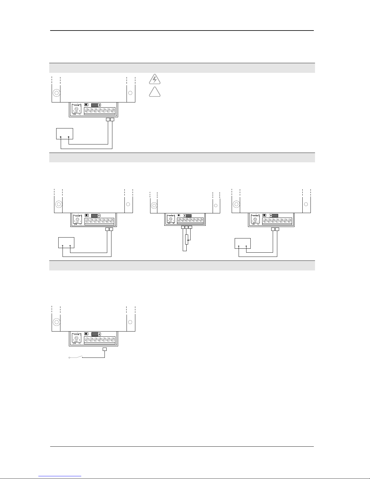
Startup of the micro annular gear pump
Voltage supply
K1K2
Voltage supply
+
–
10...30 VDC
GNDDIR
An_in
S
GND
10 V out
FG
24 VDC
P1
!
Pay attention to the correct polarity of the voltage supply, otherwise
electronics will be damaged.
The length of voltage supply cable should not exceed 10 m, or the
control unit could be damaged by inductance overvoltage.
Analog nominal signal
Potentiometer internal operating mode Potentiometer external operating
mode
0 … 10 V operating mode
connected with jumper pins P3 and P2 connected with the jumper pins P2 and P1 connected with the jumper pins P2 and P1
K1K2
Voltage supply
+
–
10...30 VDC
GND
DIRA
n_in
SGND
10 V out
FG
24 VDC
P1
10 κΩ
K4K5K6
GND
DIR
An_in
SGND
10 V out
FG
24 VDC
P1
K4K5
Sollwert 0...10 V
+
–
GND
DIR
An_in
SGND
10 V out
FG
24 VDC
P1
Digital inputs
Sense of rotation input
− High-Pegel (3 V… U
B
) or open: pump
turn clockwise (to the right)
− Low-Pegel (0 … 0,5 V) oder GND:
Pump turn counterclockwise (to the left)
K3
4...24 VDC
GND
DIR
An_in
SGND
10 V out
FG
24 VDC
P1

6 System integration Operation manual mzr-2961, mzr-4661
Last update: April 2018 Technical data subject to change without prior notice! 25
Digital output
Speed signal output
Digital output: 6 lines per revolution
K7
FG
GNDDIR
An_in
SGND
10 V out
FG
2
4 VDC
P1

7 Start Up / Shut Down Operation manual mzr-2961, mzr-4661
26 Technical data subject to change without prior notice! Last update: April 2018
7 Start Up / Shut Down
7.1 Preparing for operation
After the liquid supply system had been completed, please check once again
the operating conditions of the micro annular gear pump as according to the
following points:
− Are the inlet and outlet tubes or hoses correctly connected?
− Is the entire liquid supply system clean - that means free of particles, foreign
bodies, pollution or swarf?
− Has a filter been installed on the suction side?
− Has a sufficient amount of the right liquid been supplied?
− The pump does not run the risk of a longer dry operation?
− The entire liquid supply system has been checked for leakage?
− Is it possible to stop the pump by an emergency switch if an unexpected
malfunction occurs at the first start?
7.2 Startup of the micro annular gear pump
− Switch on the voltage supply. The micro annular gear pump can now be put
into operation by turning the potentiometer knob, by sending a nominal
external voltage signal.
− Start the filling in of the pump at low or middle speed (1000 - 3000 rpm).
Warning
Avoid dry operation of the pump over a longer time. The pump should be
filled in before it is put into operation.
7.3 Flushing procedure after use
After each service the micro annular gear pump should be carefully flushed
with a non-corrosive, filtered and particle-free flushing liquid (see table 9 /
table 10). During the flushing procedure the pump should operate at about
3000 rpm and if possible against a low pressure (that can be obtained by using
a restrictor, a capillary or similar). The flushing liquid must be compatible with
the delivered liquid and be suitable for solving the remaining liquid rests.
Depending on the application for example water, or isopropanol may be used.
If you have doubts whether a liquid is suitable for this function or not, please
ask the manufacturer of the liquid or HNP Mikrosysteme.

7 Start Up / Shut Down Operation manual mzr-2961, mzr-4661
Last update: April 2018 Technical data subject to change without prior notice! 27
Flush the pump
Selection of flushing
liquid (FL)
Drain the pump
Right
flushing
liquid
Is the
pump
resistant?
no
no
yes
yes
Flushing cycle
End of flushing
cycle
figure 15 Flushing procedure
Warning
Liquids remaining in the pump may crystallize, coagulate or lead to corrosion
and as a consequence impair the work of the micro annular gear pump.
Warning
Please make sure that the pump components and particularly O-rings and
sealing are resistant to the employed flushing liquid (see table 10).
Warning
The flushing liquid (solvent) and the recommended duration of the flushing
procedure depend on the delivered liquid (see table 9). The indicated flushing
liquids are simple recommendations and should therefore be checked by the
user as to their compatibility and suitability.
!
Regulations concerning the use of substances dangerous to health should be
followed!
see table 10 (Resistance of the sealing materials)
see table 9 (Selection of the flushing liquid)
see table 9 (Selection of the flushing liquid)

7 Start Up / Shut Down Operation manual mzr-2961, mzr-4661
28 Technical data subject to change without prior notice! Last update: April 2018
Nature of the handled liquid Flushing cycle
[min]
Suitable flushing liquid
1 Oils, fats, plastifiers 15-20 isopropanol, ethanol, acetone, benzine
2 Solvents (polar + nonpolar) 5-10 isopropanol, ethanol
3 Other organic liquids 10-15 isopropanol , ethanol
4 Refrigerating and cooling agents 15-20 isopropanol, ethanol
5 Neutral watery solutions 20-25 isopropanol, ethanol
6 Basic solutions 25-30 DI-water (deionized water)
7 Organic acids 30-40 isopropanol, ethanol
8 Weak mineral acids 25-30 DI- water
9
Strong mineral acids
35-45
DI- water
10 Strong oxidizing liquids 35-45 DI- water
11 Paints, varnishes, adhesives 50-60 Not specified - for further information
please contact HNP Mikrosysteme.
table 9 Selection of the flushing liquid (solvent) and the duration of the flushing cycle depending on the delivered
liquid.
Warning
Please make sure that the pump components and particularly O-rings and
sealing are resistant to the employed flushing liquid (see table 10).
Shaft sealing O-ring material
Flushing liquid
PTFE (Teflon®),
graphite-
reinforced
UHMWPE FPM
(Viton®)
EPDM FFPM
acetone 0 0 3 0
0
benzene 0 3 1 3 0
benzyl alcohol 0 - 0 2 0
benzine 0 0 0 3 0
butanol 0 - 1 0 0
dimethyl sulfoxide (DMSO) 0 0 3 0 0
ethanol 0 0 0 0 0
isopropanol 0 0 0 0 0
methanol 0 0 2 0 0
methylethylketone (MEK)
0 0 3 1 0
oil / fine mechanics oil 0 0 0 3 0
styrene 0 - 1 3 1
toluene 0 1 2 3 0
water 0 0 0 0 0
xylene 0 1 2 3 0
Legend: 0 ... good suitability 1 ... suitability 2 ... conditional suitability 3 ... labile - ... not specified
table 10 Resistance of the sealing materials depending on the flushing liquid (solvent)

7 Start Up / Shut Down Operation manual mzr-2961, mzr-4661
Last update: April 2018 Technical data subject to change without prior notice! 29
7.4 Shutdown of the micro annular gear pump
During the shutdown of the pump the following steps should be followed
− Flush the pump with a filtered and particle-free flushing liquid (solvent)
(see chapter 7.3)
− After the flushing procedure decrease speed of the pump to 0 rpm
− Fill the pump with a suitable conservation liquid (see chapter 7.4.1)
− Remove the pump from the system (see chapter 7.4.2)
By proceeding as shown in the diagram (see figure 16) you may prepare the
pump for a longer standstill.

7 Start Up / Shut Down Operation manual mzr-2961, mzr-4661
30 Technical data subject to change without prior notice! Last update: April 2018
Legend
FL = flushing liquid
CL = conservation liquid
End of test/operation
Drain the pump
Pump
requires
flushing?
Flushing cycle
Is the
pump
clean?
Selection of
conservation liquid
(CL)
Delivery of
solvents
manipulated
liquid =
conservation
liquid
Flush the pump
Selection of flushing
liquid (FL)
Drain the pump
Right
flushing
liquid
Is the
pump
resistant?
Selection of conservation
liquid (CL)
CL
adequate
Is the CL
compatible
with pump
Is the CL
compatible
with the
last FL ?
Nature of
the CL
Let the gas through
the pump
Fill in CL
Desinstall the
pump
Close the liquid
ports
End of conservation
procedure
New operation after
the conservation
procedure
liquid
yes
no
no
no
no
no
no
no
yes
yes
yes
yes
yes
yes
gaseous
no
yes
Flushing cycle
End of flushing
cycle
End of CL
selection
figure 16 Shutdown procedure
see table 9
see table 10
see table 10
see table 11

7 Start Up / Shut Down Operation manual mzr-2961, mzr-4661
Last update: April 2018 Technical data subject to change without prior notice! 31
7.4.1 Conservation
If the micro annular gear pump operates at irregular intervals or for other
reasons should be put out of operation for a longer period, it should, after
service and flushing procedure (see chapter 7.3), be filled in with a suitable
conservation liquid.
The conservation liquid may be selected from the table 11 depending on the
duration of the standstill and the resistance of the pump to the manipulated
liquid (table 10). The indicated conservation liquids are simple
recommendations and should therefore be checked by the user as to their
compatibility and suitability. The figure 17 presents the diagram of conservation
liquid selection.
Remark: This diagram is repeated as a part of the figure 16 »Shutdown
procedure«.
After the cleansing procedure the pump should be filled with a suitable
conservation agent. You will find a choice of possible conservation liquids in
the table 11.
Selection of conservation
liquid (CL)
CL
adequate
Is the CL
compatible
with pump
Is the CL
compatible
with the
last FL ?
yes
no
no
no
yes
yes
figure 17 Selection of the conservation liquid (CL)
see table 10 (resistance of the sealing materials)
see table 11 (Selection of conservation liquid)

7 Start Up / Shut Down Operation manual mzr-2961, mzr-4661
32 Technical data subject to change without prior notice! Last update: April 2018
Liquids
Solubility in
water
Compatibility
with the
delivered liquid
Duration of
storage Breakaway
torque Toxicology Viscosity Description
isopropanol + + o o o + solvent for organic compounds, cosmetics, essential oils,
waxes and esters, antifreezers, antiseptic agents
acetone + + o o o + solvent for a number of organic compounds, unlimited
solubility in water, dissolves natural and synthetic resins, fats,
oils and commonly used plastifiers
ethanol + + o o o + solvent for organic compounds, fats, oils and resins
DI-water
+ + - - + + solvent for many organic and mineral liquids
fine mechanics
oil
- - + + + + cleansing and protective action (dissolves fats, tar, rubber or
adhesive substances, protects against corrosion)
hydraulic oil - - + + + - lubricating and preserving properties (Warning: may resinate
or deteriorate with time)
nitrogen - + + + o + is not a solvent, may leave deposits after drying out
air /
compressed air
+ + + + + is not a solvent, may leave deposits after drying out
Legend: + ... good/suitable o ... satisfactory; - ... bad/inadequate
table 11 Selection of the conservation liquid
In order to prevent dust particles and foreign bodies from penetrating into the
pump or the conservation liquid from leaking out, please secure the liquid input
and output with the delivered protective plugs or screws.
Warning
Water or deionized water (DI-water) should not be used as conservation
agents. These liquids germinate already after a few days and build a biofilm
which can later block the pump.
7.4.2 Dismantling of the system
− Put the drive out of operation by turning down speed to 0 rpm and by
switching off the voltage supply. Make sure that the procedure described in
the chapter 7.3 has been completed.
− Now that the pump has been stopped you may remove it from the system.
− Protect the inlet and outlet openings of the pump with adapted protective
caps or screws.

7 Start Up / Shut Down Operation manual mzr-2961, mzr-4661
Last update: April 2018 Technical data subject to change without prior notice! 33
7.5 Trouble shooting
If the pump does not start to operate or stops the operation abruptly, please
proceed as follows:
Try to liberate the micro annular gear pump:
− by turning the potentiometer knob back and forth or by sending an analog
voltage signal
− via the control software
− by pressing with a syringe a suitable flushing liquid (see table 9 and table 10)
through the micro annular gear pump
− by changing the operating direction of the pump.
If these measures turn out to be ineffective, please contact the service staff of
HNP Mikrosysteme (see chapter 11) and send the pump back to the
manufacturer for inspection.
Warning
You should under no condition try to dismantle the pump by yourself. This
may cause damage to the pump components and consequently annul your
warranty claims.
7.6 Return of the micro annular gear pump to the manufacturer
For the return of a micro annular gear pump and components that have already
been employed, please follow the instructions:
− drain any remaining rests of the delivered liquid from the pump
− flush the pump with an adapted solvent
− remove the filter elements from integrated or loosely delivered filters
− protect all openings against dust with the delivered protective plugs or
screws
− return the pump in its original packing
The service personnel which carries out the repair should be informed about
the condition of the used micro annular gear pump. This is done by means of
the "Declaration of media in contact with the micro annular gear pump and
components" (see chapter 17). This form may also be downloaded from the
web site www.hnp-mikrosysteme.de/download.
!
The "Declaration of media in contact with the micro annular gear pump and
components" must imperatively be filled in. The nature of liquid which entered
into contact with the micro annular gear pump and the components must be
specified.
In case of non-compliance, the sender will be liable for any resulting injure to
persons or any object damage.

8 Accessories for microfluidic systems Operation manual mzr-2961, mzr-4661
34 Technical data subject to change without prior notice! Last update: April 2018
8 Accessories for microfluidic systems
The accessory range for the liquid delivery systems of HNP Mikrosysteme
comprises complementary equipment such as supplementary modules, hoses,
tubing, fluid connection fittings, filters and non-return valves that are best
adapted to your micro annular gear pump. We will eagerly share our long date
experience as far as component selection is concerned.
9 Non-liability clause
HNP Mikrosysteme GmbH shall not be liable for damages resulting form the
non-respect of instructions comprised in this operating manual.
It remains at the responsibility of the user to conform to all laws, rules and
regulations in force. This applies above all to the handling of aggressive,
poisonous, corrosive and other dangerous liquids as well as to the
electromagnetic compatibility (EMC).

10 Problems and their removal Operation manual mzr-2961, mzr-4661
Last update: April 2018 Technical data subject to change without prior notice! 35
10 Problems and their removal
Disturbance Cause Solution
1 The pump does not start operation.
No power supply
Check the power supply.
2 The pump does not deliver any
liquid.
No liquid in the primary tank. Fill the recipient/tank with liquid.
Presence of air or gas in the pump The pump cannot run dry against the system
pressure. Fill in the pump at no pressure or at
reduced system pressure.
Malfunction of the liquid supply system
(such as in the delivery tube or hose, the
needle or external non-return valve)
Check the components for possible
disturbances to be eliminated. Cleanse the
accessories if needed.
Failure of the electric installation. Check the electric installation for the correct
cable configuration, loose contacts, etc.
The pump did not receive the start signal or
start conditions are not fulfilled.
Check if the start conditions have been
fulfilled start signals (PLC, start input) and the
programming.
Read the operating manual for the motor
control unit.
3 The pump does not start to operate. The pump does not take in the liquid. The tubing on the suction side is too long or
has a too small internal diameter (a too low
NPSHA value).
The tubing or the fluid connection on the
suction side are not tight. Please check the
intake connection and the tubing.
Air bubbles in the system
(tubes, valves, ...)
If the viscosity of the liquid is too high, apply
pressure on the suction side.
Check the pressure exerted on the primary
liquid tank.
An external non-return valve does not open.
Check the non-return valves.
Submit the non-return valve to a higher
pressure, so that the pump may fill in.
4 The motor turns, but the pump
does not operate.
No liquid in the pump Fill the pump with liquid.
Air bubbles in the liquid supply system
(tubing, valves, ...)
Fill the pump and the liquid supply system
with liquid.
The non-return valve does not open. Rinse the non-return valve.
Blocked delivery tubing or needle Cleanse, flush or exchange the delivery
tubing or dosage needle.
The coupling between the motor and the
pump is out of position.
Return the pump to the manufacturer.
The pump shaft is broken. Return the pump to the manufacturer.
5 The pump is filled with liquid, but
does not pump it.
Adapt the motor current of the control.
Contact the manufacturer of the pump.
Presence of particles in the delivered liquid
or blockage of the pump
Check the motor error status with the Motion
Manager software.
Try to liberate the pump by making it operate
in a reverse direction for 1 s with
- 1000 rpm.
Flush the pump with a syringe.
Return the pump to the manufacturer for
cleansing. Use a filter, flush the liquid delivery
system.
The non-return valve does not open. Rinse the non-return valve.
Blockage of the delivery tubing or the Cleanse, flush or exchange the delivery

10 Problems and their removal Operation manual mzr-2961, mzr-4661
36 Technical data subject to change without prior notice! Last update: April 2018
Disturbance Cause Solution
needle tubing or the needle.
Air bubbles in the liquid delivery system
(tubing, valves)
Fill in the pump and the liquid delivery system
with liquid.
6 Dosage volume does not
correspond to the desired values.
Air bubbles in the liquid delivery system
(tubing, valves ,...) and the pump
Vent the liquid delivery system and check for
untight fluid connections.
Pump shows cavitation. Too long or too narrow intake tubing.
Shorten the intake tubing or change the
position of the pump.
Polluted or too small filter Change the filter to a new or bigger one.
The non-return valve does not open. Rinse the non-return valve.
7 Speed of the pump cannot be
adjusted.
Defective electric installation Check the electric installation for correct
cable configuration and loose contacts.
Defective drive control Return the drive control unit to the
manufacturer.
Encoder cable disconnected The motor works at high speed. Check the
installation, return the pump to the
manufacturer for checkup.
8 Liquid drops from the dosing
needle.
The non-return valve does not close. Rinse the non-return valve.
Too high pressure on the primary liquid
tank
Stop the delivery of compressed air on the
primary liquid tank.
The liquid tank is at a higher level than the
dosing needle.
Place the liquid tank at the same or slightly
lower level as the pump.
9 Liquid leaks out of the sealing
module.
Too high pressure on the sealing liquid
supply cartridge or defective sealing
Stop pressurizing the sealing liquid supply
cartridge. If needed return the pump to the
manufacturer.
10 Dosage volume decreases with
time.
Polluted filter Exchange the filter.
Deposits in the pump Flush the pump or return it to the
manufacturer for dismantling and cleaning.
The pump is worn after a long operating
period or after use with abrasive liquids.
New definition of the calibration factor of the
pump, by modifying the pump characteristics
graph necessary.
11 Leakage from the pump The sealing does not function correctly. Return the pump to the manufacturer.
12 Leakage from the coupling
assembly
Defective shaft seal Return the pump to the manufacturer in
order to change the shaft sealing.
13 Leakage from the fluid connections Untight locking rings Exchange or tighten the fluid connections,
exchange the fluid connection.
14 Air bubbles on the delivery side. Loose fluid connections (particularly on the
induction (suction) side)
Check and tighten the fluid connections.
The shaft seal is untight or worn. Return the pump to the manufacturer.
15 The error status of the pump cannot
be retrieved.
No connection with the pump Check the supplied voltage.
Check the connection of the interface with
the null-modem cable. Replace the cable if
needed.
The motor control unit does not respond. Turn off the voltage supply for a short time,
then turn it on again. Start the pump
automatically with the integrated control
unit.
16 Minimal leakage during standstill No error, cause relative to the operating
principle
Use a non-return valve.
Place the liquid tank at the same or slightly
lower level as the pump.
17 Excess temperature The surface of the pump is hot. Clean the surface of the pump, rinse the
pump.
The pump operates with difficulty. The pump should be flushed.
Particles in the delivered liquid or deposits
in the pump
The operation of the pump should
immediately be stopped! Return the pump to

10 Problems and their removal Operation manual mzr-2961, mzr-4661
Last update: April 2018 Technical data subject to change without prior notice! 37
Disturbance Cause Solution
the manufacturer for cleansing.
Noise of beveling The operation of the pump should
immediately be stopped! Return the pump to
the manufacturer for cleansing and repair.
The motor surface or the motor interior are
too hot.
High temperature indicator in the drive is on.
The motor has been shut down by the
thermistor. Return the pump to the
manufacturer.
18 The pump is noisy. Wear out of the pump or defective
components.
Do not continue to operate the pump, return
it to the manufacturer for maintenance.
19 Overcurrent Particles in the delivered liquid Rinse the pump.
The pump operates with difficulty. Dosing needle is damaged. Needle should be
cleansed, flushed or exchanged.
Tubing on the delivery side, dosing needle or
the non-return valve is blocked. Cleanse,
flush or exchange the components.
Deposits inside the pump. Flush the pump. If necessary return the pump
to the manufacturer.
20 Undervoltage Voltage supply < 12 VDC Check the power supply 24 VDC
21 Overvoltage Voltage supply > 28 VDC Check the power supply 24 VDC. The drive
control unit may be damaged. Return the
pump to the manufacturer.
table 12 Problem shooting
!
If a disturbance that has not been mentioned in the above list, or that makes
the use of the micro annular gear pump unsafe appears, please stop the
operation of the pump without delay and contact HNP Mikrosysteme (see
chapter 11). If needed return the pump to the manufacturer for checkup.

11 EC Directive Operation manual mzr-2961, mzr-4661
38 Technical data subject to change without prior notice! Last update: April 2018
11 EC Directive
A Directive or EC Directive is a legal instrument of the European Community
addressing at the member states and forcing them to implement specific
regulations or targets. Leastwise, micro annular gear pumps are covered, by the
scope of application of the following Directives: The following directives are of
importance for the user of the described micro annular gear pumps:
Low-Voltage Directive (2014/35/EU)
The Low-Voltage Directive is not relevant for micro annular gear pumps
described in this manual, because the supply voltage is limited to a maximum of
30 VDC.
Machinery Directive (2006/42/EU)
A micro annular gear pump is a machine and is consequently covered by this
Directive. However, it may be a part of a machine or installation.
EMC Directive (2014/30/EU)
The Directive on Electromagnetic Compatibility (EMC) applies to all electronic
and electrical devices, installations and systems. Consequently, the Motion
Controller of the micro annular gear pump is covered by the EMC Directive.
RoHS Directive
(2011/65/EU)
To our knowledge our products delivered to you do not contain substances or
applications in concentrations that are forbidden by this directive. No
substances contain our products delivered to you after our current knowledge
in concentrations or application, the
placing on the market in products
according to the valid requirements forbade to the Directive.
WEEE Directive (2002/96/EU)
Disposal of micro annular gear pumps has to be environmentally sound.
All materials and liquids have to be recycled in accordance with the relevant
regulations. Electrical parts can not be disposed of as household waste. They
have to be delivered to designated collection points.

11 EC Directive Operation manual mzr-2961, mzr-4661
Last update: April 2018 Technical data subject to change without prior notice! 39
REACH regulation (EC) No. 1907/2006
HNP Mikrosysteme is not a manufacturer or importer of chemical substances
subjected to registration, but in terms of regulation, a downstream user. As
downstream user, we conduct the necessary communication with our suppliers
to ensure future deliveries of all components necessary to us. We will notify you
of all relevant, changes in our products, their availability and the quality of
parts/products delivered by us within our business and coordinate the
appropriate action in individual cases with you. Previous inspection did not
show any limitation in the supply of material from our upstream suppliers.
11.1 Electromagnetic Compatibility (EMC)
Electromagnetic compatibility is defined as the ability of a electric or electronic
device to function satisfactorily as intended in its electromagnetic environment
without introducing intolerable electromagnetic disturbances in that
environment.
11.1.1 EMC Directive and Standards
Comformity was proven by proof of compliance with the following harmonized
standards by the company Dr. Fritz Faulhaber:
− EN 61000-6-4 (10/01): Generic standards – Emission standard for industrial
environments
− EN 61000-6-2 (10/01): Generic standards – Immunity for industrial
environments
These standards prescribe certain standardised tests for the emittedinterference and interference-immunity tests. The following tests are required
due to the connections on the controller:
Generic Standard on Emitted
Interference:
Description
EN 55011 (05/98)+A1(08/99)+A2(09/02): Radio disturbance characteristics
Generic Standard on Interference
Immunity
EN 61000-4-2 (05/95)+A1(4/98)+A2(02/01): Electrostatic discharge immunity test
EN 61000-4-3 (04/02)+A1(10/02): Radiated, radio-frequency, electromagnetic field immunity
test
EN 61000-4-4 (09/04): Electrical fast transient/burst immunity test
EN 61000-4-5 (03/95)+A1(02/01
Surge immunity test
EN 61000-4-6 (07/96)+A1(02/01): Immunity to conducted disturbances, induced by radio-
frequency fields
EN 61000-4-8 (09/93)+A1(02/01): Power frequency magnetic field immunity test
Table 1 Standards Summary
All tests were conducted successfully.

11 EC Directive Operation manual mzr-2961, mzr-4661
40 Technical data subject to change without prior notice! Last update: April 2018
11.1.2 Information on use as intended
For micro annular gear pumps, note the following:
Requirement for the intended operation is the operation according to the
technical data and the manual.
Restrictions
If the micro annular gear pumps are used at home, in business or in commerce
or in small businesses, appropriate measures must be taken to ensure that
emitted interferences are below the permitted limit a values!

11 EC Directive Operation manual mzr-2961, mzr-4661
Last update: April 2018 Technical data subject to change without prior notice! 41

12 Declarations of conformity Operation manual mzr-2961, mzr-4661
42 Technical data subject to change without prior notice! Last update: April 2018
12 Declarations of conformity
The delivered micro annular gear pump falls within scope of the following EC
directives:
− Machinery Directive (2006/42/EU)
− EMC Directive (2014/30/EU)
You may request the declarations of conformity for the micro annular gear
pumps from us separately.

EC-manufacturer’s certificate
(following Machinery Directive 2006/42/EU)
We hereby declare that the following micro annular gear pump of the magnetic
hermetic series:
mzr-2961, mzr-4661
are intended for installation into another machinery/plant and that start of
operation is forbidden until it is identified that the machinery/plant into which
these micro annular gear pumps shall be installed corresponds to the
regulations of the EC guidelines regarding safety and health requirements.
We confirm the conformity of the product described above to the following
standards in terms of applied directives
− Machinery Directive (2006/42/EU)
Applied standards are particularly
DIN EN 809 DIN EN 60204-1 DIN EN 294
DIN EN ISO 12100 part 1 DIN EN 953
DIN EN ISO 12100 part 2 UVV
This statement does not warrant any characteristics in terms of product liability.
Please note the safety instructions in the manual.
Mr. Lutz Nowotka, HNP Mikrosysteme GmbH, Bleicherufer 25, D-19053
Schwerin is authorised to compile the technical file according to Annex VII A.
Date: 17 May 2013
Signature manufacturer:
Dr. Thomas Weisener
CEO


EC-manufacturer’s certificate
(following EMC Directive 2014/30/EU)
We hereby declare that the following micro annular gear pump of the magnetic
hermetic series:
mzr-2961, mzr-4661
are intended for installation into another machinery/plant and that start of
operation is forbidden till it is identified that the machinery/plant into which
these micro annular gear pumps shall be installed corresponds to the
regulations of the EC guidelines regarding safety and health requirements.
We confirm the conformity of the product described above to the following
standards in terms of applied directives
− EMC Directive (2014/30/EU)
Applied standards are particularly
EN 61000-6-4 (10/01): Generic standards – Emission standard for
industrial environments
EN 61000-6-2 (10/01): Generic standards – Immunity for industrial
environments
This statement does not warrant any characteristics in terms of product liability.
Please note the safety instructions in the manual.
Date: 19 April 2016
Signature manufacturer:
Dr. Thomas Weisener
CEO


13 Service, maintenance and warranty Operating manual mzr-2961, mzr-4661
Last update: April 2018 Technical data subject to change without prior notice! 47
13 Service, maintenance and warranty
Maintenance of the micro annular gear pump should be carried out depending
on the delivered liquid:
− for lubricating liquids after 6000 working hours, but not later than
15 months after the initial operation
− for non-lubricating liquids, crystallizing liquids or liquids containing particles,
after 4000 working hours but not later than 12 months after the initial
operation. If during the first inspection no substantial wearout of the pump
is observed, the following inspection under the same working conditions
should be performed after 6000 working hours, yet not later than
15 months following to the last inspection.
If during the first inspection the pump shows a particularly strong wearout, the
maintenance intervals should be readapted to the changing operating
parameters.
In order to prevent a strong wearout of the pump, the pump should be shut
down properly after every application as described in the chapter 7.3.
A supplementary flushing procedure with a neutral flushing liquid
(see chapter 7.3) also slows down the wearout process of the pump.
!
It is not allowed to open or dismantle the micro annular gear pumps. The
warranty extincts with the expiry of the legal warranty period or with the
opening of the pump. Furthermore HNP Mikrosysteme cannot give any
warranty of exchange for parts whose damage result from incorrect use.
!
For service and maintenance please return your micro annular gear pump to
HNP Mikrosysteme. You will find the address on the cover of the present
operating manual.
!
The declaration of media (liquids) having had contact with the micro annular
gear pump and components must imperatively be completed. The nature of
media (liquids) must be specified. In case of non-compliance the sender will be
liable for any resulting injure to persons or any object damage.
!
Sealing elements, rotors and shaft are parts that undergo wear and will be
replaced by HNP Mikrosysteme GmbH during maintenance depending on their
degree of wear.

14 Contact person Operating manual mzr-2961, mzr-4661
48 Technical data subject to change without prior notice! Last update: April 2018
14 Contact person
Development and application assistance, service and accessories
Mr. Sven Reimann
Phone +49| (0) 385|52190-349
Service and maintenance
Mr. Steffen Edler
Phone +49| (0) 385|52190-307
Drive and control technology
Mr. Lutz Nowotka
Phone +49| (0) 385|52190-346

15 Legal information Operating manual mzr-2961, mzr-4661
Last update: April 2018 Technical data subject to change without prior notice! 49
15 Legal information
Marks
mzr
®
is a registered German trademark of HNP Mikrosysteme GmbH.
MoDoS
®
is a registered German trademark of HNP Mikrosysteme GmbH.
µ-Clamp
®
is a registered German trademark of HNP Mikrosysteme GmbH.
HNPM
®
is a registered German trademark of HNP Mikrosysteme GmbH.
Teflon
®
is a registered trademark of DuPont.
Viton
®
is a registered trademark of DuPont Dow Elastomers.
Kalrez
®
Spectrum™ is a registered trademark of DuPont.
PEEK™ is a registered trademark of Victrex plc.
HASTELLOY
®
is a registered trademark of Haynes International, Inc.
Aflas
®
is a registered trademark of ASAHI Glass Ltd.
Microsoft
®
, Windows® are registered trademarks of Microsoft Corporation in
the USA and in the other countries.
Cavro
®
is a registered trademark of Tecan Systems, Inc.
Other product names or descriptions not mentioned above are possibly
registered trademarks of related companies.
Patents
Micro annular gear pumps (and housings) are protected by assigned patents:
EP 1115979 B1, US 6,520,757 B1, EP 852674 B1, US 6,179,596 B1,
EP 1354135, US 7,698,818 B2. Patents pending DE 10 2011 001 041.6,
PCT/IB2011/055108, EP 11 81 3388.3, US 13/884,088, CN 2011 8006 5051.7,
HK 13 11 2934.9, DE 10 2011 051 486.4, PCT/EP2012/061514,
EP 12 728264.8, US 9,404,492 B2, CN 2012 8003 8326.2. In the US, Europe
and China additional patents are pending.

16 Safety information for the return of already
employed micro annular gear pumps and components Operating manual mzr-2961, mzr-4661
50 Technical data subject to change without prior notice! Last update: April 2018
16 Safety information for the return of already
employed micro annular gear pumps and components
16.1 General information
The operator carries the responsibility for health and safety of his/her
employees. The responsibility extends also to employees not belonging to the
company that have a direct contact with the micro annular gear pump and its
components during repair or maintenance works. The nature of media (liquids)
coming into contact with the micro annular gear pump and its components
must be specified in the corresponding declaration form.
16.2 Declaration of media in contact with the micro annular gear pump
The staff performing the repair or maintenance works must be informed about
the condition of the micro annular gear pump before starting any work on the
device. The "Declaration of media in contact with the micro annular gear
pump" should be filled in for this purpose.
The declaration should be sent directly to the supplier or to the company
designated by the supplier. A second copy of the declaration must be attached
to the shipment documents.
16.3 Shipment
The following instructions should be observed for the shipment of the micro
annular gear pump.
− drain the pump from any remaining liquid
− flush the pump with an adapted flushing liquid
− remove the filter elements from the integrated or loosely delivered filters
− all the openings should be air-tight plugged
− return the pump in the original packing

17 Declaration of media in contact
with the micro annular gear pump and its components Operating manual mzr-2961, mzr-4661
Last update: April 2018 Technical data subject to change without prior notice! 51
17 Declaration of media in contact
with the micro annular gear pump and its components
Type of the device
Pump type/serial number/article no.:
Operating hours/running time:
Number of delivery note or delivery date:
Reason of return:
Contact with media (liquids)
The micro annular gear pump was in contact with:
and has been rinsed with:
Product info sheet / Material Safety Data Sheet: yes* no
* Please attach file
or is available on the following web site: www.
If a pump which had contact with dangerous substances could not be properly cleansed prior to shipment,
we reserve the right to entrust a specialized company with cleansing of the device. The return of the pump
in original packing is advisable. It is necessary in order to protect the employees and delivery staff.
Nature of media contact:
explosive
toxic (toxic byproducts)
carcinogenic
irritant
oxidizing
radioactive
microbiological
corrosive
sensitive to moisture
pH-value: approx. to
other:
R-statements: S-statements:
Declaration
Hereby I/we affirm that the stated information is complete and correct. Micro annular gear pump and
accessories are shipped in conformity with the applicable regulations.
company:
division:
street, no.:
ZIP/city:
country:
city, date:
Mrs Mr title:
name:
phone:
e-mail:
authorized signature /
company stamp:

18 Appendix Operating manual mzr-2961, mzr-4661
52 Technical data subject to change without prior notice! Last update: April 2018
18 Appendix
− Layouts

18 Appendix Operating manual mzr-2961, mzr-4661
Last update: April 2018 Technical data subject to change without prior notice! 53
6
1
2
5
0,079
±10
0,276,9
22
2
500
0,866
±0,394
19,685
61
,6
2,
426
68,5
+
-
1,4
0,9
2,696
+
-
0,055
0,035
(
1:1
)
Fla
t cable
s AWG
26
Connec tor Micro-Fit
Orientati on of ribbon
cabl
e not
defined
0,079
±0,002
2
±0,0
5
4
±0,05
0,157
±0,00
2
SCALET
OLER
ANC
ES
01.10.14
DRAW
N
AMZ
1
Dr
awi
ng i
s s
ubj
ect
to
cha
nge
wit
hou
t n
oti
ce.
gespeichert am: 0110 14 08:08:03
Dim
ens
ion
s ar
e m
ill
ime
ters
ne
xt
to [
inc
hes
].
AMZ
D
-
19
0
53
S
c
hw
er
i
n
01-06-046-D001-02
DIN
ISO
27
68
m-H
MST
DIN A3
micro annular gear pump
dimensioned drawing
SH
EET
2:1
D
d
rawn
R
EV.
ISS
UE
DATE
L
ANG
.
AP
PRO
VED
CH
ECK
ED
D
RAW
ING
NU
MBER
K
IND
OF
DOC
UME
NT
ST
ATE
OF
DOC
UME
NT
DE
SCR
IPTI
ON
HNP
Mik
ros
yst
eme
Gmb
H
Bleicherufer 25
en
Positi on of this
flats not defined
mzr -2961
c
an
ne
d
m
o
to
r
2
23
2
B
X4
S
C
ap
p
ro
x.
11
5
g
mzr-4661
Pin allocation
1
U
p
(24 VDC)
2
U
mot
(2
4 V
DC)
3 GN D
4
U
ns
oll
5 DI R
6
FG
Pin allocation
1
U
p
(24 VDC)
2
U
mot
(2
4 V
DC)
3 GN D
4
U
ns
oll
5 DI R
6
FG
figure 18 Data sheet of the micro annular gear pump mzr-4661

18 Appendix Operating manual mzr-2961, mzr-4661
54 Technical data subject to change without prior notice! Last update: April 2018
6
1
2
5
Orientati on of ribbon
Con
nec
tor
Micro-Fit
O-
ring (
2x)
Fl
at
cabl
es AWG 26
ca
ble
no
t defined
Po
siti
on
of this
fla
ts not
defined
6,5
0
,256
0,0792 0,1
57
1
,02
4
2
6
35 1,378
4
4 0,157
01-06
-0
4
6-
D001-03
m
i
cr
o
a
nn
u
lar gear pump
S
CALE
01
.1
0
.1
4
T
OLER
ANC
ES
g
e
sp
ei
c
he
rt
am: 011 014 07:50:36
D
IN A
3
A
MZ
Drawing is subject to change without notice.
Di
m
en
s
io
ns
are millimeters next to [inc hes].
M
WO
M
ST
D
-1
9
05
3
S
ch
werin
1
D
I
N
IS
O
2
7
68 m-H
D
a
p
p
ro
ve
d
R
E
V.
IS
S
UE
DATE
L
A
NG
.
APP
ROV
ED
CHECKED
MA
TER
IAL
KIND OF DOCUMENT
STA
TE
OF
DOCUMENT
DES
CRI
PTI
ON
dime
nsi
one
d drawing
S
H
EE
T
2:1
D
R
AW
IN
G
N
U
MBER
DRAWN
H
NP
M
i
kr
os
y
steme GmbH
Bleicherufer 25
e
n
(1:1)
capti
ve cylinder head screw M3x12 DIN 912
with fi
xing O-ring 2x1,3 FP M
±0,0
20
0,079
±0,
5
2
2
0,528
0,008
--0,004
-
0,1
0,2
1,10228
0,866
2,4
26
±0,
039
22
±0,
394
19,
685
0,7
87
±1
20
61
,8
7 0,276
±
10
0,077
5
00
13,4
-
30
-00,1
1,181
-
0,000
0,004
Pi
n a
lloc
ation
1
U
p
(
24
VD
C)
2
U
mot
(24
VD
C)
3 GND
4
U
ns
o
ll
5
D
IR
6 F
G
mz
r-2
961
M2.1
1,
5x1
ca
n
ne
d
m
ot
or 2232 BX4 SC
app
rox.
14
5 g
m
zr
-4
6
61
M2
.1
2
x1
figure 19 Data sheet of the micro annular gear pump mzr-4661 configuration with manifold assembly M2.1
 Loading...