

HN-electronic PD110-13LB, PD110-13MB, PD110-14HB, PD110-10HB, PD110-10LB Datasheet
...
HN Electronic ComponentsGmbH•Birkenweiherstr.2•D-63505Langenselbold
Tel. (06184) 92780 • Fax(06184) 62316 • http://www.hn-electronic.de
68
PROTEK
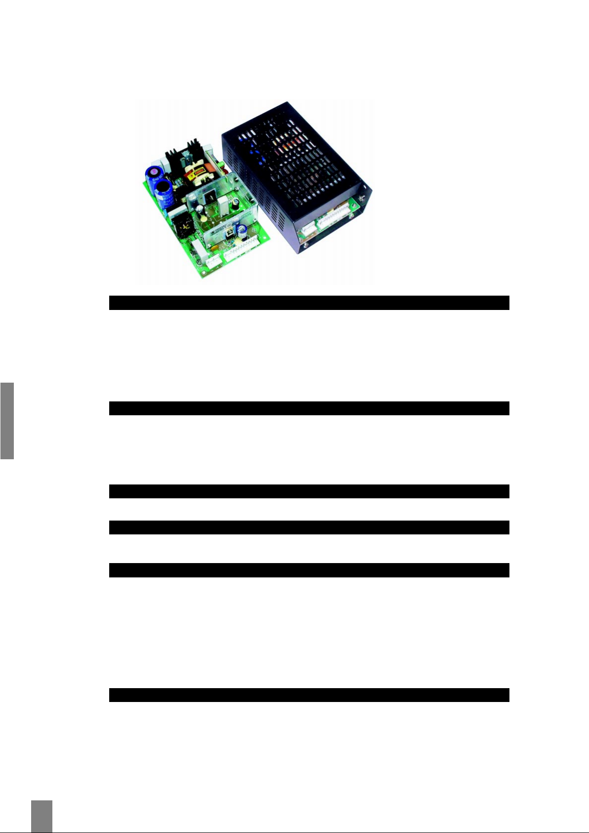
110 Watt DC-Smart Power
PD 110 Wide-Ranging Compact-Serie
Besondere Merkmale Features
Mehrfachausgänge Multiple output
Weiter Eingang Wide input
Hoher W irkungsgrad High efficiency
100% Burn-in 100% burn in
Kompakter Aufbau Low profile package
Überlast- und kurzschlußfest Overload, short circuit protection
Gehäuseversion Boxed type
Anwendung Application
Rechnersysteme Computer applications
MSR Control equipments
Mikroprozessorsysteme Microprocessor systems
KFZ / Boote Cars / boats
Technische Daten Specification
(bei 25°C Umgebungstemperatur) (at 25°C ambient temperature)
Eingangsdaten Input Specifications
Eingangsspannung Input voltages 10…20 (L), 18…36 (M), 36…92 (H) VDC
Ausgangsdaten Output Specifications
Leistung Power 110 Watt
Wirkungsgrad Efficiency typ. 70%
Schaltfrequenz Switching frequency 36 kHz
Regelabweichung Regulation
Eingang Line ±0.5% max. at full load
Hauptausgang Main output <3%
Kreuzregelung Cross <5%
Ausregelzeit ±1% Recovery time ±1% 500µs/25% load step
Restwelligkeit Ripple and noise <1% max. P-P
Allgemeine Daten General Specifications
Betriebstemperatur Operating temperature 0°C…70°C
Lagertemperatur Storage temperature −40°C … +85°C
Temperaturkoeffizient Temperature coefficient 0.04% / K
Leistungsrücknahme Derating ab 50°C: 2.5%/°C
Isolationsspannung Withstandvoltage 1000 V DC input/output
Überspannungsschutz Overvoltage Protection typ. 112…132% of main outp.
Leistungsbegrenzung Power Limitation 120…150% totalpower
MTBF MTBF >100,000 h @25°C, MIL HDBK 217E
110W
DC/DC
OPEN
FRAME/
CASE
Technische Änderungen vorbehalten.
Technical specifications are subject to change without notice.
MEMO:
HN Electronic Components GmbH • Birkenweiherstr. 2 •D-63505 Langenselbold
Tel. (06184) 92780 • Fax(06184) 62316 • http://www.hn-electronic.de
69
110 Watt DC-Smart Power
PD 110 Wide-Ranging DC-Compact-Serie
Bestell-Information / Order Information
Modell Ausgang1 Ausgang 2 Ausgang 3 Ausgang 4 Max.Output
Output 1 Output 2 Output 3 Output 4 Power
V
nomIminImax
Tol V
nomIminImax(Ipeak
)Tol V
nomIminImax
Tol V
nomIminImax
Tol Watt
PD110-10 5V 0A 22A 3% (N/A) (N/A) (N/A) 110
PD110-12 12V 0A 9.0A 2% (N/A) (N/A) (N/A) 110
PD110-13 15V 0A 7.5A 2% (N/A) (N/A) (N/A) 110
PD110-14 24V 0A 4.5A 2% (N/A) (N/A) (N/A) 110
PD110-16 30V 0A 3.6A 2% (N/A) (N/A) (N/A) 110
PD110-23 +5V 0A 10A 3% +12V 0A 5A (9.0A) 3% (N/A) (N/A) 110
PD110-31 +5V 0A 10A 3% +12V 0A 5A (9.0A) 3% −12V 0A 1A 4% (N/A) 110
PD110-32 +5V 0A 10A 3% +15V 0A 4A (7.5A) 3% −15V 0A 1A 4% (N/A) 110
PD110-40 +5V 0A 10A 3% +12V 0A 5A (9.0A) 3% −12V 0A 1A 4% −5V 0A 1A 4% 110
PD110-41 +5V 0A 10A 3% +15V 0A 4A (7.5A) 3% −15V 0A 1A 4% +24V 0A 1A 4% 110
PD110-42 +5V 0A 10A 3% +12V 0A 5A (9.0A) 3% −12V 0A 1A 4% +12V 0A 1A 4% 110
PD110-45-1 +5V 0A 10A 3% +12V 0A 5A (9.0A) 3% −12V 0A 1A 4% +24V 0A1.5A 10% 110
PD110-45-2 +5V 0A 10A 3% +24V 0A 3A (5.0A) 3% −12V 0A 1A 4% +12V 0A 1A 4% 110
PD110-46 +5V 0A 10A 3% +15V 0A 4A (7.5A) 3% −15V 0A 1A 4% −5V 0A 1A 4% 110
Andere Typen und Spannungenauf Anfrage • Other models and configurations on request.
Input ranges – Eingangsspannungsserien: L=10…20 VDC, M=18…36 VDC, H=36…72 VDC
Vermerk
1-Die Dauerleistung darf 80 W (M&H-Serie) bzw.75 W (L-Serie) ohne Fremdkühlung und 110 W (M&H-Serie)
bzw. 90 W (L-Serie) mit Fremdkühlung nicht übersteigen.
2-Peakstrom weniger als 60 s, mit einer relativen Dauer von weniger als 10%.
3-Restwelligkeit, bei 20 MHz Bandbreite unter Verwendung einer 10 µF Kapazität parallel zu einem 0,1 µF Kera-
mikkondensator sowie einer Spule mit 10Windungen gemessen.
Bestellbeispiel:
PD110-40 HB H=Eingangsspannung B=Mechanik
Remarks
1-The maximum continuous output powermust not exceed80 W (M&H series) resp. 75 W (L series) without con-
vection cooling and 110 W (M&H series) resp. 90 W (L series) withconvection cooling.
2-Peak current lasting less than 60 s, with duty cycle less than 10%.
3-Ripple and noise is measured at 20 MHz bandwidth limited by using a 10 in twisted wire terminated with a
10 µF capacitor in parallel with a 0.1 µF ceramic cap.
Order example:
PD110-40 HB H=input range B=mechanic version
Mechanik Mechanical
L×B×H L×W×H PCB 178 × 108 × 47 mm / 7 × 4.25 × 1.85 in GEWICHT /WE IGHT
Case 190 × 116 × 60 mm / 7.48 × 4.57 × 2.36 in 640 g (PCB-Version)
A offen,Bfür L-Winkel, C für Gehäuse A open,Bfor L-Bracket, C for Case
siehe Seite83 see page 83
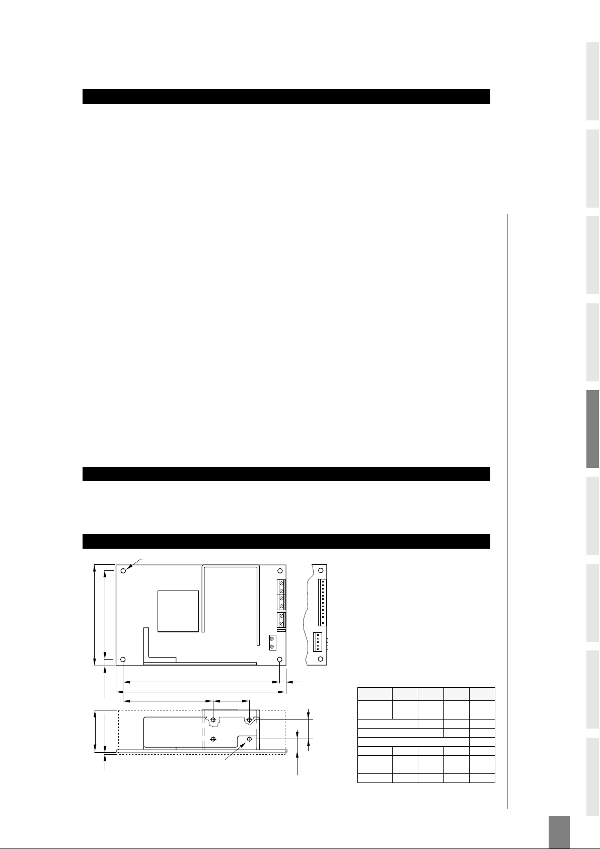
PIN-Belegung und Zeichnung / Pin Assignments & Drawing, mm (inch)
178 (7.0)
4x Ø4,0 (0.157DIA.)
108 (4.25)
95,3 (3.75)
6,4 (0.25)
2,5 (0.10)
47,0 (1.85)
165 (6.5)
P1
6,4
(0.25)
85,3 (3.35) 39,4
(1.55)
P2
1
13
GROUND
-
INPUT
+INPUT
12,0
(0.47)
25,4
(1.0)
1
2
3
4
5
6
DC
OUTPUT
P2
P3
DC
INPUT
-
+
Gewindeeinsätze für 4x 6-32UNC
bzw. M3 Schrauben
aoea0,5(00)
Input and output connector use as
mini terminal block a s standard
allowing wires up to 4mm² (AWG#12)
Input and output connector can be
Molex KK type on request.
(Standard Mini-Verbindung)
(Option: Molex-Stecker)
OUTPUT CONNECTIONS
PINs
SINGLE DUAL TRIPLE QUAD
Out 1
1,2, 3,
8, 9
1,2, 3, 1,2, 3, 1,2, 3,
Out 2
8,9 8,9 8,9
Out 3
11 11
Out 4
13
Key
12 12 12 12
N.C.
10,11,1310, 11,1310, 13 10
RETURN
4, 5, 6,7 4, 5, 6, 7 3, 4 3, 4
110W
DC/DC
OPEN
FRAME/
CASE
 Loading...