

HMS Industrial Networks Anybus® WLAN Access Point IP30 User Manual
Anybus®WLAN Access Point IP30
USER MANUAL
SCM-1202-093-EN 1.0 ENGLISH

Important User Information
Liability
Every care has been taken in the preparation of this document. Please inform HMS Industrial Networks AB of any
inaccuracies or omissions. The data and illustrations found in this document are not binding. We, HMS Industrial
Networks AB, reserve the right to modify our products in line with our policy of continuous product development.
The information in this document is subject to change without notice and should not be considered as a
commitment by HMS Industrial Networks AB. HMS Industrial Networks AB assumes no responsibility for any errors
that may appear in this document.
There are many applications of this product. Those responsible for the use of this device must ensure that all the
necessary steps have been taken to verify that the applications meet all performance and safety requirements
including any applicable laws, regulations, codes, and standards.
HMS Industrial Networks AB will under no circumstances assume liability or responsibility for any problems that
may arise as a result from the use of undocumented features, timing, or functional side effects found outside the
documented scope of this product. The effects caused by any direct or indirect use of such aspects of the product
are undefined, and may include e.g. compatibility issues and stability issues.
The examples and illustrations in this document are included solely for illustrative purposes. Because of the many
variables and requirements associated with any particular implementation, HMS Industrial Networks AB cannot
assume responsibility for actual use based on these examples and illustrations.
Intellectual Property Rights
HMS Industrial Networks AB has intellectual property rights relating to technology embodied in the product
described in this document. These intellectual property rights may include patents and pending patent applications
in the USA and other countries.
®
Anybus
are the property of their respective holders.
is a registered trademark of HMS Industrial Networks AB. All other trademarks mentioned in this document
Anybus®WLAN Access Point IP30 User Manual SCM-1202-093-EN 1.0

Table of Contents
Page
1 Preface ............................................................................................................................... 3
1.1 About This Document .....................................................................................................3
1.2 Document history...........................................................................................................3
1.3 Document Conventions ..................................................................................................3
2 Description ....................................................................................................................... 4
3 Installation ........................................................................................................................ 5
3.1 Overview.......................................................................................................................5
3.2 Connectors....................................................................................................................6
3.3 LED Indicators...............................................................................................................8
4 Configuration ................................................................................................................... 9
4.1 Overview..................................................................................................................... 10
4.2 Basic Settings.............................................................................................................. 11
4.3 Wireless Settings ......................................................................................................... 14
4.4 Advanced Settings.......................................................................................................18
4.5 Event Warning Settings ................................................................................................19
4.6 System Status ............................................................................................................. 22
4.7 Administrator ............................................................................................................... 24
A Wireless Technology Basics......................................................................................27
B Technical Data................................................................................................................ 28
B.1 Technical Specifications ............................................................................................... 28
B.2 Dimensions .................................................................................................................29
Anybus®WLAN Access Point IP30 User Manual SCM-1202-093-EN 1.0

This page intentionally left blank

Preface 3 (30)
1 Preface
1.1 About This Document
This document describes how to install and configure the Anybus WLAN Access Point IP30.
For additional documentation and software downloads, FAQs, troubleshooting guides and
technical support, please visit www.anybus.com/support.
1.2 Document history
Version Date Description
1.0 2018-04-10 First release
1.3 Document Conventions
Ordered lists are used for instructions that must be carried out in sequence:
1. First do this
2. Then do this
Unordered (bulleted) lists are used for:
• Itemized information
• Instructions that can be carried out in any order
...and for action-result type instructions:
► This action...
leads to this result
Bold typeface indicates interactive parts such as connectors and switches on the hardware, or
menus and buttons in a graphical user interface.
Monospaced text is used to indicate program code and other
kinds of data input/output such as configuration scripts.
This is a cross-reference within this document: Document Conventions, p. 3
This is an external link (URL): www.hms-networks.com
This is additional information which may facilitate installation and/or operation.
This instruction must be followed to avoid a risk of reduced functionality and/or
damage to the equipment, or to avoid a network security risk.
Caution
This instruction must be followed to avoid a risk of personal injury.
WARNING
This instruction must be followed to avoid a risk of death or serious injury.
Anybus®WLAN Access Point IP30 User Manual SCM-1202-093-EN 1.0
Description 4 (30)
2 Description
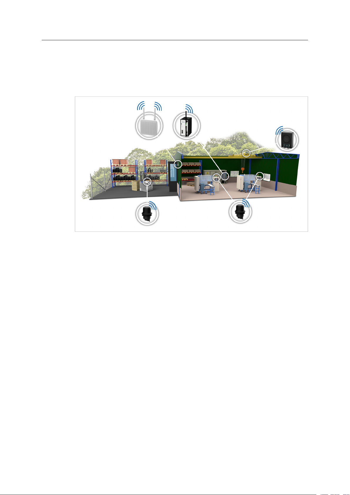
Anybus WLAN Access Point IP30 is an industrial grade IEEE802.11 a/b/g/n dual-band wireless
infrastructure hub that can operate as a 2.4 GHz/5 GHz WLAN access point, client or wireless
bridge. It is designed to work seamlessly with other Anybus wireless devices to connect
machines to a wireless infrastructure.
Fig. 1 Wireless infrastructure example
Anybus WLAN Access Point IP30 has dual Ethernet ports operating in switched mode to allow
daisy-chaining and redundant connectivity, and multiple digital inputs/outputs that can be used
to monitor and trigger external events. It has dual power supply inputs for redundancy and a
built-in alarm function on power failure.
The access point supports IEEE 802.1x to enhance security for WLAN connections. The
access point will act as authenticator and the clients will get authentication from a RADIUS
(Remote Authentication Dial In User Service) server.
Anybus®WLAN Access Point IP30 User Manual SCM-1202-093-EN 1.0
Installation 5 (30)
3 Installation
Caution
This equipment emits RF energy in the ISM (Industrial, Scientific, Medical) band.
Make sure that all medical devices used in proximity to this device meet
appropriate susceptibility specifications for this type of RF energy.
This product contains parts that can be damaged by electrostatic discharge (ESD).
Use ESD prevention measures to avoid damage.
Make sure that you have all the necessary information about the capabilities and restrictions of
your local network environment before installation.
For optimal reception, wireless devices require a zone between them clear of objects that could
otherwise obstruct or reflect the signal. A minimum distance of 50 cm between the devices
should also be observed to avoid interference.
The Anybus WLAN Access Point IP30 can be mounted on a standard DIN rail or screwmounted directly onto a flat surface using the included wall mounting kit.
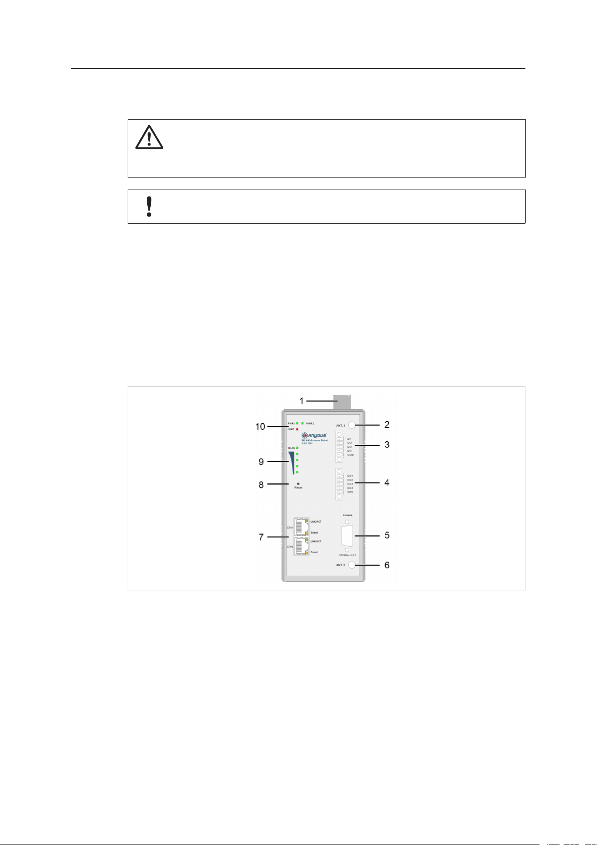
3.1 Overview
Fig. 2 Overview
1 Power connector
2, 6 Antenna connectors
3 Digital inputs
4 Digital outputs
5
7 Ethernet connectors
8 Reset button
9 WLAN signal LEDs
10 Status LEDs
Console connector (not used)
Anybus
®
WLAN Access Point IP30 User Manual SCM-1202-093-EN 1.0

Installation 6 (30)
3.2 Connectors
3.2.1 Power Connector
Fig. 3 Top view
Connecting power with reverse polarity or using the wrong type of power supply
may damage the equipment. Make sure that the power supply is correctly
connected and of the recommended type.
The power connector consists of a 6-pin terminal block located on the top of the unit. The unit
can be supplied with power from two independent 12–48 VDC power sources for redundancy
using the inputs PWR-1 and PWR-2.
See also Technical Data, p. 28 regarding power supply requirements.
The power connector also includes a relay output, Fault, that can be used for triggering an
alarm in case of power failure (see the User Manual).
V1+ Power Input 1 +
V1- Power Input 1 -
V2+ Power Input 2 +
V2- Power Input 2 -
Fault Relay output, NO, max 1 A @ 24 V
Chassis ground
Anybus
®
WLAN Access Point IP30 User Manual SCM-1202-093-EN 1.0

Installation 7 (30)
3.2.2 Digital In/Out Connectors
Anybus WLAN Access Point IP30 has 4 digital inputs and 4 digital outputs that can be used for
monitoring and controlling purposes. See the description of the DIDO settings in the User
Manual for more information.
Digital Inputs
Pin Function
DI1 Direct input 1
DI2 Direct input 2
DI3 Direct input 3
DI4 Direct input 4
COM Common signal ground
Digital Outputs
Pin Function
DO1 Direct output 1
DO2 Direct output 2
DO3 Direct output 3
DO4 Direct output 4
GND Common signal ground
3.2.3 Ethernet Connectors
Anybus WLAN Access Point IP30 has two switched Ethernet ports with RJ45 type connectors
that are labeled ETH1 and ETH2.
Pin Function
1 TD+
2 TD3 RD+
4, 5, 7, 8 (reserved)
6 RD-
Anybus
®
WLAN Access Point IP30 User Manual SCM-1202-093-EN 1.0
Installation 8 (30)
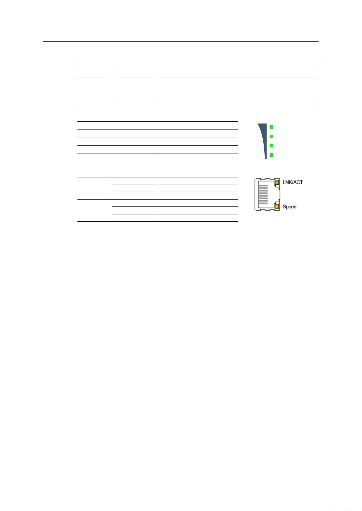
3.3 LED Indicators
PWR1
PWR2 Green
FAULT Red General error
WLAN
Green
Off No WLAN link
Green WLAN link established
Green, flashing WLAN traffic
Power input 1
Power input 2
4 LEDs
2–3 LEDs Adequate WLAN signal
1 LED Weak WLAN signal
All unlit No WLAN signal
Strong WLAN signal
ETH1/ETH2 LEDs
Off No link
LNK/ACT
Speed
Green Link established
Green, flashing Ethernet traffic
Off No traffic
Orange 10/1000 Mbit/s
Green 100 Mbit/s
Anybus
®
WLAN Access Point IP30 User Manual SCM-1202-093-EN 1.0
 Loading...