

Page 1
Module Name Project No
Subject Approved by Page
Appl. note for ABC-PDP and Anybus-X Serial server Martin Falkman 1(10)
AB7000 & AB7701
Document ID Revision
- 1.00
Issued by Date
Patrik Lansdorf 2005-11-28
ABC-PDP and ABX-Serial server
Application Note
Rev. 1.00
About this application note:
This application note describes how to configure an
Anybus-X Serial Server together with an ABC-PDP
module. The contents describe step by step how to
setup the system.
This document assumes that the reader is familiar with
industrial communication, Profibus networks and HMS
Gateways.
Page 2

Module Name Project No
AB7000 & AB7701
Document ID Revision
- 1.00
Issued by Date
Subject Approved by Page
Patrik Lansdorf 2005-11-28
Appl. note for ABC-PDP and Anybus-X Serial server Martin Falkman 2(10)
History
Revision Date Description Responsible
1.00 2005-11-28 Created Patrik Lansdorf
Page 3

Module Name Project No
AB7000 & AB7701
Document ID Revision
- 1.00
Issued by Date
Subject Approved by Page
Patrik Lansdorf 2005-11-28
Appl. note for ABC-PDP and Anybus-X Serial server Martin Falkman 3(10)
Contents
1 Requirements............................................................................................................................................4
2 System configuration................................................................................................................................5
2.1 Software configuration.......................................................................................................................6
2.1.1 Configuring the IP address on the Serial server.........................................................................6
2.1.2 Configuring the Serial/IP............................................................................................................7
2.1.3 Web functions.............................................................................................................................8
3 Testing.......................................................................................................................................................9
4 List of Figures and Tables .....................................................................................................................10
Page 4
Module Name Project No
AB7000 & AB7701
Document ID Revision
- 1.00
Issued by Date
Subject Approved by Page
Patrik Lansdorf 2005-11-28
Appl. note for ABC-PDP and Anybus-X Serial server Martin Falkman 4(10)
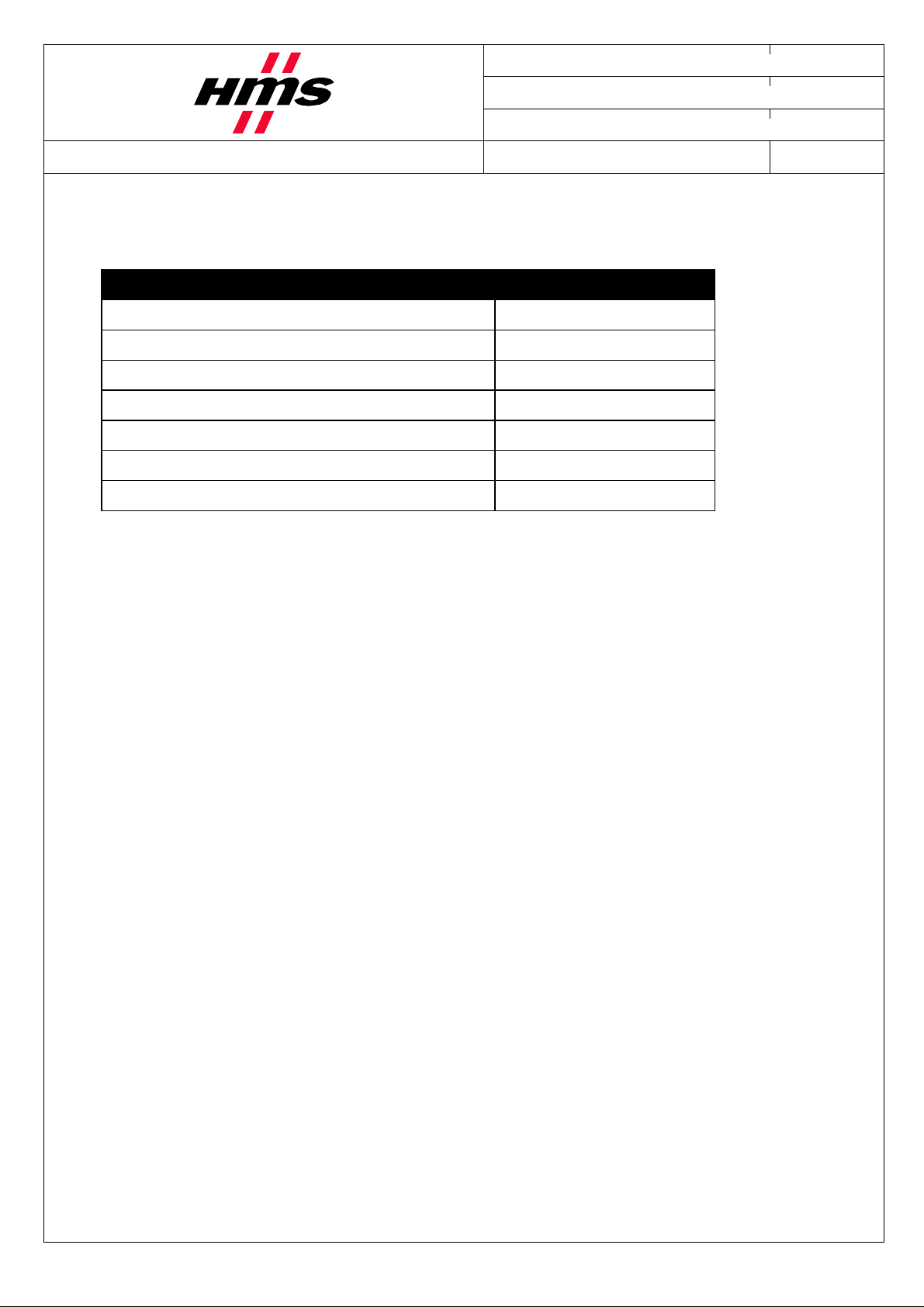
1 Requirements
Description Name / Type
Anybus Communicator for Profibus AB7000 / ABC-PDP
Anybus-X Serial server AB7701
Power supply 24V DC N.a.
Configuration cable for Anybus Communicator 017620
Serial/IP Com port redirection software 4.2.4 or later
Anybus IPConfig utility 1.1 or later
ABC config Tool 2.14 or later
Page 5
Module Name Project No
AB7000 & AB7701
Document ID Revision
- 1.00
Issued by Date
Subject Approved by Page
Patrik Lansdorf 2005-11-28
Appl. note for ABC-PDP and Anybus-X Serial server Martin Falkman 5(10)
2 System configuration
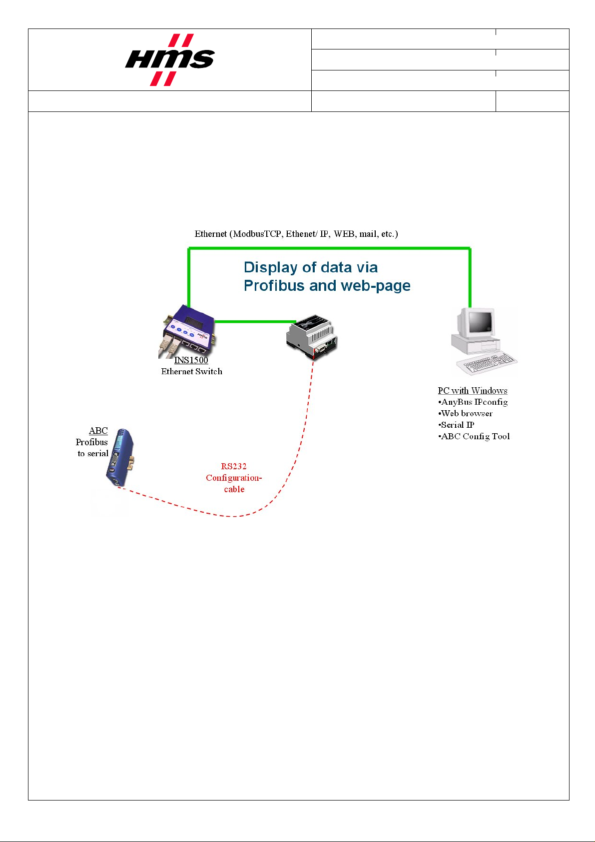
Below you find an overview of the system configuration that is described in this document.
Other devices may be attached to the Serial server, but since the scope of this application note is to use
one Anybus Communicator, only the configuration below will be explained.
Figure 1. Hardware connection overview
In this application it will be possible to download a configuration to the Anybus Communicator and change
some settings on the Serial server via the web interface or the Serial/IP Control Panel.
Page 6
Module Name Project No
AB7000 & AB7701
Document ID Revision
- 1.00
Issued by Date
Subject Approved by Page
Patrik Lansdorf 2005-11-28
Appl. note for ABC-PDP and Anybus-X Serial server Martin Falkman 6(10)
2.1 Software configuration
2.1.1 Configuring the IP address on the Serial server
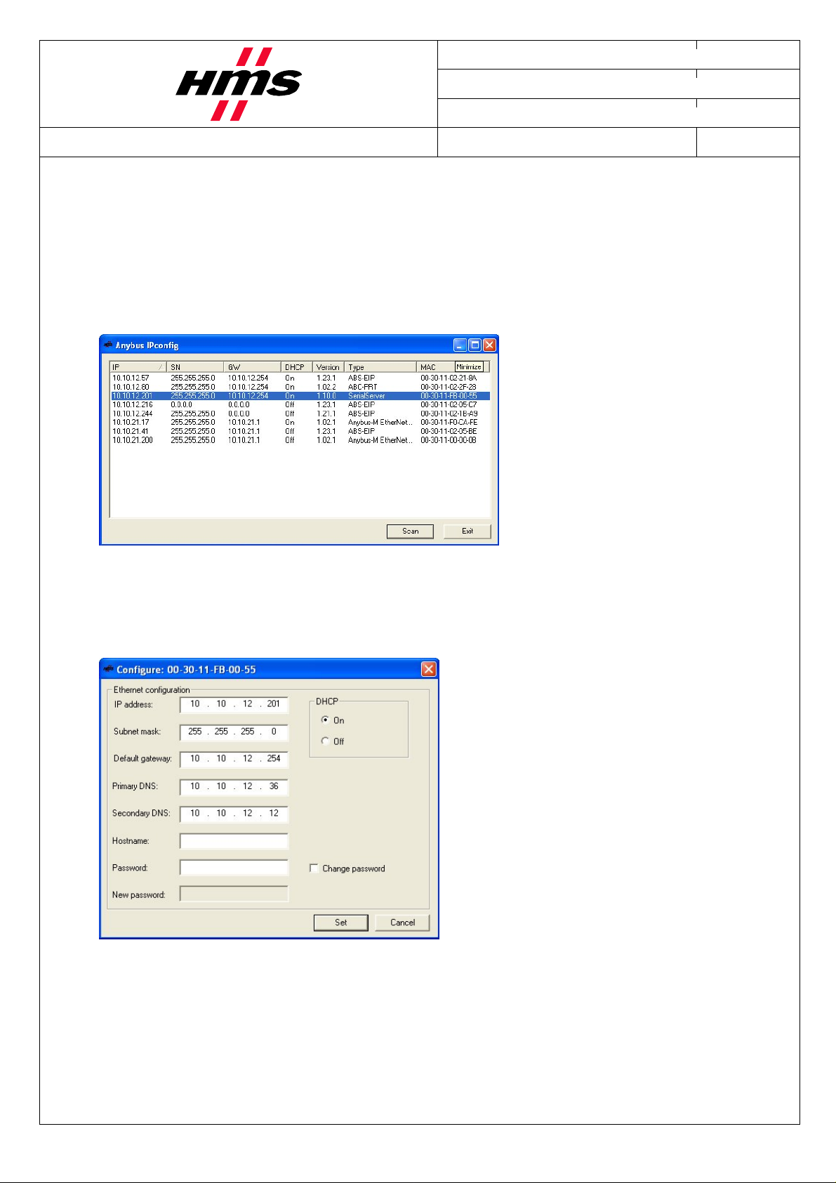
After installing the Anybus IPconfig software and connecting the Serial Server to the network, it should be
possible to see the module in the Anybus IPconfig tool, as shown below.
Figure 2. IPconfig
To change IP address and other settings on the module, double-click on the Serial server in the list.
The following window should appear.
Figure 3. Configure
Make the desired settings and press Set.
Page 7
Module Name Project No
AB7000 & AB7701
Document ID Revision
- 1.00
Issued by Date
Subject Approved by Page
Patrik Lansdorf 2005-11-28
Appl. note for ABC-PDP and Anybus-X Serial server Martin Falkman 7(10)
2.1.2 Configuring the Serial/IP
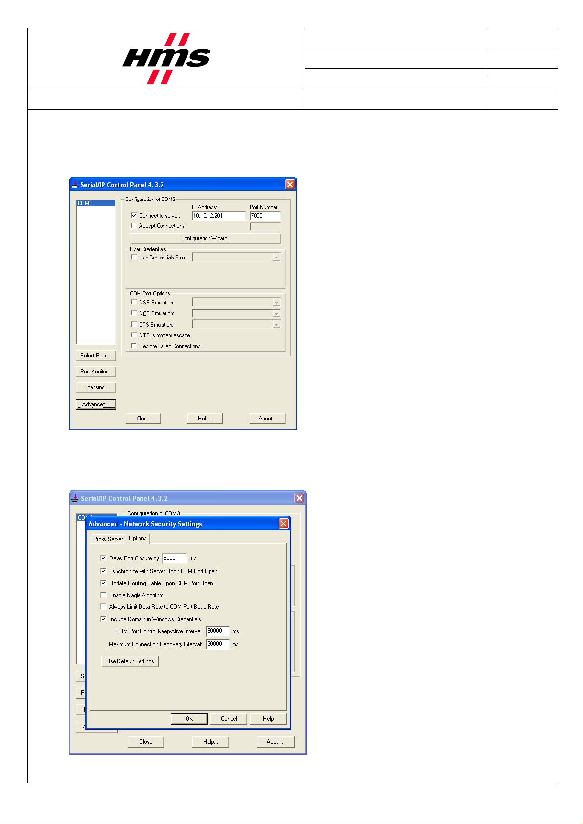
After installing the software Serial_IP_Anybus-X_424b.exe, the following window will appear.
Select which com. port to use, enter IP Address and Port number.
Figure 4. Serial/IP Control Panel
Under the Advanced button there are further settings to be made.
Figure 5. Serial/IP Control Panel
Page 8
Module Name Project No
AB7000 & AB7701
Document ID Revision
- 1.00
Issued by Date
Subject Approved by Page
Patrik Lansdorf 2005-11-28
Appl. note for ABC-PDP and Anybus-X Serial server Martin Falkman 8(10)
The Nagle Algorithm has to be disabled, in order for the Serial Server to be able to work properly together
with the Anybus Communicator.
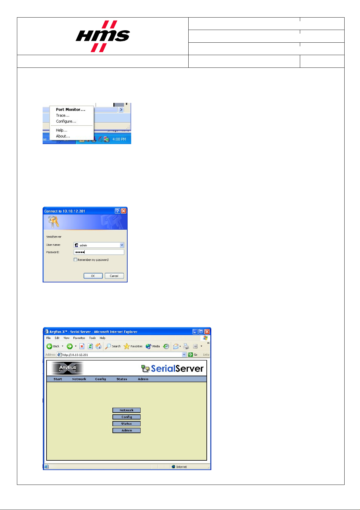
The settings of the Serial IP can always be accessed by right clicking on the Serial/IP, as shown below.
Figure 6 Serial/IP Properties
2.1.3 Web functions
The Serial Server can be accessed from the web. Simply type in the configured IP address in the address bar.
The default Username and Password is admin.
Figure 7. Log in
The settings that can be altered in the web interface are the same as in the Ipconfig tool, with the addition
that port number can also be modified under the Config button.
Figure 8. Serial server web interface
Page 9
Module Name Project No
AB7000 & AB7701
Document ID Revision
- 1.00
Issued by Date
Subject Approved by Page
Patrik Lansdorf 2005-11-28
Appl. note for ABC-PDP and Anybus-X Serial server Martin Falkman 9(10)
3 Testing
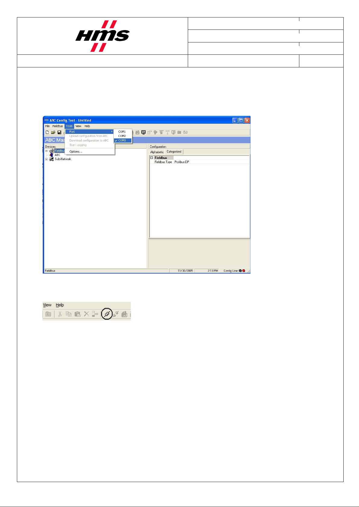
Connect the Anybus Communicator to the Serial server with the configuration cable. Start up the ABC
Config Tool and cancel the use of the wizard. Select which communication port to use, as shown in the
picture below.
Figure 9. Communication port selection
Press thereafter on the connect button, shown in the picture below.
Figure 10. Connect
It should now be possible to use all functions in the Anybus config Tool as if connected directly to the
Anybus Communicator via the standard communication port.
Page 10

Module Name Project No
AB7000 & AB7701
Document ID Revision
- 1.00
Issued by Date
Subject Approved by Page
Patrik Lansdorf 2005-11-28
Appl. note for ABC-PDP and Anybus-X Serial server Martin Falkman 10(10)
More information about the network and products
The latest manuals, software and GSD file can be found on the HMS homepage: www.anybus.com
4 List of Figures and Tables
Figure 1. Hardware connection overview .........................................................................................................5
Figure 2. IPconfig...............................................................................................................................................6
Figure 3. Configure ............................................................................................................................................6
Figure 4. Serial/IP Control Panel ......................................................................................................................7
Figure 5. Serial/IP Control Panel ......................................................................................................................7
Figure 6 Serial/IP Properties .............................................................................................................................8
Figure 6. Log in.................................................................................................................................................8
Figure 7. Serial server web interface.................................................................................................................8
Figure 9. Communication port selection...........................................................................................................9
Figure 10. Connect............................................................................................................................................9
 Loading...