

Page 1
Hardware Manual / Software Manual
T100 Development Kit
Manual
Page 2

HMS Technology Center Ravensburg GmbH
Helmut-Vetter-Straße 2
88213 Ravensburg
Germany
Tel.: +49 751 56146-0
Fax: +49 751 56146-29
Internet: www.hms-networks.de
E-Mail: info-ravensburg@hms-networks.de
Support
In case of unsolvable problems with this product please contact HMS in
written form by:
Fax: +49 751 56146-29
E-Mail: support@ixxat.de
Further international support contacts can be found on our webpage
www.ixxat.com/support
Copyright
Duplication (copying, printing, microfilm or other forms) and the electronic
distribution of this document is only allowed with explicit permission of
HMS Technology Center Ravensburg GmbH. HMS Technology Center
Ravensburg GmbH reserves the right to change technical data without
prior announcement. The general business conditions and the regulations
of the license agreement do apply. All rights are reserved.
Registered trademarks
All trademarks mentioned in this document and where applicable third
party registered are absolutely subject to the conditions of each valid
label right and the rights of particular registered proprietor. The absence
of identification of a trademark does not automatically mean that it is not
protected by trademark law.
Document number: 4.01.0300.20100
Version: 1.6 Release
Page 3

Document history
Date
Version
Change
Editor
24.11.17
1.6
Support of IXXAT Safe T100/FSoE
added. Dynamic non-safe ADI
configuration removed. Flow charts (CIP
Safety IP Address) updated. Cycle Time
attribute described for the first time.
K. Angele
Page 4

Content
Copyright HMS TC Ravensburg GmbH
3
T100 Development Kit Manual,
Version 1.6
Document history .................................................................................. 5
Referenced documents ........................................................................ 5
Abbreviations ........................................................................................ 6
1 Overview ......................................................................................... 7
1.1 Anybus CompactCom objects ............................................. 10
1.2 Functional Safety Object ...................................................... 11
2 Power Supply connection ........................................................... 12
3 Address Switches ........................................................................ 13
3.1 PROFIsafe F-Address ........................................................... 13
3.2 CIP Safety IP Address ........................................................... 14
3.3 FSoE Slave Address ............................................................. 17
4 Enable the Safety module ........................................................... 18
4.1 Communication Cycle Time ................................................. 19
5 Non-safe process data handling ................................................. 20
5.1 PROFINET ............................................................................. 21
5.2 EtherNet/IP ............................................................................ 21
5.3 EtherCAT ............................................................................... 21
5.4 Non-safe input data .............................................................. 22
5.5 Non-safe output data ............................................................ 24
6 Network Configuration ................................................................ 26
6.1 PROFINET (GSDML) ............................................................. 26
6.2 EtherNet/IP ............................................................................ 26
6.2.1 Electronic Data Sheet (EDS) ................................................. 26
6.2.2 Configuration Data String ....................................................... 26
6.2.3 PLC Configuration in RSLogix Designer (Studio 5000) ......... 27
6.2.3.1 Device Identity and Connections .............................. 27
6.2.3.2 SCID (Safety Configuration Identifier) ...................... 28
6.2.3.3 Safety Network Number / TUNID ............................. 29
6.3 EtherCAT (ESI) ...................................................................... 29
7 Fault reset button ......................................................................... 30
7.1 Manual Fault Reset ............................................................... 30
7.2 Automatic Fault Reset .......................................................... 30
8 Reset button ................................................................................. 31
Page 5

Content
Copyright HMS TC Ravensburg GmbH
4
T100 Development Kit Manual,
Version 1.6
9 LED indicators.............................................................................. 32
9.1 PROFIsafe ............................................................................. 32
9.2 CIP Safety .............................................................................. 33
9.3 FSoE ...................................................................................... 33
10 Safety I/O Connectors .................................................................. 34
11 Other components ....................................................................... 35
11.1 Jumper ................................................................................... 35
11.2 Switch S1 ............................................................................... 35
11.3 Pin Header JP18 .................................................................... 35
11.4 JTAG Connector ................................................................... 35
11.5 RS232 connector JP7 ........................................................... 35
12 Web page ...................................................................................... 36
13 Wiring Diagram ............................................................................ 37
14 Product Support and Conformity ............................................... 43
14.1 Support .................................................................................. 43
14.2 Returning hardware .............................................................. 43
14.3 Information on EMC .............................................................. 43
14.4 EC Declaration of Conformity .............................................. 44
Appendix A – ADI Configuration ................................ ........................ 45
ADI 1 ............................................................................................. 45
ADI 2 ............................................................................................. 46
Appendix B – Firmware Upgrade ....................................................... 47
Development Kit board ................................................................ 47
Anybus CompactCom .................................................................. 47
T100 .............................................................................................. 47
Page 6

Referenced documents
Copyright HMS TC Ravensburg GmbH
5
T100 Development Kit Manual,
Version 1.6
Referenced documents
[1] Safety Manual for IXXAT Safe T100
[2] Network Guide Anybus CompactCom 40 PROFINET IRT,
Doc. Id. SCM-1202-023 Rev. 1.4
[3] Network Guide Anybus CompactCom 40 EtherNet/IP,
Doc. Id. SCM-1202-031 Rev. 1.1
[4] Network Guide Anybus Compact Com 40 EtherCAT,
Doc. Id. SCM-1202-034 Rev. 1.4
Page 7

Abbreviations
Copyright HMS TC Ravensburg GmbH
6
T100 Development Kit Manual,
Version 1.6
Abbreviations
ABCC Anybus CompactCom – Network communication module with a
protocol independent software interface.
ADI Application Data Instances – Instance of an application input or
output module which can be used to exchange data e.g. with a PLC.
CB Carrier Board – Printed circuit board of the DevKit that is the mounting
base for the T100 and the ABCC
DevKit Development Kit – Abbreviation for this product.
EDS Electronic Data Sheet – ASCII text file that describes the
characteristics of a CIP device and is used by software tools for
device and network configuration.
ESI EtherCAT Slave Information (EtherCAT Devices Description) – A XML
file that describes the characteristic of an EtherCAT device. The file is
used by software tools for device and network configuration.
GSDML General Station Description Markup Language – In an XML based
language this file describes the characteristics of a PROFINET
device.
MDP Modular Device Profile - The Modular Device Profile defines a
modeling of structures within in a device. Mainly the object dictionary
structure and corresponding behavior of the entries is defined by the
MDP. The intention is to provide an easy way for master and
configuration tools to handle the devices.
PLC Programmable Logic Controller – A programmable electronic device
used in industrial automation to provide logic and sequencing controls
for machinery.
SCCRC Safety Configuration CRC – CRC that covers the device configuration
data.
SCTS Safety Configuration Time Stamp – Safety related signature that
identifies the revision of the device configuration.
SCID Safety Configuration Identifier – Combination of the SCCRC and the
SCTS used to uniquely identify a configuration.
TUNID Target Unique Network Identifier – Uniquely identifies a device in a
CIP Safety Network.
UTC Coordinated Universal Time – Base for the definition of the SCTS and
the Safety Network Number in the TUNID.
Page 8
Overview
Copyright HMS TC Ravensburg GmbH
7
T100 Development Kit Manual,
Version 1.6
1 Overview
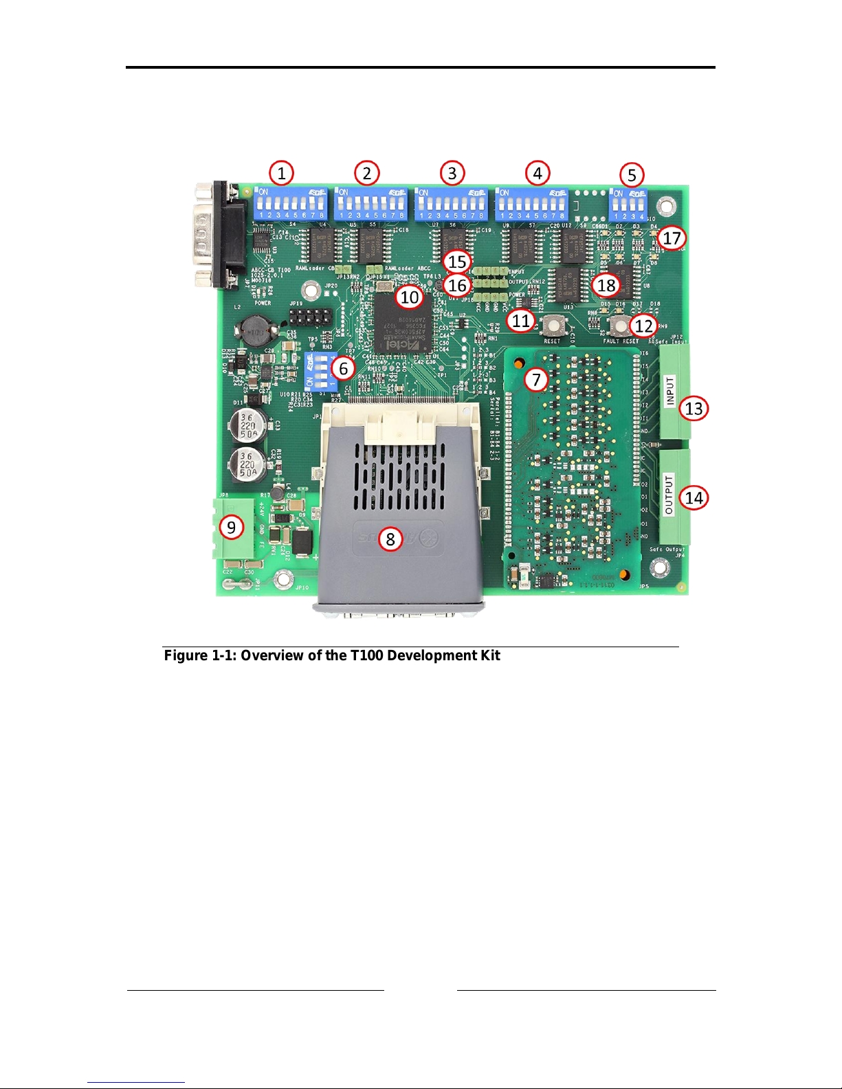
Figure 1-1: Overview of the T100 Development Kit
Page 9
Overview
Copyright HMS TC Ravensburg GmbH
8
T100 Development Kit Manual,
Version 1.6
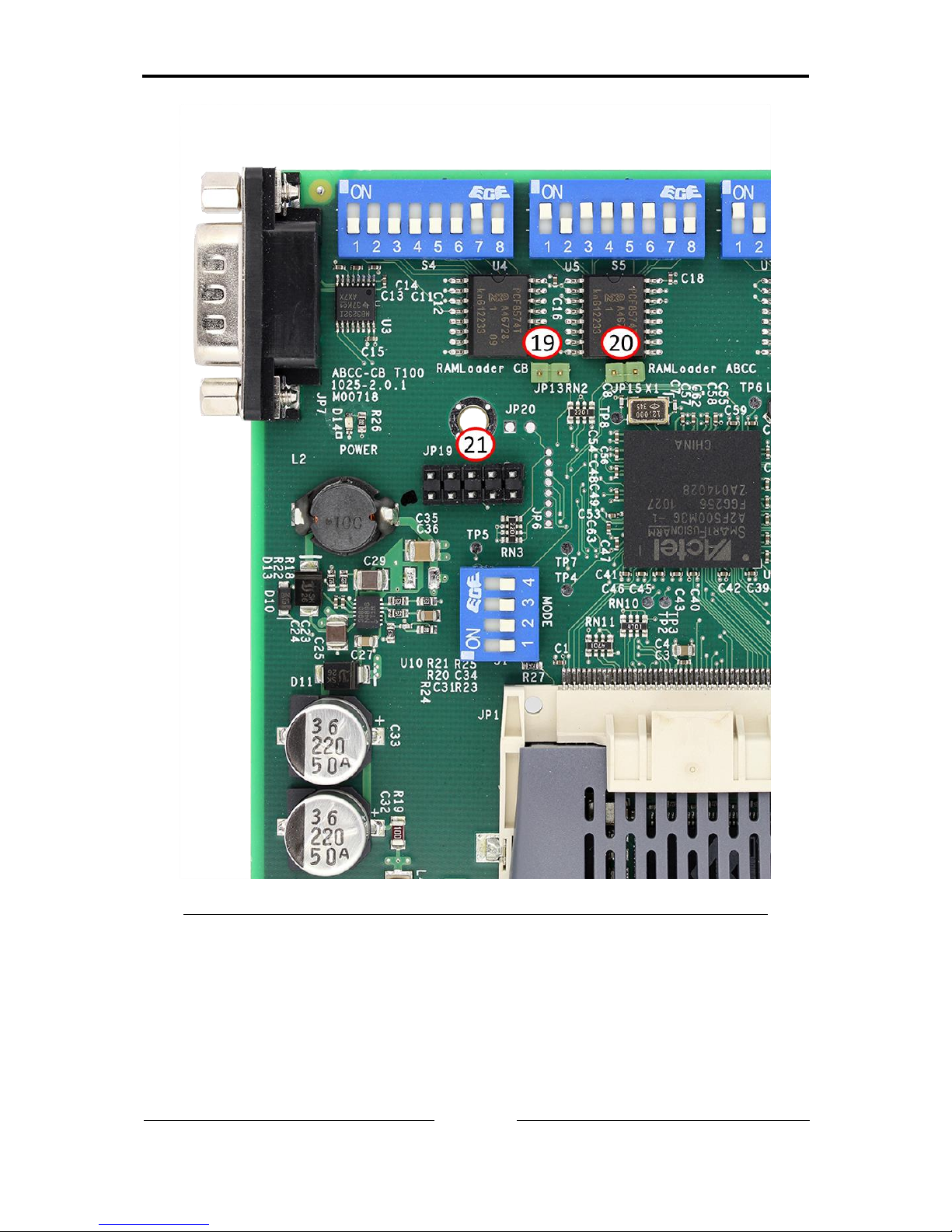
Figure 1-2: Detailed view of the T100 Development Kit
Page 10

Overview
Copyright HMS TC Ravensburg GmbH
9
T100 Development Kit Manual,
Version 1.6
Number
Name
1
Switch S4
2
Switch S5
3
Switch S6
4
Switch S7
5
Switch S10
6
Switch S1
7
Safe T100
8
Anybus CompactCom
9
24V DC Input
10
Host Processor
11
Board Reset
12
Fault Reset
13
Safe Inputs
14
Safe Outputs
15
Non-Safe Inputs JP16
16
Non-Safe Outputs JP17
17
Status LEDs D1-D8
18
User LEDs D15-D16
19
RAMloader CB Jumper 13
20
RAMloader ABCC Jumper 15
21
JTAG Interface JP19
This manual describes the basic functionality and how to use an Anybus
CompactCom (ABCC) with an IXXAT Safe T100/PS, T100/CS or T100/FSoE
module attached. It also describes how the safe and non-safe functionality of
the Development Kit is implemented and used based on a simple I/O demo
application.
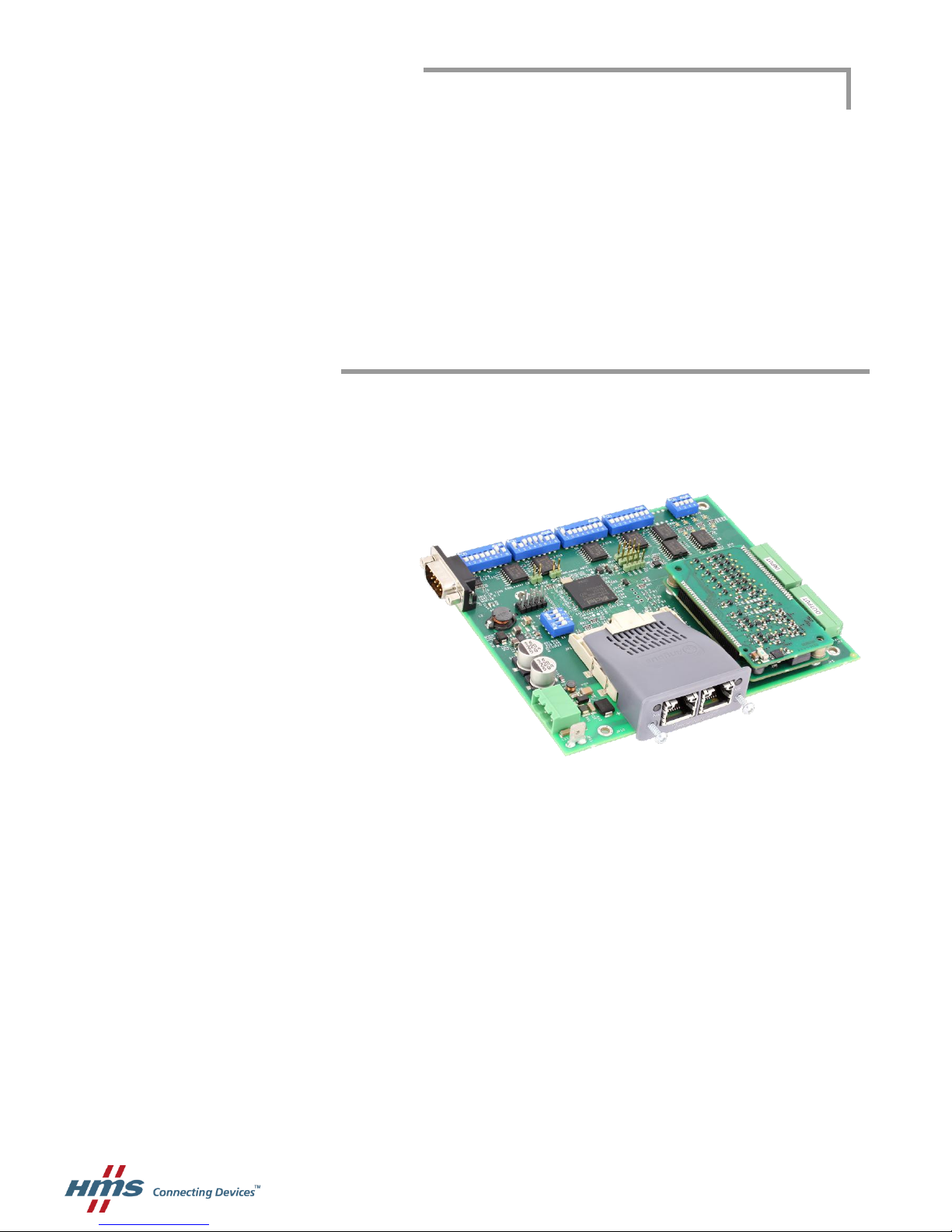
The Development Kit consists of a carrier board (CB) hosting an Anybus
CompactCom, an IXXAT Safe T100/PS, T100/CS or T100/FSoE and a host
application microprocessor. For demonstration purposes the host application
microprocessor runs a simple (non-safe) I/O demo. This demo software is also
initializing the IXXAT Safe T100 module via the ABCC object interface which is
described in more details within this manual.
Page 11
Overview
Copyright HMS TC Ravensburg GmbH
10
T100 Development Kit Manual,
Version 1.6
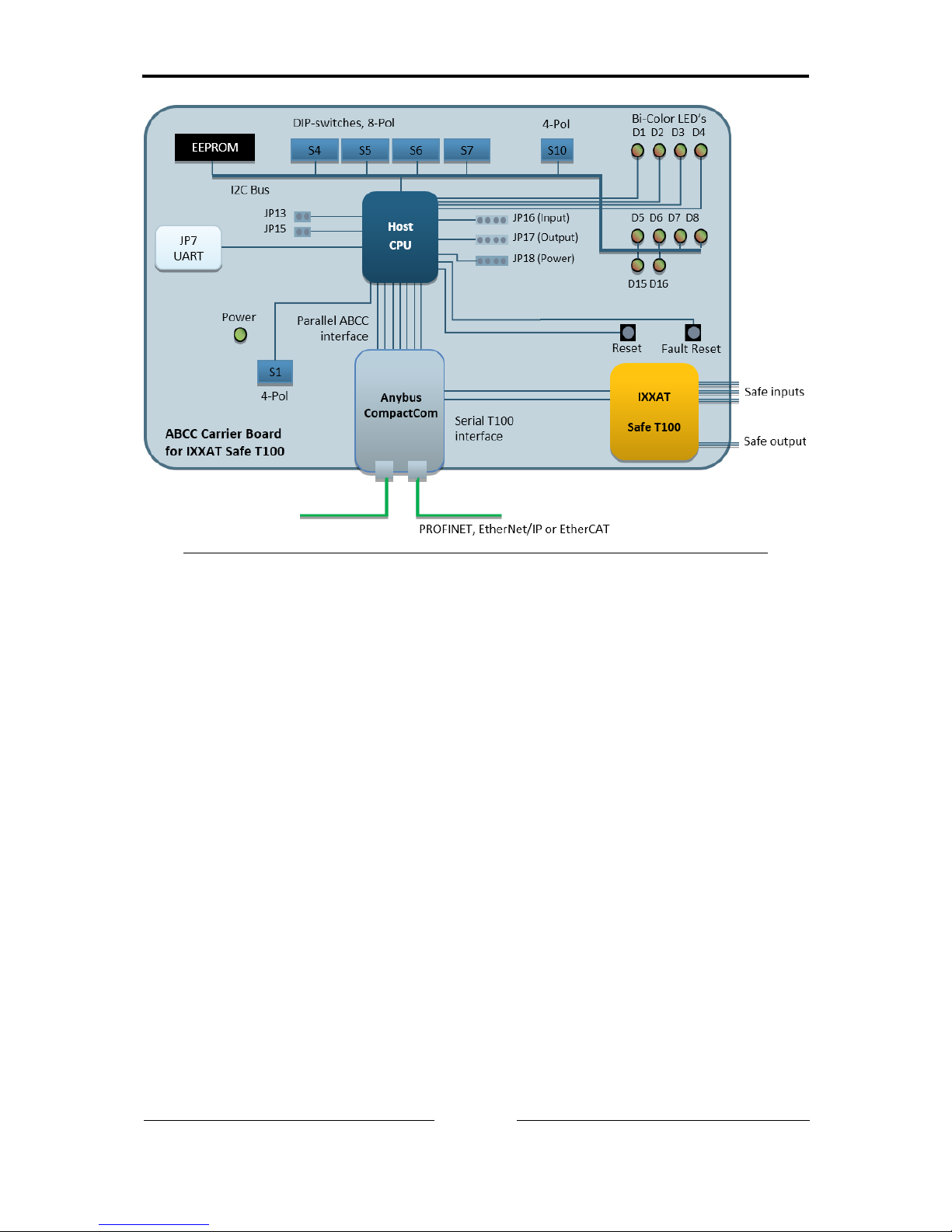
Figure 1-3: Development Kit block diagram
For detailed information about the IXXAT Safe T100 module please refer to
the Safety Manual [1].
In the following sections the Anybus CompactCom objects and host
application objects containing information related to functional safety are
described. Please consult the Anybus CompactCom 40 Network Guide ([2] for
PROFINET, [3] for EtherNet/IP, [4] for EtherCAT) for detailed information
regarding these objects.
1.1 Anybus CompactCom objects
The Anybus CompactCom contains the main control and configuration objects
which are necessary to activate and configure the IXXAT Safe T100 operation.
These objects can be accessed via the following object references (indices):
Functional Safety Module Object (11h)
Network Configuration Object (04h)
Page 12

Overview
Copyright HMS TC Ravensburg GmbH
11
T100 Development Kit Manual,
Version 1.6
1.2 Functional Safety Object
The Functional Safety Object (E8h) is implemented in the host application
processor. It contains information which is relevant for the host application
process.
Page 13

Power Supply connection
Copyright HMS TC Ravensburg GmbH
12
T100 Development Kit Manual,
Version 1.6
2 Power Supply connection
JP8: 24V DC Input (-15% + 20% according to IEC 61131-2)
and Protective Earth
JP11: Protective Earth
Figure 2-1: Power and Protective Earth connectors
Page 14
Address Switches
Copyright HMS TC Ravensburg GmbH
13
T100 Development Kit Manual,
Version 1.6
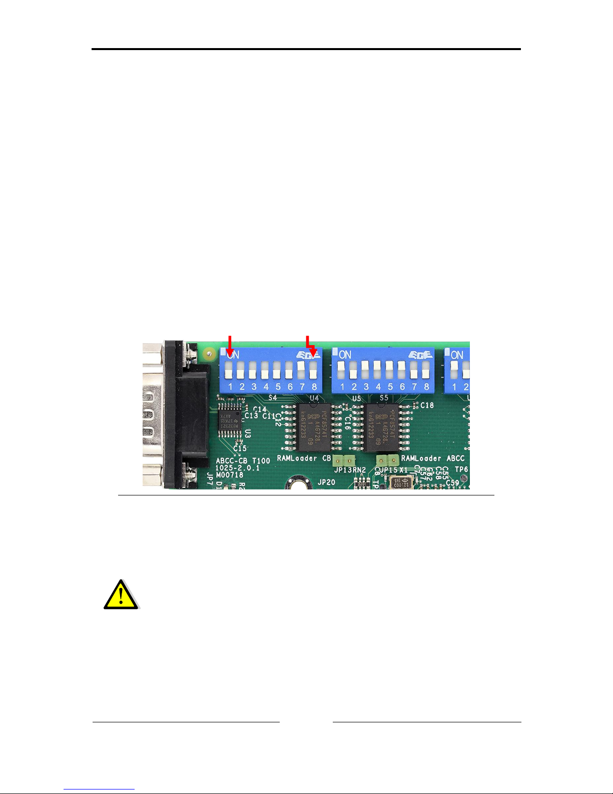
3 Address Switches
3.1 PROFIsafe F-Address
The F-address is the PROFIsafe address on the network which must be
configured from the host application before “Setup complete” of the Anybus
CompactCom module state machine. The F-address is located in instance #21
“F-Address” of the Network Configuration object in the Anybus CompactCom
module and must match the F-address configured in the PLC for the system to
work.
Switches S4 and S5 are used by the Development Kit host application to read
in the value which is then written to the F-Address value attribute. The FAddress is read considering the two DIP-switches as two bytes with the MSB
given by S4 and the LSB given by S5. If the switch lever is down it is
interpreted as OFF/0, if it is up it is interpreted as 1/ON. The range for a valid
F-Address is between 1 and 65534.
Figure 3-1: Switches S4 and S5 to set the PROFIsafe F-Address
Example: The switches in the figure have the F-address 700 – or 00000010
10111100 in binary – configured.
If the F-address value changes (in this case, someone alters S4
and/or S5) during runtime, the new value must be sent from the
host application to the Anybus CompactCom. As the value is only
sent during startup to the IXXAT Safe T100 it will be used after the
next restart of the system.
MSB
LSB
Highest bit
Lowest bit
Page 15
Address Switches
Copyright HMS TC Ravensburg GmbH
14
T100 Development Kit Manual,
Version 1.6
3.2 CIP Safety IP Address
CIP Safety devices can optionally determine their IP-address by means of
hardware switches. In the Development Kit host application Switch S5 is used
for this purpose.
Setting Switch S5 to a value between 1 and 254 indicates that the IP address
of the device is determined by this switch (see Figure 3-2). The IP address of
the device is then set to 192.168.1.switch-value. The subnet mask is set to
255.255.255.0. The default gateway is set either to 192.168.1.1 or (to avoid
equality with the IP address) to 0.0.0.0 in case the switch is set to 1.
For switch settings 0 or 255 the IP address is determined by the Anybus
CompactCom module itself (e.g. DHCP, TCP/IP Object attribute, web server,
etc.).
Setting the IP address configuration is done by writing to the Network
Configuration Object (see [3] for details).
For CIP Safety compliant behavior it is necessary to read and evaluate the
switch value during initialization of the Anybus CompactCom module (before
setting the Anybus Object attribute Startup Complete) according to the
example shown in Figure 3-3, but also to continuously sample the switch value
and react on changes. An example for the ongoing switch value evaluation is
shown in Figure 3-4 (“IP Address Change via Switch”).
Additionally the Development Kit host application has to react if the IP address
of the device was changed by network services (e.g. via TCP/IP Object
attribute). An example how to implement this behavior is also shown in Figure
3-4 (“IP Address Change via Network”).
Figure 3-2: Switch S5 to set IP address of the device.
LSB
Highest bit
Lowest bit
Page 16

Address Switches
Copyright HMS TC Ravensburg GmbH
15
T100 Development Kit Manual,
Version 1.6
INIT==255 OR
INIT==0 ?
FALSE
TRUE
Power-On
DHCP Enabled ?
FALSE
TRUE
Read Switch S5
INIT = S5
Get DHCP Status
(Network Configuration Object 04h
DHCP (Inst#6, Attr#5)
Set IP Address to '1'
(Network Configuration Object 04h)
IP: 192.168.1.1 (Inst#3, Attr#5)
Subnet: 255.255.255.0 (Inst#4, Attr#5)
Gateway: 0.0.0.0 (Inst#5, Attr#5)
DHCP: Disabled (Inst#6, Attr#5)
Set IP Address to 'INIT'
(Network Configuration Object 04h)
IP: 192.168.1.INIT (Inst#3, Attr#5)
Subnet: 255.255.255.0 (Inst#4, Attr#5)
Gateway: 192.168.1.1 (Inst#5, Attr#5)
DHCP: Disabled (Inst#6, Attr#5)
INIT==1 ?
FALSE
TRUE
DeviceIpAddr =
192.168.1.INIT
DeviceIpAddr =
192.168.1.1
DeviceIpAddr =
Value
Get IP Address 'Value'
(Network Configuration Object 04h)
IP (Inst#3, Attr#5)
DeviceIpAddr =
0.0.0.0 (unassigned)
IP Settings valid and
used for communication
Use DHCP
Figure 3-3: Determination of the initial IP-address based on Switch S5
Page 17

Address Switches
Copyright HMS TC Ravensburg GmbH
16
T100 Development Kit Manual,
Version 1.6
INIT <> NEW ?
TRUE
Set IP Address to 'NEW'
(Network Configuration Object 04h)
IP: 192.168.1.NEW (Inst#3, Attr#5)
Gateway: 192.168.1.1 (Inst#5, Attr#5)
FALSE
NEW ==255 OR
NEW==0 ?
TRUE
Read Switch S5
NEW = S5
Loop
Set IP Address to 'NEW'
(Network Configuration Object 04h)
IP: 192.168.1.NEW (Inst#3, Attr#5)
Set IP Address to 'INIT'
(Network Configuration Object 04h)
IP: 192.168.1.INIT (Inst#3, Attr#5)
NEW==1 ?
FALSE
Set IP Address to '1'
(Network Configuration Object 04h)
IP: 192.168.1.1 (Inst#3, Attr#5)
Gateway: 0.0.0.0 (Inst#5, Attr#5)
TRUE
Get IP Address 'CfgIpAddr'
(Network Configuration Object 04h IP
(Inst#3, Attr#6)
FALSE
Set IP Address to 'DeviceIpAddr'
(Network Configuration Object 04h)
IP: SafetyIpAddr (Inst#3, Attr#5)
Set IP Address to 'CfgIpAddr'
(Network Configuration Object 04h)
IP: CfgIpAddr (Inst#3, Attr#5)
DeviceIpAddr =
'CfgIpAddr'
IpAddrChangedEvt
TRUE
'DeviceIpAddr' ==
0.0.0.0
'CfgIpAddr' <>
'DeviceIpAddr'
TRUE
TRUE
FALSE
FALSE
FALSE
IP Address Change via Switch
IP Address Change via Network
Triggers 'Abort' request to
T100/CS
NEW IP address is used
after restet
Restore INIT IP address
Triggers 'Abort' request
to T100/CS
IP Address change request
during runtime
Restore IP address
IP assigned for the first
time e.g. by DHCP
Triggers 'Abort' request
to T100/CS
Flag set if Ethernet Host Object
(Instance 1, Attr. 16) is written
Figure 3-4: Cyclic check for IP Address changes
Page 18

Address Switches
Copyright HMS TC Ravensburg GmbH
17
T100 Development Kit Manual,
Version 1.6
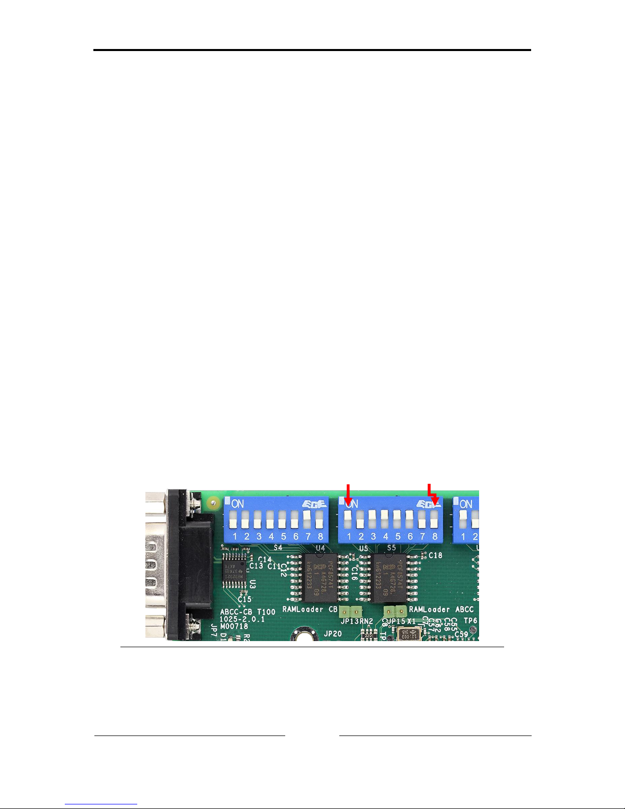
3.3 FSoE Slave Address
The FSoE Slave Address is a unique address inside the communication
system which is used to check whether a FSoE Slave is actually addressed.
The FSoE Slave Address must be configured from the host application before
“Setup complete” of the Anybus CompactCom module state machine. The
FSoE Slave Address is located in instance #21 “FSoE Address” of the Network
Configuration object in the Anybus CompactCom module.
Switches S4 and S5 are used by the Development Kit host application to read
in the value which is then written to the FSoE slave address value attribute.
The FSoE Slave Address is read considering the two DIP-switches as two
bytes with the MSB given by S4 and the LSB given by S5. If the switch lever is
down it is interpreted as OFF/0, if it is up it is interpreted as 1/ON. The range
for a valid FSoE Slave Address is between 1 and 65535.
Figure 3-5: Switches S4 and S5 to set the FSoE Slave Address
The FSoE Slave Address is only sent during startup to the IXXAT
Safe T100/FSoE. So changes in the FSoE Slave Address will only
take effect after the next restart of the Development Kit.
MSB
LSB
Highest bit
Lowest bit
Page 19

Enable the Safety module
Copyright HMS TC Ravensburg GmbH
18
T100 Development Kit Manual,
Version 1.6
4 Enable the Safety module
The host application must enable the safety module by implementing the
Functional Safety Object, and respond with TRUE when a request for the
value of the attribute “Safety enabled” is received during the startup sequence.
More information about the Functional Safety Object can be found in the
Anybus CompactCom PROFINET Network Guide (see [2]) respectively
Anybus CompactCom EtherNet/IP Network Guide (see [3]) respectively
Anybus CompactCom EtherCAT Network Guide (see [4]).
To enable the safety functionality of the IXXAT Safe T100 the host application
needs to respond to the Safety enabled attribute request.
- For PROFIsafe additionally the F-address must be set (see chapter 3.1).
- For CIP Safety additionally the Cycle Time attribute shall be
implemented (see chapter 4.1). Furthermore the host application can
assign the IP address (see chapter 3.2).
- For FSoE additionally the FSoE Slave Address must be set (see chapter
3.3).
All other functional safety related attributes shall be considered as non-safe
status information only.
Switch S6:1 is used by the Development Kit host application to decide if the
safety module shall be enabled or not.
Figure 4-1: Switch S6 with safety functionality enabled.
S6:1
Description
OFF
Safety functionality disabled. Value of DIP-switch has only effect
during start-up.
ON
Safety functionality enabled. Value of DIP-switch has only effect
during start-up.
S6:2 to S6:8 are used for internal tests and should stay in default
position OFF.
S6:1
Page 20

Enable the Safety module
Copyright HMS TC Ravensburg GmbH
19
T100 Development Kit Manual,
Version 1.6
4.1 Communication Cycle Time
The Cycle Time attribute (#4) configures the communication cycle time
between Anybus CompactCom and IXXAT Safe T100 in milliseconds.
For CIP Safety the host application needs to respond to the Cycle Time
attribute request with a value of 4ms.
When using PROFIsafe or FSoE there is no need to implement this attribute
because the expected value of 2ms is the default value used by Anybus
CompactCom.
Page 21

Non-safe process data handling
Copyright HMS TC Ravensburg GmbH
20
T100 Development Kit Manual,
Version 1.6
5 Non-safe process data handling
The Development Kit host application configures the Anybus CompactCom
with two Application Data Instances (ADIs) for development purposes, which
describe the data possible to read and write through the network. For the
functional safety module itself, no ADIs are needed. The configuration and
process data mapping of non-safe data of the ADIs can be configured by
switch S7.
The default behavior can be activated by setting S7:1 to ON and the rest of the
switch to OFF. The default behavior enables using of S10 and JP16 for input
data and D15, D16 and JP17 for output data. The exact usage and handling
will be described in the following chapters.
For information about how the ADIs are configured, see Appendix A.
Figure 5-1: Switch S7 to manage non-safe I/O data
S7:1
Description
OFF
Read process data received from the network is copied and sent as
write process data.
ON
Read process data and write process data is mapped.
S7:2 to S7:8 are reserved and should stay in default position OFF.
S7:1
Page 22

Non-safe process data handling
Copyright HMS TC Ravensburg GmbH
21
T100 Development Kit Manual,
Version 1.6
5.1 PROFINET
Figure 5-2: Physical structure of the control
The non-safe output data is assigned to the Module located in Slot 2, while the
non-safe input data is assigned to the Module located in Slot 3.
5.2 EtherNet/IP
Input data is mapped to assembly instance 100 and outputs are mapped to
instance 150. These assembly instances can be used as connection points for
Class 1 connections (Exclusive-Owner / Listen-Only / Input-Only).
Assembly Instance
Description
100
Non-safe input data
103
Heartbeat, Input-Only
104
Heartbeat, Listen-Only
106
Heartbeat, Input-Only Extended
107
Heartbeat, Listen-Only Extended
150
Non-safe output data
5.3 EtherCAT
Figure 5-3: MDP structure of the Device
ABCC
-
ECT
IXXAT
Safe
T100
Slot 1
Output/
Input
Slot 2
…
ABCC
-
PRT
2 - ports
Slot 0
IXXAT
Safe
T100
Slot 1
Output
Module
1 Byte
Slot 2
Input
Module
1 Byte
Slot 3
…
Page 23

Non-safe process data handling
Copyright HMS TC Ravensburg GmbH
22
T100 Development Kit Manual,
Version 1.6
To use safe and non-safe data in parallel, the device implements the Modular
Device Profile (MDP) approach. Here the device is divided into several slots /
modules whereby each module (or function) can occupy several objects inside
its dedicated index area of the global object dictionary. Since the IXXAT Safe
T100/FSoE is always assigned to Slot 1, the non-safe input data and non-safe
output data module is assigned to Slot 2. The host application implements the
default index instance of 0x10, which leads to the following layout:
Slot
Index
PDO
Description
1
0x6000-0x600F
0x1600
Reserved for IXXAT Safe T100/FSoE
0x7000-0x700F
0x1A00
Reserved for IXXAT Safe T100/FSoE
2
0x6010
0x1601
Non-Safe input Data
0x6011-0x601F
---
Reserved
0x7010
0x1A01
Non-safe output data
0x7011-0x701F
---
Reserved
5.4 Non-safe input data
For modes where write process data (controller input) is mapped the value
may be set using the 4-pole DIP-switch S10 and the 4-pin header JP16. The 4
lower bits are represented by JP16 and the 4 higher bits are represented by
S10. The value is repeated for each byte in the write process data.
Bit 0Bit 3Bit 4Bit 7
S10 JP16
Figure 5-4: Input data represented by S10 and JP16
DIP-switch S10 and JP16 are low active. This means that when all switches of
DIP-switch S10 are off, they are interpreted as 1 and when they are on they
are interpreted as 0. Likewise all pins of pin header JP16 are pulled up
internally to 3.3V when not connected (interpreted as 1) and should be
connected to ground to be interpreted as 0.
For example if nothing is connected to JP16 and only S10:1 and S10:4 are on,
the input value is read as 6F, where 6 corresponds to S10 and F corresponds
to JP16.
Page 24

Non-safe process data handling
Copyright HMS TC Ravensburg GmbH
23
T100 Development Kit Manual,
Version 1.6
JP16 is directly connected to a PCF8574T I2C expander (NXP
Semiconductors) that is operated with 3.3V. For more information check the
datasheet of the PCF8574T.
Figure 5-5: Pin-header JP16 and Switch S10 for non-safe input data
Page 25

Non-safe process data handling
Copyright HMS TC Ravensburg GmbH
24
T100 Development Kit Manual,
Version 1.6
5.5 Non-safe output data
For modes where read process data (controller output) is mapped the value is
provided through the LEDs D15 and D16 and the 4-pin header JP17. The 4
lower bits are provided by JP17 and the 4 higher bits are displayed by LEDs
D15 and D16.
Bit 0Bit 3
JP17D16D15
Bit 4/5Bit 6/7
Figure 5-6: Output data represented by D15, D16 and JP17
Bit
LED
Color
4
D16
Green
5
Red
6
D15
Green
7
Red
Bit value 1 is displayed by the LED being off. So if the LEDs are turned on
green and red at once this shall be interpreted as output Bit sequence 0000, if
they are both green the value displayed is 0101 and if the LEDs are red the
value is 1010. If the LEDs are both off the displayed value is 1111.
JP17 is directly connected to a PCF8574T I2C expander (NXP
Semiconductors) that is operated with 3.3V. For more information check the
datasheet of the PCF8574T.
The non-safe outputs are cleared at the following events:
- Startup of the DevKit
- Provider status of the connected IO Controller is set to BAD
(PROFINET)
- RUN-bit is cleared in the 32-bit Run/Idle header of an Exclusive-Owner
connection (EtherNet/IP)
- Anybus CompactCom is in other state than ‘OPERATIONAL’
(EtherCAT)
- Connection loss
Page 26

Non-safe process data handling
Copyright HMS TC Ravensburg GmbH
25
T100 Development Kit Manual,
Version 1.6
Figure 5-7: Pin-header JP17 and LEDs D15 and D16 for non-safe output
data
Page 27

Network Configuration
Copyright HMS TC Ravensburg GmbH
26
T100 Development Kit Manual,
Version 1.6
6 Network Configuration
6.1 PROFINET (GSDML)
The provided Anybus CompactCom PROFINET GSDML-file is used for the
configuration of the IXXAT Safe T100/PS Development Kit in e.g. Siemens
Step7 or TIA configuration tool. The GSDML-file can be customized for the
end product according to the Anybus CompactCom PROFINET Network
Appendix (see [2]).
Special care has to be taken that the GSDML file part describing the safety
configuration objects are not altered or removed when editing the file.
6.2 EtherNet/IP
6.2.1 Electronic Data Sheet (EDS)
An EDS File is provided with the DevKit for the T100/CS. But depending on
the used PLC and toolchain it may not be possible to use this for configuration
purposes.
At the time this manual was written the EDS file is not usable for configuring
an IXXAT Safe T100/CS in Rockwell Studio 5000 Logix Designer. Thus the
settings for configuring the connections to the DevKit must be entered
manually.
6.2.2 Configuration Data String
The host application automatically configures the T100/CS during startup with
the default configuration data string. See [1] chapter 5.4.2 for details.
Page 28

Network Configuration
Copyright HMS TC Ravensburg GmbH
27
T100 Development Kit Manual,
Version 1.6
6.2.3 PLC Configuration in RSLogix Designer (Studio 5000)
6.2.3.1 Device Identity and Connections
The following figure shows an example for setting up connections for safe
inputs and safe outputs as well as non-safe inputs and outputs. The identity
information in the Module Parameters section may be subject to change (e.g.
Revision).
Figure 6-1: RSLogix Designer Identity and Connection Settings
Page 29

Network Configuration
Copyright HMS TC Ravensburg GmbH
28
T100 Development Kit Manual,
Version 1.6
6.2.3.2 SCID (Safety Configuration Identifier)
An SCID check can be activated on the Safety tab. When the Configuration
Signature check box is activated the PLC will send a Type 2a SafetyOpen
(SCID check active). Figure 6-3 shows the SCID of the DevKit default
configuration data string.
The value in the ID field represents the SCCRC whereas the SCTS can be
entered as a Date and Time value. Please note that the time is entered in the
local time zone of the PC and is being converted to UTC by RSLogix. The
example below was generated in the time zone CEST (UTC + 2h). Thus the
value actually transmitted is 36 000 000 ms (10:00:00.000).
Figure 6-2: RSLogix Designer Configuration Signature Settings
Page 30

Network Configuration
Copyright HMS TC Ravensburg GmbH
29
T100 Development Kit Manual,
Version 1.6
6.2.3.3 Safety Network Number / TUNID
After a download of the above configuration the connection of the PLC may fail
because the TUNID is not yet set (e.g. MS LED blinking red). While being
online click then the button with the 3 dots besides the Safety Network Number
(see Figure 6-1). In the windows that opens enter the Safety Network Number
(time-based or manual) and click “Set”. This will initiate a Propose_TUNID and
Apply_TUNID sequence to assign the TUNID.
Figure 6-3: Setting the TUNID in RSLogix Designer
6.3 EtherCAT (ESI)
An EDS-file is provided with the DevKit for the IXXAT Safe T100/FSoE. The
file is used for the device and network configuration and can be customized for
the end product.
Special care has to be taken that the ESI-file part describing the safety objects
is not altered or removed when editing the file.
Page 31

Fault reset button
Copyright HMS TC Ravensburg GmbH
30
T100 Development Kit Manual,
Version 1.6
7 Fault reset button
The IXXAT Safe T100/PS and the IXXAT Safe T100/FSoE supports only the
Manual Fault Reset mode whereas for the T100/CS this mode is the default
behavior, but is changeable to Automatic Fault Reset mode in the
configuration parameters.
7.1 Manual Fault Reset
When in the Manual Fault Reset mode, the IXXAT Safe T100 module has
entered the fail-state for any of the safe in- or outputs (e.g. due to failed
consistency or clock signal checks). In this case an error confirmation has to
be sent to recover from this error.
There are two ways of sending this error confirmation. The first one is via the
safety PLC and the second one is using the Fault Reset button operated by
the host application. When pressing the Fault Reset button while a fail-state is
present, the IXXAT Safe T100 module will reactivate the safe in- or output
again. If the error which caused the fail-state is still present, the safety module
will immediately enter the fail-state again. Otherwise the normal operation of
the safe in- and outputs is continued.
Figure 7-1: Fault reset button
When pressing the fault reset button, the “Error_Confirmation”-command in the
Functional Safety Module Object is requested from the Anybus CompactCom
module by the host application. As a consequence, the Anybus CompactCom
module sends an error confirmation command to the IXXAT Safe T100 module
which clears all pending channel-errors at once.
7.2 Automatic Fault Reset
This mode only exists for the IXXAT Safe T100/CS. In this mode the Fault
Reset button is inactive. Instead the fault reset behavior is determined by the
Safety Discrete Input Point Objects and Safety Discrete Output Point Objects.
This means that after the input or output returns to the inactive state and after
the corresponding error latch time has expired the fault is reset automatically
and the input or output enters the normal operation again.
Page 32

Reset button
Copyright HMS TC Ravensburg GmbH
31
T100 Development Kit Manual,
Version 1.6
8 Reset button
When pressing the reset button a complete reset of the whole Development Kit
board is performed including the Host processor, the Anybus CompactCom
and the T100.
Figure 8-1: Reset button
Page 33

LED indicators
Copyright HMS TC Ravensburg GmbH
32
T100 Development Kit Manual,
Version 1.6
9 LED indicators
Figure 9-1: LEDs D1 to D8
LEDs D1 and D2 show in red different error codes according to the following
table, where D1 corresponds to the highest bit and D4 to the lowest bit.
D1
D2
Description
OFF
OFF
No error
OFF
ON
ABCC error response or unknown/unsupported network
ON
OFF
Reserved
ON
ON
FATAL ABCC error
LEDs D3 and D4 are reserved for future use and are thus not relevant.
LEDs D5, D6, D7 and D8 reflect the value of the State attribute (#1) of the
Anybus CompactCom Functional Safety Module Object in green color. D5
corresponds to the highest bit and D8 to the lowest bit.
LEDs D5-D8 are all lit red if it is not possible to read out the State
from the Functional Safety Module Object.
9.1 PROFIsafe
The following table shows the possible patterns for the states of the T100/PS.
D5
D6
D7
D8
Description
OFF
OFF
OFF
OFF
Boot
OFF
OFF
OFF
ON
Selftest, Initialization
OFF
OFF
ON
OFF
Parametrization: Wait for F-Address
OFF
OFF
ON
ON
Run
OFF
ON
OFF
OFF
Parameterization:
Wait and Check F- and I-Parameter
ON
ON
ON
ON
Error / Safe State
Page 34

LED indicators
Copyright HMS TC Ravensburg GmbH
33
T100 Development Kit Manual,
Version 1.6
9.2 CIP Safety
The following table shows the possible patterns for the states of the T100/CS.
D5
D6
D7
D8
Description
OFF
OFF
OFF
OFF
BOOT
OFF
OFF
ON
OFF
WAIT_INIT
OFF
OFF
ON
ON
WAIT_TUNID
OFF
ON
OFF
OFF
WAIT_CONFIG
OFF
ON
OFF
ON
INVALID_CONFIG
OFF
ON
ON
OFF
IDLE
ON
OFF
OFF
OFF
EXEC_PROD_ONLY
ON
OFF
OFF
ON
EXEC_CONS_ONLY
ON
OFF
ON
OFF
EXEC_PROD_AND_CONS
ON
ON
OFF
OFF
WAIT_RESET
ON
ON
OFF
ON
INVALID_NODEID
ON
ON
ON
ON
FAILSAFE
9.3 FSoE
The following table shows the possible patterns for the states of the
T100/FSoE.
D5
D6
D7
D8
Description
OFF
OFF
OFF
OFF
BOOT
OFF
OFF
ON
OFF
WAIT_FOR_SADR
OFF
OFF
ON
ON
WAIT_FOR_INIT_LEAVE
OFF
ON
OFF
OFF
PRE_OPERATIONAL
OFF
ON
OFF
ON
SAFE_OPERATIONAL
OFF
ON
ON
ON
WAIT_FOR_FSOE_DATA
ON
OFF
OFF
OFF
FSOE_DATA
ON
ON
ON
ON
FAILSAFE
Page 35

Safety I/O Connectors
Copyright HMS TC Ravensburg GmbH
34
T100 Development Kit Manual,
Version 1.6
10 Safety I/O Connectors
The connectors for safe input and output are connected directly to the Safe
T100 module. See the safety manual [1] for detailed information.
Figure 10-1: Safe Inputs and Safe Outputs
Note that all IXXAT Safe T100 in- and outputs are 24V types.
Therefore they shall never be connected directly to the in- and
outputs of the Development Kit described in section 5.
Safe Input
Safe Output
Page 36

Other components
Copyright HMS TC Ravensburg GmbH
35
T100 Development Kit Manual,
Version 1.6
11 Other components
11.1 Jumper
JP13 is used for software upgrades by HMS. Closing JP13 during power-up
activates the serial bootloader of the host application microprocessor. See also
section 11.5.
JP15 is currently unused.
11.2 Switch S1
Switch S1 is currently unused.
11.3 Pin Header JP18
Pin 1 and 4 are connected to 3.3V. Pin 2 and 3 are connected to ground.
Figure 11-1: Pin header JP18
11.4 JTAG Connector
JP19 is the JTAG interface of the host application microprocessor.
11.5 RS232 connector JP7
JP7 is used for internal software upgrades of the host application
microprocessor by HMS. After activating the serial bootloader (see section
11.1) this interface is used to download new firmware.
Page 37

Web page
Copyright HMS TC Ravensburg GmbH
36
T100 Development Kit Manual,
Version 1.6
12 Web page
When accessing the Anybus CompactCom with a browser it is possible to read
out software versions, uptime of the Anybus CompactCom and other helpful
information. To do so enter the IP of the Anybus CompactCom in the address
field of a browser of your choice – for example Firefox. You will have the
possibility to view the parameter data, which includes the version of the Host
firmware. The network interface contains information about the Anybus
CompactCom.
Page 38

Wiring Diagram
Copyright HMS TC Ravensburg GmbH
37
T100 Development Kit Manual,
Version 1.6
13 Wiring Diagram
Figure 13-1: Wiring Diagram
Page 39

Wiring Diagram
Copyright HMS TC Ravensburg GmbH
38
T100 Development Kit Manual,
Version 1.6
Page 40

Wiring Diagram
Copyright HMS TC Ravensburg GmbH
39
T100 Development Kit Manual,
Version 1.6
Figure 13-2: Wiring Diagram
Page 41

Wiring Diagram
Copyright HMS TC Ravensburg GmbH
40
T100 Development Kit Manual,
Version 1.6
Figure 13-3: Wiring Diagram
Page 42

Wiring Diagram
Copyright HMS TC Ravensburg GmbH
41
T100 Development Kit Manual,
Version 1.6
Figure 13-4: Wiring Diagram
Page 43

Wiring Diagram
Copyright HMS TC Ravensburg GmbH
42
T100 Development Kit Manual,
Version 1.6
Figure 13-5: Wiring Diagram
Page 44

Product Support and Conformity
Copyright HMS TC Ravensburg GmbH
43
T100 Development Kit Manual,
Version 1.6
14 Product Support and Conformity
14.1 Support
For more information on our products, FAQ lists and installation tips, please
refer to the support area on our homepage (http://www.ixxat.de). There you
will also find information on current product versions and available updates.
14.2 Returning hardware
If it is necessary to return hardware to us, please download the relevant RMA
form from our homepage and follow the instructions on this form.
14.3 Information on EMC
The product is a class A device according to EN 55011. If the product is used
in office or home environment radio interference can occur under certain
conditions. To ensure faultless operation of the device, the following
instructions must be followed due to technical requirements of EMC:
▪ use only the included accessories
▪ the shield of the interfaces must be connected with the device plug and
with the plug on the other side
Page 45

Product Support and Conformity
Copyright HMS TC Ravensburg GmbH
44
T100 Development Kit Manual,
Version 1.6
14.4 EC Declaration of Conformity
IXXAT Automation declares, that the product:
Anybus CompactCOM carrier board T100 (1025-2.0.1)
with the article number: 022381-B
complies with the EU directive 2004/108/EC.
Applied harmonized standards: EN 61000-4-2:2009
EN 61000-4-3:2006+A1:2008
EN 61000-4-4:2013
EN 61000-4-5:2006
EN 61000-4-6:2010
EN 61000-4-11:2010
EN 61000-6-2:2005
EN 61000-6-4:2011
IEC 61326-3-1:2008
13.08.2014, Dipl.-Ing. Christian Schlegel, Managing Director
HMS Technology Center Ravensburg GmbH
Helmut-Vetter-Strasse 2
88213 Ravensburg
Page 46

Appendix A – ADI Configuration
Copyright HMS TC Ravensburg GmbH
45
T100 Development Kit Manual,
Version 1.6
Appendix A – ADI Configuration
The Application Data Object (#254) hosts the following Object Attributes:
#
Name
Value
1
Name
“Application Data”
2
Revision
2
3
Number of instances
4 4 Highest instance number
4
11
Number of read process data map-able instances
1
12
Number of write process data map-able instances
1
ADI 1
#
Name
Access
Rule
Data type
Value
1
Name
Get
Array of
CHAR
“Unsafe Output Data”
2
Data type
Get
UINT8
UINT8
3
Number of
elements
Get
UINT8
1
4
Descriptor
Get
UINT8
Bit field describing the access
rights, etc. of instance value
bit 0: 0 = NO get access
bit 1: 1 = Set access
bit 2: 0 - Reserved
bit 3: 0 = Write process data
mapping NOT possible
bit 4: 1 = Read process data
mapping possible
5
Value
Get
UINT8
Depending on switch S7, see
chapter 5.
6
Max value
Get
UINT8
255
7
Min value
Get
UINT8
0
8
Default
value
Get
UINT8
0
The Application Data Instance 1 is mapped to Write Process Data.
Page 47

Appendix A – ADI Configuration
Copyright HMS TC Ravensburg GmbH
46
T100 Development Kit Manual,
Version 1.6
ADI 2
#
Name
Access
Rule
Data type
Value
1
Name
Get
Array of
CHAR
“Unsafe Input Data”
2
Data type
Get
UINT8
UINT8
3
Number of
elements
Get
UINT8
UINT8
4
Descriptor
Get
UINT8
Bit field describing the access
rights, etc. of instance value
bit 0: 1 = Get access
bit 1: 0 = NO set access
bit 2: 0 - Reserved
bit 3: 1 = Write process data
mapping possible
bit 4: 0 = Read process data
mapping NOT possible
5
Value
Get
UINT8
Depending on switch S7, see
chapter 5.
6
Max value
Get
UINT8
255
7
Min value
Get
UINT8
0
8
Default
value
Get
UINT8
0
The Application Data Instance 2 is mapped to Read Process Data.
Page 48

Appendix B – Firmware Upgrade
Copyright HMS TC Ravensburg GmbH
47
T100 Development Kit Manual,
Version 1.6
Appendix B – Firmware Upgrade
Development Kit board
The update of the host software is possible using the serial interface (see
section 11.5). For more information about the update process and the required
tools and firmware contact the HMS support team
(https://www.ixxat.com/support).
Anybus CompactCom
It is very important that the following steps are performed in correct order.
Otherwise the module may be unusable and must be sent back to HMS for
recovery.
1. Initialize the module (power it).
2. Download the file *.hms (30 series) or *.hiff (40 series) via FTP to the
module root (30 series) or the firmware folder (40 series). To download
the file to the ABCC, windows explorer (not internet explorer) may be
used. In the address bar, enter “ftp://aa.bb.cc.dd” without quotes, where
aa.bb.cc.dd is the IP address of the Anybus CompactCom. Then drag
the firmware file to this explorer window. Alternatively the HMS
Firmware Manager II can be used to execute the firmware update.
3. After reboot (power off and on), the MS LEDs will start toggling
green/red. In the 30 series modules this toggling sequence is followed
by approximately 10 seconds of no LED activity. When the LED test
sequence is displayed, it is OK to power cycle the Development Kit. Do
not turn off the power before the LED test sequence of the MS and NS
LED (both LEDs first green, then red) is shown. When updating a 40
series module it must be waited until all Anybus CompactCom LEDs are
turned off before rebooting.
4. Power cycle the module. With a 30 series module wait until the MS LED
flashes green/red. This may take up to 1 minute, the LED will then be
turned off and the format of the file system will begin. This can take up
to another minute. (Do absolutely not turn off the power during this
time!)
5. Update complete!
T100
See [1].
 Loading...