

Page 1
Modbus Server
Open Charge Point Protocol (OCPP)
CONFIGURATION GUIDE
Issue date: 03/2021 r1.2 ENGLISH
Page 2

Intesis® Modbus – OCPP User Manual r1.2 eng
© HMS Industrial Networks S.L.U - All rights reserved
This information is subject to change without notice
URL https://www.intesis.com
2 / 41
Important User Information
Disclaimer
The information in this document is for informational purposes only. Please inform HMS Industrial Networks of any
inaccuracies or omissions found in this document. HMS Industrial Networks disclaims any responsibility or liability for
any errors that may appear in this document.
HMS Industrial Networks reserves the right to modify its products in line with its policy of continuous product
development. The information in this document shall therefore not be construed as a commitment on the part of
HMS Industrial Networks and is subject to change without notice. HMS Industrial Networks makes no commitment
to update or keep current the information in this document.
The data, examples and illustrations found in this document are included for illustrative purposes and are only
intended to help improve understanding of the functionality and handling of the product. In view of the wide range
of possible applications of the product, and because of the many variables and requirements associated with any
particular implementation, HMS Industrial Networks cannot assume responsibility or liability for actual use based on
the data, examples or illustrations included in this document nor for any damages incurred during installation of the
product. Those responsible for the use of the product must acquire sufficient knowledge in order to ensure that the
product is used correctly in their specific application and that the application meets all performance and safety
requirements including any applicable laws, regulations, codes and standards. Further, HMS Industrial Networks will
under no circumstances assume liability or responsibility for any problems that may arise as a result from the use of
undocumented features or functional side effects found outside the documented scope of the product. The effects
caused by any direct or indirect use of such aspects of the product are undefined and may include e.g. compatibility
issues and stability issues.
Page 3

Intesis® Modbus – OCPP User Manual r1.2 eng
© HMS Industrial Networks S.L.U - All rights reserved
This information is subject to change without notice
URL https://www.intesis.com
3 / 41
Gateway for the integration of OCPP Charging Points into
Modbus TCP or RTU enabled systems and external OCPP
Central Systems
Page 4

Intesis® Modbus – OCPP User Manual r1.2 eng
© HMS Industrial Networks S.L.U - All rights reserved
This information is subject to change without notice
URL https://www.intesis.com
4 / 41
INDEX
1 Introduction .............................................................................................................................................. 5
2 System configuration ................................................................................................................................ 6
Charger(s) configuration ................................................................................................................... 6
Intesis Gateway configuration using MAPS ..................................................................................... 6
Working with a BMS as a Central System: Integration into a Modbus BMS .................................. 10
2.3.1 Available Operations ............................................................................................................... 10
Working with an External OCPP Central system: Read-only Modbus registers ............................ 17
2.4.1 Available Operations ............................................................................................................... 17
Appendix 1 – UML Sequence diagrams ..................................................................................................... 18
SEQ_SyncDateTime ............................................................................................................................... 18
SEQ_Authorize ........................................................................................................................................ 19
SEQ_StartTransaction ............................................................................................................................. 20
SEQ_StopTransaction ............................................................................................................................. 21
SEQ_RemoteStartTransaction ................................................................................................................ 22
SEQ_RemoteStopTransaction ................................................................................................................ 22
SEQ_SendLocalList ................................................................................................................................ 23
SEQ_GetLocalListVersion ....................................................................................................................... 23
Appendix 2 – Modbus register map ............................................................................................................ 24
ORDER CODES
LEGACY ORDER CODE
INMBSOCP0010100
-
INMBSOCP0200100
-
Page 5
Intesis® Modbus – OCPP User Manual r1.2 eng
© HMS Industrial Networks S.L.U - All rights reserved
This information is subject to change without notice
URL https://www.intesis.com
5 / 41
1 Introduction
This document describes the integration process of OCPP devices (EV Chargers) into Modbus TCP and RTU
compatible systems and external OCPP Central Systems, using the Intesis Modbus Server – OCPP gateway.
For details about the gateway, how to install and set up the device, please refer to the User Manual.
The configuration tool for this gateway is Intesis® MAPS software
This document assumes that the user is familiar with Modbus and OCPP technologies and their technical terms.
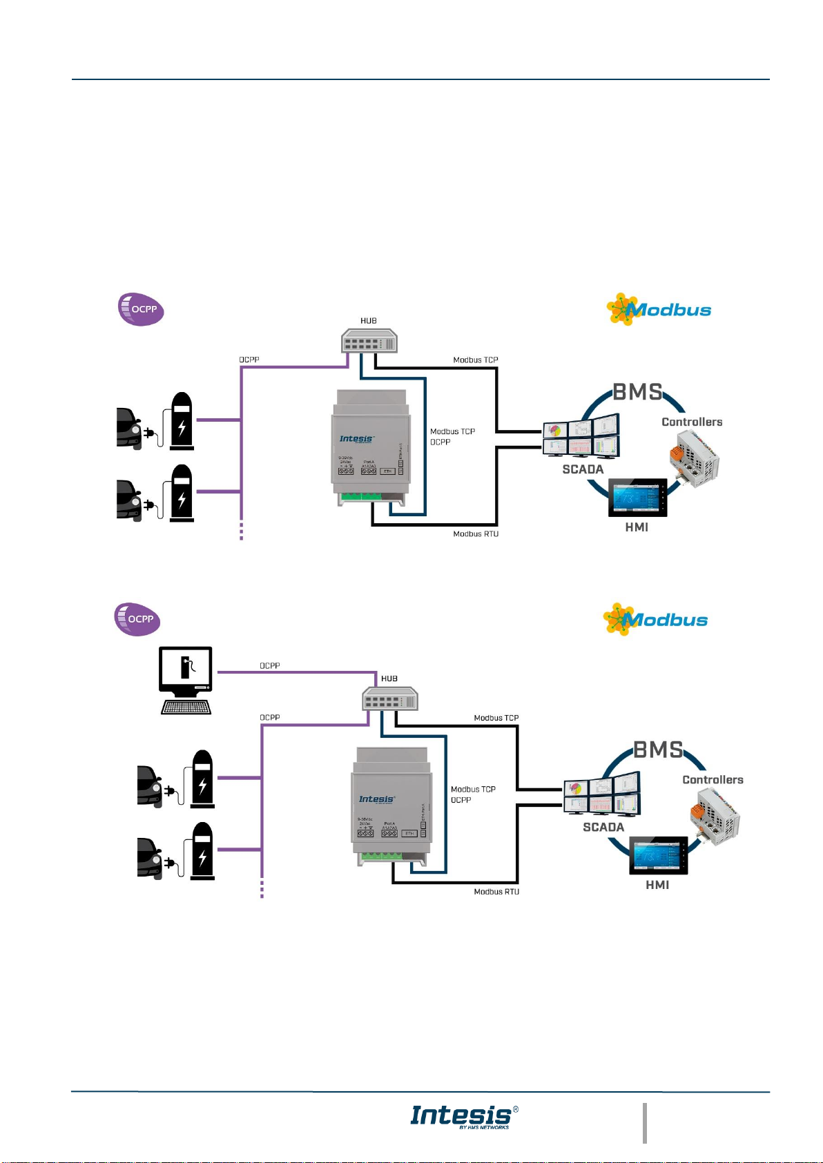
Fig 1.1 Use case 1: Integration of OCPP EV Charging points into a Modbus BMS (TCP or RTU)
Fig 1.2 Use case 2: Modbus gateway acting as an bridge between an external OCPP Central System and
OCPP chargers
Page 6
Intesis® Modbus – OCPP User Manual r1.2 eng
© HMS Industrial Networks S.L.U - All rights reserved
This information is subject to change without notice
URL https://www.intesis.com
6 / 41
2 System configuration
In the following chapter it´s described a set of general rules to perform the integration of EV charging points (chargers)
and their connectors to the Intesis gateway.
Please keep in mind each charger is different and must have access to OCPP 1.6 networks to enable communication
with Intesis gateway.
The configuration of the chargers must be applied when working in both OCPP modes: BMS Central System and
External Central system.
Charger(s) configuration
In order to work with Intesis gateway, each charger connected must be enabled to work in an OCPP network.
To do so, check on the User Manual or documentation of the EV charger´s manufacturer. Once the OCPP connection
is enabled, you should be able to change or copy the charger´s ID and configure IP settings of the OCPP network
and some other parameters of the charger.
When changing the IP settings, note that the Intesis gateway uses the not secure version of OCPP 1.6J WebSocket,
therefore the URL should be set in the form: ws://xxx.xxx.xxx.xxx:9000/ChargerID. The TCP port by default is
9000, but it can be changed in MAPS as described in point 2.2.
Important: Note down the ChargerID to use it later when configuring Intesis MAPS.
Intesis Gateway configuration using MAPS
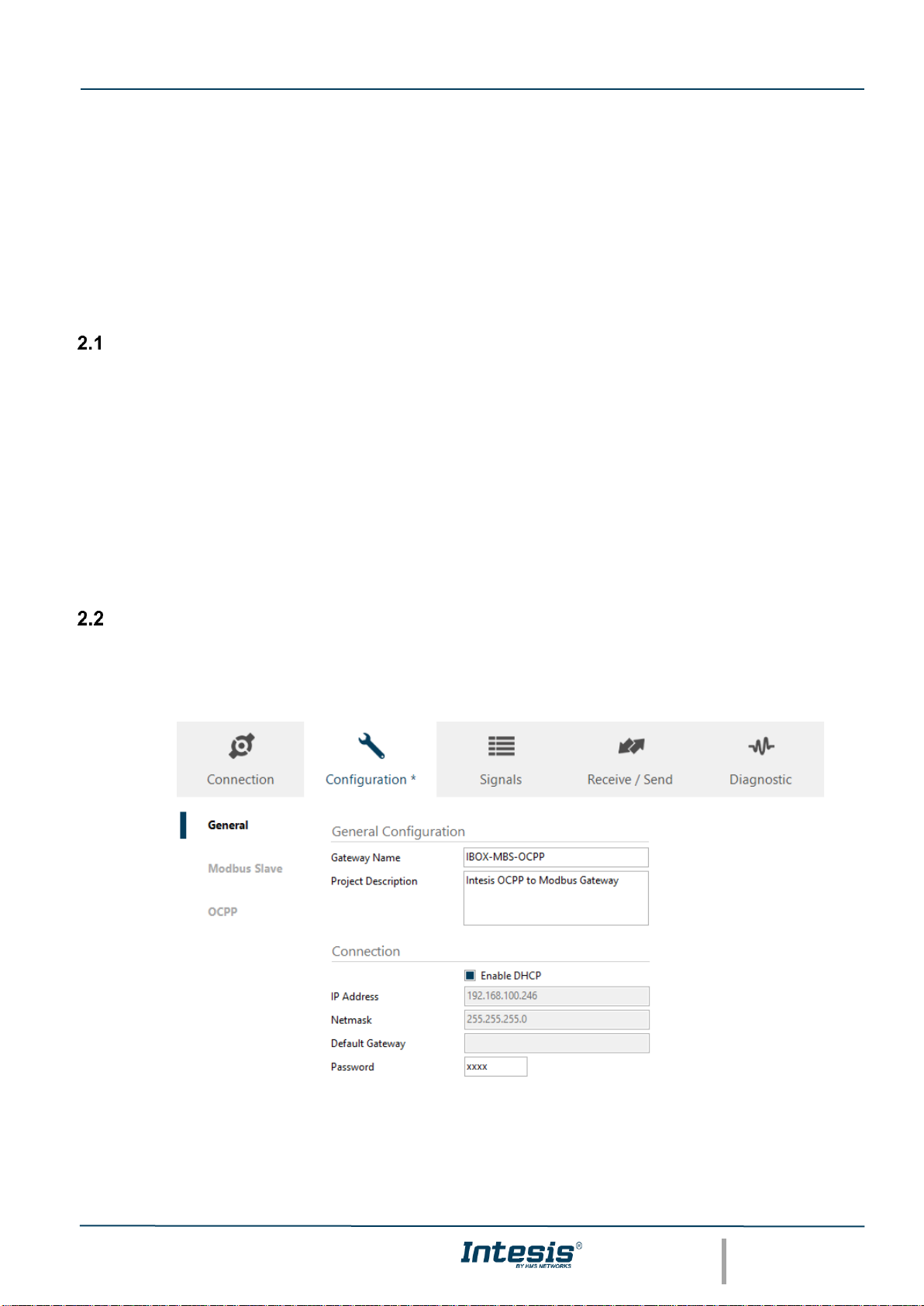
1. Start-up MAPS software in your PC and use the project template: IBOX-MBS-OCPP-template.
2. Go to Configuration, General tab and configure the networks details. Keep in mind the configuration used in
the Charger(s)
3. Configure the Modbus slave/server details as required by your network on the Modbus Slave tab.
Page 7
Intesis® Modbus – OCPP User Manual r1.2 eng
© HMS Industrial Networks S.L.U - All rights reserved
This information is subject to change without notice
URL https://www.intesis.com
7 / 41
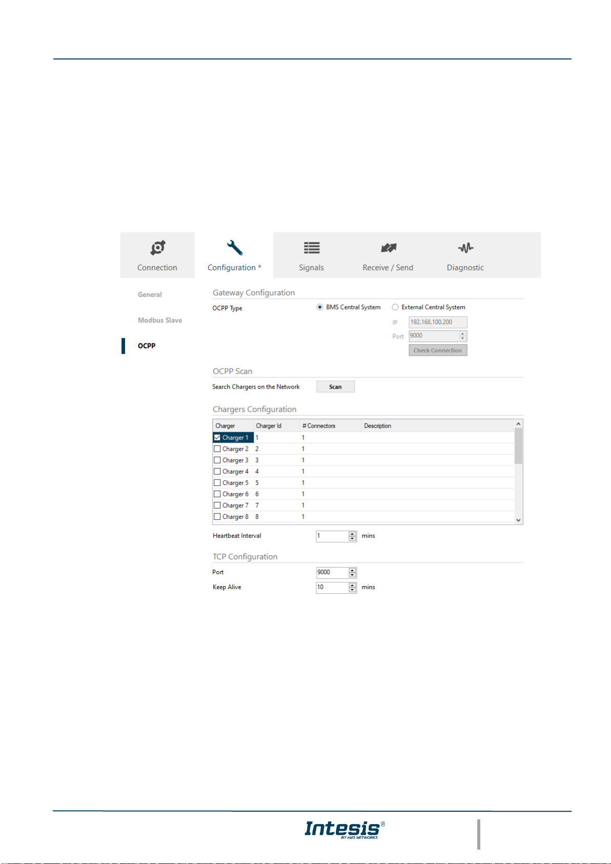
4. Use the OCPP tab to configure the Chargers in your network. Please note that this configuration must be
done, and it is the same, for both OCPP working modes. There are 2 different options to perform the set-up:
a. Manually
Gateway Configuration: a choice is given for the OCCP Central System to be implemented on the
BMS interface (select BMS) or on an OCCP external Central System (select External)
Chargers Configuration: Select as many Chargers and Connectors as you require to integrate
(Note Intesis gateway is offered in 2 versions: 1 charger + 7 connectors or up 20 chargers + 7
connector each)
Use the Charger ID previously noted when configuring the chargers to identify each of the units.
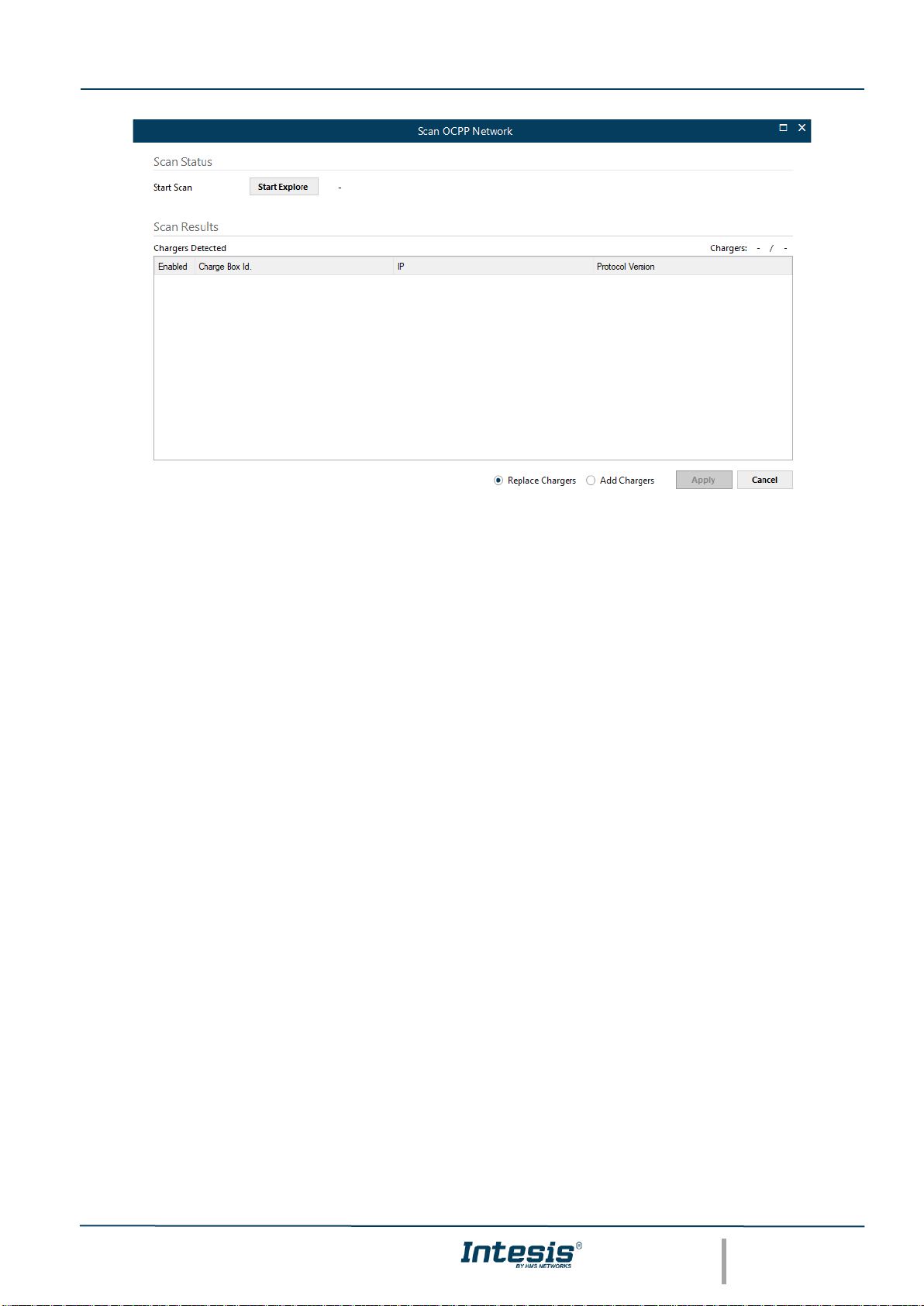
b. OCPP SCAN:
This option will list as many chargers in the network that are trying to connect to Intesis gateway.
IMPORTANT! Keep in mind that the Scan option will only list the chargers that are already configured
to connect to the Intesis gateway (same network)
Page 8
Intesis® Modbus – OCPP User Manual r1.2 eng
© HMS Industrial Networks S.L.U - All rights reserved
This information is subject to change without notice
URL https://www.intesis.com
8 / 41
Once the setup is done, you can use the Heartbeat interval to adjust the time the chargers use this parameter
to communicate with the Central System.
Furthermore, the TCP configuration can be adapted to change the port enabled for OCPP communication.
By default, it is always 9000.
5. Go to Connection tab to connect MAPS/PC to the Intesis gateway.
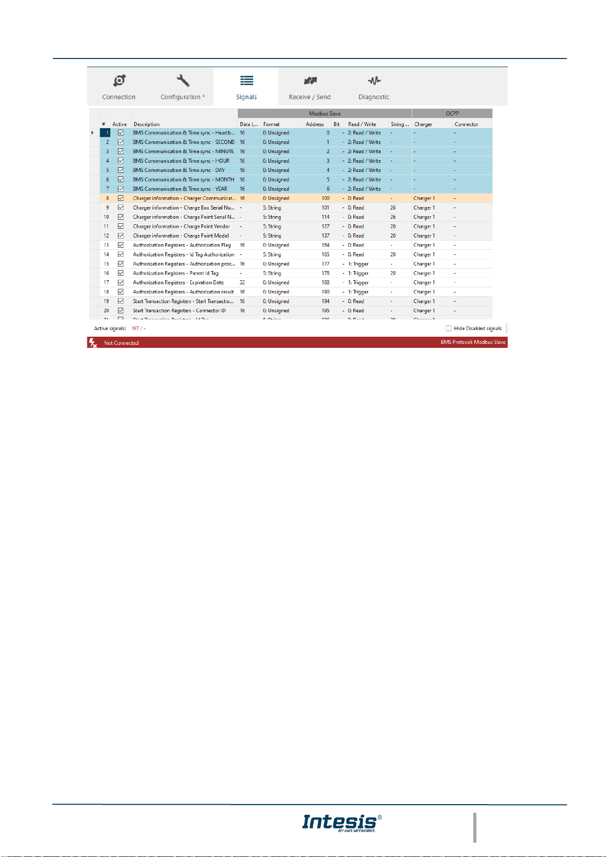
6. Use the Signals tab to activate the signals required for the project. This tab will be updated according the
number of Chargers and Connectors defined in the OCPP tab and the OCPP operation mode.
a. When working as BMS Central system: All signals are available as Modbus registers to implement
the necessary operations to work as an OCPP central system with the Modbus BMS.
b. When working with an External OCPP Central system: Only measurements and information signals
are available as Modbus registers for integration and supervision from a Modbus BMS.
IMPORTANT! Not all the available charger signals are active by default. User might require activating some
signals according to each project needs. Max limit is 10.000 signals per project.
Page 9
Intesis® Modbus – OCPP User Manual r1.2 eng
© HMS Industrial Networks S.L.U - All rights reserved
This information is subject to change without notice
URL https://www.intesis.com
9 / 41
7. Go to Receive/Send and send the project to the Intesis gateway.
8. After 30 seconds, connect again to the Intesis gateway and go to Diagnostic tab to visualize the
communication status in both sides: Modbus and OCPP.
Page 10

Intesis® Modbus – OCPP User Manual r1.2 eng
© HMS Industrial Networks S.L.U - All rights reserved
This information is subject to change without notice
URL https://www.intesis.com
10 / 41
Working with a BMS as a Central System: Integration into a Modbus BMS
This section describes the sequences and workflows required to transmit information from OCPP to a Modbus
client/master using all the available OCPP operations in the Intesis gateway.
2.3.1 Available Operations
2.3.1.1 Time synchronization
The Central System (Modbus BMS or PLC) can synchronize periodically the time with the Intesis gateway, so this
one can do the same with the EV´s charger.
Considering that the synchronization between the BMS and the gateway happens periodically, the synchronization
between the Intesis gateway and the charger though, only happens during the charger´s start up process. Check
with the manufacturer´s manual to verify this functionality in the charger.
It is possible to change the date from a Modbus client/master using the dedicated Modbus registers, however these
registers must be written in the gateway within 15 seconds time in between writing commands; after this time the
gateway will take this actual registers as valid and update its internal clock. Note that all time registers must be
written, partial dates are not valid.
Moreover, the time synchronization between the gateway and the charger it´s only performed with the message
BootNotification.req, triggered by the charger, so the gateway responds with the date information. The charger
should only launch the BootNotification.req in two cases:
- Charger´s reboot process
- When requested by the Central System using the registers of the command TriggerMessage, requesting the
BootNotification.req.
Check the diagram SEQ_SyncDateTime in Appendix 1 to review the communication workflow between the 3 systems
and check the Modbus registers involved.
2.3.1.2 Local start charging operation
Typically, the start of a charging operation can be done locally when the user initiates the charge using a RFID card
at the charging point.
After this action, the charger initiates the operation to validate the user, checking the card ID´s number with its local
authorization list (in case this option is available in the charger) If the local authorization method cannot be performed,
an authorization message is triggered to the Central System (BMS) so this one can authorize or not the user´s ID
card.
If the user is not authorized, the charging operation is cancelled. If the user is authorized, the charger initiates another
operation with the user´s information and sends a notification to the Central system (BMS) to initiate the charging
operation.
Page 11
Intesis® Modbus – OCPP User Manual r1.2 eng
© HMS Industrial Networks S.L.U - All rights reserved
This information is subject to change without notice
URL https://www.intesis.com
11 / 41
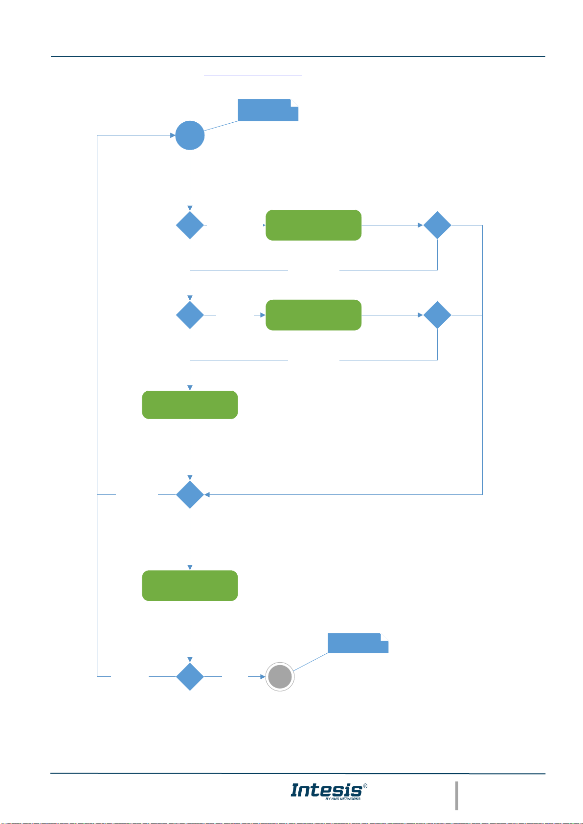
Check the following diagram and SEQ_StartTransaction in Appendix 1 to review the communication workflow
between the 3 systems and check the Modbus registers involved.
SEQ_Authorize
Authorized
SEQ_StartTransactio
n
Accepted
Not Author ized
Not Accepted
Check idTag in Local
Cache
Local Cache Disabled
Local Cache Enabled
Check idTag in Local
Authorization List
Local
Authorization
List Enabled
Local Authorization List
Disabled
idTag Pres ent
idTag NOT present
idTag NOT present
User passes a card
throught card reader
Connector is charging
Page 12

Intesis® Modbus – OCPP User Manual r1.2 eng
© HMS Industrial Networks S.L.U - All rights reserved
This information is subject to change without notice
URL https://www.intesis.com
12 / 41
2.3.1.3 Local stop charging operation
A user can stop the charging operation locally from the charging point. This is typically done by the charging point
when the user passes a RFID or ID card over the charger´s reader.
After this action, the charger will check if the user that is requesting the stop operation is the same that initiated it. If
that is the case, the stop operation is triggered directly without starting any other authentication method. If that is not
the case, the charger should check if the user that is requesting the stop operation belongs to the same user´s group
(parentIdTag) through the local cache list, the local authorization list and lastly through the standard authorization
process with the Central system (BMS)
If after this authentication process the user is denied, the stop operation will be cancelled. If the user is accepted, the
charger will send another message to the Central system so it can be accepted and stop the charging operation.
Page 13

Intesis® Modbus – OCPP User Manual r1.2 eng
© HMS Industrial Networks S.L.U - All rights reserved
This information is subject to change without notice
URL https://www.intesis.com
13 / 41
Check the following diagram and SEQ_StopTransaction in Appendix 1 to review the communication workflow
between the 3 systems and check the Modbus registers involved.
SEQ_Authorize
Authorized
SEQ_StopTransaction
Accepted
Not Authorized
Not Accep te d
Check idTag in Local
Cache
Local Cache Disabled
Local Cache Enabled
Check idTag in Local
Authorization List
Local
Authoriza tion
List Enabled
Local Autho rization List
Disable d
idTag Pres ent
idTag NO T present
idTag NO T present
idTag != tra nsactionId.idTag
Check if
idTag.Par entIdTag == transactionId.idTag.ParentIdTag
idTag == tr ansactionId.idTag
User passes a card
throught card reader
Connector stops charging
and goes to available
status
Page 14

Intesis® Modbus – OCPP User Manual r1.2 eng
© HMS Industrial Networks S.L.U - All rights reserved
This information is subject to change without notice
URL https://www.intesis.com
14 / 41
2.3.1.4 Remote Start charging operation
The remote start of a charging operation begins when the central system (BMS) requests a new charging transaction
for a specific user (idTag).
If the charger accepts this transaction, depending on its configuration, the charger could require initiating a completely
new Authorization process. In case the charger is not configured this way, the Authentication process would not be
required, and the start of the charging operation will begin.
Check previous chapter 2.3.1.2 to review the Authorization operation.
Check points the following diagram and SEQ_RemoteStartTransaction to review the communication workflow
between the 3 systems and check the Modbus registers involved.
Page 15

Intesis® Modbus – OCPP User Manual r1.2 eng
© HMS Industrial Networks S.L.U - All rights reserved
This information is subject to change without notice
URL https://www.intesis.com
15 / 41
SEQ_Authorize
Authorized
SEQ_StartTransactio
n
Accepted
Not Authorized
Not Accepte d
Check idTag in Local
Cache
Local Cache Disabled
Local Cache Enabled
Check idTag in Local
Authorization List
Local
Authorization
List Enabled
Local Author ization List
Disabled
idTag Pres ent
idTag NOT pr esent
idTag NOT pr esent
SEQ_RemoteStartTra
nsaction
AuthorizeRe moteTxRequests == tr ue
AuthorizeRe moteTxRequests == f alse
Accepted
Rejected
BMS starts a new
transaction
Connector is charging
AuthorizeRemoteTxRequ
ests is a configuration key
in the Charger
configuration
Page 16

Intesis® Modbus – OCPP User Manual r1.2 eng
© HMS Industrial Networks S.L.U - All rights reserved
This information is subject to change without notice
URL https://www.intesis.com
16 / 41
2.3.1.5 Remote Stop charging operation
The remote start of a charging operation begins when the central system (BMS) requests a Stop transaction.
If the charger accepts this request, it will stop the charging operation and will notify the Central system.
Check points the following diagram and SEQ_RemoteStopTransaction to review the communication workflow
between the 3 systems and check the Modbus registers involved.
SEQ_StopTransaction
Accepted
Not Accepted
SEQ_RemoteStopTra
nsaction
Rejected
Accepted
BMS request to stop a
transactionId
Connector stops charging
and goes to available
status
Page 17

Intesis® Modbus – OCPP User Manual r1.2 eng
© HMS Industrial Networks S.L.U - All rights reserved
This information is subject to change without notice
URL https://www.intesis.com
17 / 41
2.3.1.6 How to read values from the charger
To read the values or measurements that the charger has available in OCPP, the user needs to configure them in
the Charger´s configuration tool. Refer to charger´s user manual to learn which ones are present in the charger and
how to activate them to be ready for OCPP communication.
Note that this type of notifications will only take place when there is an active transaction, otherwise the charger will
not notify any value by itself.
In case an update of a specific value is required, the BMS can request an update using the “Trigger Message”
registers and requesting them with a message MessageValues.
Refer to Intesis Modbus Register table to check the values implemented in the gateway.
2.3.1.7 Local Authorization list management
The Local Authorization list of the chargers can be managed by the central system (BMS) using the sequence
described in the appendix 1: SEQ_SendLocalList
Using this sequence, the BMS can add, edit or delete elements in this list. Note that the BMS should write these
registers one by one and one after another.
Each edition of the list will change its version. In order to check the version that the charger is using, the central
system can request this value using the operation described in Appendix 1 SEQ_GetLocalListVersion
Working with an External OCPP Central system: Read-only Modbus registers
This section describes the basic information that a Modbus client can read from the gateway when is connected to
an external OCPP central system.
2.4.1 Available Operations
When working in this mode, no OCPP operations are available since the gateway is acting as a bridge between an
External OCPP Central system and OCPP enabled chargers.
2.4.1.1 How to read values from the chargers in Modbus
When working as an External OCPP Central system mode, the Intesis gateway will act as a bridge between OCPP
chargers and an external OCPP central system, offering only OCPP measurements and values from the chargers to
the Modbus BMS.
Note that these values will only be updated in the gateway when the External OCPP and the chargers have engaged
in communication. When working in this mode, all the OCPP sequences and operations are managed by the External
OCPP system, therefore the Intesis gateway is merely updating the values that are available in the OCPP
communication.
To read the values or measurements that the charger has available in OCPP, the user needs to configure them in
the Charger´s configuration tool. Refer to charger´s user manual to learn which ones are present in the charger and
how to activate them to be ready for OCPP communication.
Once knowing which measurements are available in the OCPP system, they can be activated in the gateway to be
ready as Modbus registers for the Modbus BMS.
Refer to Intesis Modbus Register table to check the values implemented in the gateway.
Page 18

Intesis® Modbus – OCPP User Manual r1.2 eng
© HMS Industrial Networks S.L.U - All rights reserved
This information is subject to change without notice
URL https://www.intesis.com
18 / 41
Appendix 1 – UML Sequence diagrams
SEQ_SyncDateTime
Page 19

Intesis® Modbus – OCPP User Manual r1.2 eng
© HMS Industrial Networks S.L.U - All rights reserved
This information is subject to change without notice
URL https://www.intesis.com
19 / 41
SEQ_Authorize
Page 20

Intesis® Modbus – OCPP User Manual r1.2 eng
© HMS Industrial Networks S.L.U - All rights reserved
This information is subject to change without notice
URL https://www.intesis.com
20 / 41
SEQ_StartTransaction
Page 21

Intesis® Modbus – OCPP User Manual r1.2 eng
© HMS Industrial Networks S.L.U - All rights reserved
This information is subject to change without notice
URL https://www.intesis.com
21 / 41
SEQ_StopTransaction
Page 22

Intesis® Modbus – OCPP User Manual r1.2 eng
© HMS Industrial Networks S.L.U - All rights reserved
This information is subject to change without notice
URL https://www.intesis.com
22 / 41
SEQ_RemoteStartTransaction
SEQ_RemoteStopTransaction
Page 23

Intesis® Modbus – OCPP User Manual r1.2 eng
© HMS Industrial Networks S.L.U - All rights reserved
This information is subject to change without notice
URL https://www.intesis.com
23 / 41
SEQ_SendLocalList
SEQ_GetLocalListVersion
Page 24

Intesis® Modbus – OCPP User Manual r1.2 eng
© HMS Industrial Networks S.L.U - All rights reserved
This information is subject to change without notice
URL https://www.intesis.com
24 / 41
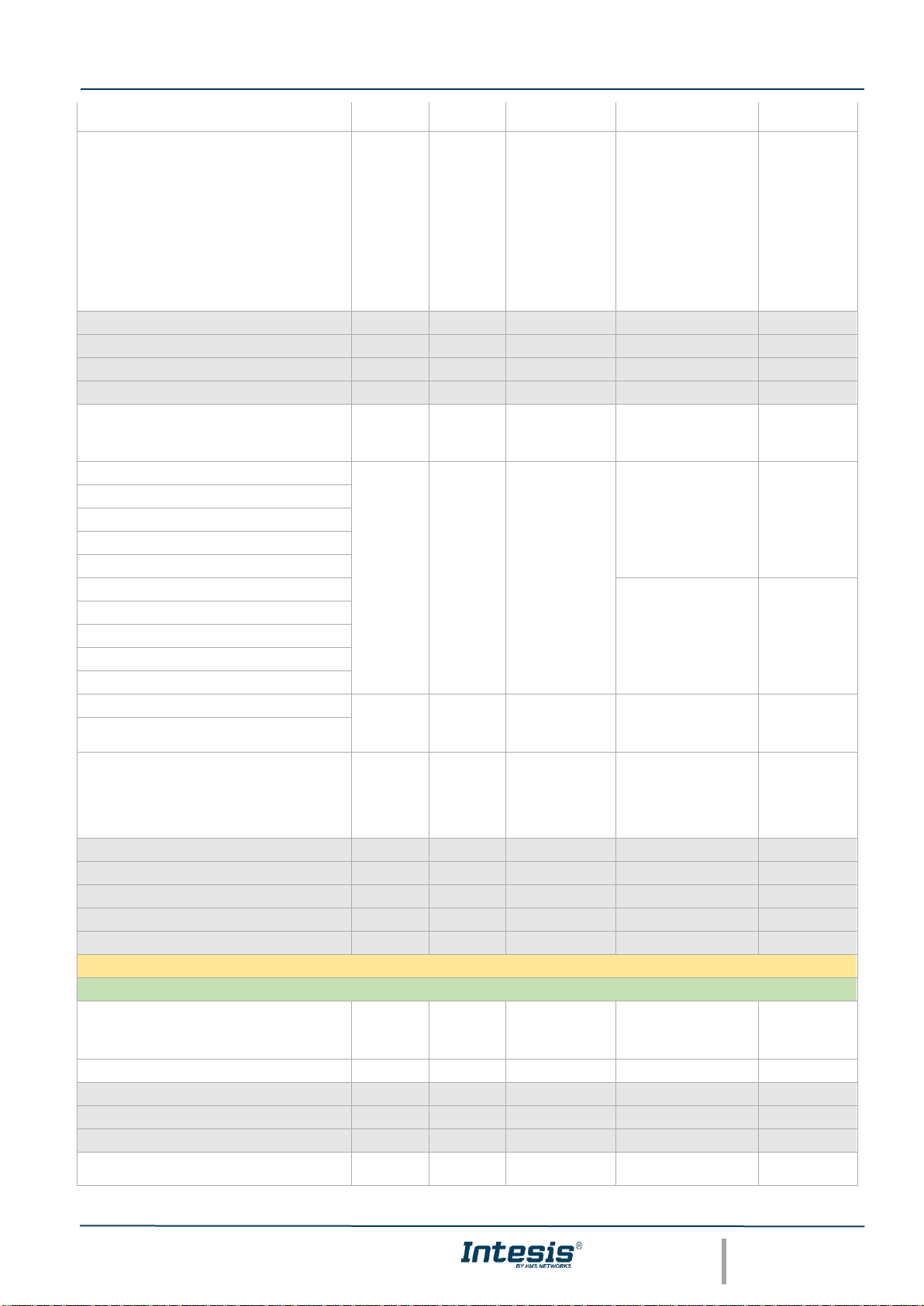
Appendix 2 – Modbus register map
Address
Format
R/RW/W
(trigger)
Signal
Values
Comments
BMS Communication & Time sync
0
Integer
RW
Heartbeat
BMS should set to 1
periodically and
gateway will set to 0 to
check communication
is open
Virtual signal.
Only available
in BMS
Central
system model
1
Integer
RW
SECOND
Only available
in BMS
Central
system model
2
Integer
RW
MINUTE
Only available
in BMS
Central
system model
3
Integer
RW
HOUR
Only available
in BMS
Central
system model
4
Integer
RW
DAY
Only available
in BMS
Central
system model
5
Integer
RW
MONTH
Only available
in BMS
Central
system model
6
Integer
RW
YEAR
Only available
in BMS
Central
system model
Charger Signals (xx = 0 to 19)
Charger information
100 + (xx * 2000) + 0
Integer
R
Charger
Communication
status
0 = OK
1 = Communication
Error
100 + (xx * 2000) + 1
String
R
Charge Box
Serial Number
100 + (xx * 2000) + 2
100 + (xx * 2000) + 3
100 + (xx * 2000) + 4
100 + (xx * 2000) + 5
100 + (xx * 2000) + 6
100 + (xx * 2000) + 7
100 + (xx * 2000) + 8
100 + (xx * 2000) + 9
100 + (xx * 2000) + 10
100 + (xx * 2000) + 11
100 + (xx * 2000) + 12
100 + (xx * 2000) + 13
100 + (xx * 2000) + 14
String
R
Charge Point
Serial Number
100 + (xx * 2000) + 15
100 + (xx * 2000) + 16
100 + (xx * 2000) + 17
100 + (xx * 2000) + 18
100 + (xx * 2000) + 19
Page 25

Intesis® Modbus – OCPP User Manual r1.2 eng
© HMS Industrial Networks S.L.U - All rights reserved
This information is subject to change without notice
URL https://www.intesis.com
25 / 41
100 + (xx * 2000) + 20
100 + (xx * 2000) + 21
100 + (xx * 2000) + 22
100 + (xx * 2000) + 23
100 + (xx * 2000) + 24
100 + (xx * 2000) + 25
100 + (xx * 2000) + 26
100 + (xx * 2000) + 27
String
R
Charge Point
Vendor
100 + (xx * 2000) + 28
100 + (xx * 2000) + 29
100 + (xx * 2000) + 30
100 + (xx * 2000) + 31
100 + (xx * 2000) + 32
100 + (xx * 2000) + 33
100 + (xx * 2000) + 34
100 + (xx * 2000) + 35
100 + (xx * 2000) + 36
100 + (xx * 2000) + 37
String
R
Charge Point
Model
100 + (xx * 2000) + 38
100 + (xx * 2000) + 39
100 + (xx * 2000) + 40
100 + (xx * 2000) + 41
100 + (xx * 2000) + 42
100 + (xx * 2000) + 43
100 + (xx * 2000) + 44
100 + (xx * 2000) + 45
100 + (xx * 2000) + 46
Messages to CS
Authorization Registers
100 + (xx * 2000) + 64
Integer
R
Authorization
Flag
0 = No operation
pending
1 = Operation pending
Only available
in BMS
Central
system model
100 + (xx * 2000) + 65
String
R
Id Tag
Authorization
Only available
in BMS
Central
system model
100 + (xx * 2000) + 66
100 + (xx * 2000) + 67
100 + (xx * 2000) + 68
100 + (xx * 2000) + 69
100 + (xx * 2000) + 70
100 + (xx * 2000) + 71
100 + (xx * 2000) + 72
100 + (xx * 2000) + 73
100 + (xx * 2000) + 74
100 + (xx * 2000) + 75
Not used
100 + (xx * 2000) + 76
Not used
100 + (xx * 2000) + 77
Integer
W
Authorization
processed
0 = Not processed
1 = Processed
Only available
in BMS
Central
system model
100 + (xx * 2000) + 78
String
W
Parent Id Tag
Page 26

Intesis® Modbus – OCPP User Manual r1.2 eng
© HMS Industrial Networks S.L.U - All rights reserved
This information is subject to change without notice
URL https://www.intesis.com
26 / 41
100 + (xx * 2000) + 79
Only available
in BMS
Central
system model
100 + (xx * 2000) + 80
100 + (xx * 2000) + 81
100 + (xx * 2000) + 82
100 + (xx * 2000) + 83
100 + (xx * 2000) + 84
100 + (xx * 2000) + 85
100 + (xx * 2000) + 86
100 + (xx * 2000) + 87
100 + (xx * 2000) + 88
DateTime
W
Expiration Date
Only available in
BMS Central
system model.
Note signal is in
Epoch time (Unix
Time stamp)
100 + (xx * 2000) + 89
100 + (xx * 2000) + 90
Integer
W
Authorization
result
0 = Accepted
1 = Blocked
2 = Expired
3 = Invalid
4 = Concurrent
Transaction
Only available
in BMS
Central
system model
100 + (xx * 2000) + 91
Not used
100 + (xx * 2000) + 92
Not used
100 + (xx * 2000) + 93
Not used
Start Transaction Registers
100 + (xx * 2000) + 94
Integer
R
Start
Transaction Flag
0 = No operation
pending
1 = Operation pending
Only available
in BMS
Central
system model
100 + (xx * 2000) + 95
Integer
R
Connector ID
Only available
in BMS
Central
system model
100 + (xx * 2000) + 96
String
R
Id Tag
Only available
in BMS
Central
system model
100 + (xx * 2000) + 97
100 + (xx * 2000) + 98
100 + (xx * 2000) + 99
100 + (xx * 2000) + 100
100 + (xx * 2000) + 101
100 + (xx * 2000) + 102
100 + (xx * 2000) + 103
100 + (xx * 2000) + 104
100 + (xx * 2000) + 105
100 + (xx * 2000) + 106
Float
R
Meter Value
Only available
in BMS
Central
system model
100 + (xx * 2000) + 107
100 + (xx * 2000) + 108
Integer
R
Reservation ID
Only available
in BMS
Central
system model
100 + (xx * 2000) + 109
DateTime
R
Timestamp
Only available
in BMS
Central
system model
100 + (xx * 2000) + 110
100 + (xx * 2000) + 111
Not used
100 + (xx * 2000) + 112
Not used
100 + (xx * 2000) + 113
Not used
Page 27

Intesis® Modbus – OCPP User Manual r1.2 eng
© HMS Industrial Networks S.L.U - All rights reserved
This information is subject to change without notice
URL https://www.intesis.com
27 / 41
100 + (xx * 2000) + 114
Integer
W
Start
Transaction
Processed
0 = Not processed
1 = Processed
Only available
in BMS
Central
system model
100 + (xx * 2000) + 115
String
W
Parent Id Tag
Only available
in BMS
Central
system model
100 + (xx * 2000) + 116
100 + (xx * 2000) + 117
100 + (xx * 2000) + 118
100 + (xx * 2000) + 119
100 + (xx * 2000) + 120
100 + (xx * 2000) + 121
100 + (xx * 2000) + 122
100 + (xx * 2000) + 123
100 + (xx * 2000) + 124
100 + (xx * 2000) + 125
DateTime
W
Expiration Date
Only available
in BMS
Central
system model
100 + (xx * 2000) + 126
100 + (xx * 2000) + 127
Integer
W
Authorization
result
0 = Accepted
1 = Blocked
2 = Expired
3 = Invalid
4 = Concurrent
Transaction
Only available
in BMS
Central
system model
100 + (xx * 2000) + 128
Integer
W
Transaction ID
Only available
in BMS
Central
system model
100 + (xx * 2000) + 129
Not used
100 + (xx * 2000) + 130
Not used
100 + (xx * 2000) + 131
Not used
100 + (xx * 2000) + 132
Not used
100 + (xx * 2000) + 133
Not used
Stop Transaction Registers
100 + (xx * 2000) + 134
Integer
R
Stop
Transaction Flag
0 = No operation
pending
1 = Operation pending
Only available
in BMS
Central
system model
100 + (xx * 2000) + 135
String
R
Id Tag
Only available
in BMS
Central
system model
100 + (xx * 2000) + 136
100 + (xx * 2000) + 137
100 + (xx * 2000) + 138
100 + (xx * 2000) + 139
100 + (xx * 2000) + 140
100 + (xx * 2000) + 141
100 + (xx * 2000) + 142
100 + (xx * 2000) + 143
100 + (xx * 2000) + 144
100 + (xx * 2000) + 145
Float
R
Meter Value
Only available
in BMS
Central
system model
100 + (xx * 2000) + 146
100 + (xx * 2000) + 147
DateTime
R
Timestamp
Only available
in BMS
Central
system model
100 + (xx * 2000) + 148
100 + (xx * 2000) + 149
Integer
R
Transaction ID
Only available
in BMS
Page 28
Intesis® Modbus – OCPP User Manual r1.2 eng
© HMS Industrial Networks S.L.U - All rights reserved
This information is subject to change without notice
URL https://www.intesis.com
28 / 41
Central
system model
100 + (xx * 2000) + 150
Integer
R
Reason
0 = DeAuthorized
1 = EmergencyStop
2 = EVDisconnected
3 = HardReset
4 = Local
5 = Other
6 = PowerLoss
7 = Reboot
8 = Remove
9 = SoftReset
10 = UnlockCommand
Only available
in BMS
Central
system model
100 + (xx * 2000) + 151
Not used
100 + (xx * 2000) + 152
Not used
100 + (xx * 2000) + 153
Not used
100 + (xx * 2000) + 154
Not used
100 + (xx * 2000) + 155
Integer
W
Stop
Transaction
Processed
0 = Not processed
1 = Processed
Only available
in BMS
Central
system model
100 + (xx * 2000) + 156
String
W
Parent Id Tag
Only available
in BMS
Central
system model
100 + (xx * 2000) + 157
100 + (xx * 2000) + 158
100 + (xx * 2000) + 159
100 + (xx * 2000) + 160
100 + (xx * 2000) + 161
Only available
in BMS
Central
system model
100 + (xx * 2000) + 162
100 + (xx * 2000) + 163
100 + (xx * 2000) + 164
100 + (xx * 2000) + 165
100 + (xx * 2000) + 166
DateTime
W
Expiration Date
Only available
in BMS
Central
system model
100 + (xx * 2000) + 167
100 + (xx * 2000) + 168
Integer
W
Authorization
result
0 = Accepted
1 = Blocked
2 = Expired
3 = Invalid
4 = Concurrent
Transaction
Only available
in BMS
Central
system model
100 + (xx * 2000) + 169
Not used
100 + (xx * 2000) + 170
Not used
100 + (xx * 2000) + 171
Not used
100 + (xx * 2000) + 172
Not used
100 + (xx * 2000) + 173
Not used
Messages from CS
Cancel Reservation Registers
100 + (xx * 2000) + 256
Integer
RW
Cancel
Reservation
Flag
0 = No operation
pending
1 = Operation pending
Only available
in BMS
Central
system model
100 + (xx * 2000) + 257
Integer
W
Reservation ID
100 + (xx * 2000) + 258
Not used
100 + (xx * 2000) + 259
Not used
100 + (xx * 2000) + 260
Not used
100 + (xx * 2000) + 261
Integer
R
Result
0 = Accepted
1 = Rejected
Only available
in BMS
Page 29

Intesis® Modbus – OCPP User Manual r1.2 eng
© HMS Industrial Networks S.L.U - All rights reserved
This information is subject to change without notice
URL https://www.intesis.com
29 / 41
Central
system model
100 + (xx * 2000) + 262
Not used
100 + (xx * 2000) + 263
Not used
100 + (xx * 2000) + 264
Not used
100 + (xx * 2000) + 265
Not used
Clear Caché Registers
100 + (xx * 2000) + 266
Integer
RW
Clear Caché
Flag
0 = No operation
pending
1 = Operation pending
Only available
in BMS
Central
system model
100 + (xx * 2000) + 267
Not used
100 + (xx * 2000) + 268
Not used
100 + (xx * 2000) + 269
Not used
100 + (xx * 2000) + 270
Not used
100 + (xx * 2000) + 271
Integer
R
Result
0 = Accepted
1 = Rejected
Only available
in BMS
Central
system model
100 + (xx * 2000) + 272
Not used
100 + (xx * 2000) + 273
Not used
100 + (xx * 2000) + 274
Not used
100 + (xx * 2000) + 275
Not used
Clear Charging Profile Registers
100 + (xx * 2000) + 276
Integer
RW
Clear Charging
Profile Flag
0 = No operation
pending
1 = Operation pending
Only available
in BMS
Central
system model
100 + (xx * 2000) + 277
Integer
W
Profile ID
Only available
in BMS
Central
system model
100 + (xx * 2000) + 278
Integer
W
Connector ID
Only available
in BMS
Central
system model
100 + (xx * 2000) + 279
Integer
W
Charging Profile
Purpose
Only available
in BMS
Central
system model
100 + (xx * 2000) + 280
Integer
W
Stack Level
Only available
in BMS
Central
system model
100 + (xx * 2000) + 281
Not used
100 + (xx * 2000) + 282
Not used
100 + (xx * 2000) + 283
Integer
R
Result
0 = Accepted
4 = Unknown
Only available
in BMS
Central
system model
100 + (xx * 2000) + 284
Not used
100 + (xx * 2000) + 285
Not used
Get Local List Version
100 + (xx * 2000) + 286
Integer
RW
Get Local List
Flag
0 = No operation
pending
1 = Operation pending
Only available
in BMS
Central
system model
100 + (xx * 2000) + 287
Not used
100 + (xx * 2000) + 288
Not used
100 + (xx * 2000) + 289
Not used
100 + (xx * 2000) + 290
Not used
Page 30

Intesis® Modbus – OCPP User Manual r1.2 eng
© HMS Industrial Networks S.L.U - All rights reserved
This information is subject to change without notice
URL https://www.intesis.com
30 / 41
100 + (xx * 2000) + 291
Integer
R
Version
Only available
in BMS
Central
system model
100 + (xx * 2000) + 292
Not used
100 + (xx * 2000) + 293
Not used
100 + (xx * 2000) + 294
Not used
100 + (xx * 2000) + 295
Not used
Reserve Now Registers
100 + (xx * 2000) + 296
Integer
RW
Reserve Now
Flag
0 = No operation
pending
1 = Operation pending
Only available
in BMS
Central
system model
100 + (xx * 2000) + 297
Integer
W
Connector ID
Only available
in BMS
Central
system model
100 + (xx * 2000) + 298
DateTime
W
Expiration Date
Only available
in BMS
Central
system model
100 + (xx * 2000) + 299
100 + (xx * 2000) + 300
String
W
Id Tag
Only available
in BMS
Central
system model
100 + (xx * 2000) + 301
100 + (xx * 2000) + 302
100 + (xx * 2000) + 303
100 + (xx * 2000) + 304
100 + (xx * 2000) + 305
100 + (xx * 2000) + 306
100 + (xx * 2000) + 307
100 + (xx * 2000) + 308
100 + (xx * 2000) + 309
100 + (xx * 2000) + 310
String
W
Parent Id Tag
Only available
in BMS
Central
system model
100 + (xx * 2000) + 311
100 + (xx * 2000) + 312
100 + (xx * 2000) + 313
100 + (xx * 2000) + 314
100 + (xx * 2000) + 315
100 + (xx * 2000) + 316
100 + (xx * 2000) + 317
100 + (xx * 2000) + 318
100 + (xx * 2000) + 319
100 + (xx * 2000) + 320
Integer
W
Reservation ID
Only available
in BMS
Central
system model
100 + (xx * 2000) + 321
Not used
100 + (xx * 2000) + 322
Not used
100 + (xx * 2000) + 323
Integer
R
Result of the
request
0 = Accepted
1 = Rejected
8 = Faulted
9 = Occupied
Only available
in BMS
Central
system model
100 + (xx * 2000) + 324
Not used
100 + (xx * 2000) + 325
Not used
Reset Registers
Page 31

Intesis® Modbus – OCPP User Manual r1.2 eng
© HMS Industrial Networks S.L.U - All rights reserved
This information is subject to change without notice
URL https://www.intesis.com
31 / 41
100 + (xx * 2000) + 326
Integer
RW
Reset Flag
0 = No operation
pending
1 = Operation pending
Only available
in BMS
Central
system model
100 + (xx * 2000) + 327
Not used
100 + (xx * 2000) + 328
Not used
100 + (xx * 2000) + 329
Not used
100 + (xx * 2000) + 330
Not used
100 + (xx * 2000) + 331
Integer
R
Status
Only available
in BMS
Central
system model
100 + (xx * 2000) + 332
Not used
100 + (xx * 2000) + 333
Not used
100 + (xx * 2000) + 334
Not used
100 + (xx * 2000) + 335
Not used
Send Local List registers
100 + (xx * 2000) + 336
Integer
RW
Send Local List
Flag
0 = No operation
pending
1 = Operation pending
Only available
in BMS
Central
system model
100 + (xx * 2000) + 337
Integer
W
Operation
1 = Add new entry
2 = Delete entry
3 = Modify entry
Only available
in BMS
Central
system model
100 + (xx * 2000) + 338
String
W
Id Tag
Only available
in BMS
Central
system model
100 + (xx * 2000) + 339
100 + (xx * 2000) + 340
100 + (xx * 2000) + 341
100 + (xx * 2000) + 342
100 + (xx * 2000) + 343
100 + (xx * 2000) + 344
100 + (xx * 2000) + 345
100 + (xx * 2000) + 346
100 + (xx * 2000) + 347
100 + (xx * 2000) + 348
String
W
Parent Id Tag
Only available
in BMS
Central
system model
100 + (xx * 2000) + 349
100 + (xx * 2000) + 350
100 + (xx * 2000) + 351
100 + (xx * 2000) + 352
100 + (xx * 2000) + 353
100 + (xx * 2000) + 354
100 + (xx * 2000) + 355
100 + (xx * 2000) + 356
100 + (xx * 2000) + 357
100 + (xx * 2000) + 358
DateTime
W
Expiration Date
Only available
in BMS
Central
system model
100 + (xx * 2000) + 359
100 + (xx * 2000) + 360
Integer
W
Authorization
Status
0 = Accepted
1 = Blocked
2 = Expired
3 = Invalid
4 = Concurrent
Transaction
Only available
in BMS
Central
system model
100 + (xx * 2000) + 361
Not used
Page 32

Intesis® Modbus – OCPP User Manual r1.2 eng
© HMS Industrial Networks S.L.U - All rights reserved
This information is subject to change without notice
URL https://www.intesis.com
32 / 41
100 + (xx * 2000) + 362
Not used
100 + (xx * 2000) + 363
Integer
R
Result of the
request
0 = Accepted
3 = NotSupported
8 = Failed
12 = VersionMismatch
Only available
in BMS
Central
system model
100 + (xx * 2000) + 364
Not used
100 + (xx * 2000) + 365
Not used
Trigger Message Registers
100 + (xx * 2000) + 366
Integer
RW
Trigger Message
Flag
0 = No operation
pending
1 = Operation pending
Only available
in BMS
Central
system model
100 + (xx * 2000) + 367
Integer
W
Requested
Message
0 = BootNotification
1 =
DiagnosticStatusNotifi
cation
2 =
FirmwareStatusNotific
ation
3 = Heartbeat
4 = MeterValues
5 = StatusNotification
Only available
in BMS
Central
system model
100 + (xx * 2000) + 368
Integer
W
Connector ID
Only available
in BMS
Central
system model
100 + (xx * 2000) + 369
Not used
100 + (xx * 2000) + 370
Not used
100 + (xx * 2000) + 371
Integer
R
Status
0 = Accepted
1 = Rejected
11 = NotImplemented
Only available
in BMS
Central
system model
100 + (xx * 2000) + 372
Not used
100 + (xx * 2000) + 373
Not used
100 + (xx * 2000) + 374
Not used
100 + (xx * 2000) + 375
Not used
Remote Start registers
100 + (xx * 2000) + 376
Integer
RW
Remote Start
Flag
0 = No operation
pending
1 = Operation pending
Only available
in BMS
Central
system model
100 + (xx * 2000) + 377
Integer
W
Connector ID
Only available
in BMS
Central
system model
100 + (xx * 2000) + 378
String
W
Id Tag
Only available
in BMS
Central
system model
100 + (xx * 2000) + 379
100 + (xx * 2000) + 380
100 + (xx * 2000) + 381
100 + (xx * 2000) + 382
100 + (xx * 2000) + 383
100 + (xx * 2000) + 384
100 + (xx * 2000) + 385
100 + (xx * 2000) + 386
100 + (xx * 2000) + 387
100 + (xx * 2000) + 388
Not used
100 + (xx * 2000) + 389
Not used
100 + (xx * 2000) + 390
Not used
100 + (xx * 2000) + 391
Not used
Page 33

Intesis® Modbus – OCPP User Manual r1.2 eng
© HMS Industrial Networks S.L.U - All rights reserved
This information is subject to change without notice
URL https://www.intesis.com
33 / 41
100 + (xx * 2000) + 392
Integer
R
Result of the
request
0 = Accepted
1 = Rejected
Only available
in BMS
Central
system model
100 + (xx * 2000) + 393
Not used
100 + (xx * 2000) + 394
Not used
100 + (xx * 2000) + 395
Not used
Remote Stop Registers
100 + (xx * 2000) + 396
Integer
RW
Remote Stop
Flag
0 = No operation
pending
1 = Operation pending
Only available
in BMS
Central
system model
100 + (xx * 2000) + 397
Integer
W
Transaction ID
Only available
in BMS
Central
system model
100 + (xx * 2000) + 398
Not used
100 + (xx * 2000) + 399
Not used
100 + (xx * 2000) + 400
Not used
100 + (xx * 2000) + 401
Integer
R
Status
0 = Accepted
1 = Rejected
Only available
in BMS
Central
system model
100 + (xx * 2000) + 402
Not used
100 + (xx * 2000) + 403
Not used
100 + (xx * 2000) + 404
Not used
100 + (xx * 2000) + 405
Not used
Connectors (yy = 0 to 7)
(512 + 100 + (xx * 2000) + (100 * yy)) + 0
Integer
RW
Unlock
Connector
(512 + 100 + (xx * 2000) + (100 * yy)) + 1
Integer
RW
Availabilty
0 = Inoperative
1 = Operative
(512 + 100 + (xx * 2000) + (100 * yy)) + 2
Integer
R
status
0 = Available
1 = Preparing
2 = Charging
3 = SuspendedEVSE
4 = SuspendedEV
5 = Finishing
6 = Reserved
7 = Unavailable
8 = Faulted
(512 + 100 + (xx * 2000) + (100 * yy)) + 3
Integer
R
errorCode
0 =
ConnectorLockFailure
1 =
EVCommunicationErr
or
2 = GroundFailure
3 = HighTemperature
4 = InternalError
5 = LocalListConflict
6 = NoError
7 = OtherError
8 =
OverCurrentFailure
9 = OverVoltage
10 =
PowerMeterFailure
11 =
PowerSwitchFailure
12 = ReaderFailure
13 = ResetFailure
14 = UnderVoltage
15 = WeakSignal
(512 + 100 + (xx * 2000) + (100 * yy)) + 4
Float
R
L1
Current.Export
(512 + 100 + (xx * 2000) + (100 * yy)) + 5
Page 34

Intesis® Modbus – OCPP User Manual r1.2 eng
© HMS Industrial Networks S.L.U - All rights reserved
This information is subject to change without notice
URL https://www.intesis.com
34 / 41
(512 + 100 + (xx * 2000) + (100 * yy)) + 6
Float
R
L2
Current.Export
(512 + 100 + (xx * 2000) + (100 * yy)) + 7
(512 + 100 + (xx * 2000) + (100 * yy)) + 8
Float
R
L3
Current.Export
(512 + 100 + (xx * 2000) + (100 * yy)) + 9
(512 + 100 + (xx * 2000) + (100 * yy)) + 10
Integer
R
Current.Export.U
nits
0 = Wh
1 = kWh
2 = varh
3 = kvarh
4 = W
5 = kW
6 = VA
7 = kVA
8 = var
9 = kvar
10 = A
11 = V
12 = ºC
13 = ºF
14 = ºK
15 = %
(512 + 100 + (xx * 2000) + (100 * yy)) + 11
Float
R
L1
Current.Import
(512 + 100 + (xx * 2000) + (100 * yy)) + 12
(512 + 100 + (xx * 2000) + (100 * yy)) + 13
Float
R
L2
Current.Import
(512 + 100 + (xx * 2000) + (100 * yy)) + 14
(512 + 100 + (xx * 2000) + (100 * yy)) + 15
Float
R
L3
Current.Import
(512 + 100 + (xx * 2000) + (100 * yy)) + 16
(512 + 100 + (xx * 2000) + (100 * yy)) + 17
Integer
R
Current.Import.U
nits
0 = Wh
1 = kWh
2 = varh
3 = kvarh
4 = W
5 = kW
6 = VA
7 = kVA
8 = var
9 = kvar
10 = A
11 = V
12 = ºC
13 = ºF
14 = ºK
15 = %
(512 + 100 + (xx * 2000) + (100 * yy)) + 18
Float
R
L1
Current.Offered
(512 + 100 + (xx * 2000) + (100 * yy)) + 19
(512 + 100 + (xx * 2000) + (100 * yy)) + 20
Float
R
L2
Current.Offered
(512 + 100 + (xx * 2000) + (100 * yy)) + 21
(512 + 100 + (xx * 2000) + (100 * yy)) + 22
Float
R
L3
Current.Offered
(512 + 100 + (xx * 2000) + (100 * yy)) + 23
Page 35

Intesis® Modbus – OCPP User Manual r1.2 eng
© HMS Industrial Networks S.L.U - All rights reserved
This information is subject to change without notice
URL https://www.intesis.com
35 / 41
(512 + 100 + (xx * 2000) + (100 * yy)) + 24
Integer
R
Current.Offered.
Units
0 = Wh
1 = kWh
2 = varh
3 = kvarh
4 = W
5 = kW
6 = VA
7 = kVA
8 = var
9 = kvar
10 = A
11 = V
12 = ºC
13 = ºF
14 = ºK
15 = %
(512 + 100 + (xx * 2000) + (100 * yy)) + 25
Float
R
Energy.Active.E
xport.Register
(512 + 100 + (xx * 2000) + (100 * yy)) + 26
(512 + 100 + (xx * 2000) + (100 * yy)) + 27
Integer
R
Energy.Active.E
xport.Register.U
nits
0 = Wh
1 = kWh
2 = varh
3 = kvarh
4 = W
5 = kW
6 = VA
7 = kVA
8 = var
9 = kvar
10 = A
11 = V
12 = ºC
13 = ºF
14 = ºK
15 = %
(512 + 100 + (xx * 2000) + (100 * yy)) + 28
Float
R
Energy.Active.I
mport.Register
(512 + 100 + (xx * 2000) + (100 * yy)) + 29
(512 + 100 + (xx * 2000) + (100 * yy)) + 30
Integer
R
Energy.Active.I
mport.Register.
Units
0 = Wh
1 = kWh
2 = varh
3 = kvarh
4 = W
5 = kW
6 = VA
7 = kVA
8 = var
9 = kvar
10 = A
11 = V
12 = ºC
13 = ºF
14 = ºK
15 = %
(512 + 100 + (xx * 2000) + (100 * yy)) + 31
Float
R
Energy.Reactive
.Export.Register
(512 + 100 + (xx * 2000) + (100 * yy)) + 32
Page 36

Intesis® Modbus – OCPP User Manual r1.2 eng
© HMS Industrial Networks S.L.U - All rights reserved
This information is subject to change without notice
URL https://www.intesis.com
36 / 41
(512 + 100 + (xx * 2000) + (100 * yy)) + 33
Integer
R
Energy.Reactive
.Export.Register.
Units
0 = Wh
1 = kWh
2 = varh
3 = kvarh
4 = W
5 = kW
6 = VA
7 = kVA
8 = var
9 = kvar
10 = A
11 = V
12 = ºC
13 = ºF
14 = ºK
15 = %
(512 + 100 + (xx * 2000) + (100 * yy)) + 34
Float
R
Energy.Reactive
.Import.Register
(512 + 100 + (xx * 2000) + (100 * yy)) + 35
(512 + 100 + (xx * 2000) + (100 * yy)) + 36
Integer
R
Energy.Reactive
.Import.Register.
Units
0 = Wh
1 = kWh
2 = varh
3 = kvarh
4 = W
5 = kW
6 = VA
7 = kVA
8 = var
9 = kvar
10 = A
11 = V
12 = ºC
13 = ºF
14 = ºK
15 = %
(512 + 100 + (xx * 2000) + (100 * yy)) + 37
Float
R
Energy.Active.E
xport.Interval
(512 + 100 + (xx * 2000) + (100 * yy)) + 38
(512 + 100 + (xx * 2000) + (100 * yy)) + 39
Integer
R
Energy.Active.E
xport.Interval.Un
its
0 = Wh
1 = kWh
2 = varh
3 = kvarh
4 = W
5 = kW
6 = VA
7 = kVA
8 = var
9 = kvar
10 = A
11 = V
12 = ºC
13 = ºF
14 = ºK
15 = %
(512 + 100 + (xx * 2000) + (100 * yy)) + 40
Float
R
Energy.Active.I
mport.Interval
(512 + 100 + (xx * 2000) + (100 * yy)) + 41
Page 37

Intesis® Modbus – OCPP User Manual r1.2 eng
© HMS Industrial Networks S.L.U - All rights reserved
This information is subject to change without notice
URL https://www.intesis.com
37 / 41
(512 + 100 + (xx * 2000) + (100 * yy)) + 42
Integer
R
Energy.Active.I
mport.Interval.U
nits
0 = Wh
1 = kWh
2 = varh
3 = kvarh
4 = W
5 = kW
6 = VA
7 = kVA
8 = var
9 = kvar
10 = A
11 = V
12 = ºC
13 = ºF
14 = ºK
15 = %
(512 + 100 + (xx * 2000) + (100 * yy)) + 43
Float
R
Energy.Reactive
.Export.Interval
(512 + 100 + (xx * 2000) + (100 * yy)) + 44
(512 + 100 + (xx * 2000) + (100 * yy)) + 45
Integer
R
Energy.Reactive
.Export.Interval.
Units
0 = Wh
1 = kWh
2 = varh
3 = kvarh
4 = W
5 = kW
6 = VA
7 = kVA
8 = var
9 = kvar
10 = A
11 = V
12 = ºC
13 = ºF
14 = ºK
15 = %
(512 + 100 + (xx * 2000) + (100 * yy)) + 46
Float
R
Energy.Reactive
.Import.Interval
(512 + 100 + (xx * 2000) + (100 * yy)) + 47
(512 + 100 + (xx * 2000) + (100 * yy)) + 48
Integer
R
Energy.Reactive
.Import.Interval.
Units
0 = Wh
1 = kWh
2 = varh
3 = kvarh
4 = W
5 = kW
6 = VA
7 = kVA
8 = var
9 = kvar
10 = A
11 = V
12 = ºC
13 = ºF
14 = ºK
15 = %
(512 + 100 + (xx * 2000) + (100 * yy)) + 49
Float
R
Frequency
(512 + 100 + (xx * 2000) + (100 * yy)) + 50
Page 38

Intesis® Modbus – OCPP User Manual r1.2 eng
© HMS Industrial Networks S.L.U - All rights reserved
This information is subject to change without notice
URL https://www.intesis.com
38 / 41
(512 + 100 + (xx * 2000) + (100 * yy)) + 51
Integer
R
Frequency.Units
0 = Wh
1 = kWh
2 = varh
3 = kvarh
4 = W
5 = kW
6 = VA
7 = kVA
8 = var
9 = kvar
10 = A
11 = V
12 = ºC
13 = ºF
14 = ºK
15 = %
(512 + 100 + (xx * 2000) + (100 * yy)) + 52
Float
R
Power.Active.Ex
port
(512 + 100 + (xx * 2000) + (100 * yy)) + 53
(512 + 100 + (xx * 2000) + (100 * yy)) + 54
Integer
R
Power.Active.Ex
port.Units
0 = Wh
1 = kWh
2 = varh
3 = kvarh
4 = W
5 = kW
6 = VA
7 = kVA
8 = var
9 = kvar
10 = A
11 = V
12 = ºC
13 = ºF
14 = ºK
15 = %
(512 + 100 + (xx * 2000) + (100 * yy)) + 55
Float
R
Power.Active.Im
port
(512 + 100 + (xx * 2000) + (100 * yy)) + 56
(512 + 100 + (xx * 2000) + (100 * yy)) + 57
Integer
R
Power.Active.Im
port.Units
0 = Wh
1 = kWh
2 = varh
3 = kvarh
4 = W
5 = kW
6 = VA
7 = kVA
8 = var
9 = kvar
10 = A
11 = V
12 = ºC
13 = ºF
14 = ºK
15 = %
(512 + 100 + (xx * 2000) + (100 * yy)) + 58
Float
R
Power.Factor
(512 + 100 + (xx * 2000) + (100 * yy)) + 59
Page 39

Intesis® Modbus – OCPP User Manual r1.2 eng
© HMS Industrial Networks S.L.U - All rights reserved
This information is subject to change without notice
URL https://www.intesis.com
39 / 41
(512 + 100 + (xx * 2000) + (100 * yy)) + 60
Integer
R
Power.Factor.Un
its
0 = Wh
1 = kWh
2 = varh
3 = kvarh
4 = W
5 = kW
6 = VA
7 = kVA
8 = var
9 = kvar
10 = A
11 = V
12 = ºC
13 = ºF
14 = ºK
15 = %
(512 + 100 + (xx * 2000) + (100 * yy)) + 61
Float
R
Power.Offered
(512 + 100 + (xx * 2000) + (100 * yy)) + 62
(512 + 100 + (xx * 2000) + (100 * yy)) + 63
Integer
R
Power.Offered.U
nits
0 = Wh
1 = kWh
2 = varh
3 = kvarh
4 = W
5 = kW
6 = VA
7 = kVA
8 = var
9 = kvar
10 = A
11 = V
12 = ºC
13 = ºF
14 = ºK
15 = %
(512 + 100 + (xx * 2000) + (100 * yy)) + 64
Float
R
Power.Reactive.
Export
(512 + 100 + (xx * 2000) + (100 * yy)) + 65
(512 + 100 + (xx * 2000) + (100 * yy)) + 66
Integer
R
Power.Reactive.
Export.Units
0 = Wh
1 = kWh
2 = varh
3 = kvarh
4 = W
5 = kW
6 = VA
7 = kVA
8 = var
9 = kvar
10 = A
11 = V
12 = ºC
13 = ºF
14 = ºK
15 = %
(512 + 100 + (xx * 2000) + (100 * yy)) + 67
Float
R
Power.Reactive.
Import
(512 + 100 + (xx * 2000) + (100 * yy)) + 68
Page 40

Intesis® Modbus – OCPP User Manual r1.2 eng
© HMS Industrial Networks S.L.U - All rights reserved
This information is subject to change without notice
URL https://www.intesis.com
40 / 41
(512 + 100 + (xx * 2000) + (100 * yy)) + 69
Integer
R
Power.Reactivve
.Import.Units
0 = Wh
1 = kWh
2 = varh
3 = kvarh
4 = W
5 = kW
6 = VA
7 = kVA
8 = var
9 = kvar
10 = A
11 = V
12 = ºC
13 = ºF
14 = ºK
15 = %
(512 + 100 + (xx * 2000) + (100 * yy)) + 70
Float
R
RPM
(512 + 100 + (xx * 2000) + (100 * yy)) + 71
(512 + 100 + (xx * 2000) + (100 * yy)) + 72
Integer
R
RPM.Units
0 = Wh
1 = kWh
2 = varh
3 = kvarh
4 = W
5 = kW
6 = VA
7 = kVA
8 = var
9 = kvar
10 = A
11 = V
12 = ºC
13 = ºF
14 = ºK
15 = %
(512 + 100 + (xx * 2000) + (100 * yy)) + 73
Float
R
SoC
(512 + 100 + (xx * 2000) + (100 * yy)) + 74
(512 + 100 + (xx * 2000) + (100 * yy)) + 75
Integer
R
SoC.Units
0 = Wh
1 = kWh
2 = varh
3 = kvarh
4 = W
5 = kW
6 = VA
7 = kVA
8 = var
9 = kvar
10 = A
11 = V
12 = ºC
13 = ºF
14 = ºK
15 = %
(512 + 100 + (xx * 2000) + (100 * yy)) + 76
Float
R
Temperature
(512 + 100 + (xx * 2000) + (100 * yy)) + 77
Page 41

Intesis® Modbus – OCPP User Manual r1.2 eng
© HMS Industrial Networks S.L.U - All rights reserved
This information is subject to change without notice
URL https://www.intesis.com
41 / 41
(512 + 100 + (xx * 2000) + (100 * yy)) + 78
Integer
R
Temperature.Uni
ts
0 = Wh
1 = kWh
2 = varh
3 = kvarh
4 = W
5 = kW
6 = VA
7 = kVA
8 = var
9 = kvar
10 = A
11 = V
12 = ºC
13 = ºF
14 = ºK
15 = %
(512 + 100 + (xx * 2000) + (100 * yy)) + 79
Float
R
L1-N Voltage
(512 + 100 + (xx * 2000) + (100 * yy)) + 80
(512 + 100 + (xx * 2000) + (100 * yy)) + 81
Float
R
L2-N Voltage
(512 + 100 + (xx * 2000) + (100 * yy)) + 82
(512 + 100 + (xx * 2000) + (100 * yy)) + 83
Float
R
L3-N Voltage
(512 + 100 + (xx * 2000) + (100 * yy)) + 84
(512 + 100 + (xx * 2000) + (100 * yy)) + 85
Integer
R
Voltage.Units
0 = Wh
1 = kWh
2 = varh
3 = kvarh
4 = W
5 = kW
6 = VA
7 = kVA
8 = var
9 = kvar
10 = A
11 = V
12 = ºC
13 = ºF
14 = ºK
15 = %
Current Transaction Data
(512 + 100 + (xx * 2000) + (100 * yy)) + 86
String
R
Id Tag
(512 + 100 + (xx * 2000) + (100 * yy)) + 87
(512 + 100 + (xx * 2000) + (100 * yy)) + 88
(512 + 100 + (xx * 2000) + (100 * yy)) + 89
(512 + 100 + (xx * 2000) + (100 * yy)) + 90
(512 + 100 + (xx * 2000) + (100 * yy)) + 91
(512 + 100 + (xx * 2000) + (100 * yy)) + 92
(512 + 100 + (xx * 2000) + (100 * yy)) + 93
(512 + 100 + (xx * 2000) + (100 * yy)) + 94
(512 + 100 + (xx * 2000) + (100 * yy)) + 95
(512 + 100 + (xx * 2000) + (100 * yy)) + 96
Float
R
Meter Value on
Start
(512 + 100 + (xx * 2000) + (100 * yy)) + 97
(512 + 100 + (xx * 2000) + (100 * yy)) + 98
DateTime
R
Timestamp
(512 + 100 + (xx * 2000) + (100 * yy)) + 99
 Loading...