

Page 1
CAN@net NT
100/200/420
USER MANUAL
4.01.0332.20000 1.8 en-US ENGLISH
Page 2

Important User Information
Disclaimer
The information in this document is for informational purposes only. Please inform HMS Networks of any
inaccuracies or omissions found in this document. HMS Networks disclaims any responsibility or liability for any
errors that may appear in this document.
HMS Networks reserves the right to modify its products in line with its policy of continuous product development.
The information in this document shall therefore not be construed as a commitment on the part of HMS Networks
and is subject to change without notice. HMS Networks makes no commitment to update or keep current the
information in this document.
The data, examples and illustrations found in this document are included for illustrative purposes and are only
intended to help improve understanding of the functionality and handling of the product. In view of the wide range
of possible applications of the product, and because of the many variables and requirements associated with any
particular implementation, HMS Networks cannot assume responsibility or liability for actual use based on the data,
examples or illustrations included in this document nor for any damages incurred during installation of the product.
Those responsible for the use of the product must acquire sufficient knowledge in order to ensure that the product
is used correctly in their specific application and that the application meets all performance and safety requirements
including any applicable laws, regulations, codes and standards. Further, HMS Networks will under no circumstances
assume liability or responsibility for any problems that may arise as a result from the use of undocumented features
or functional side effects found outside the documented scope of the product. The effects caused by any direct or
indirect use of such aspects of the product are undefined and may include e.g. compatibility issues and stability
issues.
CAN@net NT User Manual
4.01.0332.20000 1.8 en-US
Page 3

Table of Contents
Page
1 User Guide ........................................................................................................................... 3
1.1 Target Audience............................................................................................................... 3
1.2 Related Documents ......... ................................................................................................. 3
1.3 Document History ............................................. ... ............... ... ... ... ............ ... ... ... ............ ... 3
1.4 Trademark Information ..... ... ... ............ ... ... .................. ... ...................................................3
1.5 Conventions....................................................................................................................4
2 Safety Instructions .............................................................................................................. 5
2.1 General Safety Instructions ........... ... ... ... .................. .......................................................... 5
2.2 Intended Use................................................................................................................... 5
3 Scope of Delivery ................................................................................................................ 6
4 Product Description ............................................................................................................ 7
4.1 Features . ... ... ... ............ ... ... ... ......... ... ... ... .................. ... ...................................................7
4.2 Operational Modes .......................................................................................................... 8
4.3 Add-Ons for Customer Specific Expansions ......................................................................... 10
5 Installation......................................................................................................................... 11
5.1 Installing the Software .................................................................................................... 11
5.2 Installing the Hardware ................................................................................................... 11
5.3 Checking and Updating the Firmware ................................................................................ 13
6 Configuration..................................................................................................................... 15
6.1 Connecting Possibilities ............................... ... ... ............... ... ... ... ......... ... ... ... ............... ... .. 15
6.2 Basic Configuration ............................................................................................. ........... 16
6.3 Configuration of Interface Modes (ASCII, VCI, ECI).......................................... .................. ... . 20
6.4 Configuration of Bridge Modes (Local CAN, CAN-Eth-CAN) ................................................ .... 21
6.5 Downloading the Configuration with Linux ....................................................... ... ............... 22
6.6 Reset to Factory Settings ... ... ... ............... ... ..................... ................................................. 23
6.7 Read and erase LOG File..... ... ... ... ............ ... ... ... ............ ... ... .................. ... ........................ 23
7 Operation........................................................................................................................... 24
7.1 Ethernet Port ................................. ... ............... ... ... ... ......... ... ... ... ... ............ ... ... ............. 24
7.2 Mini USB Port................................................... .................. ... ... ............... ... ... ... ......... ... . 24
7.3 Indicators .......................................................................... ..................... ... ............... ... . 25
CAN@net NT User Manual
4.01.0332.20000 1.8 en-US
Page 4

8 Default Network Settings ................................................................................................. 27
9 Default TCP/UDP Ports ..................................................................................................... 27
10 Technical Data ................................................................................................................... 27
11 Support/Return Hardware................................................................................................ 28
11.1 Support ........................................................................................................................ 28
11.2 Return Hardware ........................................................................................................... 28
12 Disposal.............................................................................................................................. 28
A Regulatory Compliance ..................................................................................................... 29
A.1 EMC Compliance (CE) ...................... .................. ... ... ............ ... ... ... ... ......... ... ... ... ............. 29
A.2 FCC Compliance Statement ................................................................................... ........... 29
A.3 Disposal and recycling..................................................................................................... 30
B UL Ordinary Locations (Ord.Loc.) ..................................................................................... 31
CAN@net NT User Manual
4.01.0332.20000 1.8 en-US
Page 5

User Guide 3 (32)
1 User Guide
Please read the manual carefully. Make sure you fully understand the manual before using the
product.
1.1 Target Audience
This manual addresses trained personnel who are familiar with CAN, CAN FD and the applicable
national standards. The contents of the manual must be made available to any person
authorized to use or operate the product.
1.2 Related Documents
Document
Installation Guide VCI Driver
Software Design Guide CAN@net NT 100/200/420 Generic Protocol for Gateway
Mode
User Manual CAN-Gateway Configurator
User Manual CAN@net NT/CANbridge NT Lua ADK
User Manual CAN@net NT C-API
Author
HMS
HMS
HMS
HMS
HMS
1.3 Document History
Version
1.0
1.1
1.2
1.3
1.4
1.5 January 2019
1.6
1.7
1.8
Date
July 2016 First release
October 2016 Adjusted to new Ixxat CAN-Gateway Configurator
July 2017 Changes in configuration tool, added CAN@net NT 420
November 2017
April 2018 Moved parts of the configuration to user manual of CAN-Gateway Configurator
March 2019 Layout changes
March 2020 Added CAN@net NT 100 and new features, structural changes
December 2020 Added UL listing, adjusted links
Description
Minor corrections
New CAN-Gateway-Configurator version
1.4 Trademark Information
Ixxat®is a registered trademark of HMS Industrial Networks. All other trademarks mentioned in
this document are the property of their respective holders.
CAN@net NT User Manual
4.01.0332.20000 1.8 en-US
Page 6
User Guide 4 (32)
1.5 Conventions
Instructions and results are structured as follows:
► instruction 1
► instruction 2
→ result 1
→ result 2
Lists are structured as follows:
• item 1
• item 2
Bold typeface indicates interactive parts such as connectors and switches on the hardware, or
menus and buttons in a graphical user interface.
This font is used to indicate program code and other
kinds of data input/output such as configuration scripts.
This is a cross-reference within this document: Conventions, p. 4
This is an external link (URL): www.hms-networks.com
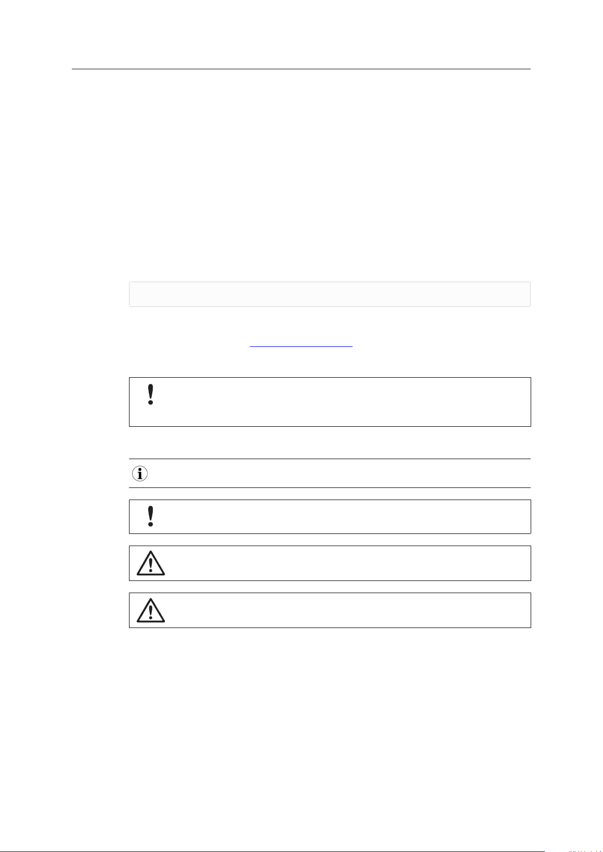
Safety advice is structured as follows:
Cause of the hazard!
Consequences of not taking remediate action.
How to avoid the hazard.
Safety signs and signalwords are used dependent on the level of the hazard.
This is additional information which may facilitate installation and/or operation.
This instruction must be followed to avoid a risk of reduced functionality and/or damage
to the equipment, or to avoid a network security risk.
Caution
This instruction must be followed to avoid a risk of personal injury.
WARNING
This instruction must be followed to avoid a risk of death or serious injury.
CAN@net NT User Manual
4.01.0332.20000 1.8 en-US
Page 7

Safety Instructions 5 (32)
2 Safety Instructions
Risk of interference to radio and television if used in office or home environment!
Use exclusively included accessories. Use exclusively shielded cables.
Make sure that the shield of the interface is connected with the device plug and the plug
on the other side.
Malfunction caused by extension cable!
According to the USB specification connect the interface directly or via an active USB hub
to the computer. Do not use an extension cable.
2.1 General Safety Instructions
► Protect product from moisture and humidity.
► Protect product from too high or too low temperature (see Technical Data, p. 27).
► Protect product from fire.
► Do not paint the product.
► Do not modify or disassemble the product. Service must be carried out by HMS Industrial
Networks.
► Store products in dry and dust-free place.
2.2 Intended Use
The components are used to connect computer systems to CAN and CAN FD networks and to
connect the networks with each other. They are intended for installation on standard DIN rail.
CAN@net NT User Manual
4.01.0332.20000 1.8 en-US
Page 8

Scope of Delivery 6 (32)
3 Scope of Delivery
Included in scope of delivery:
• CAN@net NT
• 1 x power connector
• 2 x CAN connector (with CAN@net NT 200)
4 x CAN connector (with CAN@net NT 420)
• User Manual CAN@net NT
• Installation Guide VCI Driver
• Mini USB cable
The following is available for download on the CAN@net NT support pages on
www.ixxat.com/support-bridges-gateways:
• CAN-Gateway Configurator
• VCI driver
• User Manual CAN-Gateway Configurator for CAN@net NT and CANbridge NT
• Software Design Guide CAN@net NT 100/200/420 Generic Protocol for Gateway Mode
• User Manual CAN@net NT/CANbridge NT Lua ADK
• User Manual CAN@net NT C-API ixcan
CAN@net NT User Manual
4.01.0332.20000 1.8 en-US
Page 9

Product Description 7 (32)
4 Product Description
To use all features the latest version of the CAN-Gateway Configurator as well as the latest firmware of
the CAN@net NT must be installed. For documentation of firmware versions below V6 contact Ixxat
support.
The CAN@net NT hardware provides connectivity to Ethernet and CAN networks with various
operational modes. The CAN@net NT 420 additionally is capable of CAN FD. The application
firmware provides functions to access a CAN bus from virtually every Ethernet TCP/IP host. The
CAN@net NT provides message filtering, based on CAN identifiers, for Bridge and Gateway mode
in the direction from CAN system to TCP/IP network. In the Gateway mode the filter can be
configured by ASCII commands. In the Bridge mode the configuration tool is used to configure
the filter. With the VCI driver the CAN@net NT can be used as a PC interface.
4.1 Features
• CAN@net NT 100: 1 x CAN connections (D-Sub 9 connector)
• CAN@net NT 200: 2 x CAN connections (terminal adapters)
• CAN@net NT 420: 4 x CAN connections (terminal adapters), via the CAN-Gateway
Configurator two connections can be switched between Classic CAN and CAN FD
• 1 x RJ45 Ethernet port, 10/100 Mbit/s
• 1 x mini USB 2.0 port, high-speed
• CAN/CAN FD according to ISO 11898-1:2015
• CAN high speed according to ISO 11898-2:2016
• configuration via USB or Ethernet
• platform independent due to ASCII protocol
• With the CAN-Gateway Configurator a configuration can be created, modified, written to
and read from the target device via USB or Ethernet connection.
The configuration of the following features are described in detail in the User Manual CAN-
Gateway Configurator CANbridge NT & CAN@net NT 100/200/420:
• Classic CAN/CAN FD ID filtering (mapping)
• Classic CAN to CAN FD mapping and CAN FD to Classic CAN mapping (with NT 420)
• J1939 mapping
• cyclic transmission of CAN messages
• MQTT and syslog functionality
• command line program CANGWfile (available for Windows and Linux)
• action rules via if-this-action-then-that-event functionality
• remote access via ASCII protocol
CAN@net NT User Manual
4.01.0332.20000 1.8 en-US
Page 10
Product Description 8 (32)
CAN@net NT
(Gateway)
Host System
1
4
3
2
CAN
CAN or CAN-FD
1+2:
3+4:
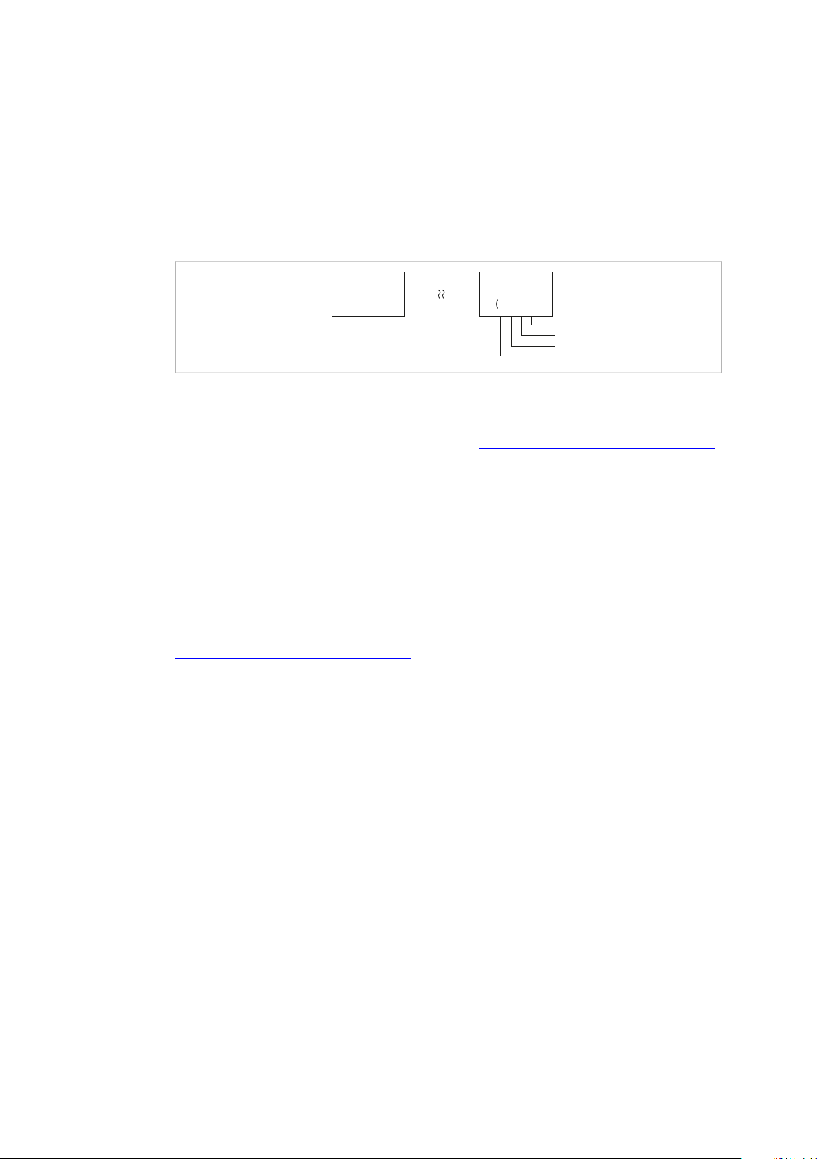
4.2 Operational Modes
4.2.1 ASCII Gateway Mode
In the Gateway mode, the CAN@net NT is hooked to the local intranet or internet (firewall
needed). This allows a TCP/IP host within the reach of this intranet or internet to connect to the
CAN@net NT and gain control of the CAN system. The Ethernet TCP/IP host can exchange
commands and CAN messages using the ASCII protocol. The server relays the commands and
messages to the CAN bus and vice versa.
Fig. 1 Gateway mode
For information about the communication in Gateway mode and commands that are used to
exchange CAN messages see Software Design Guide CAN@net NT 100/200/420 Generic Protocol
for Gateway Mode on CAN@net NT support pages on www.ixxat.com/support-bridges-gateways.
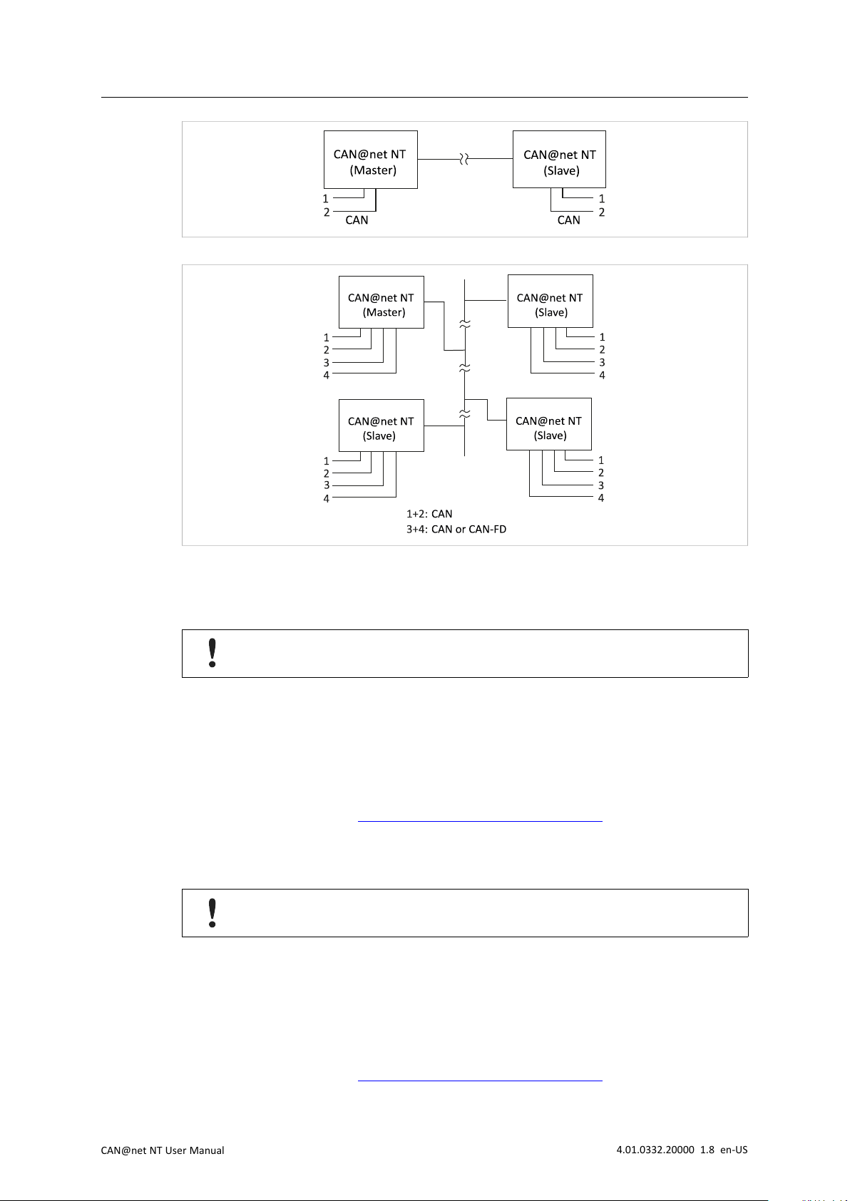
4.2.2 Bridge Modes
A single device can be used as Local CAN Bridge, which allows to map individual messages from
and to each CAN port of the device. The CAN-Ethernet-CAN Bridge mode allows to connect CAN
systems over an Ethernet TCP/IP network, for example the local intranet or the internet (firewall
needed). Minimum two devices are required for a CAN-Ethernet-CAN Bridge. One must be
configured as master and one as slave.
For detailed descriptions of the features in the different modes (e.g. MQTT, Action Rules, cyclic
transmission) and information about the configuration see User Manual CAN-Gateway
Configurator CANbridge NT & CAN@net NT 100/200/420 on the support pages on
www.ixxat.com/support-bridges-gateways.
Possible Bridge Modes with CAN@net NT 100:
• Local CAN Bridge
• CAN-Ethernet-CAN Bridge with 2 devices
Possible Bridge Modes with CAN@net NT 200:
• Local CAN Bridge
• CAN-Ethernet-CAN Bridge with 2 devices
Possible Bridge Modes with CAN@net NT 420:
• Local CAN Bridge
• CAN-Ethernet-CAN Bridge with 2 devices
• CAN-Ethernet-CAN Bridge with 3 devices
• CAN-Ethernet-CAN Bridge with 4 devices
CAN@net NT User Manual
4.01.0332.20000 1.8 en-US
Page 11
Product Description 9 (32)
CAN
CAN@net NT
(Slave)
CAN@net NT
(Master)
2
1
2
CAN
CAN
CAN@net NT
(Slave)
CAN@net NT
(Master)
CAN or CAN-FD
1
4
3
2
1+2:
3+4:
1
4
3
2
CAN@net NT
(Slave)
1
4
3
2
CAN@net NT
(Slave)
1
4
3
2
Fig. 2 CAN-Ethernet-CAN Bridge with 2 devices (NT 200)
Fig. 3 CAN-Ethernet-CAN Bridge with 4 devices (NT 420)
4.2.3 VCI Interface Mode
The VCI interface mode is only possible via Ethernet.
With the VCI driver the CAN@net NT can be used as a PC interface with Windows. All VCI-based
Ixxat tools as well as customer-specific applications based on the VCI driver can be used. The VCI
driver offers the possibility to communicate with up to 128 CAN@net NT devices via LAN or
internet. The CAN@net NT 420 additionally is capable of CAN FD.
For information about the communication in the VCI mode and commands that are used to
exchange CAN messages see Software Design Guides in the VCI download package (available on
the product support pages on www.ixxat.com/support-bridges-gateways).
4.2.4 ECI Interface Mode
The ECI interface mode is only possible via Ethernet.
With the ECI driver the CAN@net NT can be used as a PC interface with Linux. All ECI-based Ixxat
tools as well as customer-specific applications based on the ECI driver can be used. The ECI driver
offers the possibility to communicate with up to 32 CAN@net NT devices via LAN or internet. The
CAN@net NT 420 additionally is capable of CAN FD.
For information about the communication in the ECI mode and commands that are used to
exchange CAN messages see Software Design Guides in the ECI download package (available on
the product support pages on www.ixxat.com/support-bridges-gateways).
CAN@net NT User Manual
4.01.0332.20000 1.8 en-US
Page 12

Product Description 10 (32)
4.3 Add-Ons for Customer Specific Expansions
4.3.1 Lua ADK
With the Lua Application Development Kit customer specific Lua scripts can be executed on the
CAN@net NTin operational modes Local Bridge or CAN-Eth-CAN bridge. By using the Lua ADK for
handling and processing of communication data the functionality of the standard application can
be expanded.
For more information about the Lua ADK see User Manual CAN@net NT/CANbridge NT Lua ADK
on the product support pages on www.ixxat.com/support-bridges-gateways.
4.3.2 C-API ixcan
The CAN API for C uses the ASCII protocol interface to access the CAN@net NT. The C-API ixcan
converts the API calls into corresponding ASCII commands according to the ASCII Gateway Mode
of the CAN@net NT. With the application that uses the C-API ixcan the CAN@net NT can be
accessed exclusively or in shared access with a Bridge configuration.
For more information about the C-API ixcan see User Manual CAN@net NT C-API ixcan on the
product support pages on www.ixxat.com/support-bridges-gateways.
CAN@net NT User Manual
4.01.0332.20000 1.8 en-US
Page 13

Installation 11 (32)
3
1
2
4 5
5 Installation
5.1 Installing the Software
To create a configuration for the CAN@net NT, the CAN-Gateway Configurator running on a
Windows system and the Ixxat VCI driver are needed.
The VCI driver is constantly improved and expanded! Check if a newer version is available within the
product support pages on www.ixxat.com/support.
The CAN-Gateway Configurator is constantly improved and expanded! Check if a newer version is
available within the product support pages on www.ixxat.com/support-bridges-gateways.
► Install the latest VCI driver on a Windows computer (see Installation Guide VCI Driver).
► Download the CAN-Gateway Configurator CANbridge NT & CAN@net NT 100/200/420
package from the product support pages on www.ixxat.com/support-bridges-gateways.
→ By default the package is stored in C:\Program Files\HMS\Ixxat CANGWconfig.
► Start the Ixxat CanGWconfig Setup.
→ Installation wizard starts automatically.
► Follow the instructions in installation program.
► In Windows Start menu open folder Ixxat CANGWconfig and start CAN-Gateway
Configurator V6.
5.2 Installing the Hardware
Fig. 4 Connectors
The CAN@net NT 100 has one D-Sub 9 CAN connector on the front.
1
CAN 1 (CAN@net NT 200/420)
2
CAN 2 (CAN@net NT 200/420)
3 Power connector
4
CAN 3 (CAN@net NT 420)
5
CAN 4 (CAN@net NT 420)
► Make sure that the cross-sectional area of the cable is larger than or equal to 0.14 mm2resp.
25 AWG.
► To remove the connector, use screwdriver or similar tool.
CAN@net NT User Manual
4.01.0332.20000 1.8 en-US
Page 14

Installation 12 (32)
► Connect the CAN cables.
► Connect the power supply.
► Plug the connector into the housing.
The shield of the CAN connector is connected to the device ground and the PE on the back of the
device (DIN rail) via a 1 MΩ resistor and a 10 nF capacitor. To achieve highest interference
immunity, ground the shield of the CAN cable.
5.2.1 Power Connector
Pin Allocation
Pin no.
1
2 V-
3
4
Signal
V+ (+9 V to +36 V DC)
—
—
5.2.2 CAN and CAN FD Connectors
Pin Allocation of Terminal Adapters
Pin no.
1
2
3 CAN GND
4
Signal
CAN high
CAN low
Shield
If a D-Sub 9 connector is used for the terminal adapters, observe the pin allocation of the D-Sub
9 connector.
Pin Allocation of D-Sub 9 Connector (CAN@net NT 100 and Adapter)
Pin no. Signal
1
2
3 CAN GND
4
5
6
7
8
9
—
CAN low
—
Shield
—
CAN high
—
—
CAN@net NT User Manual
4.01.0332.20000 1.8 en-US
Page 15

Installation 13 (32)
5.3 Checking and Updating the Firmware
5.3.1 Checking the Device Firmware
► Make sure, that the latest VCI driver is installed.
► Make sure, that the device is correctly connected to the host computer and to power supply.
► Make sure that the latest CAN-Gateway Configurator is installed (check within product
support pages on www.ixxat.com/support-bridges-gateways).
► Start the Ixxat CAN-Gateway Configurator.
► Open menu Scan and select All Ixxat devices.
→ Connected devices and firmware version of the devices are shown.
5.3.2 Updating the Device Firmware
Whether updating is permitted via Ethernet or a password is needed, is defined in the
security settings of the CAN-Gateway Configurator. The default password is IXXAT. For
more information see user manual CAN-Gateway Configurator.
The firmware is constantly improved and expanded! Check if a newer firmware version is available
within the product support pages on www.ixxat.com/support-bridges-gateways.
To use all features the latest firmware versions of the CAN-Gateway Configurator and of the
CAN@net NT must be installed.
If the current firmware of the CAN@net NT in use is V4 or older:
► See update package on the product support pages on
www.ixxat.com/support-bridges-gateways for information about updating to V5 or contact
Ixxat support.
If the current firmware of the CAN@net NT in use is V5 or V6:
► Check if newer firmware is available on the product support pages on
www.ixxat.com/support-bridges-gateways.
► Download and unzip the update package.
► Make sure, that the device is connected to power supply.
► Connect the device to the computer via USB.
► Make sure that the latest CAN-Gateway Configurator is installed (check within product
support pages on www.ixxat.com/support-bridges-gateways).
► Start the CAN-Gateway Configurator.
► In drop down list Select device type select the device in use.
► In drop down list Select device version select the current firmware version of the device V5
or V6.
► Scan for devices with button Scan and select the device in use in the combo box Target
Device.
► Click button Connect
CAN@net NT User Manual
The device is only found if the selected firmware version matches the firmware version of
the connected device.
.
4.01.0332.20000 1.8 en-US
Page 16

Installation 14 (32)
► Open menu Target and select Read configuration from target.
► Save the configuration on the computer.
► Open menu Target and select Update Firmware.
► Select the update file.
→ Firmware of the connected device is updated.
► In the status window check if the update is completed successfully.
► If the device was updated from V5 to V6 , select V6 in drop-down list Select device version.
► If using a V5 configuration, open menu File and select Convert V5 to V6 to convert the
configuration to the latest version.
► Write the saved configuration to the device.
HMS recommends to verify configurations that are converted from V5 to V6, to make sure that all
settings are working correctly.
CAN@net NT User Manual
4.01.0332.20000 1.8 en-US
Page 17

Configuration 15 (32)
PC
10.41.18.3
CAN@net N T
169.254.163.109
CAN@net N T
192.168.1.23
CAN@net N T
10.41.18.10
CAN@net N T
10.41.18.5
CAN@net N T
a.b.c.d
Router
USB
10.41.18.1
192.168.1.1
1
2
3
4
ETH
6 Configuration
The security settings set via the CAN-Gateway Configurator define if changing the
configuration via Ethernet is possible and if a password is needed to change to
configuration. The default password is IXXAT. For more information see user manual
CAN-Gateway Configurator.
6.1 Connecting Possibilities
There are different possibilities to connect the CAN@net NT. Depending on the type of
connection different ways of configuring the IP address and the device are necessary.
Fig. 5 Types of connection
The following ways of connecting the devices for the configuration are possible:
• (1) via USB (recommended for the first configuration of the device)
• (2) via Ethernet in a local network
• (3) via Ethernet in a local network with an unknown or invalid IP address
• (4) via Router (IP address of device has to be known)
Malfunction caused by extension cable!
According to the USB specification connect the interface directly or via an active USB hub
to the computer. Do not use an extension cable.
CAN@net NT User Manual
4.01.0332.20000 1.8 en-US
Page 18

Configuration 16 (32)
3 4 5 6 7 8 9 10 1 1 122
1
13 14
6.2 Basic Configuration
It is possible to add information about the configuration in fields Author, Configuration Name and
Additional Info in the configuration tree entry Info.
It is possible to create and save a configuration without a connected device. Saved configurations can be
downloaded to connected CAN NT devices with Windows and Linux by using the Command Line Tool (see
Downloading the Configuration with Linux, p. 22).
Fig. 6 CAN-Gateway Configurator
1
Information about target device (STS reflects Power LED of device)
2
Drop-down list Select device type
3
Drop-down list Select device version
4
Drop-down list Select operational mode
5 Button New
6 Button Open
7 Button Save
8 Button Save as
9
Button Verify
10 Button Scan
11
Combo box Target device
12 Button Connect
13
Button Write to
14
Button Read from
6.2.1 Connecting the Device in the CAN-Gateway Configurator
The different CAN@net NT types 100, 200 and 420 can not be combined. For CANEthernet-CAN Bridges use either NT 100 devices, NT 200 devices, or NT 420 devices.
To use all features the latest firmware versions of the CAN-Gateway Configurator and the
CAN@net NT must be installed.
► Make sure, that the latest VCI driver is installed.
► Make sure, that the device is installed correctly (see Installing the Hardware, p. 11).
► Connect a device to the host computer (see Connecting Possibilities, p. 15).
► Make sure, that the latest firmware is on the device (see Checking and Updating the
Firmware, p. 13).
► Make sure, that the latest CAN-Gateway Configurator is installed (check within product
support pages on www.ixxat.com/support-bridges-gateways).
► Start the CAN-Gateway Configurator.
CAN@net NT User Manual
4.01.0332.20000 1.8 en-US
Page 19

Configuration 17 (32)
► To identify the connected devices and the firmware version, open menu Scan and select All
Ixxat devices.
→ Connected devices and firmware version of the devices are shown.
→ Devices that are connected via a router are not found. IP address and device firmware
version must be known.
→ Devices with an unknown or invalid IP address are not found (for more information see
Scanning for Devices with Unknown IP Addresses, p. 18).
► If the connected device is not found, see Scanning for Devices with Unknown IP Addresses, p.
18 for more information.
► Select the type of CAN@net NT in use in drop-down list Select device type (2).
► Select the firmware version of the device in drop-down list Select device version (3).
► Select the desired operational mode for the device in use in drop-down list Select
operational mode (4).
► Click button Scan (10) and select the device in use in combo box Target Device (11).
or
If the device is connected via a router, enter the IP address (see Default Network Settings, p.
27) in combo box Target Device (11).
► Click button Connect (12) to connect the selected device.
► For ASCII Gateway and VCI Interface mode make sure that the IP address is in the range of
the network in which the device is integrated (see Changing IP Address and Device Name, p.
19).
► For CAN-Ethernet-CAN bridge make sure that the IP addresses of all devices of the bridge
are in the same IP range (see Changing IP Address and Device Name, p. 19).
► To create a new project file, click button New (5).
or
To change an existing configuration, click button Read from (14) and save the configuration.
► Configure the device in the selected mode (see Configuration of Interface Modes (ASCII, VCI,
ECI), p. 20 or Configuration of Bridge Modes (Local CAN, CAN-Eth-CAN), p. 21).
CAN@net NT User Manual
4.01.0332.20000 1.8 en-US
Page 20

Configuration 18 (32)
6.2.2 Scanning for Devices with Unknown IP Addresses
If the IP address of a device that is connected via Ethernet is unknown or invalid in the local
network, the device can be found via menu Scan — IP configuration.
Device is only found by scanning, if correct device type and firmware version are selected.
Make sure, that device type and firmware version are selected according to the
connected device.
HMS Industrial Networksrecommends to use a static IP address.
► Select the type of CAN@net NT in use in drop-down list Select device type (2).
► Select the firmware version of the device in drop-down list Select device version (3).
► Open menu Scan and select IP configuration.
→ CAN-Gateway Configurator scans automatically for connected devices of predefined
type and firmware version.
→ Connected devices of the selected type and firmware version are shown.
Fig. 7 IP configuration
► Select the desired device in the drop-down list Target device.
► If necessary define a new IP address.
► Make sure that the IP address is in the range of the network in which the device is
integrated.
► Define the network settings.
► Enter password (default: IXXAT) in field Device password.
► To write the new IP configuration to the target device click button Save.
► Connect the device in CAN-Gateway Configurator (see Connecting the Device in the CAN-
Gateway Configurator, p. 16).
CAN@net NT User Manual
4.01.0332.20000 1.8 en-US
Page 21

Configuration 19 (32)
6.2.3 Changing IP Address and Device Name
HMS Industrial Networks recommends to use a static IP address.
► Make sure that the device is connected in the CAN-Gateway Configurator (see Connecting
the Device in the CAN-Gateway Configurator, p. 16).
► Open menu Target and select Change IP configuration.
→ Window IP Configuration is opened.
► Make sure that the serial number in drop-down list Target device points to the connected
device.
► To change the IP address, define the network settings.
► To change the device name, enter a new device name in field Device name.
► Enter password (default: IXXAT) in field Device password.
► To write the new IP configuration to the target device click button Save.
► Connect the device again in CAN-Gateway Configurator (see Connecting the Device in the
CAN-Gateway Configurator, p. 16).
HMS Industrial Networks recommends to change the default password. See User Manual CAN-Gateway
Configurator for more information.
CAN@net NT User Manual
4.01.0332.20000 1.8 en-US
Page 22

Configuration 20 (32)
6.3 Configuration of Interface Modes (ASCII, VCI, ECI)
The VCI interface mode can only be operated via Ethernet. Configuration is possible via
USB.
Fig. 8 ASCII Gateway Mode
► Make sure, that the device is connected to the network (see Connecting Possibilities, p. 15)
and to the CAN-Gateway Configurator (see Connecting the Device in the CAN-Gateway
Configurator, p. 16).
► In drop-down list (1) select the desired interface operational mode.
► In the configuration tree (5) select Interface.
► If checkbox Only for specified device (6) is enabled, enter the serial number of the device to
which the configuration can be written.
If ASCII Gateway Mode is selected:
► Configure the protocol line ending (4).
► Define the IP port (4).
► If checkbox Expert Mode (7) is enabled, select the desired settings (for more
information see User Manual CAN-Gateway Configurator).
► To write the configuration to the device, click button Write to (3).
or
► Click button Save or Save as (2) to save the configuration.
► To exchange messages in the Gateway mode, use ASCII commands (for more information
see Software Design Guide CAN@net NT 100/200/420 Generic Protocol for Gateway Mode
on product support pages on www.ixxat.com/support-bridges-gateways).
► In the VCI interface mode configure the Device Server (for more information see Installation
Guide VCI Driver included in VCI download package on
www.ixxat.com/support-bridges-gateways.
► In the ECI interface mode see Software Design Guides in the ECI download package
(included in ECI download package on www.ixxat.com/support-bridges-gateways) for
information about the communication in the ECI mode and commands that are used to
exchange CAN messages.
CAN@net NT User Manual
4.01.0332.20000 1.8 en-US
Page 23

Configuration 21 (32)
6.4 Configuration of Bridge Modes (Local CAN, CAN-Eth-CAN)
In the CAN-Ethernet-CAN Bridge mode each device can be configured differently. But to build a Bridge
configuration all devices must be configured in one configuration file. The configuration has to be set
completely for all devices (Master, Slave 1 to 3) and then the complete configuration has to be
downloaded to each device. In the Local CAN Bridge mode only one device is connected and has to be
configured.
Exclusively one master device is allowed in the Bridge mode.
Fig. 9 CAN-Gateway Configurator CAN@net NT 420
For more information about the setting possibilities (e.g. general settings, baud rate, MQTT) and
descriptions of the further configuration possibilities (e.g. J1939 Mapping, cyclic transmission)
see User Manual CAN-Gateway Configurator on www.ixxat.com/support-bridges-gateways.
► Make sure, that the Master device is connected to the network (see Connecting Possibilities,
p. 15) and to the CAN-Gateway Configurator (see Connecting the Device in the CANGateway Configurator, p. 16).
► In drop-down list (1) select the desired bridge operational mode.
CAN@net NT User Manual
4.01.0332.20000 1.8 en-US
Page 24

Configuration 22 (32)
► Configure the following for the Master and for each Slave in use:
► In the configuration tree select General (8) and enter the IP address of the device for
CAN-Ethernet-CAN bridges (4).
► Define the general settings (5).
► In the configuration tree select CAN Ports (8) and configure the baud rate settings for
all ports in use (6).
► Configure further settings if desired (MQTT, Syslog, Action Rules, etc.) (8).
► Configure the mapping table (7).
Only messages that are entered in the mapping table are forwarded. By default, no filter
is set and all messages are rejected.
► To write the configuration to the device, click button Write to (3).
or
► Click button Save or Save as (2) to save the configuration.
► For the CAN-Ethernet-CAN Bridge connect the devices one after another and download the
configuration to each device.
► Observe that for the configuration of a CAN-Ethernet-CAN Bridge each device must be
configured with the same configuration file. If the configuration is changed, the new
configuration file has to be downloaded again to all devices.
6.5 Downloading the Configuration with Linux
The basic configurations, like the selection of the operating mode, can only be created with the
CAN-Gateway Configurator with Windows. A configuration can be created and saved without a
connected device and can then be downloaded to connected CAN NT devices with Linux by using
the Command Line Tool that is included in the scope of delivery.
► To be able to read and write configurations on CAN NT devices, copy the included file
60-bgi.rules to the folder /etc/udev/rules.d/ (root access required).
► To activate the new rules, execute the following command:
udevadm control - -reload-rules
► To download a saved configuration file to CAN NT devices, start the Command Line Tool
cangwfile without parameters.
→ Output shows the syntax, examples and all possible commands.
► Write the configuration to the target device (see User Manual CAN-Gateway Configurator
for more information about the Command Line Tool).
CAN@net NT User Manual
4.01.0332.20000 1.8 en-US
Page 25

Configuration 23 (32)
6.6 Reset to Factory Settings
It is possible to reset the configuration of a connected device to factory settings.
Fig. 10 Menu Reset to factory settings
► Make sure that the device is connected via USB.
► Open menu Target and select Reset to Factory Settings.
► Click button Yes to confirm the reset.
6.7 Read and erase LOG File
In case of an error the device writes the error in a log file. The log file can be read from the
device, saved as a txt file and send to the Ixxat support if needed.
► Open menu Target and select Read and erase LOG file.
→ Window Save Log File As is opened.
► Define a file name and save the file.
→ .txt-file is created and saved.
→ Configuration file is saved.
CAN@net NT User Manual
4.01.0332.20000 1.8 en-US
Page 26

Operation
1452
3
9
8 7
610
7 Operation
Fig. 11 Ports and LEDs
1 Status LED
2 Power LED
3 Mini USB port
4 CAN LEDs 1 to 4
5 User LED
6
Ethernet LED
7
Link speed LED
8
Ethernet port
9
Link/Activity LED
10
CAN connector D-Sub 9 (CAN@net NT 100)
24 (32)
7.1 Ethernet Port
Designed as standard RJ45 port with pin allocation according to Ethernet standard. Because of
the Ethernet PHY auto-crossover feature the device can be connected with a crossover cable or
with a one-to-one network cable.
The shield of the port is connected to the ground of the printed board via a 1 nF capacitor.
Pin Allocation Ethernet Port
Pin no.
1 TX+
2 TX-
3 RX+
4
5
6 RX-
7
8
7.2 Mini USB Port
Provided to connect the device for configuration.
Signal
Connected to pin 5
Connected to pin 4
Connected to pin 8
Connected to pin 7
CAN@net NT User Manual
4.01.0332.20000 1.8 en-US
Page 27

Operation
7.3 Indicators
7.3.1 Power LED
Indicates the status of the power supply.
25 (32)
LED state
Off
Green Power
7.3.2 Status LED
Indicates the device status.
LED state
Off Device not ready No firmware, application firmware not started
Green flashing (1 Hz) Application firmware started Device in Operational state
Red/green flashing
Green/orange flashing
Orange flashing (1 Hz) Automatic baud rate detection or
Red flashing
7.3.3 User LED
Indicates the primary application status and is different, depending on the operating mode.
Description
No power
Description
Configuration file error Rewriting of configuration to device necessary
Device in Configuring state
Lua ADK in remote mode
Device error
Comments
Possible causes: device not connected to power supply,
fuse of device damaged, internal power supply
damaged, power supply not sufficient
Device fully functional
Comments
—
Ongoing automatic baud rate detection, or Lua ADK in
remote mode
Application signals a device error, error in configuration
or no configuration. Read log file for more information
(see Read and erase LOG File, p. 23).
Bridge
In the Bridge mode the User LED can be configured with user defined settings via Action Rules.
See User Manual CAN-Gateway Configurator for more information.
VCI Interface
The User LED is not used.
ASCII Gateway
LED state
Orange/Green flashing
Green flashing Connection monitoring activated Heartbeat mechanism to monitor the connection (PING
7.3.4 Ethernet LED
Indicates the Ethernet communication status.
LED state
Off No Ethernet communication Possible causes: device unsuccessfully initialized, device
Green flashing
Orange flashing
Description
No connection monitoring
Description
TCP/IP packet transmitted
successfully
TCP/IP packet not transmitted
TCP/IP congestion
Comments
—
REQUEST, PING RESPONSE)
Comments
not connected to Ethernet or no communication
Communication was successful
Bad or slow TCP/IP connection, messages can not be
transmitted to CAN and are jammed
CAN@net NT User Manual
4.01.0332.20000 1.8 en-US
Page 28

Operation
7.3.5 Link Speed LED
The yellow LED indicates the link speed.
26 (32)
LED state
Off
Orange
7.3.6 Link/Activity LED
Indicates connection status of the Ethernet interface.
LED state
Off No link detected No connection to Ethernet network, Network cable
Green
Green flashing
7.3.7 CAN LED
CAN 1-4 LEDs indicate the status of the corresponding CAN interface.
LED state
Off
Orange flashing Indicates a state of the automatic
Green flashing
Green CAN communication
Red flashing
Red Bus off CAN controller is in Bus Off state, no CAN
Description
10 MBit/s
100 MBit/s
Description
Link Ethernet connection established, no communication
Activity
Description
No CAN communication No connection to CAN
baud rate detection
CAN communication
CAN communication, CAN
controller in Error state
Comments
damaged
present
Ethernet connection established, communication
present
Comments
See User Manual CAN Gateway Configurator
LED is triggered with each CAN message
Device in Operational state, no messages on CAN bus
CAN controller in Error Warning or Error Passive state,
reception/transmission of CAN messages possible
communication possible
CAN@net NT User Manual
4.01.0332.20000 1.8 en-US
Page 29

Default Network Settings 27 (32)
8 Default Network Settings
Network parameter Default setting Remark
IP Mode
IP Address
Subnet Mask
Standard Gateway
Device Name CAN@net NT
Device password
Static
169.254.y.x
y = ((device serial number - 800 000) DIV 254) MOD 256
x = ((device serial number - 800 000) MOD 254) +1
255.255.0.0
0.0.0.0
IXXAT
Like APIPA if no DHCP server is
available. By scanning the
network, all available devices
can be found.
Transmitted MD5-encrypted
9 Default TCP/UDP Ports
CAN@net PC
CAN Gateway Configurator Device scan and IP configuration:
VCI
Gateway (ASCII Interface)
Bridge (CAN-Ethernet-CAN)
15000/udp
Device configuration (via TCP):
19229/tcp
19229/tcp 1024-65535/tcp
19228/tcp 1024-65535/tcp
Slave: 19239/tcp
Master: 1024-65535/tcp
Device scan and IP configuration:
15001/udp
Device configuration (via TCP):
1024-65535/tcp
—
10 Technical Data
Ethernet Interface
Dimensions 114.5 x 99 x 22.5 mm
Weight
Operating temperature -40 °C to +85 °C
Storage temperature
Power supply 9 V to 36 V DC with overvoltage and polarity protection
Current consumption
Housing material Polyamide
Galvanic isolation 1 kV DC for 1 sec
Protection class
CAN transceiver (CAN 1/CAN2)
CAN FD transceiver (CAN3/CAN4 withCAN@net NT 420)
Max. number of bus nodes
CAN bus termination resistor
CAN baud rates Classic CAN: 5 to 1000 kBaud
CAN pass through delay Local CAN Bridge: 15-25 μs
Startup time after power on
Processing time in Bridge mode
Startup time
10/100 MBit/s, twisted pair
Approx. 150 g
-40 °C to +85 °C
Typically 110 mA at 24 V input voltage,
typically 230 mA at 12 V input voltage
IP20
SN65HVD251
MCP2562FDT
120
None
CAN FD: 5 to 8000 kBaud
CAN-Ethernet-CAN Bridge: 4-6 ms
< 1 s
30 000-40 000 msg/s
Firmware v5.1.3: min. 540 ms (configuration size 5 kB),
max. 1080 ms (configuration size 140 kB)
Firmware v6.0.0: min. 250 ms (configuration size 5 kB),
max. 790 ms (configuration size 140 kB)
Ethernet connection might add up to 1–2 seconds
CAN@net NT User Manual
4.01.0332.20000 1.8 en-US
Page 30

Support/Return Hardware
11 Support/Return Hardware
11.1 Support
► To contact support, go to www.ixxat.com/technical-support/contact-technical-support.
► Scroll down and click button mysupport.hms.se to register a support case.
11.2 Return Hardware
► On www.ixxat.com/support/product-returns click button Portal to access the support portal.
► In the support portal select Submit Product Return (RMA).
► Read the information and click Create RMA Case.
► Register a support account and sign in.
► Fill in the form for warranty claims and repair.
► Print out the Product Return Number (PRN resp. RMA).
► Pack product in a physically- and ESD-safe way, use original packaging if possible.
► Enclose PRN number.
28 (32)
► Observe further notes on www.ixxat.com.
► Return hardware.
12 Disposal
► Dispose of product according to national laws and regulations.
► Observe further notes about disposal of products on www.ixxat.com.
CAN@net NT User Manual
4.01.0332.20000 1.8 en-US
Page 31

Appendix A: Regulatory Compliance 29 (32)
A Regulatory Compliance
A.1 EMC Compliance (CE)
The product is in compliance with the Electromagnetic Compatibility Directive. More information
and the Declaration of Conformity is found at www.ixxat.com.
A.2 FCC Compliance Statement
This device complies with Part 15 of the FCC Rules. Operation is subject to the following two
conditions:
• This device may not cause harmful interference.
• This device must accept any interference received, including interference that may cause
undesired operation.
Product name
Model
Responsible party HMS Industrial Networks Inc
Address 35 E. Wacker Dr, Suite 1700
Phone
Any changes or modifications not expressly approved by HMS Industrial Networks could
void the user's authority to operate the equipment.
This equipment has been tested and found to comply with the limits for a Class B digital
device, pursuant to Part 15 of the FCC rules. These limits are designed to provide
reasonable protection against harmful interference in a residential installation. This
equipment generates, uses and can radiate radio frequency energy and, if not installed
and used in accordance with the instructions, may cause harmful interference to radio
communications. However, there is no guarantee that interference will not occur in a
particular installation. If this equipment does cause harmful interference to radio or
television reception, which can be determined by turning the equipment off and on, the
user is encouraged to try to correct the interference by one or more of the following
measures:
Reorient or relocate the receiving antenna.
Increase the separation between the equipment and the receiver.
Connect the equipment into an outlet on a circuit different from that to which the
receiver is connected.
Consult the dealer or an experienced radio/TV technician for help.
CAN@net NT
100/ 200/420
Chicago , IL 60601
+1 312 829 0601
CAN@net NT User Manual
4.01.0332.20000 1.8 en-US
Page 32

Appendix A: Regulatory Compliance 30 (32)
A.3 Disposal and recycling
You must dispose of this product properly according to local laws and regulations. Because this
product contains electronic components, it must be disposed of separately from household
waste. When this product reaches its end of life, contact local authorities to learn about disposal
and recycling options, or simply drop it off at your local HMS office or return it to HMS.
For more information, see www.hms-networks.com.
CAN@net NT User Manual
4.01.0332.20000 1.8 en-US
Page 33

Appendix B: UL Ordinary Locations (Ord.Loc.) 31 (32)
B UL Ordinary Locations (Ord.Loc.)
CAN@net NT devices are certified for use in ordinary locations in compliance with the following
standard:
• UL 62368-1 & CAN/CSA C22.2 No. 62368-1-14, Audio/video, information and
communication technology equipment Part 1: Safety requirements
The certification number of the certified devices according to OrdLoc certification is:
• E466303
According to the standards listed above, the devices are certified with the following marking:
Intended Use
The components are used to connect computer systems to CAN and CAN FD networks and to
connect the networks with each other. They are intended for installation on standard DIN rail.
Risk of interference to radio and television if used in office or home environment!
Use exclusively included accessories. Use exclusively shielded cables.
Make sure that the shield of the interface is connected with the device plug and the plug
on the other side.
Protect product from moisture and humidity.
Protect product from too high or too low temperature, and from fire.
Utilisation prévue
Les composants sont utilisés pour connecter les systèmes informatiques aux réseaux CAN et CAN
FD et pour connecter les réseaux entre eux. Ils sont destinés à être installés sur un rail DIN
standard.
Risque d’interférence avec la radio et la télévision si elles sont utilisées au bureau ou à la
maison !
Utilisez exclusivement les accessoires inclus. Utilisez exclusivement des câbles blindés.
Vérifiez que le blindage de l’interface est connecté avec la prise de l’appareil et la prise
de l’autre côté.
Protégez le produit de l’humidité.
Le produit ne doit pas être soumis à des températures extrêmes et doit être protégé
contre tout risque d’incendie.
CAN@net NT User Manual
4.01.0332.20000 1.8 en-US
Page 34

last page
© 2020 HMS Industrial Networks
Box 4126
300 04 Halmstad, Sweden
info@hms.se 4.01.0332.20000 1.8 en-US / 2020-12-02 / 20953
 Loading...