

HMS IXXAT Safe T100 Safety Manual–original Instructions
Safety Manual
–
Original Instructions
IXXAT Safe T100
Product
Version
1.x

HMS Technology Center Ravensburg GmbH
Helmut-Vetter-Straße 2
88213 Ravensburg
Germany
Tel.: +49 751 56146-0
Fax: +49 751 56146-29
Internet: www.hms-networks.de
E-Mail: info-ravensburg@hms-networks.de
Support
In case of unsolvable problems with this product please contact HMS in
written form by:
Fax: +49 751 56146-29
E-Mail: support@ixxat.de
Further international support contacts can be found on our webpage
www.ixxat.com/support
Copyright
Duplication (copying, printing, microfilm or other forms) and the electronic
distribution of this document is only allowed with explicit permission of
HMS Technology Center Ravensburg GmbH. HMS Technology Center
Ravensburg GmbH reserves the right to change technical data without
prior announcement. The general business conditions and the regulations
of the license agreement do apply. All rights are reserved.
Registered trademarks
All trademarks mentioned in this document and where applicable third
party registered are absolutely subject to the conditions of each valid
label right and the rights of particular registered proprietor. The absence
of identification of a trademark does not automatically mean that it is not
protected by trademark law.
Document number: 1.04.0300.20000
Version: 3.1
Issue Date: 05.07.2017

Content
Copyright HMS TC Ravensburg GmbH
3
IXXAT Safe T100 Manual, Version 3.1
1 Preface ...................................................................................................... 9
1.1 Important User Information .................................................... 9
1.1.1 T100 safety precautions ......................................................... 10
1.1.2 Liability ................................................................................... 10
1.1.3 Intellectual Property Rights .................................................... 11
1.1.4 Trademark Acknowledgements ............................................. 11
1.2 About This Document ........................................................... 11
1.2.1 Related and Additional Documents ........................................ 12
1.2.2 Document History................................................................... 13
1.2.3 Conventions & Terminology ................................................... 14
1.2.4 Abbreviations ......................................................................... 16
1.3 Restrictions ........................................................................... 18
1.3.1 Handling ................................................................................. 18
1.3.2 Area of Application ................................................................. 18
1.3.3 Validity of this Safety Manual ................................................. 18
1.3.4 Service and Maintenance ...................................................... 19
1.3.5 End of Life .............................................................................. 19
1.3.6 Disclaimer .............................................................................. 19
1.4 Support .................................................................................. 19
1.5 Returning Hardware.............................................................. 20
1.6 CE pre-testing ....................................................................... 21
1.7 Information on EMC .............................................................. 21
1.8 Product change requests ..................................................... 21
2 General Description ............................................................................... 22
2.1 Background ........................................................................... 22
2.2 IXXAT Safe T100 .................................................................... 22
2.3 The Black Channel Approach .............................................. 24
3 T100 operation ....................................................................................... 25
3.1 Overview ................................................................................ 25
3.2 Safety Functions ................................................................... 25
3.3 Pinning .................................................................................. 26
3.4 Power Supply ........................................................................ 28
3.4.1 Voltage Levels and Power Consumption, 24V....................... 28
3.4.2 Reverse Battery Protection, 24V ............................................ 30
3.4.3 EMC Protection, 24V ............................................................. 31

Content
Copyright HMS TC Ravensburg GmbH
4
IXXAT Safe T100 Manual, Version 3.1
3.4.3.1 Clamp Diode ............................................................. 31
3.4.3.2 HF filter ..................................................................... 31
3.4.4 Voltage Levels and Power Consumption, EXT_3V3 ............. 32
3.4.5 Ground Concept ..................................................................... 33
3.4.6 Galvanic isolation ................................................................... 34
3.4.7 Integrated I/O protection circuits ............................................ 34
3.5 Safe Operation ...................................................................... 35
3.5.1 Safe Digital Inputs .................................................................. 35
3.5.1.1 DI-C Contact inputs .................................................. 36
3.5.1.2 DI-S Semiconductor input ........................................ 38
3.5.1.3 Input wiring examples............................................... 38
3.5.1.4 Digital input diagnosis and safe state ....................... 39
3.5.1.5 Safe application DI reaction time ............................. 39
3.5.1.6 DI diagnostic test interval ......................................... 40
3.5.1.7 Reliability block diagram .......................................... 40
3.5.2 Test Outputs ........................................................................... 42
3.5.3 Safe Digital Outputs ............................................................... 44
3.5.3.1 Digital output diagnosis and DO diagnostic test
interval ...................................................................... 45
3.5.3.2 Loss of ground at DO ............................................... 46
3.5.3.3 Safe application DO reaction time ............................ 46
3.5.4 Output wiring examples ......................................................... 48
3.5.5 Reliability block diagram ........................................................ 49
3.6 Safe State and Reaction times ............................................. 50
3.7 Hardware interfaces to non-safe components .................... 55
3.7.1 T100 Hardware Reset conditions ........................................... 56
3.7.1.1 Powerup Reset ......................................................... 56
3.7.1.2 Restart Reset ........................................................... 57
3.7.2 Wiring example ...................................................................... 58
3.8 T100 Firmware update .......................................................... 59
3.9 T100 Module identification ................................................... 60
3.10 Operating states.................................................................... 61
3.10.1 T100/PS specific states ........................................................ 61
3.10.2 T100/CS specific states ........................................................ 63
4 In-Design ................................................................................................ 65
4.1 Mechanical Specification ..................................................... 65

Content
Copyright HMS TC Ravensburg GmbH
5
IXXAT Safe T100 Manual, Version 3.1
4.1.1 T100 dimensions .................................................................... 65
4.1.2 Connection to host board ....................................................... 65
4.1.3 Mounting recommendations ................................................... 66
4.1.4 Mechanical mounting set recommendations .......................... 66
4.1.5 Clearances ............................................................................. 67
4.1.6 Allowed mounting positions ................................................... 68
4.1.7 Labeling of safety signals ....................................................... 68
4.2 Environmental considerations ............................................. 69
4.2.1 Layout rules ............................................................................ 69
4.2.2 Temperature ........................................................................... 70
4.2.2.1 Temperature verification inside CDev ...................... 70
4.2.3 Shock / Vibration .................................................................... 71
4.2.4 Humidity and Pollution level ................................................... 72
4.2.5 Intrusion protection................................................................. 72
4.2.6 Maximum operation altitude ................................................... 72
4.2.7 EMC ....................................................................................... 73
4.2.7.1 T100 radiated Emission ........................................... 75
5 Configuration and Programming ......................................................... 76
5.1 Configuration of safety inputs ............................................. 77
5.1.1 Enable .................................................................................... 77
5.1.2 Channel Type ......................................................................... 77
5.1.3 Debounce Filter ...................................................................... 78
5.1.4 Channel Mode ........................................................................ 80
5.1.5 Consistency Filter................................................................... 81
5.1.6 Reset of Input Errors .............................................................. 82
5.1.7 Non-safe read access ............................................................ 82
5.2 Configuration of test outputs ............................................... 83
5.3 Configuration of safety outputs ........................................... 85
5.3.1 Channel Mode ........................................................................ 85
5.3.2 Enable .................................................................................... 86
5.3.3 Output test .............................................................................. 86
5.3.4 Reset of Output Errors ........................................................... 88
5.4 Pre-tested configurations .................................................... 89
5.4.1 PROFIsafe configurations ...................................................... 89
5.4.1.1 Dual-Channel DI-C ................................................... 89
5.4.1.2 Dual-Channel DI-S ................................................... 90

Content
Copyright HMS TC Ravensburg GmbH
6
IXXAT Safe T100 Manual, Version 3.1
5.4.1.3 Mixed DI-C Dual/Single Channel ............................ 91
5.4.2 CIP Safety configurations ...................................................... 92
5.4.2.1 Dual-Channel DI-C ................................................... 92
5.4.2.2 Dual-Channel DI-S ................................................... 93
5.4.2.3 Mixed DI-C Dual/Single Channel ............................ 94
6 Safety fieldbus communication ............................................................ 95
6.1 General .................................................................................. 95
6.2 PROFIsafe ............................................................................. 96
6.2.1 PROFIsafe configuration sequence ....................................... 96
6.2.1.1 F-Parameter setup ................................................... 97
6.2.1.1.1 F-Address ............................................... 98
6.2.1.1.2 Watchdog time ........................................ 98
6.2.1.1.3 iParameter CRC ..................................... 98
6.2.1.2 iParameter setup ...................................................... 99
6.2.1.3 GSD file .................................................................. 102
6.2.1.4 iParameter CRC calculation tool ............................ 104
6.2.1.5 T100/PS status information .................................... 104
6.2.2 F-Data exchange.................................................................. 104
6.2.2.1 Input process image ............................................... 105
6.2.2.2 Output process image ............................................ 107
6.2.3 Error Handling ...................................................................... 109
6.2.4 T100/PS temperature sensor data access ........................... 110
6.2.5 Device replacement ............................................................. 110
6.2.6 PROFIsafe certification ........................................................ 111
6.3 CIP Safety ............................................................................ 112
6.3.1 CIP Object Model ................................................................. 112
6.3.1.1 Safety Supervisor Object (0x39) ............................ 112
6.3.1.1.1 Class Attributes .................................... 112
6.3.1.1.2 Instance Attributes ................................ 112
6.3.1.1.3 Services ................................................ 115
6.3.1.2 Safety Validator Object (0x3A) ............................... 115
6.3.1.2.1 Class Attributes .................................... 115
6.3.1.2.2 Instance Attributes ................................ 116
6.3.1.2.3 Services ................................................ 118
6.3.1.3 Safety Discrete Output Point Object (SDOP) (0x3B)119
6.3.1.3.1 Class Attributes .................................... 119

Content
Copyright HMS TC Ravensburg GmbH
7
IXXAT Safe T100 Manual, Version 3.1
6.3.1.3.2 Instance Attributes ................................ 119
6.3.1.3.3 Services ................................................ 120
6.3.1.4 Safety Discrete Input Point Object (SDIP) (0x3D) .. 120
6.3.1.4.1 Class Attributes .................................... 120
6.3.1.4.2 Instance Attributes ................................ 120
6.3.1.4.3 Services ................................................ 120
6.3.1.5 Safety Discrete Input Group Object (SDIG) (0x3E) 121
6.3.1.5.1 Class Attributes .................................... 121
6.3.1.5.2 Instance Attributes ................................ 121
6.3.1.5.3 Services ................................................ 121
6.3.1.6 Safety Dual Channel Output Object (SDCO) (0x3F)122
6.3.1.6.1 Class Attributes .................................... 122
6.3.1.6.2 Instance Attributes ................................ 122
6.3.1.6.3 Services ................................................ 122
6.3.1.7 Diagnostic Object (0x64) ........................................ 123
6.3.1.7.1 Class Attributes .................................... 123
6.3.1.7.2 Instance Attributes ................................ 123
6.3.1.7.3 Services ................................................ 123
6.3.1.8 Failure code object (0x65) ...................................... 124
6.3.1.8.1 Class Attributes .................................... 124
6.3.1.8.2 Instance Attributes ................................ 124
6.3.1.8.3 Services ................................................ 125
6.3.2 CIP Safety configuration sequence ...................................... 126
6.3.2.1 Configuration steps and states ............................... 126
6.3.2.2 Reset services ........................................................ 128
6.3.2.3 Configuration data string ........................................ 129
6.3.2.4 SCID calculation ..................................................... 131
6.3.3 Safety Data exchange .......................................................... 132
6.3.3.1 Safe input data ....................................................... 133
6.3.3.2 Safe output data ..................................................... 135
6.3.4 Error Handling ...................................................................... 136
6.3.4.1 Safe input and output channel error handling ........ 136
6.3.4.2 Event-log ................................................................ 137
6.3.4.3 Fail-safe errors ....................................................... 138
6.3.4.4 Configuration data storage errors .......................... 138
6.3.5 Status and diagnostic information ........................................ 139
6.3.6 Parameters for Connection Establishment .......................... 140

Content
Copyright HMS TC Ravensburg GmbH
8
IXXAT Safe T100 Manual, Version 3.1
6.3.7 LED signaling ....................................................................... 141
6.3.8 Device replacement ............................................................. 141
6.3.9 Requirements for the end user manual ................................ 142
6.3.10 Requirements for the end device (CDev) ........................... 144
6.3.11 CIP Safety certification ....................................................... 145
7 Re-Certification steps .......................................................................... 146
7.1 General CDev integration and re-certification steps ........ 146
8 Characteristics ..................................................................................... 148
9 Compliance .......................................................................................... 150
9.1 CE ........................................................................................ 150
9.2 UL ......................................................................................... 150
9.3 IEC 61508 and EN ISO 13849 .............................................. 150
9.4 Fieldbus compliance .......................................................... 151
9.4.1 PROFIsafe ........................................................................... 151
9.4.2 CIP Safety ............................................................................ 151
9.5 RoHS .................................................................................... 151
9.6 EMC ..................................................................................... 151
Appendix ...................................................................................................... 152
A Safety Integration Rules ...................................................................... 153
B Safety Application Rules ..................................................................... 157
C Applicable Standards .......................................................................... 164
D CIP Safety Event and Error Codes ..................................................... 166
E Declaration of incorporation ............................................................... 174
Preface
Copyright HMS TC Ravensburg GmbH
9
IXXAT Safe T100 Manual, Version 3.1
1 Preface
When to Read and Use the Document
Whether you already have decided to develop an application with the IXXAT
Safe T100 or not, you shall read this document as a first introduction on how
to, as an integrator, make a safe hardware In-Design with the module or, as an
end-user, use the T100 in a safety application. This safety manual also lists
the necessary steps to be followed by the integrator (IDR-x) and the end-user
(SAR-x) in order to get a simplified recertification of the safety functions of the
T100 in a safety host and a safety application.
This document covers the generic implementation and use as well as the
specific integration and use of the T100 running PROFIsafe with an Anybus
CompactCom PROFINET module or CIP Safety with a CompactCom
EtherNet/IP module.
The Anybus CompactCom concept is further described in the Anybus
CompactCom Software Design Guide and the Anybus CompactCom
Hardware Design Guide (see section 1.2.1) which can be found at the support
pages at www.anybus.com.
1.1 Important User Information
This document is intended to provide a good understanding of the generic
properties of the IXXAT Safe T100 (T100). It contains information for the
customer necessary for correct usage of the IXXAT Safe T100 in safety
applications. It gives advice on how to integrate the IXXAT Safe T100 into a
product with the target to get safe inputs and outputs and connect them to a
system using a safety fieldbus such as PROFIsafe or CIP Safety for
communication.
The reader of this document is expected to be familiar with hardware design
and communication systems in general.
Knowledge of functional safety is required for the design, testing and
certification process of the customer device.
Along with the information giving a better understanding of the T100,
this document contains safety relevant advice, that must be followed both by
the integrator and by the end-user. These safety critical aspects are clearly
marked with exclamation signs, .
A full list of all safety advices can be found in appendix A and appendix B.
For more information, documentation etc., please visit the IXXAT web site,
'www.ixxat.com'.
Preface
Copyright HMS TC Ravensburg GmbH
10
IXXAT Safe T100 Manual, Version 3.1
1.1.1 T100 safety precautions
The T100 contains measures against a set of reasonably
foreseeable misuse which is the use of a product, process or
service in a way not intended by the supplier, but which may result
from readily predictable human behavior. In addition the T100 is
also prepared to deal with some malevolent or accidental misuse.
As the end user is connecting sensors and actuators directly to
the T100 there is a direct interaction and therefore a source of
errors to be considered. The failures of IO modules are covered
by measures described below in chapters “Digital Input,
Semiconductor (DI-S)” (section 3.5.1.2), “Digital Input, Contact
(DI-C)” (section 3.5.1.1) and “Digital Output (DO)” (section 3.5.3).
Nevertheless, the Integrator and the end user has to think about
all reasonably foreseeable misuse and malevolent or unauthorized
actions that may result in his applications and check if the
measures of the T100 are strong enough to detect and safely treat
these error sources. [SC_344, SC_381]
1.1.2 Liability
Every care has been taken in the preparation of this manual. Please inform
HMS Industrial Networks AB of any inaccuracies or omissions. The data and
illustrations found in this document are not binding. We, HMS Industrial
Networks AB, reserve the right to modify our products in line with our policy of
continuous product development.
The information in this document is subject to change without notice and
should not be considered as a commitment by HMS Industrial Networks AB.
HMS Industrial Networks AB assumes no responsibility for any errors that may
appear in this document.
There are many applications of this product. Those responsible for the use of
this device must ensure that all the necessary steps have been taken to verify
that the applications meet all performance and safety requirements including
any applicable laws, regulations, codes, and standards.
HMS Industrial Networks AB will under no circumstances assume liability or
responsibility for any problems that may arise as a result from the use of
undocumented features, timing, or functional side effects found outside the
documented scope of this product. The effects caused by any direct or indirect
use of such aspects of the product are undefined, and may include e.g.
compatibility issues and stability issues.
The examples and illustrations in this document are included solely for
illustrative purposes. Because of the many variables and requirements
associated with any particular implementation, HMS Industrial Networks AB
cannot assume responsibility for actual use based on these examples and
illustrations.
Preface
Copyright HMS TC Ravensburg GmbH
11
IXXAT Safe T100 Manual, Version 3.1
HMS will and cannot guarantee backwards compatibility for older applications,
where not all recommendations, presented in the Anybus CompactCom
Hardware Design Guide, have been followed.
1.1.3 Intellectual Property Rights
HMS Industrial Networks AB has intellectual property rights relating to
technology embodied in the product described in this document. These
intellectual property rights may include patents and pending patent
applications in the US and other countries.
1.1.4 Trademark Acknowledgements
Anybus ® is a registered trademark of HMS Industrial Networks AB. All other
trademarks are the property of their respective holders.
Warning: This is a class A product according to DIN EN 55022. In
a domestic environment this product may cause radio interference
in which case the user may be required to take adequate
measures.
ESD Note: This product contains ESD (Electrostatic Discharge)
sensitive parts that may be damaged if ESD control procedures
are not followed. Static control precautions are required when
handling the product. Failure to observe this may cause damage
to the product.
Warning: Improper handling of the T100 by the integrator can
cause damage to the T100 and result in a loss of the safety
functions. The T100 shall only be transported and handled in ESD
protected areas, by specially trained personnel.
1.2 About This Document
For more information, documentation etc., please visit the HMS website,
www.hms-networks.com.

Preface
Copyright HMS TC Ravensburg GmbH
12
IXXAT Safe T100 Manual, Version 3.1
1.2.1 Related and Additional Documents
Document Doc. Id. Author
Anybus CompactCom M40 Hardware Design Guide
HMSI-216-126 HMS
Anybus CompactCom 30 Hardware Design Guide
HMSI-168-31 HMS
Anybus CompactCom 40 Software Design Guide
HMSI-216-125 HMS
Anybus CompactCom 30 Software Design Guide
HMSI-168-97 HMS
Anybus CompactCom 30 PROFINET Network
Interface Appendix
HMSI-168-49 HMS
PROFIsafe Profile Version 2.4
3.192b PNO
Anybus CompactCom 40 PROFINET IRT Network
Guide
SCM-1202023
HMS
Anybus CompactCom 40 Network Guide EtherNet/IP
SCM-1202031
HMS
Anybus Safety Interface Guide
SCM-1202024
HMS
The CIP Networks Library - Volume 5, CIP Safety
Edition 2.14
ODVA
A list of standards, relevant to this product, can be found in appendix C.

Preface
Copyright HMS TC Ravensburg GmbH
13
IXXAT Safe T100 Manual, Version 3.1
1.2.2 Document History
Revision Date Autor(s) Chapter(s)
Description
2.5 2014-12-18 KrS 3.6.2, 9.1,
9.3,
Appendix
B
Integrated Review results of
TÜV, Clarified SAR-5.4.
Official Released document
3.1 2017-07-04 KrS General
Correction in T100/PS state
diagram and clarification of
IDR-4.1. T100/CS with
description of CIP Safety
specific data added.
Preface
Copyright HMS TC Ravensburg GmbH
14
IXXAT Safe T100 Manual, Version 3.1
1.2.3 Conventions & Terminology
The following conventions are used throughout this manual:
• The terms ‘T100’ or ‘module’ refer to the IXXAT Safe T100 in general
which describes the safety-protocol independent properties.
• The term ‘T100/PS’ refers to the IXXAT Safe T100 module running the
PROFIsafe (PS) safety protocol.
• The term ‘T100/CS’ refers to the IXXAT Safe T100 module running the
CIP Safety (CS) safety protocol.
• The terms ‘host’ or ‘host application’ refer to the device that hosts the
IXXAT Safe T100 and the Anybus CompactCom.
Danger - Violation of this precautionary measure leads to severe
injury, death or material-damage.
Warning - Violation of this precautionary measure probably leads
to severe injury, death or material-damage.
Attention - Violation of this precautionary measure probably leads
to minor injury or material-damage.
• The terms ‘user’ or ‘end user’ refers to a person operating or handling
the host to which the T100 is a subpart.
• The term integrator refers to a person, who integrates the T100 into a
host and who is responsible for the safety certification of the entire host.
• In-design rules, marked with [IDR-x], shall be followed by the integrator
when designing or integrating a safety device with the T100.
• Safety application rules marked with [SAR-x], shall be forwarded to the
end user by the integrator within its safety manual. [SAR-x] shall be
followed by the end user when operating the T100 within a safety
application.
• Information necessary for the HMS-internal requirement tracking is
labeled with [PRS_x], [SC_x], [DR_x], [ FWTS_x ] or [HR_x].
• Numbered lists provide sequential steps.
• Bulleted lists provide information, not procedural steps.
• Hexadecimal values are written in the format NNNNh, where NNNN is
the hexadecimal value.
•
This sign is used to mark safety relevant requirements or
information which shall be fulfilled or considered by the host device.

Preface
Copyright HMS TC Ravensburg GmbH
15
IXXAT Safe T100 Manual, Version 3.1
In accordance with the ISO/IEC Directives, Part 2, Fifth Edition, 2004,
the following verbal forms are used in this document with the following
meanings:
- Requirements:
shall is required
shall not is not allowed, is not permitted
-Recommendations:
should is recommended
should not is not recommended
- Permissions:
may is allowed
need not is not required
- Possibility and capability:
can is able, is possible
cannot is not able, is not possible

Preface
Copyright HMS TC Ravensburg GmbH
16
IXXAT Safe T100 Manual, Version 3.1
1.2.4 Abbreviations
Word Explanation
AIC Anybus internal communication (protocol used to communicate
between T100 and non-safe communication controller)
CDev
Customer Device – Device which integrates the T100 to fulfill a
certain safety function
CIP Common Industrial Protocol
CSS CIP Safety Software
DI Digital Input
DI-C Digital Input – Contact
DIH Digital Input High
DIL Digital Input Low
DI-S Digital Input – Semiconductor
DO Digital Output
ESD Electrostatic Discharge
FE Functional Earth
FS Fail-Safe
HFT Hardware Fault Tolerance
I Input
O Output
OCPUNID Output Connection Point Owning UNID
PELV Protected Extra Low Voltage
PL Performance Level
PS PROFIsafe
PSU Power Supply Unit
PWR Power
RPI Requested Packet Interval
SC Safety Controller
SCID Safety Configuration Identifier
SELV Safety Extra Low Voltage
SIL Safety Integrity Level
T100 IXXAT Safe T100 (generic / protocol independent)
T100/CS IXXAT Safe T100 for CIP Safety
T100/PS IXXAT Safe T100 for PROFIsafe
TO Test Output
TUNID Target Unique Network Identifier
UNID Unique Network Identifier

Preface
Copyright HMS TC Ravensburg GmbH
17
IXXAT Safe T100 Manual, Version 3.1
VSS Negative supply voltage; equal to logic ground (GND) potential

Preface
Copyright HMS TC Ravensburg GmbH
18
IXXAT Safe T100 Manual, Version 3.1
1.3 Restrictions
1.3.1 Handling
This safety product shall be handled, operated, and maintained only by
qualified personnel. Qualified personnel in the context of this safety manual
are
• familiar with the basic safety concepts and regulations for safety
and accident prevention.
• experienced in the field of safety applications to recognize or
avoid dangerous situations.
1.3.2 Area of Application
The T100 shall only be used under the mechanical, electrical, and other
environmental conditions described within this safety manual. A proper safe
operation of the device is possible only if all precautions for the T100 are
considered during storage, transport, mounting, operation and maintenance.
Checking if specific safety sector norms are applicable for the use of the T100
shall be carried out by the integrator or end-user.
[IDR-1.1], [SAR-1.1] Warning: The T100 is designed to be used in the
environment of industrial automation or process control systems. The
T100 integrator and end-user shall check if the T100 is allowed to be
used within the environment of the final application.
1.3.3 Validity of this Safety Manual
This safety manual is valid for the following HMS products:
• 1.01.0300.00000, IXXAT Safe T100/PS (Prototype – shall not be used
for safety-related applications)
• 1.01.0300.00001, IXXAT Safe T100/PS Certified Product Version 1.0:
Controller Board V1.3.1
IO-Board V1.3.1
Firmware V0.3.12 (Major SW Version: 0, Minor SW Version: 3, Build: 12)
Bootloader V1.15
• 1.01.0300.00001, IXXAT Safe T100/PS Certified Product Version 1.1:
Controller Board V1.3.1
IO-Board V1.3.1
Firmware V0.3.19 (Major SW Version: 0, Minor SW Version: 3, Build: 19)
Bootloader V1.15
• 1.01.0301.00001, IXXAT Safe T100/CS Certified Product Version 1.0:
Controller Board V1.3.1
IO-Board V1.3.1
Firmware V0.2.5 (Major SW Version: 0, Minor SW Version: 2, Build: 5)
Bootloader V2.0
Preface
Copyright HMS TC Ravensburg GmbH
19
IXXAT Safe T100 Manual, Version 3.1
Other documents related to the integration of the T100 or the Anybus
CompactCom as well as application notes can be found at www.hmsnetworks.com.
1.3.4 Service and Maintenance
The T100 itself does not contain any serviceable parts. Moreover it is not
allowed to modify or repair the T100 in case of a hardware failure.
[IDR-1.2], [SAR-1.2] Danger: No repair or modification of the T100 is
allowed.
[SAR-1.3] Danger: Safety critical T100 failures which do not lead to the
safe state shall be reported to HMS/IXXAT immediately (see section 1.4).
1.3.5 End of Life
The maximum product life time (proof-test interval) of the T100, which allows a
proper operation within the specified safety limits, is 20 years (see section
3.5). Please note the regulations for the disposal of electronic equipment after
product end of life.
1.3.6 Disclaimer
HMS Industrial Networks is not liable and does not provide warranty for
damages caused by
• violation of safety standards and rules
• non-observance of the safety notices described in this safety manual
• any modification to the T100 hardware device
• improper installation or use
1.4 Support
For more information on HMS and IXXAT products, FAQ lists and installation
tips, please refer to the support area on the respective home pages,
(http://www.hms-networks.com, http://www.ixxat.de).
There you will also find information on current product versions and available
updates. For general contact information and where to find support, please
refer to the contact and support pages at
www.hms-networks.com or
www.ixxat.de.

Preface
Copyright HMS TC Ravensburg GmbH
20
IXXAT Safe T100 Manual, Version 3.1
1.5 Returning Hardware
If it is necessary to return hardware, please download the relevant RMA form
from the home page and follow the instructions on this form.

Preface
Copyright HMS TC Ravensburg GmbH
21
IXXAT Safe T100 Manual, Version 3.1
1.6 CE pre-testing
As the T100 is not considered to be a complete device or machine with
respect to the machine directive, a CE compliance declaration is not possible.
Anyway, the T100 was tested in an exemplary safety device to comply with the
CE Rules.
Note: This equipment has been pre-tested and found to comply with the limits
for a Class A digital device in accordance with DIN EN 55022. These limits are
designed to provide reasonable protection against harmful interference when
the equipment is operated in an industrial environment. This equipment
generates, uses, and can radiate radio frequency energy and, if not installed
and used in accordance with the instruction manual, may cause harmful
interference to radio communications. Operation of this equipment in a
residential area is likely to cause harmful interference in which case the user
will be required to correct the interference at his own expense.
1.7 Information on EMC
The product is a class A device (DIN EN 55022) and therefore designed for
the use in industrial environments only. If the product is used in office or home
environment radio interference can occur under certain conditions.
For more details about the EMC-Test applied to the T100 refer to section 4.2.7
of this document.
1.8 Product change requests
Product change requests or any detected product error shall be reported to
HMS using the contact form of the support web page under the URL
www.ixxat.de/support.

General Description
Copyright HMS TC Ravensburg GmbH
22
IXXAT Safe T100 Manual, Version 3.1
2 General Description
2.1 Background
The need for safe transfer of data is steadily rising in large segments of the
industry. Many companies are today looking into integrated safety which
means that the standard non-safe communication network is also used for the
safety-related data exchange. The demand for readymade solutions has
grown, as not all customers have either the means or the time to develop
solutions of their own.
2.2 IXXAT Safe T100
The IXXAT Safe T100 is a pre-certified embedded safety option module which
provides device manufacturers with an easy and cost efficient way to integrate
conformant safe I/O signals into standard automation devices. It connects via
its serial black channel interface to an Anybus CompactCom module. The
module provides digital safe I/O signals, controlled via the network and directly
connected to the safety functions of an automation device.
The black channel is a transportation mechanism for safety related protocol
extensions over a non-safe communication media. The safety layer performs
safety related transmission functions and checks on the communication to
ensure that the integrity of the link meets the requirement for use in a SIL 3
environment.
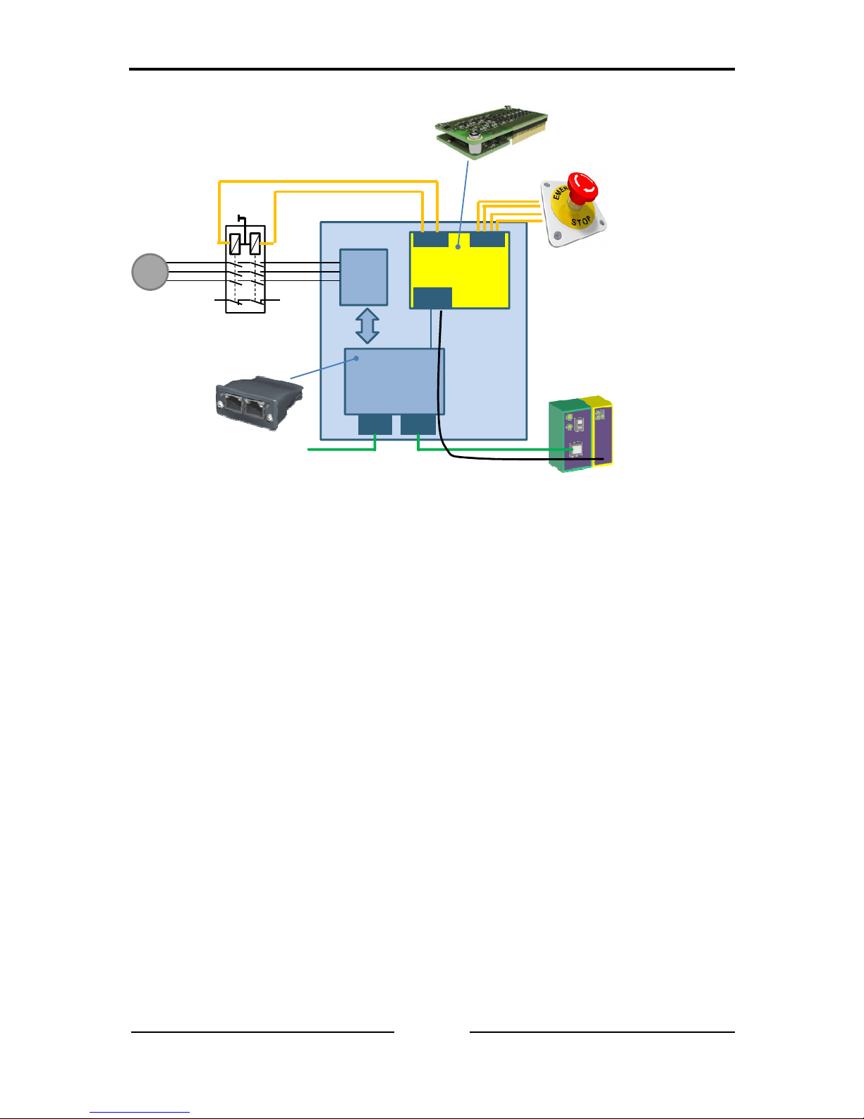
Figure 2-1 shows a typical example of an integrated safety communication
solution. The black channel can be considered as a virtual link between the
safety layers of the devices.
General Description
Copyright HMS TC Ravensburg GmbH
23
IXXAT Safe T100 Manual, Version 3.1
ABCC
Anybus CompactCom
Network interface
module
T100
IXXAT Safe T100
Module
ABCC
I/F
OUT IN
Motor
Control
NW NW
M
Safe PLC
Non-Safe PLC /
Network Master
Industrial network
Emergency Button
Host
Device
Safety relay
Black Channel
Safety protocol transportation
Figure 2-1: Architectural overview of a typical customer safety host device
• Safety: The IXXAT Safe T100 is developed in order to be suitable for
use in applications up to Category 4 / PL e according to EN ISO 138491 and SIL 3 according to EN 62061 / IEC 61508.
• Mechanics: The IXXAT Safe T100 is an add-on PCB connected to the
host device.
• Application: The IXXAT Safe T100 connects inputs and outputs in a safe
way to the communication data bus.
In combination with other safe components and under the described conditions
it is possible to obtain a certificate from a notified body for functional safety
with limited efforts.
Features
• Safe communication protocol execution (e.g. PROFIsafe or CIP Safety)
• Configurable 3 safe dual-channel (up to SIL 3, cat 4/PL e depending on
configuration and external wiring) or 6 safe single-channel inputs (up to
SIL 3, cat 2/PL d – depending on the configuration, external wiring and
components)
• Configurable 1 safe dual-channel output (SIL 3, cat4/PL e, depending on
configuration and external wiring)
• Possibility to connect active and / or passive inputs
• Compact size
General Description
Copyright HMS TC Ravensburg GmbH
24
IXXAT Safe T100 Manual, Version 3.1
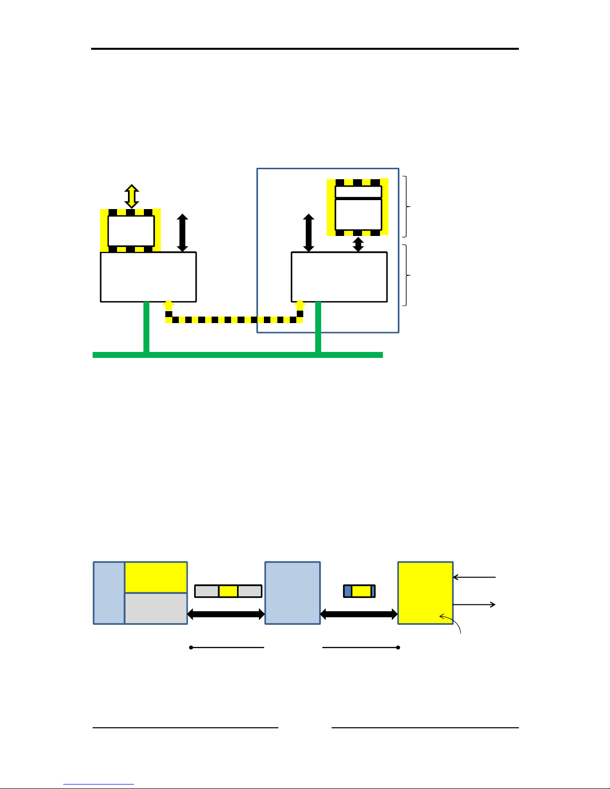
2.3 The Black Channel Approach
It is possible to transmit safety messages on the existing standard bus cables
in coexistence with the standard messages. Conventional and safety
messages can be operated on one single bus cable including the use of
standard PLCs with integrated but logically separated safety processing.
Standard protocol
Safety
layer
Safety PLC
Standard
application
Standard protocol
Safety
layer
Standard
application
Safe I/O
Host device
IXXAT Safe T100
with safe inputs
and safe outputs
Standard Anybus
CompactCommodule
providing a separate
communication channel
for thesafety module
Black Channel
Figure 2-2: Black-channel approach
The safety protocol has no impact on the standard bus protocols. It doesn’t
matter what kind of physical transmission channel is used, nor transmission
rates, nor error detection means. The message is embedded in a safety
message and the safety protocol overtakes, for the users, the safety
assessment of their individual backplane communication and also
transmission paths beyond the original networks. It secures the whole path
from the location where a safety signal originates to the location where it is
processed and vice versa. The transmission channel acts as a Black Channel,
where the user does not have to consider the underlying content.
PLC
Safe PLC
Network
Master
Anybus
standard
comm.
module
IXXAT
Safe T100
module
Network telegram
with safety
container
Internal telegram
with safety
container
Black channel
Safe inputs
Safe outputs
Packing/unpacking
the safety container
Figure 2-3: Safety container encapsulation
T100 operation
Copyright HMS TC Ravensburg GmbH
25
IXXAT Safe T100 Manual, Version 3.1
3 T100 operation
3.1 Overview
The T100 includes all necessary features in soft- and hardware to operate safe
digital inputs and outputs. Beside a detailed FMEDA (Failure Mode Effect and
Diagnosis Analysis) of the hardware during the design phase, a permanent
checking of the digital input and output sections as well as of the processor
units during runtime of the T100 takes place. Any fault detected during runtime
will cause the T100 to enter the fail-safe state.
[SAR-3.1] Attention: There is no galvanic isolation between the digital
inputs, the digital outputs and the T100 board electronic itself.
3.2 Safety Functions
1. The status of the digital inputs (DI-C, DI-S) is reported via a safety
output telegram to the safe communication network. Only if the status of
the input is “active” and no failure in the input circuit has been detected,
the safety telegram to the PLC will report the input data as “active”.
2. The outputs (DO) of the T100 can be controlled via the safety
communication network protocol. Only if the nominal value of the input
telegram (to the T100) is "active" and no failure in the transfer of the
safety telegram from the PLC has been detected, the output (DO) may
be set to active.
3. Any severe fault detected during runtime will cause the T100 to enter the
fail-safe state and to turn off the digital outputs as well as to stop the
communication via the safety fieldbus protocol. In case of channelspecific errors the T100 deactivates the channel, i.e. set the output to
the inactive state or set the status of the input data reported via the
safety fieldbus to inactive.
T100 operation
Copyright HMS TC Ravensburg GmbH
26
IXXAT Safe T100 Manual, Version 3.1
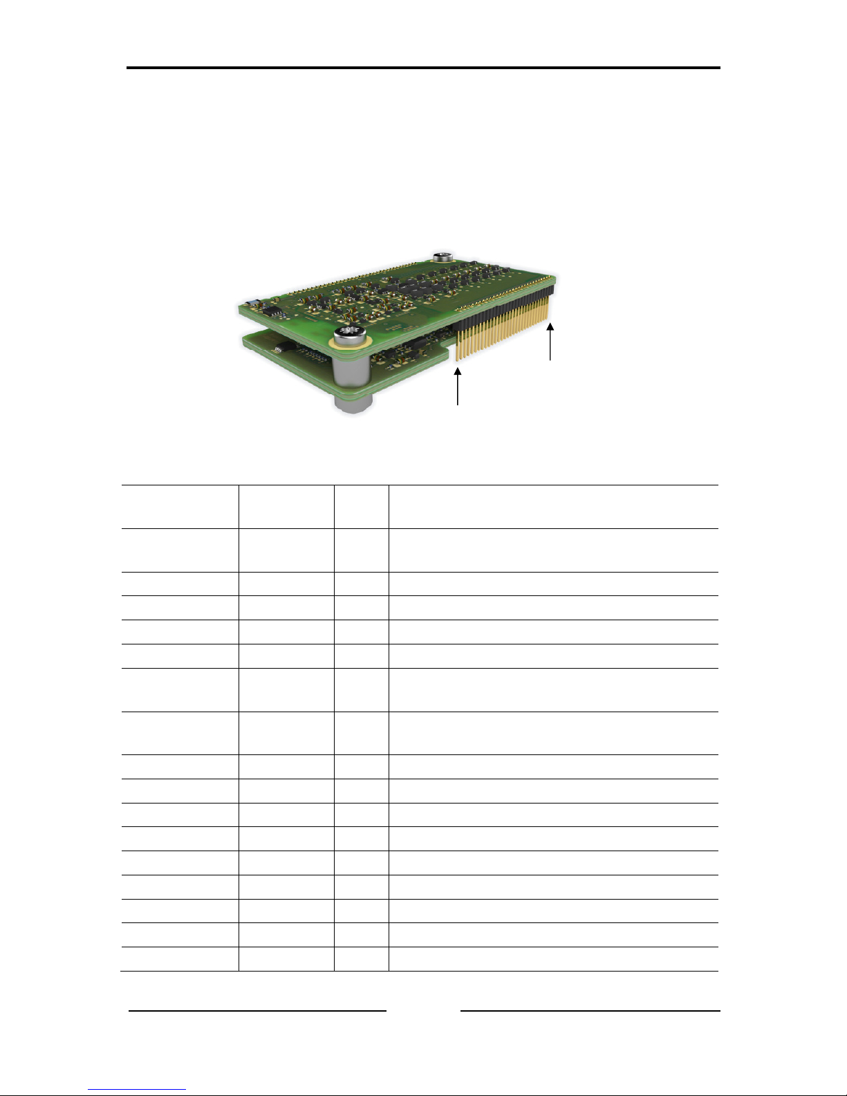
3.3 Pinning
The T100 is designed as an add-on module for easy integration into customer
safety devices. The only electrical connectivity between the customer device
and the T100 is done using a 30-Pin male connector (see Figure 3-1 and the
table below).
Figure 3-1: IXXAT Safe T100 Module
Pin No. Signal
Name
Type Description
1,2
24V PWR 24 V DC (SELV/PELV) power supply from
external source
3,4 VSS PWR Power ground reference
5,6 DO 1 O Digital Output 1
7,8 DO 2 O Digital Output 2
9 VSS PWR Power ground reference
10 TO1 O
Test Output 1. Power supply provided by
T100 to external sensors
11 TO2 O Test Output 2. Power supply provided by
T100 to external sensors
12 N.C. PWR External connection to VSS1
13 DI1 I Digital Input 1
14 N.C. PWR External connection to VSS1
15 DI2 I Digital Input 2
16 N.C. PWR External connection to VSS1
17 DI3 I Digital Input 3
18 N.C. PWR External connection to VSS1
19 DI4 I Digital Input 4
20 N.C. PWR External connection to VSS1
Pin 1
Pin 30

T100 operation
Copyright HMS TC Ravensburg GmbH
27
IXXAT Safe T100 Manual, Version 3.1
21 DI5 I Digital Input 5
22 N.C. PWR External connection to VSS1
23 DI6 I Digital Input 6
24 N.C. PWR External connection to VSS1
25 EXT_0V PWR Communication bus interface ground
26 EXT_3V3 PWR 3.3 V DC power supply from external
source for the communication bus
interface and the reset line.
27 RX I Communication bus interface
28 Tx O Communication bus interface
29 N.C. PWR External connection to EXT_0V
30
____
RST
I
Reset (active low signal)
I: Input
O: Output
PWR: Power
N.C. Not connected
1
: External ground connection necessary to exclude undetected direct
short-circuit between neighboring connector pins
T100 operation
Copyright HMS TC Ravensburg GmbH
28
IXXAT Safe T100 Manual, Version 3.1
3.4 Power Supply
The following list shows the T100 connector pins relevant for the connection of
the external power sources.
Signal Name
Type Pin No. Description
24V PWR 1,2
24 V DC (SELV/PELV) power supply
from external source
VSS PWR 3,4,9 Power ground reference
EXT_3V3 PWR 26 3.3 V DC power supply from external
source for the communication bus and
the reset line.
EXT_0V PWR 25 communication bus interface ground
N.C. PWR
12,14,
16,18,20,22,
24,29
Must be externally connected to power
ground reference VSS
[IDR-3.1] Attention: The unconnected pins (N.C.) of the T100 connector
shall be connected to the SELV/PELV ground VSS.
3.4.1 Voltage Levels and Power Consumption, 24V
The T100 shall be supplied by a 24V DC SELV/PELV1 supply voltage [HR_90].
According to IEC61131-2 the supply voltage shall be 24V DC -20%/+25%
[HR_158]. Reference levels for the external power supply (24V) are given
below 2.
Parameter Unit Min Typ. Max
Power supply (24V) DC
V 19.2 24 30
P
tot
W 1.5 30 60
1
See EN60950-1, §2.2. The voltage must not exceed 60V DC under normal
and single-fault conditions.
A SELV circuit must have protective-separation (reinforced insulation or
protective screening) from all circuits other than SELV/PELV and a simple
separation from other SELV/PELV systems and ground.
A PELV circuit requires protective-separation from all circuits other than
SELV/PELV (i.e., all circuits that might carry higher voltages), but it may have
connections to other PELV systems and ground.
2
EN 61131-2, table 6
T100 operation
Copyright HMS TC Ravensburg GmbH
29
IXXAT Safe T100 Manual, Version 3.1
The IXXAT Safe T100 internal power consumption at 24 V does not exceed
1.5 W. Note that a non-resettable fuse limits the T100 internal current to a
maximum of 2 A. The digital outputs and the test outputs of the T100 are
directly driven from the non-fused 24V SELV/PELV input.
The external power consumption for each of the digital outputs shall not
exceed the following ratings when being connected to external devices:
• I
max_DO
= 500 mA (see section 3.5.3)
• P
max_DO
= 15 W
The test outputs shall not exceed
• I
max_TO
= 100 mA (see section 3.5.2)
[IDR-3.2] Warning: The 24V signal shall be connected to pin 1 and 2 of
the T100 connector.
[IDR-3.3] Danger: The VSS signal (24V ground) shall be connected to pin
3, 4 and 9 of the T100 connector. [HR_342]
[IDR-3.4] Warning: The VSS signal (24V ground) shall be connected to
pin 12, 14, 16, 18, 20, 22, 24 and 29 of the T100 connector to detect
connector errors (short ciruits between neighbor signal pins).
[IDR-3.5], [SAR-3.2] Danger: The T100 shall be supplied by a 24V
SELV/PELV power supply according to EN60950-1 [DR_C_HW_POW,
DR_I_POW] which limits the maximum voltage in case of a failure to 60V.
[PRS_107], [HR_158]
[IDR-3.6], [SAR-3.3] Warning: The maximum constant supply voltage of
30V shall not be exceeded in order to avoid permanent damage of the
T100.
No specific buffer capacitors at the 24V input are necessary to guarantee the
safe operation of the T100. Upon power loss, under voltage or power dips the
T100 enters automatically the fail-safe state.
T100 operation
Copyright HMS TC Ravensburg GmbH
30
IXXAT Safe T100 Manual, Version 3.1
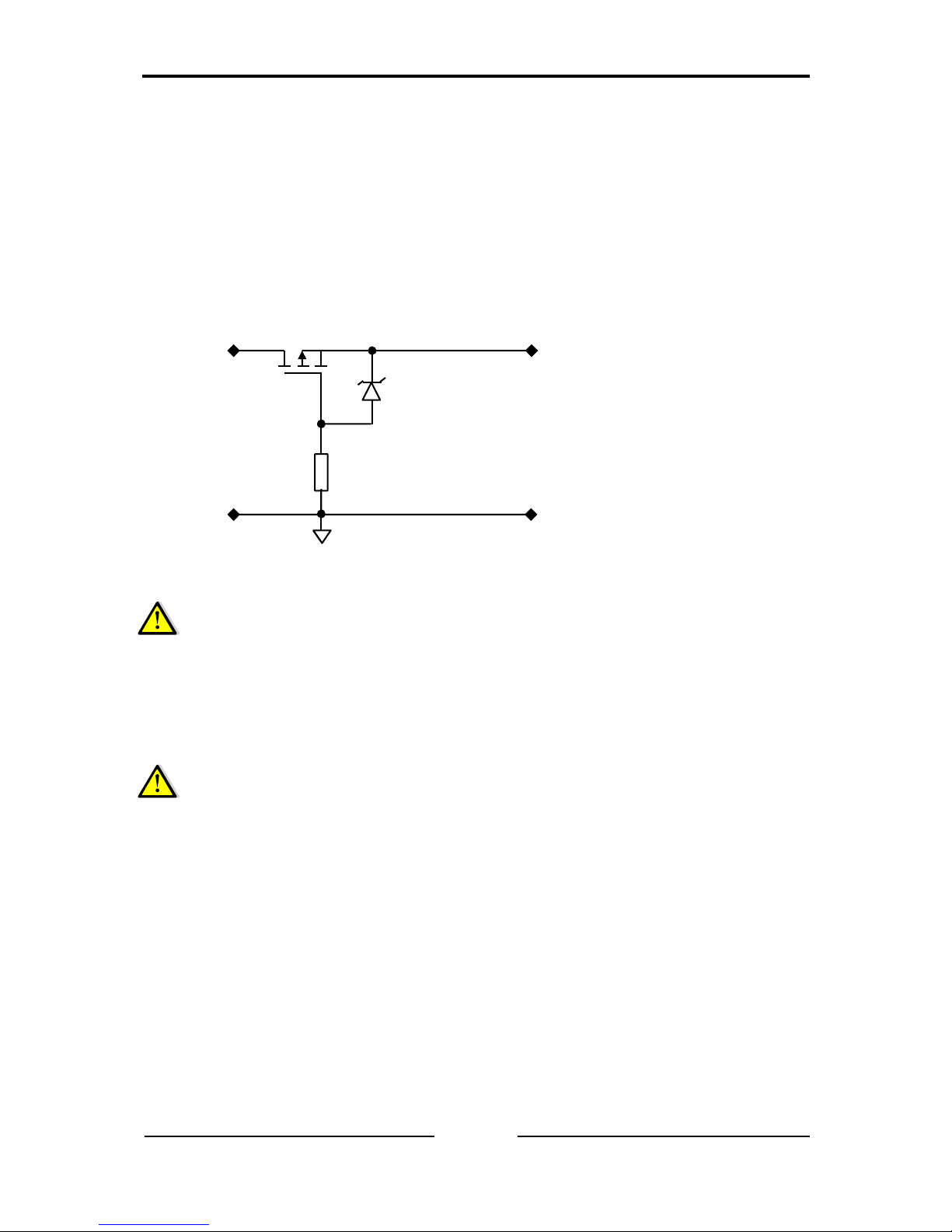
3.4.2 Reverse Battery Protection, 24V
The T100 does not include a reverse battery protection. Therefore, an
external protection circuit as shown in Figure 3-2 shall be implemented on the
customer device. The reverse battery protection circuit itself needs not to be
considered and designed as a safety critical circuit. Nevertheless, it prevents
the T100 to get irreversibly damaged in case of reverse battery connection.
M1
Si4401DY
D1
BZX84C8V2L
R1
47k
>= 0402
Input
SELV/PELV
24V
Vss
Output
SELV/PELV
reverse battery
protected
24V
Vss
Figure 3-2: Reverse battery protection circuit example
[IDR-3.7] Warning: The customer device shall include a reverse battery
protection circuit if the CDev does not generate the 24V DC supply
internally. [SC_425]
[Reverse power connection can be excluded by design when using an
internal power supply as no change to the internal power supply chain is
assumed to be done in the field]
[SAR-3.4] Danger: The proper operation of the reverse battery protection
circuit shall be tested whenever the power supply chain of the T100 is
changed. This test shall be part of the initial safety machine operation
tests where all safety functions shall be tested at least once. Changes to
the power supply during runtime are not allowed without explicit re-testing
of the overall safety function.
 Loading...