

HMS Ixxat iPC-I 320 Hardware Manual
iPC-I 320
Intelligent PC/C AN Interf a c e
HARDWARE MANUAL
ENGLISH

E-Mail: info-ravensburg@hms-networks.de
Support
For problems or support with this product or other HM S products please
Further international support contacts can be found on our webpage
www.ixxat.com
Copyright
Technology Center Ravensburg GmbH. HMS Technology Center
Ravensburg GmbH reserves the right to change technical data without
of the license agreement do apply. All rights are reserved.
Registered trademarks
All trademarks mentioned in this document and where applicable third
of particular registered proprietor. The absence of
identification of a trademark does not automatically mean that it is not
protected by trademark law.
Document number: 4.01.0040.20000
Version: 2.8
HMS Technology Center Ravensburg GmbH
Helmut-Vetter-Straße 2
88213 Ravensburg
Germany
Tel.: +49 751 56146-0
Fax: +49 751 56146-29
Internet: www.hms-networks.de
request support at www.ixxat.com/support.
Duplication (copying , printi ng, m icrof ilm or other form s) and t he elec tro nic
distribution of this document is only allowed with explicit permission of HMS
prior announcement. The general business conditions and the regulations
party registered are absolutely subject to the conditions of each valid label
right and the rights

Content
3
iPC-I 320 Manual, Version 2.8
1 Introduction .................................................................................... 5
1.1 Overview .................................................................................. 5
1.2 Features ................................................................................... 5
1.3 Block Diagram ......................................................................... 6
2 Installation ...................................................................................... 7
2.1 Hardware Installation .............................................................. 7
2.2 Software Installation ............................................................... 7
3 Configuration ................................................................................. 8
3.1 Jumper Settings ...................................................................... 8
3.1.1 Setting the Base Address ...................................................... 11
3.1.2 Setting the PC Interrupt ......................................................... 12
3.1.3 Selection of the EPROM Size ................................................ 13
3.1.4 Disable Toggle ....................................................................... 13
3.1.5 Setting Bus Access Cycles .................................................... 13
3.1.6 Providing Current Supply via CAN Plug ................................. 14
3.1.7 Reset Button and LED ........................................................... 14
3.1.8 Earth Connection for Measuring Purposes ............................ 14
3.1.9 Jumper for Port Pins 1.2 and 1.3 ........................................... 14
3.2 Design of the CAN Plugs ...................................................... 15
3.3 Pin Assignment ..................................................................... 15
3.3.1 Connection between CAN Controllers and Bus Transceivers 16
3.3.2 Serial RS232 Interface ........................................................... 17
4 Architecture .................................................................................. 18
4.1 PC Side Memory Assignment .............................................. 18
4.1.1 DPRAM .................................................................................. 18
4.1.2 Semaphores ........................................................................... 18
4.1.3 Reset of the µC from the PC .................................................. 19
4.1.4 Triggering the Interrupt on the µC through the PC ................ 19
4.2 µC-side Memory Assignment ............................................... 19
4.2.1 Program Memory ................................................................... 20
4.2.2 Data Memory .......................................................................... 20
4.2.3 Loader/Application Mode ....................................................... 20
4.2.4 Harvard-Mode ........................................................................ 21
4.2.5 Von-Neumann Mode .............................................................. 22
4.3 Triggering an Interrupt on the P C ........................................ 23

Content
4
iPC-I 320 Manual, Version 2.8
4.4 CAN Controllers .................................................................... 23
4.5 Serial Interfaces .................................................................... 24
Appendix ............................................................................................. 25
Appendix A ................................................................................... 25
Technical Data .............................................................................. 25
Appendix B ................................................................................... 26
Factory Settings ........................................................................... 26
Appendix C ................................................................................... 27
Supply Sources for Data Sheet s ................................................. 27
EC Declaration of Conformi ty ..................................................... 28

Introduction
5
iPC-I 320 Manual, Version 2.8
1 Introduction
1.1 Overview
With the PC/CAN interface iPC-I 320 you have purchased a high-quality
electronic component which has been de veloped and ma nufactured accor ding
to the latest technological standards.
The aim of this manual is to help you familiarize yourself with your interfac e,
also referred to in the following as iPC-I 320. Please read this manual before
beginning with the installation.
The manual also describes, a mong other things, the hardware architec ture of
the interface, knowledge of which is required in order to create your own
applications on the interface.
If you are using the interface with the IXXAT VCI driver or other IXXAT software,
you can leave out Section 4. For information concerning the development of
own software running on the interf ace, please contact HMS or take a look on
the support area of the HMS homepage (www.ixxat.com
).
1.2 Features
The most important technical features are as follows:
• Design as ISA card (PC plug-in card, half length), PC/104 card or
AT96 / ISA96 card (Euro card format)
• 8-bit memory-mapped access (7 kbytes address space required)
• Base address can be set in the PC via DIP switch (in the range of C000h-
FE00h in 8k steps)
• PC interrupts can be set via jumpers (IRQ 3, 4, 5, 7, 9, 10, 11, 12, 14, 15)
• Microcontroller DALLAS 80C320 with 22.1184 MHz frequency (command
compatible with INTEL 8032)
• One or two CAN circuits via Philips SJA1000 and/or INTEL 82527 CAN
controller with 16 MHz frequency
• 4 kbyte dual-port RAM (DPRAM), 8 semaphore registers
• 32 kbyte EPROM (optional 64 kbyte EPROM)
• up to 63 kbytes code loadable
• up to 2x56 kbytes XDATA RAM operable
• two serial interfaces according to RS232C as an option
• CAN bus transceivers according to ISO/IS 11898 High Speed are on board
(electrically isolated as an option); alternatively, bus couplings can be
made via pin boards and plug-in cards
• optionally one or two CAN protective circuits on board
• downloadable (Intel HEX file format); max. 56 kbytes code
• various memory architectures (Harvard, von-Neumann)
• EMC compatible printed circuit design (4-layer multilayer)
6
iPC-I 320 Manual, Version 2.8
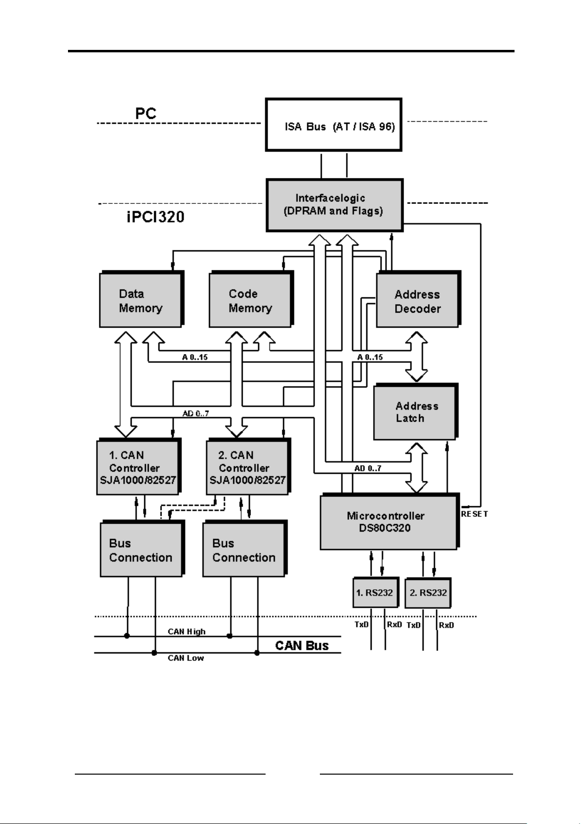
1.3 Block Diagram
Introduction

Installation
7
iPC-I 320 Manual, Version 2.8
2 Installation
2.1 Hardware Installation
For all work on the PC and interface, you must be static ally discharged. The
work must be carried out on an earthed, anti-static work-mat.
Carry out the following work in sequence:
(1) Establish a free memory segment on the PC of at least 8 kbyte in the
range < 1MB (ISA memory range) and a free IRQ. For this, read the
manual of your PC.
(2) Set this memory segment and the IRQ on the interface, as described in
Section 3.1.
(3) Switch the PC off and remove the mains plug.
(4) Open the PC according to the instructions of the PC-manufacturer and
determine a suitable plug-in space.
The interface is designed according to the PC-standard and can be easily
built into the computer. Do not use force when plugging in.
(5) Ensure that the interface is held safely in place in the PC.
(6) If your interface is assembled with 2 isolated CAN-circuits, you must fix
the additional slot plate and plug in the header on the interface (see
Section 3.2).
(7) Close the PC; the hardware installation is now completed.
2.2 Software Installation
To operate the interface, a driver is required.
For the installation of the CAN driver VCI under Win95/98/NT/2000, please read
the VCI installation manual.
Configuration
8
iPC-I 320 Manual, Version 2.8
3 Configuration
3.1 Jumper Settings
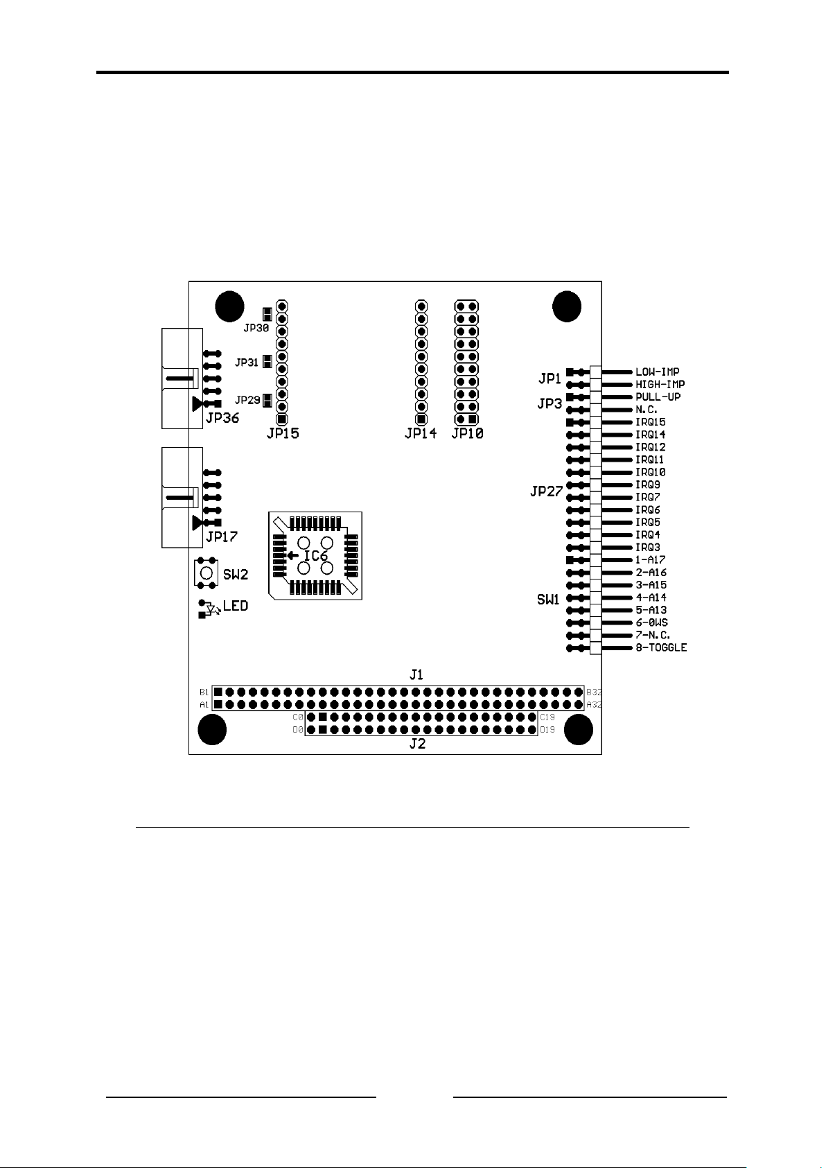
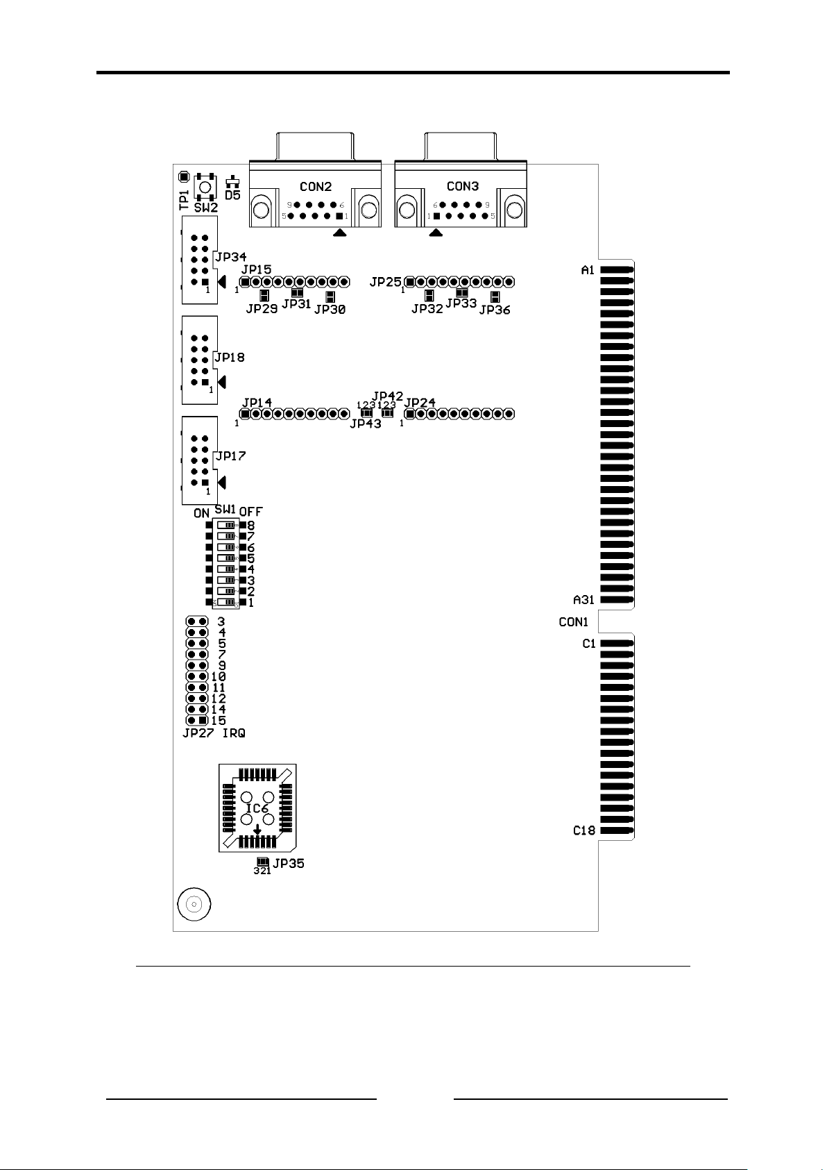
The diagrams Fig. 3-1 (PC/104), Fig. 3-2 (ISA Slot) and Fig. 3-3 (AT/ISA96)
show the positions of the plugs and jumpers on the various interfaces.
Fig. 3-1: iPC-I 320 PC/104 interface for PC/104 computer
Configuration
9
iPC-I 320 Manual, Version 2.8
Fig. 3-2: iPC-I 320 interface for ISA slot bus
 Loading...