

Page 1
INpact Slave PCIe
Industrial Ethernet PCIexpress Interface
USER MANUAL
4.01.0320.20000 1.7 ENGLISH
Page 2

Important User Information
Liability
Every care has been taken in the preparation of this document. Please inform HMS Industrial Networks of any inaccuracies or omissions. The data and illustrations found in this document are not binding. We, HMS Industrial Networks, reserve the right to modify our products in line with our policy of continuous product development. The
information in this document is subject to change without notice and should not be considered as a commitment by
HMS Industrial Networks. HMS Industrial Networks assumes no responsibility for any errors that may appear in this
document.
There are many applications of this product. Those responsible for the use of this device must ensure that all the
necessary steps have been taken to verify that the applications meet all performance and safety requirements including any applicable laws, regulations, codes, and standards.
HMS Industrial Networks will under no circumstances assume liability or responsibility for any problems that may
arise as a result from the use of undocumented features, timing, or functional side effects found outside the documented scope of this product. The effects caused by any direct or indirect use of such aspects of the product are
undefined, and may include e.g. compatibility issues and stability issues.
The examples and illustrations in this document are included solely for illustrative purposes. Because of the many
variables and requirements associated with any particular implementation, HMS Industrial Networks cannot assume responsibility for actual use based on these examples and illustrations.
Intellectual Property Rights
HMS Industrial Networks has intellectual property rights relating to technology embodied in the product described
in this document. These intellectual property rights may include patents and pending patent applications in the USA
and other countries.
INpact Slave PCIe User Manual 4.01.0320.20000 1.7
Page 3

INpact Slave PCIe User Manual 4.01.0320.20000 1.7
Table of Contents
Page
1 User Guide ........................................................................................................................ 3
1.1 Target Audience.............................................................................................................3
1.2 Related Documents .......................................................................................................3
1.3 Document History ..........................................................................................................3
1.4 Trademark Information ...................................................................................................3
1.5 Conventions ..................................................................................................................4
2 Safety Instructions.......................................................................................................... 5
2.1 Information on EMC .......................................................................................................5
2.2 General Safety Notes .....................................................................................................5
2.3 Intended Use .................................................................................................................5
3 Scope of Delivery ............................................................................................................ 5
4 Product Description ....................................................................................................... 6
5 Installation ........................................................................................................................ 6
5.1 Installing the Software ....................................................................................................6
5.2 Installing the Hardware...................................................................................................7
5.3 Connectors....................................................................................................................9
6 Configuration .................................................................................................................10
6.1 Downloading and Updating the Protocol-Specific Firmware.............................................10
6.2 Pre-Configured Protocol-Specific Variants .....................................................................12
7 Operation.........................................................................................................................13
7.1 Overview.....................................................................................................................13
7.2 Boot Up Sequence ....................................................................................................... 14
8 Protocol Variants...........................................................................................................15
8.1 Common Ethernet........................................................................................................15
8.2 EtherCAT ....................................................................................................................17
8.3 EtherNet/IP ................................................................................................................. 19
8.4 Powerlink ....................................................................................................................21
8.5 PROFINET..................................................................................................................23
8.6 Modbus.......................................................................................................................25
9 Technical Specification ...............................................................................................27
9.1 Technical Data ............................................................................................................. 27
9.2 Ordering Information ....................................................................................................27
Page 4

INpact Slave PCIe User Manual 4.01.0320.20000 1.7
Table of Contents
10 Support/Return Hardware ........................................................................................... 28
10.1 Support .......................................................................................................................28
10.2 Return Hardware .........................................................................................................28
11 Disposal........................................................................................................................... 28
A Regulatory Compliance............................................................................................... 29
A.1 EMC Compliance (CE) ................................................................................................. 29
A.2 FCC Compliance Statement .........................................................................................29
B Measurements ...............................................................................................................30
B.1 Ethernet Bus Coupling Unit ........................................................................................... 30
B.2 M12 Bus Coupling Unit .................................................................................................31
Page 5

User Guide 3 (32)
1 User Guide
Please read the manual carefully. Make sure you fully understand the manual before using the
product.
1.1 Target Audience
This manual addresses trained personnel. Trained personnel are all persons who are familiar
with the installation and use. Only ESD trained staff is authorized to install the interface. The
contents of the manual must be made available to any person authorized to use or operate the
product.
1.2 Related Documents
Document Author
Installation Guide VCI Driver HMS
Anybus CompactCom 40 Software Design Guide (see www.anybus.com) HMS
Anybus CompactCom 40 Network Guides HMS
INpact Slave Getting Started HMS
1.3 Document History
Version Date Description
1.0 March 2016 First release
1.1 April 2016 Added INpact CE Slave PCIe Mini
1.2 June 2016 Adjusted FCC Compliance Statement
1.3 October 2016 Integration of measurements and manufacturer address
1.4 March 2017 Added variant BCU ETH M12
1.5 July 2017 Additional information about firmware update, structural changes
1.6 September 2017 Minor corrections firmware update and boot up sequence
1.7 March 2018 Added M.2 version
1.4 Trademark Information
IXXAT®is a registered trademark of HMS Industrial Networks. All other trademarks mentioned
in this document are the property of their respective holders.
INpact Slave PCIe User Manual 4.01.0320.20000 1.7
Page 6
User Guide 4 (32)
1.5 Conventions
Instructions and results are structured as follows:
► instruction 1
► instruction 2
➨ result 1
➨ result 2
Lists are structured as follows:
• item 1
• item 2
Bold typeface indicates interactive parts such as connectors and switches on the hardware, or
menus and buttons in a graphical user interface.
This font is used to indicate program code and other
kinds of data input/output such as configuration scripts.
This is a cross-reference within this document: Conventions, p. 4
This is an external link (URL): www.hms-networks.com
Safety advice is structured as follows:
Cause of the hazard!
Consequences of not taking remediate action.
How to avoid the hazard.
Safety signs and signalwords are used dependent on the level of the hazard.
This is additional information which may facilitate installation and/or operation.
This instruction must be followed to avoid a risk of reduced functionality and/or
damage to the equipment, or to avoid a network security risk.
Caution
This instruction must be followed to avoid a risk of personal injury.
WARNING
This instruction must be followed to avoid a risk of death or serious injury.
INpact Slave PCIe User Manual 4.01.0320.20000 1.7
Page 7

Safety Instructions 5 (32)
2 Safety Instructions
2.1 Information on EMC
Risk of interference to radio and television if used in office or home environment!
Use exclusively included accessories.
Make sure shield of interface is connected with device plug and plug on other side.
Use exclusively shielded cables.
2.2 General Safety Notes
► Protect product from moisture and humidity.
► Protect product from too high or too low temperature (see Technical Data, p. 27).
► Protect product from fire.
► Do not throw, drop or try to bend the product.
► Do not paint the product.
► Do not modify or disassemble the product. Service must be carried out by HMS Industrial
Networks.
► Do not use modified products.
► Store products in dry and dust-free place.
2.3 Intended Use
The interfaces are used to connect computer systems to industrial Ethernet networks. They are
intended for the installation in computer systems with closed housings.
3 Scope of Delivery
Included in the scope of delivery:
• INpact interface (Mini and M.2 version with bus coupling unit and connection cable)
• CD with VCI driver and example application
• Installation Guide VCI Driver
• User Manual INpact Slave PCIe
• Version M12: mounting components
INpact Slave PCIe User Manual 4.01.0320.20000 1.7
Page 8

Product Description 6 (32)
4 Product Description
The IXXAT INpact Slave PCIe for Ethernet based industrial communication is designed to fulfill
the high requirements of real time Ethernet protocols with big data volume and supports the
most used real time industrial Ethernet protocols. The modular approach of the INpact platform
allows the interface to be customized. The IXXAT INpact Slave PCIe is available as Common
Ethernet variant or as pre-configured protocol specific interface. The Common Ethernet variant
can be flashed with various Industrial Ethernet protocols and therefore provides instant connectivity to all major industrial networks with only one interface.
Common feature set:
• one common hardware platform for Industrial Ethernet protocols
• event-based interface method enables easy access to input and output data at any time
• fast data transfer: up to 1500 bytes of process data in each direction with very low latency
• transparent network service channel enables profile integration (Drive, Motion, Semi,
Other)
• standardized hardware and software interface independent of network
• continuous product maintenance by HMS Industrial Networks
• pre-certified for full interoperability and network compliance
• realtime 2-Port-Switch
• 10/100 Mbit, Full-/Half duplex
• Standard, Low Profile, Mini and M.2 version available
• two RJ45 Ethernet ports or two M12 ports
5 Installation
5.1 Installing the Software
For the operation of the interface a driver is needed.
The VCI driver software is constantly improved and expanded! Check if a newer version is available within support area on www.ixxat.com.
Windows
► Install the VCI driver V4 (see VCI Driver Installation Guide).
Linux and Real-Time Operating Systems
► Observe information about supported operating systems and interfaces on www.ixxat.com.
► For information about the installation in Linux see INpact Slave Getting Started.
► When downloading a driver from www.ixxat.com, observe the ReadMe file of the down-
loaded driver package.
INpact Slave PCIe User Manual 4.01.0320.20000 1.7
Page 9
Installation 7 (32)
5.2 Installing the Hardware
Risk of ESD damages caused by improper handling!
Use ESD protective measures to avoid equipment damage.
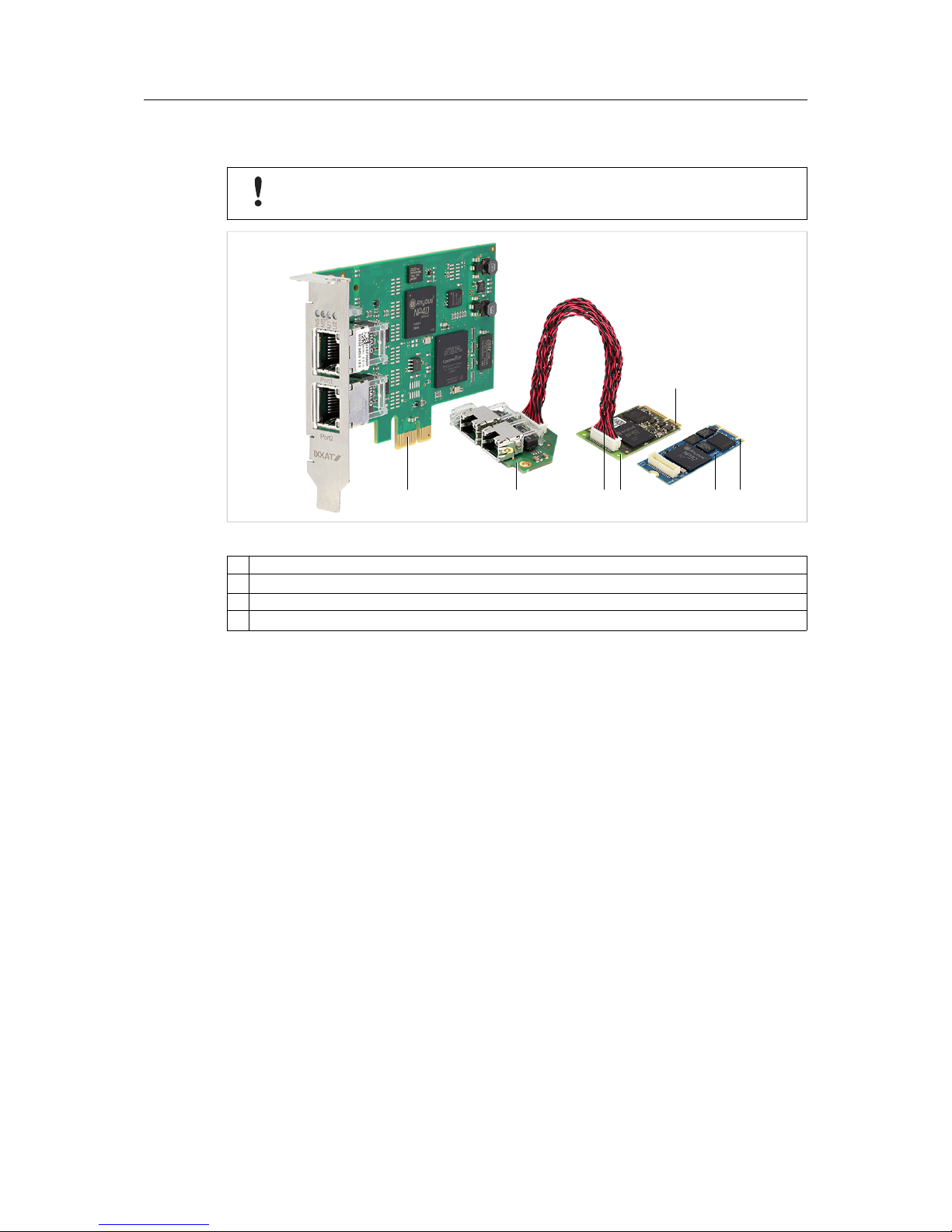
Fig. 1 Low profile and Mini version with Ethernet bus coupling unit
1 Connector
2 Bus coupling unit
3 Connection cable
4 Mini interface (or M.2 interface)
► Make sure that the driver is installed.
► Turn off the computer.
► Pull the power cord.
► Open the computer case according to instructions of the computer manufacturer.
If PCIe Mini or M.2 is used:
► Install the bus coupling unit (2).
► Connect the interface (4) and the bus coupling unit (2) with the connection cable (3).
► If the bus coupling unit M12 is used, connect the LED connector (see Mounting Bus
Coupling Unit M12, p. 8).
► Determine the corresponding slot.
► Plug the connector (1) in the corresponding slot, without using force.
► Make sure that the interface is securely held in the computer.
► If the bus coupling unit M12 is used, fix the bus coupling unit with mounting blocks (see
Mounting Bus Coupling Unit M12, p. 8).
► Close the computer case.
➨ Hardware installation is complete.
1 32 4 1
4
1
INpact Slave PCIe User Manual 4.01.0320.20000 1.7
Page 10
Installation 8 (32)
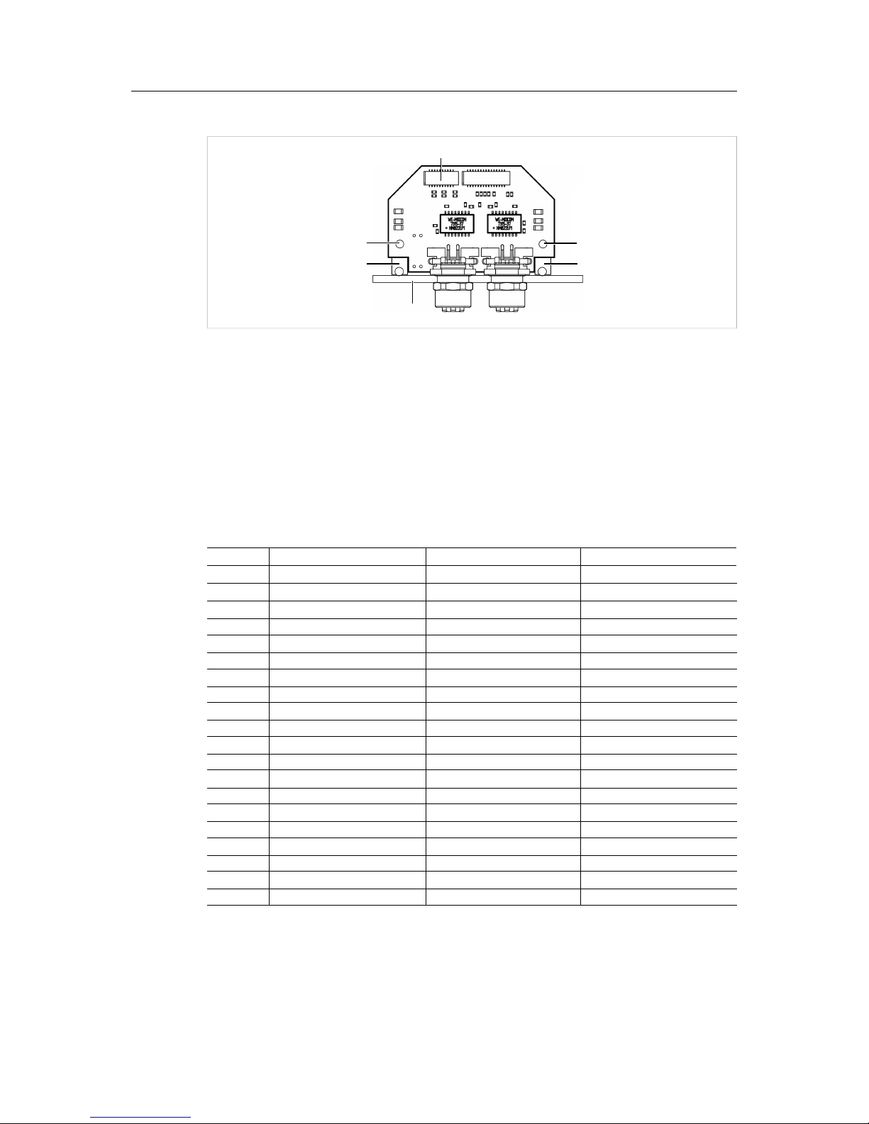
Mounting Bus Coupling Unit M12
Fig. 2 Mounting guides
Tightening moment for M12 thread: 6.25 Nm
Sheet thickness: 2.0 to 3.0 mm
► Screw the mounting blocks (2) onto the bus coupling unit (1).
► Screw the sheet (3) onto the mounting blocks (2).
► Connect the LED connector (4) to the counterpart JST SHDR-20V-S-B.
The function of the LEDs corresponds to the function of the integrated LEDs of the bus coupling
unit Ethernet.
Pin Assignment LED connector
Pin Function Recommended color Signal name
1 LED U1 Green USR1_LED_GR_EXT
2 Power LED Green NetD100_2
3 LED U1 Red USR1_LED_RD_EXT
4 Ground
-
GND
5
LED NS (Network Status) Green NW_LED1A_EXT
6 Ground
-
GND
7
LED NS (Network Status) Red NW_LED1B_EXT
8 Ground
-
GND
9 LED MS (Interface Status) Green NW_LED2A_EXT
10 Ground
-
GND
11 LED MS (Interface Status) Red NW_LED2B_EXT
12 Ground
-
GND
13 Port 1 Link/Activity LED Green NW_LED3A_EXT
14 Ground
-
GND
15 Port 1 Speed Yellow NW_LED3B_EXT
16 Ground
-
GND
17 Port 2 Link/Activity LED Green NW_LED4A_EXT
18 Ground
-
GND
19 Port 2 Speed Yellow NW_LED4B_EXT
20 Ground
-
GND
2 2
3
11
4
INpact Slave PCIe User Manual 4.01.0320.20000 1.7
Page 11
Installation 9 (32)
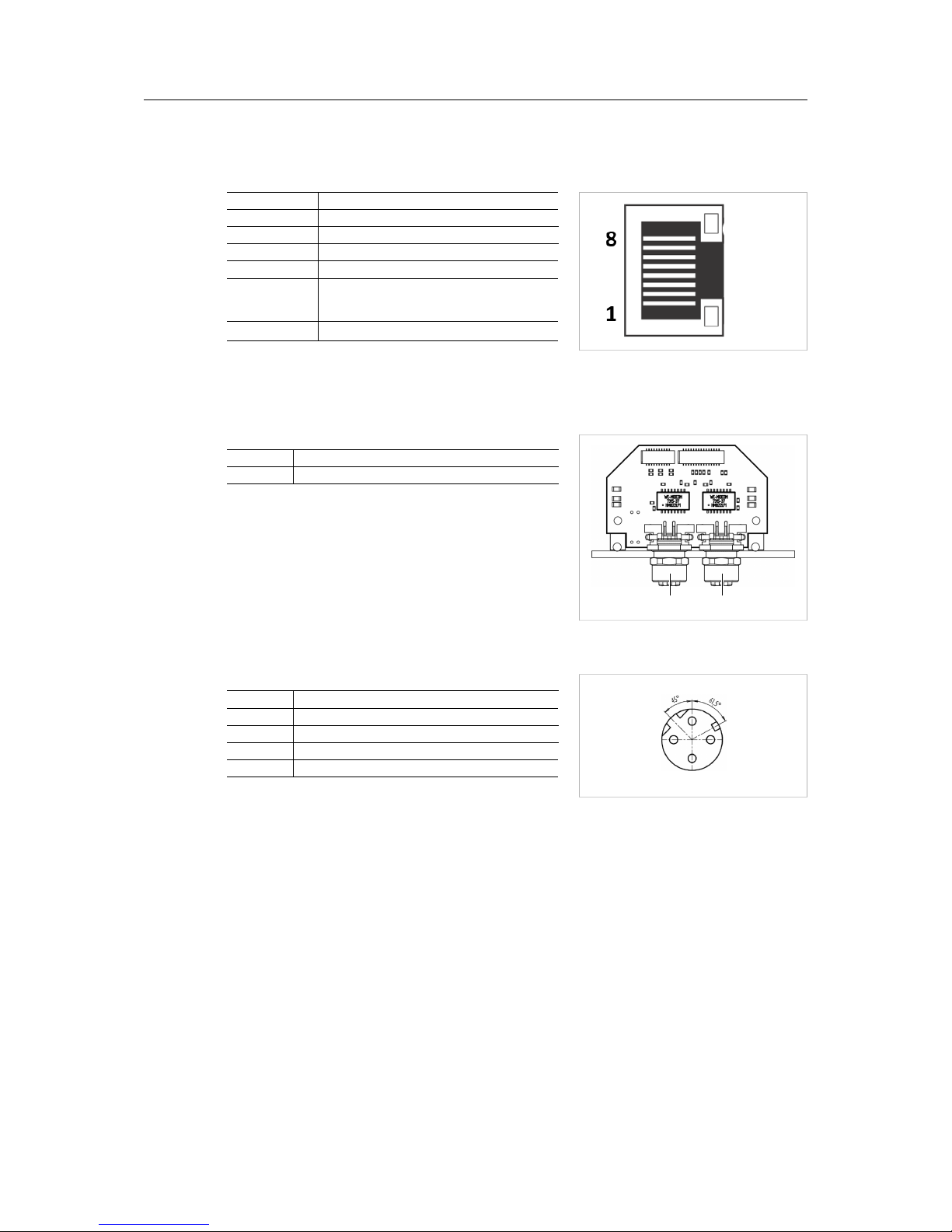
5.3 Connectors
5.3.1 Ethernet Port RJ45
Fig. 3 Pinning RJ45
Pin Function
1 Tx+
2 Tx-
3 Rx+
6 Rx-
4,5,7,8 Normally unused; to ensure signal integ-
rity pins are tied together and terminated
to PE via filter circuit in interface.
Housing Cable shield
5.3.2 M12 Port
Fig. 4 M12 connectors on bus coupling unit M12
1 Port 1
2 Port 2
Fig. 5 Pinning M12 (D-coded, female)
Pin Allocation
Pin Function
1 Tx+
2 Rx+
3 Tx-
4 Rx-
1 2
2
1
3
4
INpact Slave PCIe User Manual 4.01.0320.20000 1.7
Page 12

Configuration 10 (32)
6 Configuration
6.1 Downloading and Updating the Protocol-Specific Firmware
With the INpact Common Ethernet the firmware for the desired protocol must be downloaded to
the interface.
After the configuration of a specific protocol it is possible to switch to other specific protocols. To
restore the Common Ethernet variant is not possible.
6.1.1 Downloading and Updating via Transport Provider
Downloading and updating the firmware via Transport Provider is only possible
with Windows. Via the Transport Provider only one device can be configured at a
time.
VCI driver software is constantly improved and expanded! Check if a newer version is available
within support area on www.ixxat.com.
► Make sure, that the INpact interface is installed in a Windows computer.
► Make sure, that the latest version of the VCI driver V4 is installed.
► Check FPGA version and interface firmware version in the Windows Device Manager in
the tab Hardware Info in the following drop down menus:
CARD Info FPGA ≥ 00.01.03.05
firmware (running) Version ≥ 00.03.07.00
► If the FPGA version or interface firmware version is older, contact IXXATsupport.
► From www.anybus.com download and install the following programs:
– Anybus Transport Provider
– Anybus Firmware Manager II
► In the Anybus Firmware Manager toolbar open Manual Update Wizard.
► Select Anybus CompactCom 40 and click Next
► Select Transport Provider and click Next.
► In window Transport Provider click Create.
► Select INpact and name the path.
➨ Window to select the INpact interface is opened.
► Select the INpact interface to be updated and click OK.
➨ INpact interface is created and available.
► Select the INpact interface to be updated.
► Select the desired protocol and firmware and click Update.
➨ Firmware is downloaded to the interface.
➨ LED MS is flashing red and green.
► When the download is finished click Close.
INpact Slave PCIe User Manual 4.01.0320.20000 1.7
Page 13

Configuration 11 (32)
► With changed protocol, observe the protocol specific LED indications.
► If necessary relabel LED NS and LED MS to conform to specific network certification
requirements.
If the download is interrupted, the download is corrupted! Use the INpact Recovery
Helper to restart.
► If the download is corrupted, run the INpact Recovery Helper in the VCI installation folder.
► Restart the download of the protocol firmware.
6.1.2 Downloading and Updating via Ethernet Connection
Via Ethernet connection several interfaces can be flashed with a protocol at the same time. Via
Ethernet connection downloading and updating of firmware for Linux and other real-time operating systems is possible.
Powerlink can only be downloaded once via Ethernet. To update the Powerlink
firmware use the Transport Provider or update via the application.
Fig. 6 Configure protocol
System conditions
1 Windows computer with HMS firmware manager and ETH protocol files
2 Target systems with installed driver and installed INpact interface with a running application (e.g. example
application described in the IXXAT Software Design Guide INpact Slave Getting Started).
The step-by-step video Firmware Manager for Anybus CompactCom shows a configuration on
Anybus CompactCom hardware. The steps for the INpact interface are the same.
► Download the Anybus Firmware Manager II for Anybus CompactCom from
www.anybus.com to a windows computer (1).
► Connect all interfaces to be updated via Ethernet.
► Make sure, that an application is running on the INpact interfaces to be updated.
► Make sure via IPconfig, that INpact interface and network interface (1) are located in the
same IP address domain (IP and subnet).
INpact Slave PCIe User Manual 4.01.0320.20000 1.7
Page 14

Configuration 12 (32)
► Observe the step-by-step video Firmware Manager for Anybus CompactCom on
www.anybus.com.
► Observe, that the displayed process in the Firmware Manager only shows the state of the
download to the internal memory of the interface.
► When the protocol is downloaded to internal memory, restart the application or the
computer.
► After the restart wait until the protocol is downloaded to the INpact interface. This can take
up to two minutes. Do not interrupt the download.
➨ LED MS is flashing red and green when the download is finished.
► With changed protocol, observe the protocol specific LED indications.
► If necessary, relabel LED NS and LED MS to conform to specific network certification
requirements.
If the download is interrupted, the download is corrupted! Use the INpact Recovery
Helper to restart.
► If the download is corrupted, run the INpact Recovery Helper in the VCI installation folder.
► Observe, that the INpact Recovery Helper can only be run on the Windows computer with
installed VCI driver.
► Restart the download of the protocol firmware.
6.2 Pre-Configured Protocol-Specific Variants
The communication software for the selected protocol is already downloaded to the interface.
To update the firmware of the protocol see Downloading and Updating the Protocol-Specific
Firmware, p. 10. Observe protocol specific LED indications.
INpact Slave PCIe User Manual 4.01.0320.20000 1.7
Page 15

Operation 13 (32)
7 Operation
Risk of damage caused by turning off computer during firmware update!
Do not turn off computer when LED MS is flashing red and green.
7.1 Overview
7.1.1 Standard and Low Profile
Fig. 7 Ethernet Ports and LEDs
No LED Description
1 LED NS (Network Status) Indicates current network status (protocol specific).
2 LED MS (Interface Status) Indicates current module and interface status (protocol specific).
3 LED U1 Indicates state of boot up sequence (see Boot Up Sequence, p. 14).
4 LED U2
–
5
Link/Activity LED Indicates connection and communication status (protocol specific)
6 Port 1
–
7 Port 2
–
Depending on the protocol in use a test sequence of LED NS (1) and LED MS (2) is performed
during the startup.
Port1
Port2
MS
NS
U2
U1
2
1
3
4
5
5
7
6
INpact Slave PCIe User Manual 4.01.0320.20000 1.7
Page 16

Operation 14 (32)
7.1.2 Bus Coupling Unit for Mini Interface and M.2 Interface
The function of the LEDs of bus coupling unit M12 corresponds to the function of the integrated
LEDs of the bus coupling unit Ethernet (see Pin Assignment LED connector, p. 8).
Fig. 8 Ethernet Ports and LEDs on Bus Coupling Unit Ethernet
No LED Description
1 LED NS (Network Status) Indicates current network status (protocol specific).
2 LED MS (Interface Status) Indicates current module and interface status (protocol specific).
3 LED U1 Indicates state of boot up sequence (see Boot Up Sequence, p. 14).
4 Power LED Indicates if power is on or off.
5
Link/Activity LED Indicates connection and communication status (protocol specific)
6 Port 1
–
7 Port 2
–
Depending on the protocol in use a test sequence of LED NS (1) and LED MS (2) is performed
during the startup.
7.2 Boot Up Sequence
In all protocols LED U1 shows the current boot up state and the state of the firmware start.
Boot Up State after Start or Restart of Computer
LED U1 Description
Red flashing Interface in boot manager, information about hardware can be read
with the device manager, ready to start the application
Red Error in boot up sequence, hardware issues. Contact HMS support.
Firmware state after Start of the Application
LED U1 Description
Green flashing Application firmware active
Green High prior task uses CPU time or firmware crashed. Contact HMS
support.
Red Issues with initializing the hardware. Contact HMS support.
2
1
3
4
5
5
7
6
INpact Slave PCIe User Manual 4.01.0320.20000 1.7
Page 17

Protocol Variants 15 (32)
8 Protocol Variants
8.1 Common Ethernet
After the configuration of a specific protocol it is possible to switch to other specific protocols. To
restore the Common Ethernet variant is not possible.
8.1.1 Features
The Common Ethernet interface supports the following functions:
• common hardware platform for Ethernet networks
• web server with customizable content
• FTP server
• e-mail client
• JSON functionality
• Server Side Include (SSI) functionality
• Transparent Socket Interface
8.1.2 Operation (LEDs)
Observe protocol specific LED indications.
Fig. 9 LEDs Common Ethernet
1 LED NS
2 LED MS
3 Link/Activity LED
LED NS
LED state Description
Off Application not started
Green IP address assigned
Green flashing No IP address assigned
Red IP address conflict detected, Error
MS
NS
2
1
3
3
INpact Slave PCIe User Manual 4.01.0320.20000 1.7
Page 18

Protocol Variants 16 (32)
LED MS
LED state Description
Off Not in EXCEPTION or WAIT_PROCESS state
Green In WAIT_PROCESS state
Red EXCEPTION error
Link/Activity LED
LED state Description
Off No link, no activity
Green Link (100 Mbit/s) established
Green flashing Activity (100 Mbit/s)
Yellow Link (10 Mbit/s) established
Yellow flashing Activity (10 Mbit/s)
INpact Slave PCIe User Manual 4.01.0320.20000 1.7
Page 19

Protocol Variants 17 (32)
8.2 EtherCAT
8.2.1 Features
The EtherCATslave interface supports the following functions:
• CANopen over EtherCAT (CoE)
• support for Modular Device Profile
• DS301 compliant
• customizable identity information
• emergency support
• up to 57343 ADIs can be accessed from the network as Manufacturer Specific Objects and
Device Profile Specific Objects (generic mode)
• up to 16383 ADIs can be accessed from the network as Manufacturer Specific Objects and
Device Profile Specific Objects (modular device profile enabled)
• up to 1486 bytes of fast cyclic I/O in each direction
• file access over EtherCAT (FoE)
• support for process data remap from the network
• possible to implement DS402 drive profile, semi device profiles and other device profiles
8.2.2 Operation (LEDs)
Observe renamed LED NS and LED MS.
Fig. 10 LEDs EtherCAT
1 STAT LED (Status)
2 ERR LED (Error)
3 Link/Activity LED
4 EtherCAT (IN)
5
EtherCAT (OUT)
MS
NS
2
1
3
3
5
4
INpact Slave PCIe User Manual 4.01.0320.20000 1.7
Page 20

Protocol Variants 18 (32)
STAT LED
STAT LED (1) reflects status of EtherCATcommunication.
LED state Description Comments
Off Init Interface in INIT state
Green Operational Interface in OPERATIONAL state
Green flashing Pre-operational Interface in PRE-OPERATIONAL state
Green single flash Safe-operational Interface in SAFE-OPERATIONAL state
Flickering Boot Interface in BOOT state
Red If ERR LED 2 also red:
fatal error
Internal error forces interface to passive state
► If STAT LED (1) and ERR LED (2) are red contact HMS Industrial Networks technical
support.
ERR LED
ERR LED 2 indicates EtherCATcommunications errors.
LED state Description Comments
Off Not initialized Interface in SETUP or NW_INIT state
Red blinking Invalid configuration State change received from master not possible due
to invalid register of object settings
Red single flash Unsolicited state change Slave device application has changed the state
autonomously
Red double flash Application watchdog
timeout
Sync manager watchdog timeout
Red Application controller
error
Interface in EXCEPTION state
Flickering Booting error E.g. due to firmware download failure
► If STAT LED (1) and ERR LED (2) are red contact HMS Industrial Networks technical
support.
Link/Activity LED
Link/Aktivity LEDs (3) indicate EtherCAT link status and activity.
LED state Description Comments
Off No link No link, no communication present
Green Link Ethernet link established, no communication present
Green flashing Activity Ethernet link established, communication present
INpact Slave PCIe User Manual 4.01.0320.20000 1.7
Page 21

Protocol Variants 19 (32)
8.3 EtherNet/IP
8.3.1 Features
The EtherNet/IP slave interface supports the following functions:
• beacon based DLR (Device Level Ring) and linear network topology
• web server with customizable content
• FTP server
• e-mail client
• Server Side Include (SSI) functionality
• customizable identity information
• up to 65535 ADIs
• CIP parameter object
• expandable CIP-object implementation
• unconnected CIP routing
• Transparent Socket Interface
• modular device functionality
• QuickConnect
• multiple IO assembly instances can be created
INpact Slave PCIe User Manual 4.01.0320.20000 1.7
Page 22

Protocol Variants 20 (32)
8.3.2 Operation (LEDs)
Fig. 11 LEDs EtherNet/IP
1 LED NS
2 LED MS
3 Link/Activity LED
LED NS
LED NS (1) reflects status of EtherNet/IP communication.
LED state Description
Off No IP address
Green Online, one or more connections established (CIP class 1 or 3)
Green flashing Online, no connections established
Red Duplicate IP address, fatal error
Red flashing One or more connections timed out (CIP class 1 or 3)
LED MS
LED state Description
Off Application not started
Green Controlled by scanner in RUN state
Green flashing Not configured or scanner in IDLE state
Red Major error (EXCEPTION state, fatal error etc.)
Red flashing Recoverable errors:
Interface is configured but stored parameters differ from currently used
parameters.
Link/Activity LED
LED state Description
Off No link
Green Link (100 Mbit/s) established
Green flashing Activity (100 Mbit/s)
Yellow Link (10 Mbit/s) established
Yellow flashing Activity (10 Mbit/s)
MS
NS
2
1
3
3
INpact Slave PCIe User Manual 4.01.0320.20000 1.7
Page 23

Protocol Variants 21 (32)
8.4 Powerlink
Powerlink can only be downloaded once via Ethernet. To update the Powerlink
firmware use Transport Provider or update via application.
8.4.1 Features
The Powerlink slave interface supports the following functions:
• Ethernet Powerlink V2.0 Communication Profile Specification version 1.2.0 (Controlled
Node)
• integrated hub
• 100 Mbit/s, half duplex operation
• ring redundancy
• customizable identity information
• 1 TPDO and 1 RPDO (each can hold 1490 bytes)
• up to 57343 ADIs
• adaptable XDD file included
• segmented SDO transfer
• Poll Response Chaining
• multiplexing
8.4.2 Operation (LEDs)
Observe renamed LED NS and LED MS.
Fig. 12 LEDs Powerlink
1 STATUS LED
2 ERROR LED
3 Link/Activity LED
MS
NS
2
1
3
3
INpact Slave PCIe User Manual 4.01.0320.20000 1.7
Page 24

Protocol Variants 22 (32)
STATUS LED
STATUS LED (1) reflects status of Powerlink communication.
LED state Description
Off Initializing or not active
Green flashing (on 50 ms, off 50 ms) NMT_CS_BASIC_ETHERNET
Basic Ethernet state: no Powerlink traffic
Green single flash NMT_CS_PRE_OPERATIONAL_1
only asynchronous data
Green double flash NMT_CS_PRE_OPERATIONAL_2
asynchronous and synchronous data, no PDO data
(any process data sent is declared not valid and received process data must be ignored)
Green triple flash NMT_CS_READY_TO_OPERATE
ready to operate, asynchronous and synchronous data, no PDO data (any process data sent is declared
not valid and received process data must be ignored)
Green NMT_CS_OPERATIONAL
fully operational, asynchronous and synchronous data, PDO data is sent and received
Green fast flashing (on 200 ms, off 200 ms) NMT_CS_STOPPED
interface stopped (e.g. for controlled shutdown),
asynchronous and synchronous data, no PDO data
(any process data sent is declared not valid and received process data must be ignored)
Red If ERROR LED (2) also red: fatal error
► If STATUS LED (1) and ERROR LED (2) are red contact HMS Industrial Networks technical
support.
ERROR LED
LED state Description
Off No error
Red Recoverable error
If STATUS LED (1) also red: fatal error
► If STATUS LED (1) and ERROR LED (2) are red contact HMS Industrial Networks technical
support.
Link/Activity LED
LED state Description
Off No link
Green Link, no traffic
Green flashing Link and traffic
INpact Slave PCIe User Manual 4.01.0320.20000 1.7
Page 25

Protocol Variants 23 (32)
8.5 PROFINET
8.5.1 Features
The PROFINET slave interface supports the following functions:
• up to 128 submodules in total
• up to 32767 ADIs
• 100 Mbit, full duplex
• generic and PROFINET specific diagnostic support
• complies with PROFINET IO conformance class C
• up to 1440 bytes I/O data in each direction, status bytes included
• SNMP agent
• FTP server
• e-mail client
• Server Side Include (SSI) functionality
• JSON functionality
• customizable identity information
• GSD file template provided by HMS Industrial Networks
• Media Redundancy Protocol (MRP)
• Transparent Socket Interface
INpact Slave PCIe User Manual 4.01.0320.20000 1.7
Page 26

Protocol Variants 24 (32)
8.5.2 Operation (LEDs)
Fig. 13 LEDs PROFINET
1 LED NS
2 LED MS
3 Link/Activity LED
LED NS
LED state Description Comments
Off Offline No connection with IO controller
Green Online (run) Connection with IO controller established, IO control-
ler in RUN state
Green single flash Online (stop) Connection with IO controller established: IO control-
ler in STOP state, IO data bad, IRT synchronisation
not finished
Green flashing Blink Used by engineering tools to identify node on
network
Red single flash Station name error Station name not set
Red double flash IP address error IP address not set
Red triple flash Configuration error Expected information differs from real identification
LED MS
LED state Description Comments
Off Not initialized Interface in setup or NW_INIT state
Green Operational Interface in OPERATIONAL state
Green single flash Diagnostic events Diagnostic events present
Red EXCEPTION error Interface in EXCEPTION state
If LED NS (1) also red:
fatal error
Internal error
Flashing red and green Firmware update Don’t turn off Interface to avoid permanent damage.
► If LED NS (1) and LED MS (2) are red contact HMS Industrial Networks technical support.
Link/Activity LED
LED state Description Comments
Off No link No link, no communication present
Green Link Ethernet link established, no communication present
Green flashing Activity Ethernet link established, communication present
MS
NS
2
1
3
3
INpact Slave PCIe User Manual 4.01.0320.20000 1.7
Page 27

Protocol Variants 25 (32)
8.6 Modbus
8.6.1 Features
The Modbus-TCP slave interface supports the following functions:
• Modbus-TCP server/slave (up to 4 simultaneous connections)
• web server with customizable content
• FTP server
• e-mail client
• JSON functionality
• Server Side Include (SSI) functionality
• customizable identity information
• Transparent Socket Interface
8.6.2 Operation (LEDs)
Fig. 14 LEDs Modbus
1 LED NS
2 LED MS
3 Link/Activity LED
LED NS
LED state Description
Off No IP address or EXCEPTION state
Green At least one Modbus message received
Green flashing Waiting for first Modbus message
Red IP address conflict detected
If LED MS (2) also red: fatal error
Red flashing Connection timeout, no Modbus message received within configured process ac-
tive timeout time
► If LED NS (1) and LED MS (2) are red contact HMS Industrial Networks technical support.
MS
NS
2
1
3
3
INpact Slave PCIe User Manual 4.01.0320.20000 1.7
Page 28

Protocol Variants 26 (32)
LED MS
LED state Description
Off Application not started
Green OPERATIONAL state
Red Error, fatal error
If LED NS (1) also red: fatal error
Red flashing Recoverable error
Flashing red and green Firmware update from file in progress
► If LED NS (1) and LED MS (2) are red contact HMS Industrial Networks technical support.
Link/Activity LED
LED state Description
Off No link, no activity
Green Link (100 Mbit/s) established
Green flashing Activity (100 Mbit/s)
Yellow Link (10 Mbit/s) established
Yellow flashing Activity (10 Mbit/s)
INpact Slave PCIe User Manual 4.01.0320.20000 1.7
Page 29

Technical Specification 27 (32)
9 Technical Specification
9.1 Technical Data
9.1.1 Standard and Low Profile
PC-Interface PCI Express Base Specification, Rev 1.1, single lane port (x1)
Dimensions 64 x 105 mm
Weight approx. 52 g
Operating temperature 0 °C to +70 °C
Storage temperature -40 °C to +85 °C
Power supply Via PCIe socket (3.3/12 V DC)
Current consumption typ. 270 mA/3.3 V DC, 110 mA/12 V DC
Galvanic isolation 1,500 Vrms
Relative humidity 10 % to 95 %, no condensation
9.1.2 Mini Interface
PC-Interface PCI Express Base Specification, Rev 1.1, single lane port (x1)
Form factor F2: Full Mini with bottom-side keep outs
Dimensions 30 x 50.95 x 12 mm (with cable)
Weight Approx. 26 g (interface, cable, bus coupling unit)
Operating temperature -40 °C to 60 °C
Storage temperature -40 °C to +85 °C
Power supply Via PCIe (3.3 V DC)
Current consumption Typ. 600 mA/3.3 V DC
Galvanic isolation 1,500 Vrms
Relative humidity 10 % to 95 %, no condensation
9.1.3 M.2 Interface
PC-Interface PCI Express Base Specification, Rev 1.1, single lane port (x1)
Form factor M.2 2260-D5-B-M
Dimensions 22 x 60 x 12 mm (with cable)
Weight Approx. 25 g (interface, cable, bus coupling unit)
Operating temperature -20 °C to 60 °C
Storage temperature -40 °C to +85 °C
Power supply Via PCIe (3.3 V DC)
Current consumption Typ. 600 mA/3.3 V DC
Galvanic isolation 1,500 Vrms
Relative humidity 10 % to 95 %, no condensation
9.2 Ordering Information
► For ordering numbers and information see www.ixxat.com.
INpact Slave PCIe User Manual 4.01.0320.20000 1.7
Page 30

Support/Return Hardware 28 (32)
10 Support/Return Hardware
Observe the following information in the support area on www.ixxat.com:
• information about products
• FAQ lists
• installation notes
• updated product versions
• updates
10.1 Support
► For problems or support with the product request support at www.ixxat.com/support.
► If required use support phone contacts on www.ixxat.com.
10.2 Return Hardware
► Fill in the form for warranty claims and repair on www.ixxat.com.
► Print out the Product Return Number (PRN resp. RMA).
► Pack product in a physically- and ESD-safe way, use original packaging if possible.
► Enclose PRN number.
► Observe further notes on www.ixxat.com.
► Return hardware.
11 Disposal
► Dispose of product according to national laws and regulations.
► Observe further notes about disposal of products on www.ixxat.com.
INpact Slave PCIe User Manual 4.01.0320.20000 1.7
Page 31

Appendix A: Regulatory Compliance 29 (32)
A Regulatory Compliance
A.1 EMC Compliance (CE)
The product is in compliance with the Electromagnetic Compatibility Directive. More information
and the Declaration of Conformity is found at www.ixxat.com.
A.2 FCC Compliance Statement
This device complies with Part 15 of the FCC Rules. Operation is subject to the following two
conditions:
• This device may not cause harmful interference.
• This device must accept any interference received, including interference that may cause
undesired operation.
Product name IXXAT INpact Slave PCIe
Model CE/ETC/EIP/EIT/PIR/EPL/BCU ETH M12
Responsible party HMS Industrial Networks Inc
Address 35 E. Wacker Dr, Suite 1700
Chicago , IL 60601
Phone +1 312 829 0601
Any changes or modifications not expressly approved by HMS Industrial Networks
could void the user's authority to operate the equipment.
This equipment has been tested and found to comply with the limits for a Class A
digital device, pursuant to part 15 of the FCC Rules. These limits are designed to
provide reasonable protection against harmful interference when the equipment is
operated in a commercial environment. This equipment generates, uses, and can
radiate radio frequency energy and, if not installed and used in accordance with
the instruction manual, may cause harmful interference to radio communications.
Operation of this equipment in a residential area is likely to cause harmful
interference in which case the user will be required to correct the interference at
his own expense.
INpact Slave PCIe User Manual 4.01.0320.20000 1.7
Page 32

Appendix B: Measurements 30 (32)
B Measurements
B.1 Ethernet Bus Coupling Unit
All measurements are in mm.
INpact Slave PCIe User Manual 4.01.0320.20000 1.7
Page 33

Appendix B: Measurements 31 (32)
B.2 M12 Bus Coupling Unit
All measurements are in mm.
INpact Slave PCIe User Manual 4.01.0320.20000 1.7
Page 34

last page
© 2018 HMS Industrial Networks AB
Box 4126
300 04 Halmstad, Sweden
info@hms.se 4.01.0320.20000 1.7.7883 / 2018-03-16
 Loading...