

HMS Ixxat CAN@net NT 420, Ixxat CAN@net NT 200 User Manual
CCAANN@@nneett NNTT
220000 aanndd 442200
USER MANUAL
4.01.0332.20000 1.6 en-US ENGLISH

Important User Information
Liability
Every care has been taken in the preparation of this document. Please inform HMS Industrial Networks of any
inaccuracies or omissions. The data and illustrations found in this document are not binding. We, HMS Industrial
Networks, reserve the right to modify our products in line with our policy of continuous product development. The
information in this document is subject to change without notice and should not be considered as a commitment by
HMS Industrial Networks. HMS Industrial Networks assumes no responsibility for any errors that may appear in this
document.
There are many applications of this product. Those responsible for the use of this device must ensure that all the
necessary steps have been taken to verify that the applications meet all performance and safety requirements
including any applicable laws, regulations, codes, and standards.
HMS Industrial Networks will under no circumstances assume liability or responsibility for any problems that may
arise as a result from the use of undocumented features, timing, or functional side effects found outside the
documented scope of this product. The effects caused by any direct or indirect use of such aspects of the product
are undefined, and may include e.g. compatibility issues and stability issues.
The examples and illustrations in this document are included solely for illustrative purposes. Because of the many
variables and requirements associated with any particular implementation, HMS Industrial Networks cannot assume
responsibility for actual use based on these examples and illustrations.
Intellectual Property Rights
HMS Industrial Networks has intellectual property rights relating to technology embodied in the product described in
this document. These intellectual property rights may include patents and pending patent applications in the USA
and other countries.
CAN@net NT User Manual
4.01.0332.20000 1.6 en-US

Table of Contents
Page
1 User Guide ........................................................................................................................... 3
1.1 Target Audience................... .. ..................................... .. ......................................... .. ........3
1.2 Related Documents ................. ........................................... ....................................... ....... 3
1.3 Document History ..................................... ....................................... ................................3
1.4 Trademark Information............ ....................................... ........................................... ....... 3
1.5 Conventions.......... .. ..................................... .. .................................................................4
2 Safety Instructions .............................................................................................................. 5
2.1 General Safety Instructions ....... .................................................................................. ....... 5
2.2 Intended Use.............................. .. ..................................... .............................................. 5
3 Scope of Delivery ................................................................................................................ 5
4 Product Description ............................................................................................................ 6
4.1 Features ..................... ........................................... ..................................... .. ..................6
4.2 Operational Modes ... .. ..................................... ........................................... ..................... 6
5 Installation........................................................................................................................... 8
5.1 Installing the Software ............................... ....................................... ................................8
5.2 Installing the Hardware ............................................ ..................................... .. ..................8
5.3 Checking and Updating the Firmware ... ..................................... .. ...................................... 10
6 Configuration..................................................................................................................... 12
6.1 Connecting Possibilities..... ....................................... ........................................... ............ 12
6.2 Basic Configuration ..................... .. ..................................... ........................................... . 13
6.3 ASCII Gateway Configuration.................................. .. ........................................... ............. 17
6.4 Bridge Configuration.................... .. ..................................... ........................................... . 18
6.5 VCI Interface Configuration ................................. .. ..................................... .. .................... 19
6.6 Reset to Factory Settings.......... ....................................... ..................................... ........... 20
6.7 Read and erase LOG File.... ........................................... .. ..................................... ............ 20
7 Operation........................................................................................................................... 21
7.1 Ethernet Port .... .. ..................................... ........................................... .. ........................ 21
7.2 Mini USB Port...................... .. ......................................... .. ..................................... .. ...... 21
7.3 Indicators ..... ........................................... ....................................... .............................. 22
CAN@net NT User Manual
4.01.0332.20000 1.6 en-US

8 Default Network Settings ................................................................................................. 24
9 Default TCP/UPD Ports ..................................................................................................... 24
10 Technical Data ................................................................................................................... 24
11 Support/Return Hardware................................................................................................ 25
11.1 Support ................................. ....................................... ................................................ 25
11.2 Return Hardware ..................................................... .. ..................................... .. ............. 25
12 Disposal.............................................................................................................................. 25
A Regulatory Compliance ..................................................................................................... 27
A.1 EMC Compliance (CE) ................................... ..................................... .. ........................... 27
A.2 FCC Compliance Statement ............... .. ..................................... ........................................ 27
A.3 Disposal and recycling............................ ..................................... .. .................................. 28
CAN@net NT User Manual
4.01.0332.20000 1.6 en-US

User Guide 3 (30)
1 User Guide
Please read the manual carefully. Make sure you fully understand the manual before using the
product.
1.1 Target Audience
This manual addresses trained personnel who are familiar with CAN, CAN FD and the applicable
national standards. The contents of the manual must be made available to any person
authorized to use or operate the product.
1.2 Related Documents
Document
Installation Guide VCI Driver
Software Design Guide CAN@net NT 200/420 Generic Protocol for Gateway Mode
User Manual CAN-Gateway Configurator
1.3 Document History
Author
HMS
HMS
HMS
Version
1.0
1.1
1.2
1.3
1.4
1.5 January 2019
1.6
Date
July 2016 First release
October 2016 Adjusted to new Ixxat CAN-Gateway Configurator
July 2017 Changes in configuration tool, added CAN@net NT 420
November 2017
April 2018 Moved parts of the configuration to user manual of CAN-Gateway Configurator
March 2019 Layout changes
Description
Minor corrections
New CAN-Gateway-Configurator version
1.4 Trademark Information
Ixxat®is a registered trademark of HMS Industrial Networks. All other trademarks mentioned in
this document are the property of their respective holders.
CAN@net NT User Manual
4.01.0332.20000 1.6 en-US
User Guide 4 (30)
1.5 Conventions
Instructions and results are structured as follows:
► instruction 1
► instruction 2
→ result 1
→ result 2
Lists are structured as follows:
• item 1
• item 2
Bold typeface indicates interactive parts such as connectors and switches on the hardware, or
menus and buttons in a graphical user interface.
This font is used to indicate program code and other
kinds of data input/output such as configuration scripts.
This is a cross-reference within this document: Conventions, p. 4
This is an external link (URL): www.hms-networks.com
Safety advice is structured as follows:
Cause of the hazard!
Consequences of not taking remediate action.
How to avoid the hazard.
Safety signs and signalwords are used dependent on the level of the hazard.
This is additional information which may facilitate installation and/or operation.
This instruction must be followed to avoid a risk of reduced functionality and/or damage
to the equipment, or to avoid a network security risk.
Caution
This instruction must be followed to avoid a risk of personal injury.
WARNING
This instruction must be followed to avoid a risk of death or serious injury.
CAN@net NT User Manual
4.01.0332.20000 1.6 en-US
Safety Instructions 5 (30)
2 Safety Instructions
Risk of interference to radio and television if used in office or home environment!
Use exclusively included accessories. Use exclusively shielded cables.
Make sure that the shield of the interface is connected with the device plug and the plug
on the other side.
Malfunction caused by extension cable!
According to the USB specification connect the interface directly or via an active USB hub
to the computer. Do not use an extension cable.
2.1 General Safety Instructions
► Protect product from moisture and humidity.
► Protect product from too high or too low temperature (see Technical Data, p. 24).
► Protect product from fire.
► Do not paint the product.
► Do not modify or disassemble the product. Service must be carried out by HMS Industrial
Networks.
► Store products in dry and dust-free place.
2.2 Intended Use
The components are used to connect computer systems to CAN and CAN FD networks and to
connect the networks with each other. They are intended for installation on standard DIN rail.
3 Scope of Delivery
Included in scope of delivery:
• CAN@net NT
• 1 x power connector
• 2 x CAN connector (with CAN@net NT 200)
4 x CAN connector (with CAN@net NT 420)
• User Manual CAN@net NT
• Installation Guide VCI Driver
• Mini USB cable
CAN@net NT User Manual
4.01.0332.20000 1.6 en-US

Product Description 6 (30)
CAN@net N T
(Gateway)
Host System
1
4
3
2
CAN
CAN or CAN-FD
1+2:
3+4:
4 Product Description
The CAN@net NT hardware provides connectivity to Ethernet and CAN networks with various
operational modes. The CAN@net NT 420 additionally is capable of CAN FD. The application
firmware provides functions to access a CAN bus from virtually every Ethernet TCP/IP host. The
CAN@net NT provides message filtering, based on CAN identifiers, for Bridge and Gateway mode
in the direction from CAN system to TCP/IP network. In the Gateway mode the filter can be
configured by ASCII commands. In the Bridge mode the configuration tool is used to configure
the filter. With the VCI driver the CAN@net NT can be used as a PC interface.
4.1 Features
• CAN@net NT 200: 2 x CAN connections, ISO 11898-2 (terminal adapters)
• CAN@net NT 420: 4 x CAN connections, ISO 11898-2 (terminal adapters),
via the CAN-Gateway Configurator two connections can be switched between Classic CAN
and CAN FD
• 1 x RJ45 Ethernet port, 10/100 Mbit/s
• 1 x mini USB 2.0 port, high-speed
• configuration via USB or Ethernet
• With the CAN-Gateway Configurator a configuration can be created, modified, written to
and read from the target device via USB or Ethernet connection.
• platform independent due to ASCII protocol
• Classic CAN/ CAN FD ID filtering
• Classic CAN to CAN FD mapping and CAN FD to Classic CAN mapping (with NT 420)
• cyclic transmission of CAN messages
• MQTT and syslog functionality
• command line program CANGWfile (available for Windows and Linux)
• action rules via if-this-action-then-that-event functionality
4.2 Operational Modes
4.2.1 ASCII Gateway Mode
In the Gateway mode, the CAN@net NT is hooked to the local intranet or internet (firewall
needed). This allows a TCP/IP host within the reach of this intranet or internet to connect to the
CAN@net NT and gain control of the CAN system. The Ethernet TCP/IP host can exchange
commands and CAN messages using the ASCII protocol. The server relays the commands and
messages to the CAN bus and vice versa.
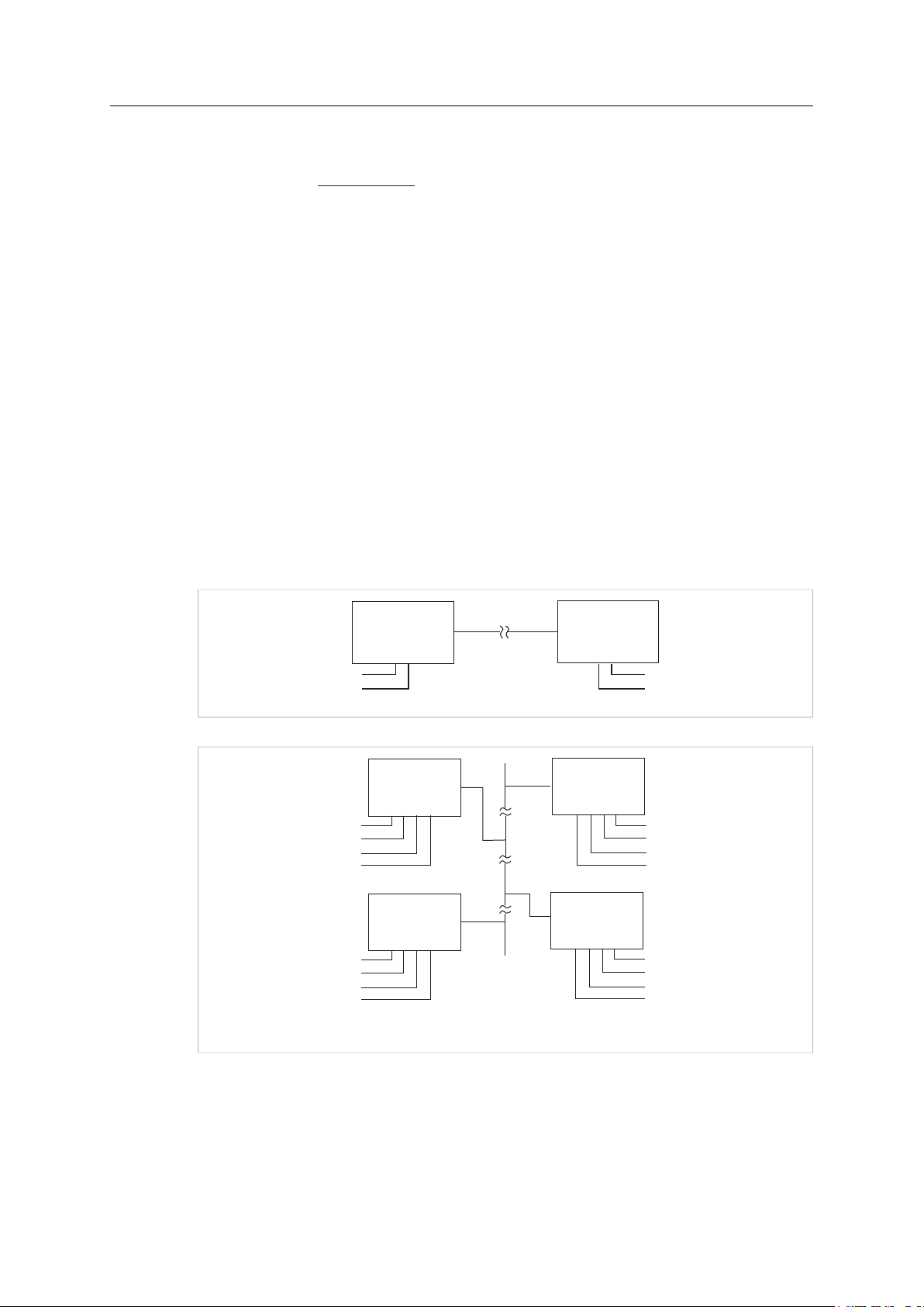
Fig. 1 Gateway mode
CAN@net NT User Manual
4.01.0332.20000 1.6 en-US
Product Description 7 (30)
CAN
CAN@net N T
(Slave)
CAN@net N T
(Master)
1
2
1
2
CAN
CAN
CAN@net N T
(Slave)
CAN@net N T
(Master)
CAN or CAN-FD
1
4
3
2
1+2:
3+4:
1
4
3
2
CAN@net N T
(Slave)
1
4
3
2
CAN@net N T
(Slave)
1
4
3
2
For information about the communication in Gateway mode and commands that are used to
exchange CAN messages see Software Design Guide CAN@net NT 200/420 Generic Protocol for
Gateway Mode on www.ixxat.com.
4.2.2 Bridge Modes
With the CAN@net NT the Bridge mode allows to connect CAN systems over an Ethernet TCP/IP
network, for example the local intranet or the internet (firewall needed). Minimum two devices
are required for a CAN-Ethernet-CAN bridge. One must be configured as master and one as slave.
A single device can be used as Local CAN bridge, which allows to map individual messages from
and to each CAN port of the device.
Possible Bridge Modes with CAN@net NT 200:
• Local CAN Bridge
• CAN-Ethernet-CAN Bridge with 2 devices
Possible Bridge Modes with CAN@net NT 420:
• Local CAN Bridge
• CAN-Ethernet-CAN Bridge with 2 devices
• CAN-Ethernet-CAN Bridge with 3 devices
• CAN-Ethernet-CAN Bridge with 4 devices
Fig. 2 CAN-Ethernet-CAN Bridge with 2 devices (NT 200)
Fig. 3 CAN-Ethernet-CAN Bridge with 4 devices (NT 420)
4.2.3 VCI Interface Mode
With the VCI driver the CAN@net NT can be used as a PC interface. All VCI-based Ixxat tools as
well as customer-specific applications based on the VCI driver can be used. The VCI driver offers
the possibility to communicate with up to 128 CAN@net NT devices via LAN or internet.
CAN@net NT User Manual
4.01.0332.20000 1.6 en-US
Installation 8 (30)
3
1
2
4 5
5 Installation
5.1 Installing the Software
5.1.1 Installing the Driver
For the operation of the CAN-Gateway Configurator and the CAN@net VCI mode a driver is
needed.
The VCI driver is constantly improved and expanded! Check if a newer version is available within the
support area on www.ixxat.com.
► Install the VCI driver (see Installation Guide VCI Driver).
5.1.2 Installing the CAN-Gateway Configurator
The CAN-Gateway Configurator is constantly improved and expanded! Check if a newer version is
available within the support area on www.ixxat.com.
► Download the CAN-Gateway Configurator CANbridge NT & CAN@net NT 200/420 package
from www.ixxat.com.
► Run cangwconfig.exe.
→ Installation wizard starts automatically.
► Follow instructions in installation program.
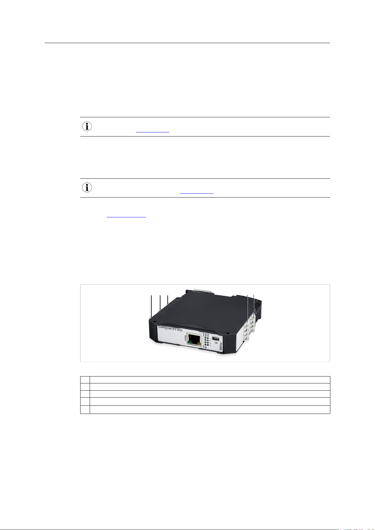
5.2 Installing the Hardware
Fig. 4 Connectors
1 CAN 1
2 CAN 2
3 Power connector
4
CAN 3 (only with CAN@net NT 420)
5
CAN 4 (only with CAN@net NT 420)
► Make sure that the cross-sectional area of the cable is larger than or equal to 0.14 mm2resp.
25 AWG.
► To remove the connector, use screwdriver or similar tool.
► Connect the cables.
CAN@net NT User Manual
► Plug the connector into the housing.
4.01.0332.20000 1.6 en-US
 Loading...