

HMS HMS-EN2MB-R Installation Sheet
HMS-EN2MB-R Linking Device
INSTALLATION SHEET
HMS Industrial Networks AB
Web: www.anybus.com
Tel: +46 35 172900
E-mail: info@hms.se
SP2093, rev 1.02, March 2017. www.anybus.com
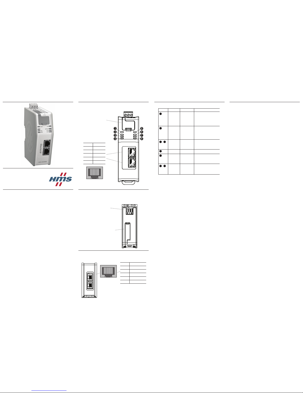
Device Front
Top View
Power:
(+) +24 V DC
(-) GND
(A) FE
SD card slot:
Modbus-TCP Connector:
Pin no Description
1 TX+
2 TX-
3 RX+
6 RX-
4, 5, 7, 8 Termination
18
Bottom View
(Front)
Further informa on and documents about this product can be found at
the product pages on www.anybus.com.
1
2
3
5
6
7
8
4
EtherNet/IP
Connector:
Pin no Description
1 TX+
2 TX-
3 RX+
6 RX-
4, 5, 7, 8 Termination
18
USB port:
Connect a PC to the USB port
for fi rmware upgrades.
LED Indicators
No Name Indication Meaning
Module Status
EtherNet/IP
Off
Alternating red/green
Flashing green
Green
Flashing red
Red
Power off
Boot sequence
Idle
Running
Major or minor recoverable error
Major or minor unrecoverable error
(Exception state or FATAL)
Network Status
EtherNet/IP
Off
Green
Flashing green
Red
Flashing red
No power or no IP address
Online, one or more connections established (CIP Class 1 or 3)
Online, no connections established
Duplicate IP address, FATAL error
One or more connections timed out (CIP
Class 1 or 3)
EtherNet/IP
Ethernet Link 1
and 2
Off
Flashing green
Flashing yellow
No link
Receiving/transmitting Ethernet packets
at 100 Mbit
Receiving/transmitting Ethernet packets
at 10 Mbit
SD Card Green
Red
Accessing SD card
Failure
Modbus-TCP
Status
Off
Green
Flashing green
Flashing red
Red
Power off
Communicating with Modbus-TCP network
Idle
Transaction error or timeout
Fatal error
Modbus-TCP
Ethernet Link 1
and 2
Off
Flashing green
Flashing yellow
No link
Receiving/transmitting Ethernet packets
at 100 Mbit
Receiving/transmitting Ethernet packets
at 10 Mbit
1
2
3 4
5
6
7
8
Installation and Startup Summary
• A ach the linking device to the DIN-rail.
• Connect the device to the EtherNet/IP network.
• Connect the device to the Modbus-TCP network.
• Turn on the device (+24 V DC).
• Assign an IP address to the device using BOOTP-DHCP server.
• Start the Studio 5000 so ware.
• Search in the catalogue for the HMS-EN2MB-R.
• Add the device to the Ethernet network in the I/O confi gura on.
• In the general tab, assign a name and the previously chosen IP
address to the device.
• Confi gure the device using the confi gura on manager and down-
load the confi gura on to the device.
• Set up the EtherNet/IP communica on according to the device
confi gura on.
Technical Details
• Power supply:
24 V DC (-15% to +20%).
• Power consump on:
Maximum power consump on is 300 mA @ 24 V DC.
Typical power consump on: 150 mA @ 24 V DC.
• Surrounding temperature
70 degrees C @ 225 mA @ 24 V DC.
• Func onal Earth (FE):
Internal connec on to FE via DIN-rail or, if the DIN-rail can not be
used, via the power connector.
Note: Make sure the DIN-rail is properly connected to FE.
For maintenance and support, contact the HMS support department.
Contact informa on is available at the support pages on
www.anybus.com.
X1.1
X1.2
X3
X2.2
X2.1
HMS-EN2MB-R Linking Device
INSTALLATION SHEET
Further informa on and documents about this product can be found at
the product pages on www.anybus.com.
Supply voltage: The linking device requires a regulated 24 (20.4-28.8V)
VDC power source.
Field wiring terminal markings (wire type Cu only, 14-30AWG)
“Use 105oC copper (Cu) wire only”
Terminal ghtening torque (5-7 lb-in).
Use in Overvoltage Category I Pollu on Degree 2 Environment.
Install in an enclosure considered representa ve of the intended use.
To comply with ATEX direc ves, the equipment must be installed within
an IP54 enclosure and must be installed with a transient suppressor on
the supply that does not exceed 140% (33.6 V DC) of the nominal rated
supply voltage.
Opera ng temperature/Surrounding temperature:
-25o to +60o degrees C @ 300 mA @ 24 V DC.
NOTE: If the surrounding temperature exceeds +40° C, install the unit
with at least 10 mm of air on each side.
Maximum surface temperature: 135 degrees C.
Pressure: 850 - 1050 millibar.
This product is designed to safely operate in class I, division 2 Hazardous loca on according to ANSI/ISA 12.12.01-2015 and category 3, zone
2 according to EN 60079-0 and EN 60079-15.
SUITABLE FOR USE IN CLASS I, DIVISION 2, GROUPS A, B, C AND D HAZARDOUS LOCATIONS, OR NONHAZARDOUS LOCATIONS ONLY.
Additional Installation and Operating
Instructions
This product is in accordance with the EMC direc ve 2014/30/EU through
conformance with the following standards:
• EN 61000-6-4
Emission standard for industrial environment
EN 55016-2-3, Class A
• EN 61000-6-2
Immunity for industrial environment
EN 61000-4-2
EN 61000-4-3
EN 61000-4-4
EN 61000-4-5
EN 61000-4-6
EMC Compliance (CE)
Warnings
• WARNING - EXPLOSION HAZARD - SUBSTITUTION
OF ANY COMPONENTS MAY IMPAIR SUITABILITY
FOR CLASS I, DIVISION 2.
• WARNING - EXPLOSION HAZARD - WHEN IN HAZARDOUS LOCATIONS, TURN OFF POWER BEFORE
REPLACING OR WIRING MODULES.
• WARNING - EXPLOSION HAZARD - DO NOT DISCONNECT EQUIPMENT WHILE THE CURCUIT IS
LIVE OR UNLESS THE AREA IS KNOWN TO BE
FREE OF IGNITABLE CONCENTRATIONS.
• WARNING - EXPLOSION HAZARD- THE USB CONNECTOR IS NOT FOR USE IN HAZARDOUS LOCATIONS AND FOR TEMPORARY CONNECTION ONLY.
DO NOT USE, CONNECT OR DISCONNECT UNLESS
THE AREA IS KNOWN TO BE NONHAZARDOUS.
CONNECTION OR DISCONNECTION IN AN EXPLOSIVE ATMOSPHERE COULD RESULT IN AN EXPLOSION.
• WARNING - EXPLOSION HAZARD - DO NOT CONNECT OR DISCONNECT THE SD CARD UNLESS
THE AREA IS KNOWN TO BE NONHAZARDOUS.
CONNECTION OR DISCONNECTION IN AN EXPLOSIVE ATMOSPHERE COULD RESULT IN AN EXPLOSION.
• WARNING - INSTALL IN AN ENCLOSURE CONSIDERED REPRESENTATIVE OF THE INTENDED
USE. TO COMPLY WITH ATEX DIRECTIVES, THE
EQUIPMENT MUST BE INSTALLED WITHIN AN IP54
ENCLOSURE AND MUST BE INSTALLED WITH A
TRANSIENT SUPPRESSOR ON THE SUPPLY THAT
DOES NOT EXCEED 140% (33.6 V DC) OF THE
NOMINAL RATED SUPPLY VOLTAGE.
Atex Certifi cation
EX nA IIC T4 Gc
II 3 G
Demko 12 ATEX 1062524X
Y
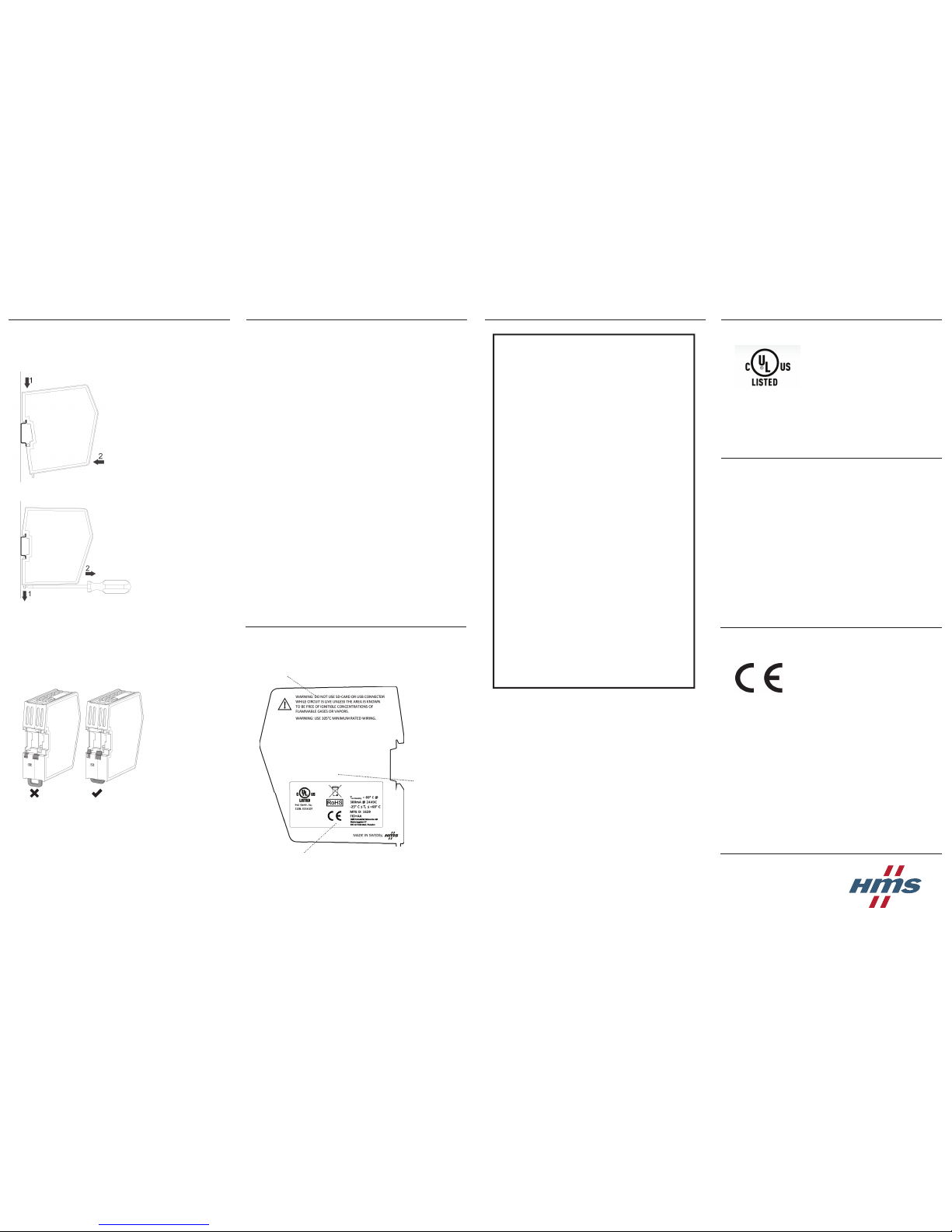
DIN-rail Mounting
Ensure that the DIN-rail fastening
mechanism on the back of the module
is in a fi xed and closed posi on, i. e.
that it is pushed all the way up.
To mount the device, fi rst hook it on
to the DIN-rail (1), then push it against
the DIN-rail to make it snap on (2).
To unmount the device, use a screwdriver to push the DIN-rail fastening
mechanism on the back of the device
down un l it locks in a fi xed and open
posi on (1). Then unhook the device
from the DIN-rail (2).
Note: Do not leave the device with the DIN-rail fastening mechanism in a fi xed
and open posi on. This may cause unneccessary wear on the fastening mecha-
nism, so that it cannot be used effi ciently. Be sure to push the DIN-rail fastening
mechanism back into the fi xed and closed posi on a er unmoun ng the device,
with reference to the picture below.
HMS-EN2MB-R
T
surrounding
= 70oC @ 225mA @24VDC Ityp: 150mA
Label Markings
Surrounding air
temperature and
electrical ra ngs
Cer fi ca on markings
Warnings
HMS Industrial Networks AB
Sta onsgatan 37
302 45 Halmstad
Sweden
UL Certifi cation
Ind. Contr. Eq./Haz.Loc.
22ZB, E214107
67AM, E203225
CL1, DIV 2, GP A, B, C, D
TEMP CODE T4
 Loading...