

HMS FRC-EP170 Hardware Manual
Hardware Manual
FRC-EP170
Automotive Platform
HMS Technology Center Ravensburg GmbH
Helmut-Vetter-Straße 2
88213 Ravensburg
Germany
Tel.: +49 751 56146-0
Fax: +49 751 56146-29
Internet: www.hms-networks.de
E-Mail: info-ravensburg@hms-networks.de
Support
In case of unsolvable problems with this product or other HMS products
please contact HMS in written form:
Fax: +49 751 56146-29
E-Mail: support@ixxat.de
Further international support contacts can be found on our webpage
www.hms-networks.de
Copyright
Duplication (copying, printing, microfilm or other forms) and the electronic
distribution of this document is only allowed with explicit permission of
HMS Technology Center Ravensburg GmbH. HMS Technology Center
Ravensburg GmbH reserves the right to change technical data without
prior announcement. The general business conditions and the regulations
of the license agreement do apply. All rights are reserved.
Registered trademarks
All trademarks mentioned in this document and where applicable third
party registered are absolutely subject to the conditions of each valid
label right and the rights of particular registered proprietor. The absence
of identification of a trademark does not automatically mean that it is not
protected by trademark law.
Document number: 4.01.0142.20000
Version: 1.3
Introduction
Copyright HMS Technology Center
Ravensburg GmbH
3
FRC-EP170 Manual, Version 1.3
1 Introduction .................................................................................... 4
1.1 Overview .................................................................................. 4
1.2 Features of the basic unit ...................................................... 4
2 Connections ................................................................................... 5
2.1 Power plug (6-36 VDC) ........................................................... 5
2.2 Ethernet connector (ETHERNET) .......................................... 7
2.3 USB device connector (USB-B) ............................................. 7
2.4 USB host connector (USB-A) ................................................. 7
2.5 SD card slot ............................................................................. 7
2.6 Displays ................................................................................... 7
2.7 Remote/debug interface (REMOTE) ....................................... 8
2.8 Connector X1 (D-SUB HD15 male) ....................................... 10
2.9 Connector X2 (D-SUB HD15 female) .................................... 10
2.10 Connector X1/2 Signal Details ............................................. 11
2.10.1 FlexRay ................................................................................ 11
2.10.2 CAN Hi/Lo-Speed ................................................................. 11
2.10.3 LIN ........................................................................................ 11
2.10.4 K-LINE .................................................................................. 11
2.10.5 Digital I/O .............................................................................. 11
2.10.6 VBat ...................................................................................... 12
3 Software........................................................................................ 13
3.1 Automotive Configuration Tool............................................ 13
3.2 Installation ............................................................................. 13
3.3 Working with the ACT ........................................................... 13
3.4 Basic data logging configuration ........................................ 13
4 Accessories .................................................................................. 16
5 Appendix ...................................................................................... 17
5.1 Technical data ....................................................................... 17
5.2 Cable for FlexRay-1A ............................................................ 18
5.3 Breakout box for X1/2 ........................................................... 18
5.4 Breakout cable for X1/2 ........................................................ 20
5.5 Support .................................................................................. 21
5.6 Returning hardware .............................................................. 21
5.7 Disposing of old equipment ................................................. 21
Introduction
Copyright HMS Technology Center
Ravensburg GmbH
4
FRC-EP170 Manual, Version 1.3
1 Introduction
1.1 Overview
The FlexRay FRC-EP170 is a powerful platform for the analysis, diagnostics,
and simulation of FlexRay, CAN, LIN, and K-Line networks.
This manual should help you make optimum use of your device. Please read
this manual before starting installation.
1.2 Features of the basic unit
Measurement and analysis platform
Up to two FlexRay interfaces
Up to four high-speed CAN interfaces
Up to one low-speed CAN interfaces
One LIN interface
One K-Line interface
Up to four digital inputs/outputs (5 V TTL Level)
One USB 2.0 device interface
One USB 2.0 host interface
One 10/100 Base-T Ethernet interface
One RS232 interface
Eight LEDs, of which 7 are freely configurable
Real-time clock
SDHC card slot
Up to 32 Gbyte SD card support for logging data
Two internal expansion slots
6-36 VDC power supply range with overvoltage and polarity protection
Standby/hibernate modes
Working temperature range -40 to +80 °C
Remote control (optional)

Connections
Copyright HMS Technology Center
Ravensburg GmbH
5
FRC-EP170 Manual, Version 1.3
Pin
Signal
Description
1
+VDC
Power supply voltage +
2
- (GND)
Power supply ground
3
KL15
Digital input clamp 15
2 Connections
The device has user interfaces (Ethernet, USB, SD Card, LEDs, etc.) on the
front side and field bus interfaces (FlexRay, CAN, LIN, etc.) on the back.
The front of the device is equipped with the following connectors.
Figure 2-1: Front of the FRC-EP170
2.1 Power plug (6-36 VDC)
The unit is supplied with a DC voltage from 6 V to 36 V. The power supply
input is protected against polarity reversal and against overvoltage.
Table 2-1: Pinouts of the 6-36 VDC power plug
Please use the power supply cable provided with the device. This cable is also
available separately as an accessory.

Connections
Copyright HMS Technology Center
Ravensburg GmbH
6
FRC-EP170 Manual, Version 1.3
Pin
Color
Signal
Description
1
white
ws/WT
VDC
+
Power supply +6 to +36 V
with 4 mm red laboratory plug
2
brown
br/BN
Ground
-
Power supply ground
with 4 mm black laboratory plug
3
green
gn/GN
KL15
Digital input clamp15
with 4 mm green laboratory plug
The power supply cable has the following colors on the individual lines.
Table 2-2: Pinouts of the power cable
The type of connector on the FRC-EP 170 is a 3-pin Binder male panel mount
connector, 710 series, 09-0977-00-03.
The type of connector on the cable is a 3-pin Binder female cable connector,
710 series, 99-0976-10x-03.
Clamp 15 (KL15) function
Clamp 15 on the power connector has multiple functions. First, KL15 can be
used as a wake-up from hibernate mode, and KL15 is also used when the
system is turned on or booted to inform the software whether a software
update procedure should be carried out.
A software command can cause the FRC-EP 170 to switch from normal mode
into hibernate mode. If KL15 is activated in hibernate mode, that is, a voltage
of over 6 V is applied, then the device is waked up, the system reboots, and it
is then ready for operation. Before the command for hibernate mode, KL15
must be switched to ground (0 V).
KL15 is equipped with a pull-up resistor to +VDC (~80 kOhms). If KL15 is left
open, the system behaves as though KL15 were still connected to power. This
is the normal case and the system works in normal mode. In this case,
hibernate mode is not possible, since the system would be immediately
wakened again after the command for hibernate mode was issued.
If the system needs to be updated to a new software version, it is possible to
signal this with KL15. If KL15 is connected to ground (0 V) and the device then
turned on, the software enters update mode.
Connections
Copyright HMS Technology Center
Ravensburg GmbH
7
FRC-EP170 Manual, Version 1.3
8
7
6
5
4
3
2
1
2.2 Ethernet connector (ETHERNET)
The Ethernet interface is implemented as a standard Ethernet RJ45.
The Ethernet interface is galvanically isolated from the other interfaces.
2.3 USB device connector (USB-B)
The USB connector is used as a USB device interface to a PC. It is
implemented as a standard USB B type.
The USB interface is not galvanically isolated due to system
constraints, so this interface must be used with corresponding care.
Always provide a grounded connection between your test object and
the FRC-EP170 before connecting the PC to the FRC-EP170 via
USB. Otherwise, a compensation current can flow between the test
object and the PC through the USB connection, which under some
circumstances can damage the PC.
2.4 USB host connector (USB-A)
The USB connector is used to connect USB devices to the FRC-EP170 It is
implemented as a standard USB A type.
2.5 SD card slot
The SD card slot can work with all current SD and SDHC cards. The SD card
slot has a push-push mechanism. To insert the card, push the card until it
stops, at which point you hear and feel a click. The card is then held on its
own. To remove the card, press the card to the stop again.
The holding mechanism releases and the card can be pulled out.
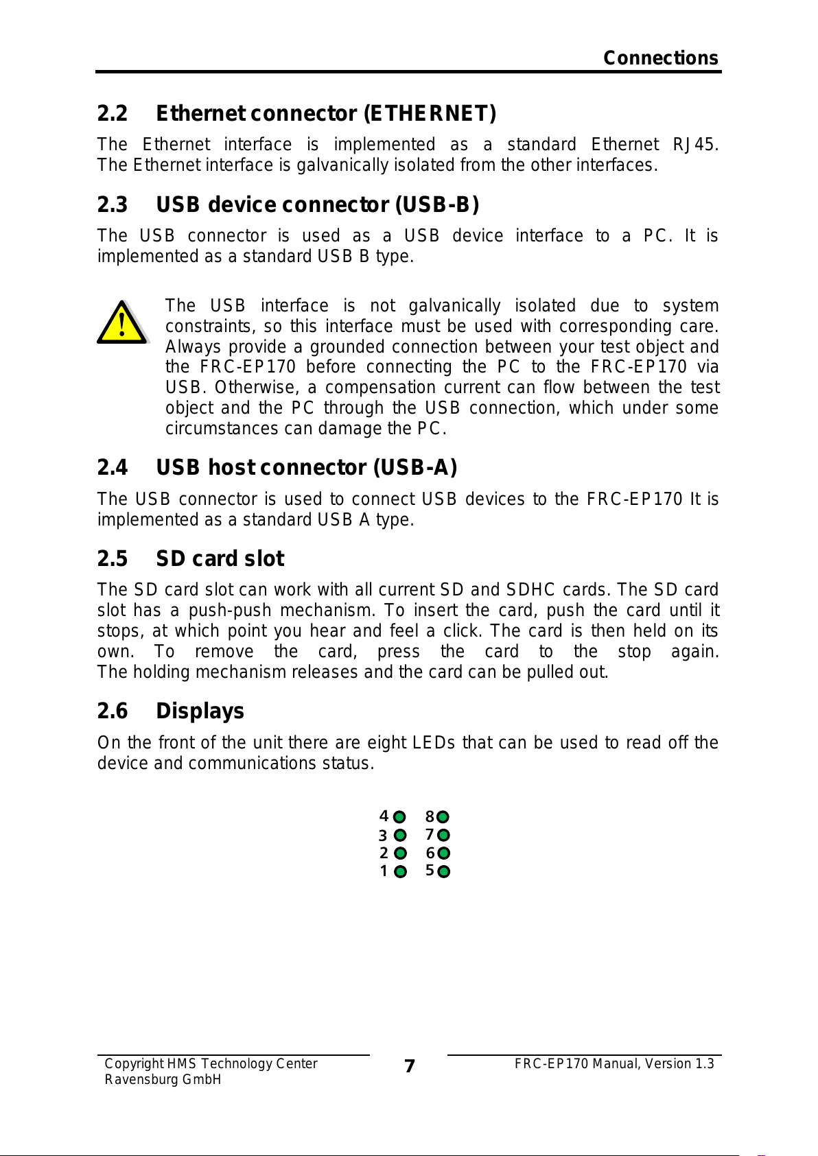
2.6 Displays
On the front of the unit there are eight LEDs that can be used to read off the
device and communications status.
 Loading...