

HMS AnyBus-X J1939 to Modbus Interface User Manual

AnyBus-X
J1939 to Modbus Interface
User Manu al
Doc. id: SCM-7801-026
revision 1.12
HMS Industrial Networks
www.hms-networks.com
Table of Contents i
© 2002 HMS Industrial Networks Document Id: SCM-7801-026
Table of Contents
Preface.........................................................................iii
About This Manual................................................iii
Important User Information...................................iii
Related D o cu mentati o n.................. .............. .......... i v
Document Revision................................................ iv
AnyBus-X Module Description............................... 1-1
Overview.................................................................... 1-1
Theory of Operation................................................... 1-2
J1939 Features .......................................................... 1-3
Modbus Features . ...................................................... 1-3
System Requireme n ts......................... ................. ...... 1-4
Hardware Description................................................. 1-5
Installation................................................................ 2-1
Power and Network Connector .................................. 2-1
Configuration Port Connector..................................... 2-3
Configuration ........................................................... 3-1
AnyBus-X Configuration Tool (BWConfig)................. 3-1
Modbus Network Configuration.................................. 3-6
J1939 Network Configuration. .................................... 3-7
J1939 I/O Configuration ............................................. 3-9
Example Application ............................................... 4-1
Scenario..................................................................... 4-1
Modbus Network Configuration.................................. 4-2
J1939 Network Configuration. .................................... 4-2
J1939 I/O Configuration ............................................. 4-3
Modbus Interface..................................................... 5-1
Network Communication.............. ................. ............. 5-1
Supported Modbus Functions .................................... 5-2
Diagnostic Subfunctions............................................. 5-3
Modbus Addressing ................................................... 5-7
Diagnostic Registers.................................................. 5-9

Table of Contents ii
© 2002 HMS Industrial Networks Document Id: SCM-7801-026
Interaction with I/O Tables ....................................... 5-10
J1939 Interface......................................................... 6-1
Address Management......................... .......... ....... ...... 6-1
Communications Methods.......................................... 6-2
Message Transm ission................ ................. ............. 6-3
Receiving Messages .................................................. 6-5
Transport Protocol for Large Messages..................... 6-6
Bus-Off Reset Option................................................. 6-7
Status a nd D i a g no stics....................... .............. ........ 7-1
AnyBus-X LEDs ......................................................... 7-1
Status Codes.............................................................. 7-3
Specifications.......................................................... 8-1
Environmental Specifications..................................... 8-1
EMC Directive Compliance ........................................ 8-1
Electrical Specifica tions..... ....................... .................. 8-1
Mechanical Specifications.......................................... 8-2
I/O Data Sizes............................................................ 8-3
Modbus Specifications ............................................... 8-3
J1939 Specifications .................................................. 8-3
Connectors................................................................ 9-1
Power and Network 15-Pin D-Subminiature............... 9-1
Configuration 25-Pin D-Subminiature......................... 9-2
Warranty ................................................................ 10-1
Support ................................................................... 11-1
Technical Product Assistance.................................. 11-1

Preface iii
© 2002 HMS Industrial Networks Document Id: SCM-7801-026
Preface
About This Manual
This manual discusses the use of the AnyBus-X J1939 to Modbus Interface. It
describes how to install, configure, and operate the module.
Important User Information
The data and illustrati ons found in this document are not binding. We reserve the
right to modify our products in lin e with our policy of product development. The
information i n this document is subject to change and should not be c onsidered as
a commitment by HMS Industrial Networks. HMS Industrial Networks assumes
no responsibility for errors that may appear in this document
There are many applications of the AnyBus-X module. Those responsible for the
use of this device must satisfy themselve s that all neces sary steps have been take n
to verify an application meets all performance and safety requirements including
any applicable laws, regula tions, codes, and standards.
The illustrations and samples in this guide are intended solely for the purpose of
example. HMS Industrial Networks does not a ssume r esponsibility or lia bility for
actual use based upon the examples shown in this publication.
Modbus is a trademark of Schneider Automat ion.
Microsoft, MS-DOS, and W indows are trademarks of Microsoft Corpor a tion.
Preface iv
© 2002 HMS Industrial Networks Document Id: SCM-7801-026
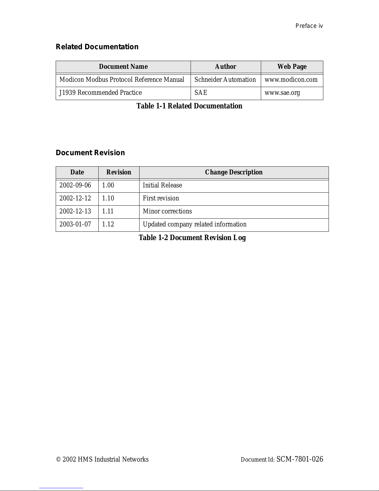
Related Documentation
Document Revision
Document Name Author We b P ag e
Modicon Modbus Protocol Reference Manual Schneider Automation www.modicon.com
J1939 Recommended Practice SAE www.sae.org
Table 1-1 Related Documentation
Date Revision Change Description
2002-09-06 1.00 Initial Release
2002-12-12 1.10 First revision
2002-12-13 1.11 Minor corrections
2003-01-07 1.12 Updated company related information
Table 1-2 Document Revision Log

Chapter 1 AnyBus-X Module Description 1-1
© 2002 HMS Industrial Networks Document Id: SCM-7801-026
AnyBus-X Module Description
Overview
The AnyBus-X J1939 to Modbus Interface (AnyBus- X) allows you to monitor
and control data on a J1939 heavy duty vehicl e networ k using a Modbus RTU
master device. Data from J1939 messages are mapped to I/O table locations, mak-
ing them addressable using standard Modbus read and write commands.
Examples of AnyBus-X applications:
• An interface used on a diesel generator package to access engine parame-
ters from a Programmable Logic Controller (PLC).
• An on-vehicle gateway used to inter face the J1939 vehicle network to an
on board industrial automation based control system.

AnyBus-X Module Description 1-2
© 2002 HMS Industrial Networks Document Id: SCM-7801-026
Theory of Operation
The AnyBus-X provides centraliz e d data storage, the “PassageWayTM”, for data
that is shared between the J1939 and Modbus networks. Data is placed into the
PassageWay by one network interface, allowing the data to be read through the
other network interfa ce.
The AnyBus-X appears as a single device on eit her net work using standard proto-
col mechanisms. No special, or extended, protocol features are required of the
devices on either network to read and write the data flowing through the Passage-
Way; all cross-network activity is transparent to the devices on either network.
Figure 1-1 AnyBus-X PassageWay Operation
Modbus RTU Network
J1939 Network
PassageWay
Input
Table
Output
Table
Receive PGNs
Send PGNs
Read Inputs
Write Outputs

AnyBus-X Module Description 1-3
© 2002 HMS Industrial Networks Document Id: SCM-7801-026
J1939 Features
• Transmission and reception of all types of J1939 messages, including
PDU1, PDU2, broadcast and destinat ion specific.
• Complete network address manag ement including address claim, protec-
tion, and yield on higher priority conflict.
• Network address can be self-configurable over a range of addresses.
• J1939 Transport Protocol for transmission and reception of large mes-
sages (9 - 1785 bytes). Both connection based (RTS/CTS) and broadcast
(BAM) are supported.
• Configurable CAN bus-off reset option will reset the network interface
and attempt to return to online when a CAN bus-off condition is detected.
Modbus Features
• Modbus R TU slave.
• RS-485 half-duplex (2 wire) se ri al interface.
• Configurable baud rates of 4800, 9600, and 19200 bps.
• Configurable for no, odd, or even parity and 1 or 2 stop bits.
• Support of all commonly used Modbus functions f or reading and writing
I/O data and diagnostics.
• Overall module, Modbus, and J1939 status and diagnostics accessible
through Modbus diagnostic functions and addressable registers.

AnyBus-X Module Description 1-4
© 2002 HMS Industrial Networks Document Id: SCM-7801-026
System Require ments
The following hardware and softwa re components are needed to use the AnyBus-
X J1939 to Modbus Interface.
Required Hardware
• AnyBus-X AnyBus-X module.
• J1939 network connection.
• Modbus R TU network connection.
• Modbus R TU master device.
• 24 VDC power connection
• PC to execute AnyBus-X Configurati on Tool (BWConfig) .
• RS-232 null-modem cable to connect PC runni ng BWConfig to the Any-
Bus-X.
Opt iona l Hardware
• DIN rail to mount the AnyBus-X.
Required Software
• AnyBus-X Configuration Tool software (BWConfig) to configure the
AnyBus-X.
• BWConfig requires that the PC be running Micr osoft Windows 95, 98,
NT, or 2000.

AnyBus-X Module Description 1-5
© 2002 HMS Industrial Networks Document Id: SCM-7801-026
Hardware Description
The AnyBus-X J1939 to Modbus Interface has a 15-pin D-Subminiature c onnec-
tor for power and network connections. This connector has pins for module
power , J1939 CAN conne ctions, and Modbus RS-485 connections. See “Ins talla-
tion” Page 2-1 for deta ils on using this connector.
A 25-pin D-Subminiature connector is provided for connection to a PC running
the AnyBus-X Configuration Tool. This is a standard RS-232 DTE connection
and will require a null-modem cable (pins 2 and 3 swapped) to connect the mod-
ule to a PC serial port. See “Installat ion” Page 2-1 for details on using this con -
nector.
The front of the module has a set of 3 LEDs that are used for status indication.
These LEDs provide v isual status for the overall module, the J1939 interface, and
the Modbus interface. See “Status and Diagnostics” Page 7-1 for details on how
the LEDs are used.
The back of the module has a DIN rail mount to allow the module to be mounted
on a DIN rail.
Chapter 2 Installation 2-1
© 2002 HMS Industrial Networks Document Id: SCM-7801-026
Installation
Power and Network Connector
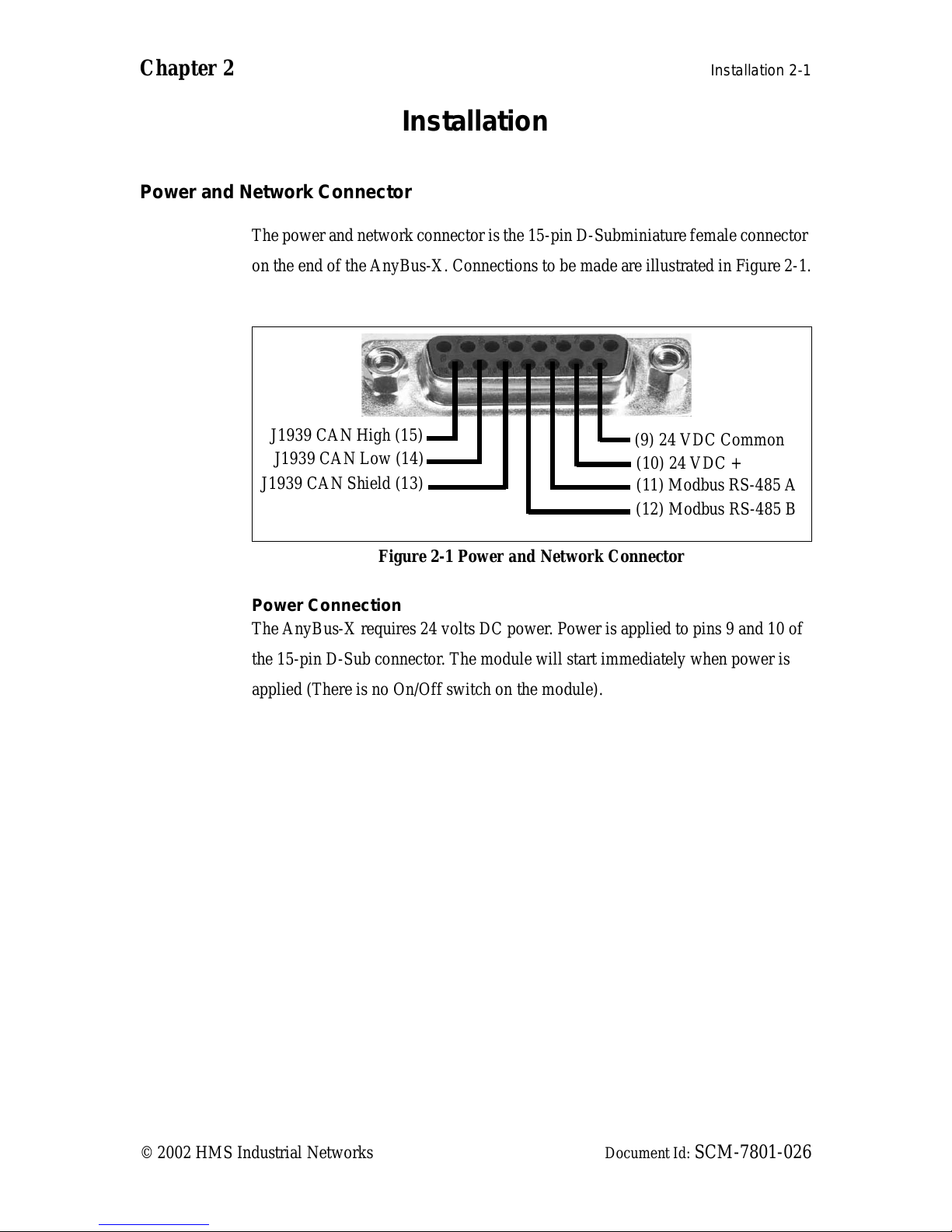
The power and network conne ctor is the 15-pin D-Subm iniature female conne ctor
on the end of the AnyBus- X. C onnections to be made are il lustrated in Figure 2-1 .
Power Connection
The AnyBus-X requires 24 volts DC power. Power is applied to pins 9 and 10 of
the 15-pin D-Sub connector. The module will star t immediately when power is
applied (There is no On/Off switch on the module).
Figure 2-1 Power and Network Connector
(9) 24 VDC Common
(10) 24 VDC +
(11) Modbus RS-485 A
(12) Modbus RS-485 B
J1939 CAN High (15)
J1939 CAN Low (14)
J1939 CAN Shield (13)

Installation 2-2
© 2002 HMS Industrial Networks Document Id: SCM-7801-026
Modbus Network Connection
The RS-485 signals for the Modbus network are connected to pins 11 and 12 of
the 15-pin D-Sub connector. The “A” signal should be connected pin 11, the “B”
to pin 12.
The A and B signal lines should be connected to the A and B connections respec-
tively on all devices on the network. The signal lines should not be swapped on
any device connection.
Note: Some RS-485 equipment uses “+” and “-” descriptors to label the signal
lines. The “-” corresponds to “A”. The “+” corresponds to “B”.
J1939 Network Connection
The J1939 CAN lines are connected to pins 14 and 15, with the CAN shield con-
nected to pin 13 of the 15-pin D-Sub connector . CAN Low is connected to pin 14,
CAN High to pin 15.
The CAN High and Low signal lines should be connected to the CAN High and
Low connections respective ly on all devices on the network. The signal lines
should not be swapped on any device connecti ons.

Installation 2-3
© 2002 HMS Industrial Networks Document Id: SCM-7801-026
Configuration Port Connector
The configuration por t is the 25-pin D-Subminiatur e female connector on the end
of the AnyBus-X. The connector has a standard RS-232 DTE pin configuration.
The connections to be made are shown in Figure 2-2.
The AnyBus-X is connected to a PC for configurat ion using a null-modem cable.
A null-modem cable has pins 2 and 3 swapped so that the PC’s Transm it line is
connected to the AnyBus-X’s Receive line, and the PC’s Receive line is con-
nect e d to the An y Bus-X’s Transm it li ne.
Note: The AnyBus-X does not make use of the modem control signals specified
for a DTE connector. Connecting the module through devices, such as isolation
modules, which assume control of these lines may cause the BWConfig commu-
nications to be unreliable.
Figure 2-2 Configuration Port Connector
(2) Transmit Data
(3) Receive D ataSignal Ground (7)
Chapter 3 Configuration 3-1
© 2002 HMS Industrial Networks Document Id: SCM-7801-026
Configuration
This chapter describes how the AnyBus-X J1939 to Modbus Interface is config-
ured using the AnyBus-X Configuration Tool (BWConfig). Detailed descriptions
of each configurab le paramete r in the AnyBus-X are provide d as well as how th ey
are set in the tool.
The next chapter walks the reader through the configuration of an example appli-
cation to ill ustrate how the configurable parameters are use d in a real-world appli-
cation.
AnyBus- X Conf igu ra ti o n T o ol (B WC onf ig)
The AnyBus-X Configur ation Tool allows you to configure the parameters associ-
ated with the Modbus and J1939 network interfaces as well as to set up the con-
tents and layout of the I/O table.
BWConfig is a Microsoft Windows application that communicates with a Any-
Bus-X over a standard RS-232 serial link using the PC serial port. BWConfig is
compatible with Microsof t Windows 95, 98, NT and 2000.
Installing the Tool
Install BWConfig from the CD by running Setup.exe which is found in the CD's
root directory.
If you have downloaded BWConfig from the web site, unzip the downloaded file
into a temporary director y and run Setup.exe which is found in the temporary
directory.

Configuration 3-2
© 2002 HMS Industrial Networks Document Id: SCM-7801-026
Connecting to the AnyBus-X Module
Connect the PC running BWConfig to the AnyBus-X module using a standard
Null-Modem (pins 2 and 3 swapped) serial cab le betwe en the PC serial port and
the 25-pin D-S ub connect or on t he modul e. It d oes not matte r whic h PC seria l port
you use, BWCo n fig wil l scan eac h avai l abl e p ort and de tect the con n ecti o n auto -
matically.
St arting the Tool
Launch BWConfig from the AnyBus-X Configu ration folder in the Windows Start
Menu.
When BWConfig is started, it will attempt to locate a AnyBus-X module on one
of the PC serial ports. If a module is found, the status area of the tool will be
updated to show the module type and status of the module that was located.
If a module is not c onnected to the PC, or is powered off, when t he tool is started,
the status area will indicate that no module was detected. Make sure that the mod-
ule is powered and the connection is made, then press the Refresh button on the
BWConfig tool ba r; this will cause the tool to rescan the se rial ports for a module.
Configuration 3-3
© 2002 HMS Industrial Networks Document Id: SCM-7801-026
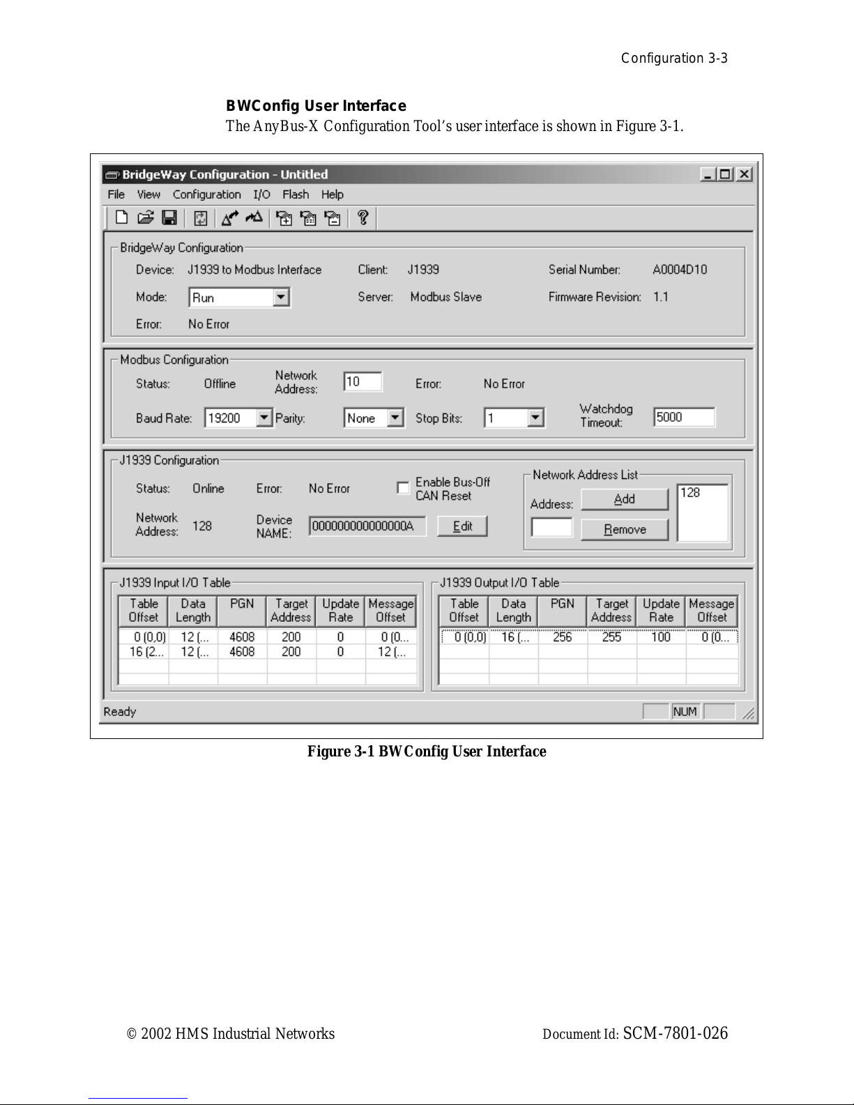
BWConfig User Interface
The AnyBus-X Configuration Tool’s user inte rface is shown in Figure 3-1.
Figure 3-1 BWC onfig User Inte rface
Configuration 3-4
© 2002 HMS Industrial Networks Document Id: SCM-7801-026
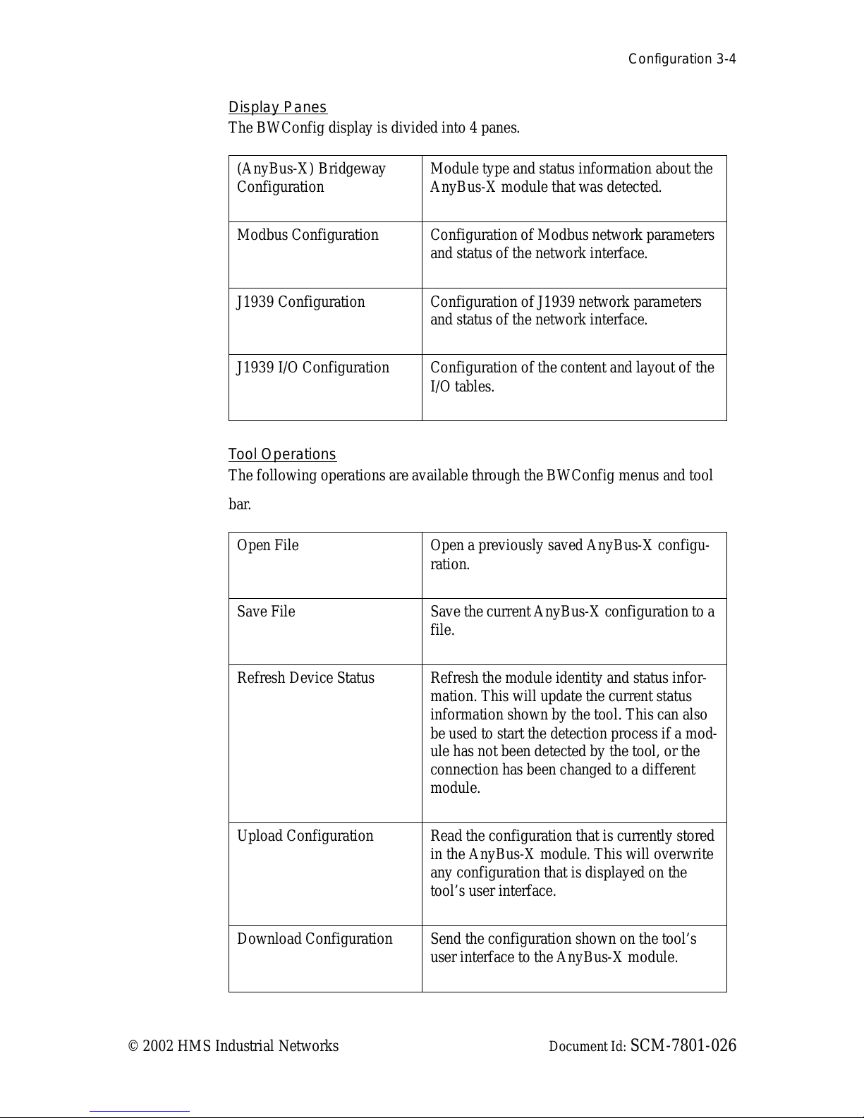
Display Panes
The BWConfig display is divided into 4 panes.
Tool Operations
The following operations a re available through the BWConfig menus and tool
bar.
(AnyBus-X) Bridgeway
Configuration
Module type and status information about the
AnyBus-X module that was detected .
Modbus Configuration Configuration of Modbus network parameters
and status of the network inter face.
J1939 Configuration Configuration of J1939 network parameters
and status of the network inter face.
J1939 I/O Configuration Configuration of the content and layout of the
I/O tables.
Open File Open a previously saved AnyBus-X configu-
ration.
Save File Save the cur rent AnyBus-X configur ation to a
file.
Refresh Device Status Refresh the module identity and status infor-
mation. This will update the current status
information shown by the tool. This can also
be used to start the detect ion process if a mod-
ule has not been detected by the tool, or the
connection has been changed to a different
module.
Upload Configuration Read the configuration that is cur rently stored
in the AnyBus-X module. This will overwrite
any configuration tha t is displayed on the
tool’s user interface.
Download Configuration Send the configuration shown on the tool’s
user interface to the AnyBus-X module.

Configuration 3-5
© 2002 HMS Industrial Networks Document Id: SCM-7801-026
Add I/O Point Add a new input or output data point to the
J1939 I/O configuration.
Edit I/O Point Change the parameters associated with the
selected input or output da ta point in the
J1939 I/O configuration.
Remove I/O Point Delete the selected input or output data point
from the J1939 I/O configuration.
Flash Update Perform a field upgrade of the AnyBus-X
module’s firmware.
Note: Care should be taken when upgrading
firmware, an incomplete update could cause
irreparable harm to the module.
 Loading...