

HMS Anybus X-gateway Ethernet to J1939 Gateway User Manual
HALMSTAD • CHICAGO • KARLSRUHE • TOKYO • BEIJING • MILANO • MULHOUSE • COVENTRY • PUNE • COPENHAGEN
HMS Industrial Networks
Mailing address: Box 4126, 300 04 Halmstad, Sweden
Visiting address: Stationsgatan 37, Halmstad, Sweden
Connecting Devices
TM
E-mail: info@hms-networks.com
www.hms-networks.com
Anybus X-gateway
Ethernet to J1939 Gateway
User Manual
Part No. AB7665
For Firmware Revision 2.07.01 and Later
Manual Revision 1.20
Doc: HMSI-168-27
Table of Contents i
© 2014 HMS Industrial Networks AB Doc: HMSI-168-27
Table of Contents
Preface......................................................................... iv
Important User Information ................................... iv
Related Documentation........................................... v
Support.................................................................... v
................................................................................ v
Anybus X-gateway Module Description ................ 1-1
Overview .................................................................... 1-1
Theory of Operation ................................................... 1-2
J1939 Features .......................................................... 1-3
Ethernet Features ...................................................... 1-3
IT-Features................................................................. 1-4
System Requirements ................................................ 1-5
Hardware Description................................................. 1-6
Installation................................................................ 2-1
Installation and Operation Requirements ................... 2-1
Power and Network Connections ............................... 2-2
Connecting Power...................................................... 2-3
Connecting J1939 ...................................................... 2-4
Connecting to Ethernet .............................................. 2-5
Configuration Port Connector..................................... 2-5
Configuration ........................................................... 3-1
Anybus X-gateway Configuration Tool (BWConfig) ... 3-1
Ethernet Network Configuration ................................. 3-6
J1939 Network Configuration................................... 3-15
J1939 I/O Configuration ........................................... 3-18
Example Application ............................................... 4-1
Scenario #1 - EtherNet/IP .......................................... 4-1
Ethernet Network Configuration ................................. 4-2
J1939 Network Configuration..................................... 4-2
J1939 I/O Configuration ............................................. 4-3
Scenario #2 - Modbus/TCP ........................................ 4-6
Table of Contents ii
© 2014 HMS Industrial Networks AB Doc: HMSI-168-27
Ethernet Network Configuration ................................. 4-7
J1939 Network Configuration..................................... 4-7
J1939 I/O Configuration ............................................. 4-8
EtherNet/IP Interface .............................................. 5-1
Product Features........................................................ 5-1
CIP Objects ................................................................ 5-1
CIP Messaging ........................................................... 5-2
I/O Messaging ............................................................ 5-3
Assembly Objects and Connections........................... 5-4
I/O Data Summary ..................................................... 5-9
Using ControlLogix with the Gateway ...................... 5-11
Modbus/TCP Interface............................................ 6-1
Supported Commands ............................................... 6-1
Supported Exception Codes ...................................... 6-2
Modbus/TCP Addressing ........................................... 6-3
I/O Data Content ........................................................ 6-5
I/O Data Summary ................................................... 6-10
I/O Data Format ....................................................... 6-12
J1939 Interface......................................................... 7-1
Address Management ................................................ 7-1
Communications Methods.......................................... 7-2
Message Transmission .............................................. 7-3
Receiving Messages .................................................. 7-6
Transport Protocol for Large Messages ..................... 7-8
J1939 Diagnostic Messages ...................................... 7-9
Bus-Off Reset Option ............................................... 7-13
Offline Detection....................................................... 7-14
J1939 Baud Rate ..................................................... 7-17
File System................................................................ 8-1
File System Conventions............................................ 8-1
Security ...................................................................... 8-2
Structure..................................................................... 8-4
Default Files ............................................................... 8-5
Virtual File System ..................................................... 8-6

Table of Contents iii
© 2014 HMS Industrial Networks AB Doc: HMSI-168-27
System Files............................................................... 8-6
Configuration Files ..................................................... 8-7
Password Files......................................................... 8-11
Other Files................................................................ 8-13
Anybus X-gateway Web Page Files ......................... 8-17
IT Functionality ....................................................... 9-1
Default User Accounts ............................................... 9-1
The FTP Server.......................................................... 9-2
The Telnet Server ...................................................... 9-2
HTTP Server .............................................................. 9-8
SSI Functionality ........................................................ 9-9
Email Client .............................................................. 9-25
Displaying I/O Data on a Web Page......................... 9-26
Status and Diagnostics........................................... 10-1
Anybus X-gateway LEDs ......................................... 10-1
J1939 Status Codes................................................. 10-4
Diagnostic Web Pages............................................. 10-5
Status Assembly ...................................................... 10-5
Specifications.......................................................... 11-1
Environmental Specifications ................................... 11-1
EMC Directive Compliance ...................................... 11-1
Electrical Specifications............................................ 11-1
Mechanical Specifications ........................................ 11-2
I/O Data Sizes .......................................................... 11-3
J1939 Specifications ................................................ 11-3
Connectors.............................................................. 12-1
Power ....................................................................... 12-1
J1939 ....................................................................... 12-2
Ethernet RJ45 .......................................................... 12-3
Configuration RS-232 9 Pin D-Subminiature............ 12-4

Preface iv
© 2014 HMS Industrial Networks AB Doc: HMSI-168-27
Preface
Important User Information
The data and illustrations found in this document are not binding. We reserve the
right to modify our products in line with our policy of product development. The
information in this document is subject to change and should not be considered as
a commitment by HMS Industrial Networks. HMS Industrial Networks assumes
no responsibility for errors that may appear in this document
There are many applications of the Anybus X-gateway module. Those responsible
for the use of this device must satisfy themselves that all necessary steps have
been taken to verify an application meets all performance and safety requirements
including any applicable laws, regulations, codes, and standards.
The illustrations and samples in this guide are intended solely for the purpose of
example. HMS Industrial Networks does not assume responsibility or liability for
actual use based upon the examples shown in this publication.
FAIL-SAFE OR CRITICAL OPERATIONS
This product is not designed, intended, authorized, or warranted
to be suitable for use or resale as control equipment in, or for
other applications related to, hazardous or potentially-hazardous
environments or applications requiring high-availability or fail-
safe performance, such as in the operation of nuclear facilities,
aircraft navigation or communications systems, air traffic con-
trol, life support, public works, weapons systems, or any other
application in which the failure of a product could lead to prop-
erty damage, death, personal injury, or environmental damage.
Preface v
© 2014 HMS Industrial Networks AB Doc: HMSI-168-27
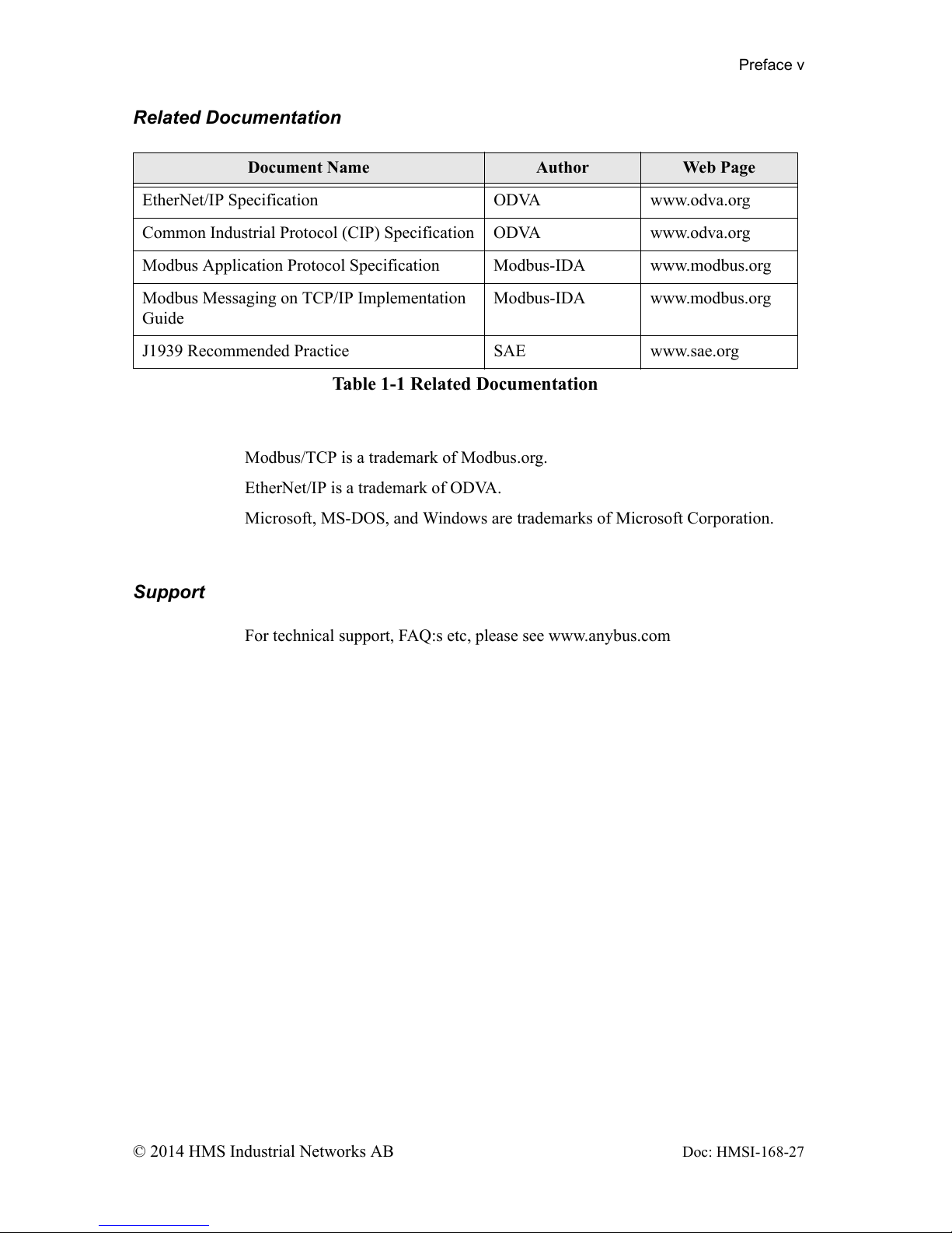
Related Documentation
Modbus/TCP is a trademark of Modbus.org.
EtherNet/IP is a trademark of ODVA.
Microsoft, MS-DOS, and Windows are trademarks of Microsoft Corporation.
Support
For technical support, FAQ:s etc, please see www.anybus.com
Document Name Author Web Page
EtherNet/IP Specification ODVA www.odva.org
Common Industrial Protocol (CIP) Specification ODVA www.odva.org
Modbus Application Protocol Specification Modbus-IDA www.modbus.org
Modbus Messaging on TCP/IP Implementation
Guide
Modbus-IDA www.modbus.org
J1939 Recommended Practice SAE www.sae.org
Table 1-1 Related Documentation
Chapter 1 Anybus X-gateway Module Description 1-1
© 2014 HMS Industrial Networks AB
Doc: HMSI-168-27
Anybus X-gateway Module Description
Overview
The Anybus Ethernet to J1939 X-gateway allows you to monitor and control data
on a J1939 heavy duty vehicle network from an Ethernet device. Data from J1939
messages are mapped to I/O table locations, making them accessible to the Ether-
net network. The EtherNet/IP and Modbus/TCP protocols are supported. The X-
gateway acts as an EtherNet/IP Adapter, allowing J1939 data to be transferred to
an EtherNet/IP Scanner device using I/O or explicit messages. The module acts
as a Modbus/TCP server, allowing J1939 data to be addressed as Modbus registers
by a Modbus/TCP client device.
Examples of applications of the Ethernet to J1939 X-gateway:
• An interface used on a diesel generator package to access engine parame-
ters from a Programmable Logic Controller (PLC).
• An on-vehicle gateway used to interface the J1939 vehicle network to an
on board industrial automation based control system.
Anybus X-gateway Module Description 1-2
© 2014 HMS Industrial Networks AB Doc: HMSI-168-27
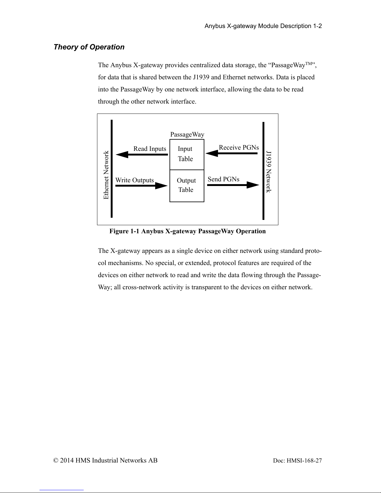
Theory of Operation
The Anybus X-gateway provides centralized data storage, the “PassageWayTM”,
for data that is shared between the J1939 and Ethernet networks. Data is placed
into the PassageWay by one network interface, allowing the data to be read
through the other network interface.
The X-gateway appears as a single device on either network using standard proto-
col mechanisms. No special, or extended, protocol features are required of the
devices on either network to read and write the data flowing through the Passage-
Way; all cross-network activity is transparent to the devices on either network.
Figure 1-1 Anybus X-gateway PassageWay Operation
Ethernet Network
J1939 Network
PassageWay
Input
Table
Output
Table
Receive PGNs
Send PGNs
Read Inputs
Write Outputs

Anybus X-gateway Module Description 1-3
© 2014 HMS Industrial Networks AB Doc: HMSI-168-27
J1939 Features
• Transmission and reception of all types of fixed-length J1939 messages,
including PDU1, PDU2, broadcast and destination specific.
• Monitoring of DM1 (active diagnostics) and DM2 (previously active
diagnostics) messages.
• Complete network address management including address claim, protec-
tion, and yield on higher priority conflict.
• Network address can be self-configurable over a range of addresses.
• J1939 Transport Protocol for transmission and reception of large mes-
sages (9 - 1785 bytes). Both connection based (RTS/CTS) and broadcast
(BAM) are supported.
• Configurable CAN bus-off reset option will reset the network interface
and attempt to return to online when a CAN bus-off condition is detected.
Ethernet Features
• Supports the EtherNet/IP protocol, Adapter Class with I/O Server, and
Message Server.
• Supports the Modbus/TCP protocol with up to 8 simultaneous connec-
tions. Conforms to the Modbus/TCP specification 1.0.
• IP address configuration may be done using DHCP/Bootp, web page, or
the Anybus X-gateway Configuration Tool.

Anybus X-gateway Module Description 1-4
© 2014 HMS Industrial Networks AB Doc: HMSI-168-27
IT-Features
• The X-gateway features a flexible file system with two security lev-
els.The size available for user files is approximately 1.4 MB.
• An FTP server provides easy file management using standard FTP clients.
• A Telnet server featuring a command line interface similar to the
MSDOS™ environment.
• A a flexible HTTP server (Web server) with Server Side Includes (SSI)
functionality. These are commands to the web server embedded in the
• HTML code. This enables the user to access the IN/OUT area using a cus-
tomizeable web page interface.
• Firmware updates of the X-gateway using the RS232 port and Anybus X-
gateway Configuration Tool.
• Email client capability.
Anybus X-gateway Module Description 1-5
© 2014 HMS Industrial Networks AB Doc: HMSI-168-27
System Requirements
The following hardware and software components are needed to use the Anybus
Ethernet to J1939 X-gateway.
Required Hardware
• Anybus X-gateway module.
• J1939 network connection.
• Ethernet cabling.
• PC or controller with access to the Ethernet network.
• 24 VDC power connection
• PC with an RS-232 communications port or USB serial adapter to execute
Anybus X-gateway Configuration Tool (BWConfig).
• RS-232 null-modem cable to connect PC running BWConfig to the Any-
bus X-gateway.
Optional Hardware
• DIN rail to mount the X-gateway.
Required Software
• Anybus X-gateway Configuration Tool software (BWConfig) to config-
ure the Anybus X-gateway.
• BWConfig requires that the PC be running Microsoft Windows 98, NT,
2000, or XP.
Anybus X-gateway Module Description 1-6
© 2014 HMS Industrial Networks AB Doc: HMSI-168-27
Hardware Description
All connections, whether power or fieldbus, to the X-gateway are made on one
end of the module. Phoenix-style connectors are provided for power and J1939
connections. An RJ-style connector is provided for Ethernet connection. There is
a 9-pin D-Subminiature connector for the auxiliary RS-232 port that is used for
device configuration. See “Installation” Page 2-1 for more details on the connec-
tors.
There is an 8 position DIP switch on the end of the module that can be used to
select a portion of a default IP address that may be used to permit an intranet con-
nection. See “Ethernet Network Configuration” Page 3-6 for more details on con-
figuring the IP address using the switches.
On the front of the X-gateway module are 6 LEDs that are used for status indica-
tion. These LEDs provide visual status for the overall module, the J1939 interface,
and the Ethernet interface. See “Anybus X-gateway LEDs” Page 10-1 for details
on how the LEDs are used.
The back of the module has a DIN rail mount to allow the module to be mounted
on a DIN rail.

Chapter 2 Installation 2-1
© 2014 HMS Industrial Networks AB
Doc: HMSI-168-27
Installation
Installation and Operation Requirements
•Power, input and output (I/O) wiring must be in accordance with Class 1, Divi-
sion 2 wiring methods - article 501-4(b) of the National Electric Code,
NFPA 70 and in accordance with local codes.
•Warning - Explosion Hazard - Substitution of components may impair suitabil-
ity for Class 1, Division 2.
•Warning - Explosion Hazard - When in hazardous locations turn off power
before replacing or wiring modules.
•Warning - Explosion Hazard - Do not disconnect equipment unless power has
been switched off or the area is known to be nonhazardous.
•Terminal tightening torque must be between 5-7 lbs-in (0.5-0.8 Nm).
•For use in Class 2 circuits only.
•Suitable for surrounding temperature of 65 degrees C maximum.
•Use 60/75 C copper wire only.
Installation 2-2
© 2014 HMS Industrial Networks AB Doc: HMSI-168-27
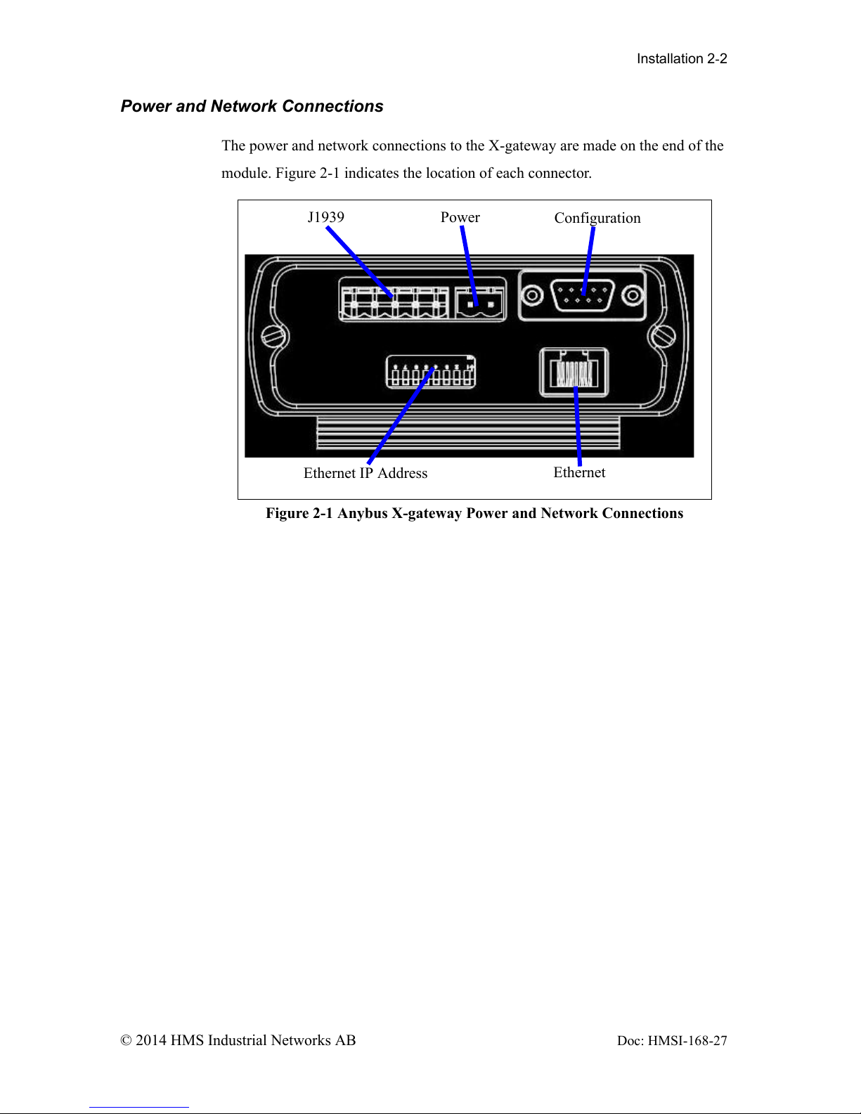
Power and Network Connections
The power and network connections to the X-gateway are made on the end of the
module. Figure 2-1 indicates the location of each connector.
Figure 2-1 Anybus X-gateway Power and Network Connections
J1939 Power
Configuration
Ethernet
Ethernet IP Address

Installation 2-3
© 2014 HMS Industrial Networks AB Doc: HMSI-168-27
Connecting Power
The power connection is a 2-pin terminal block located on the end of the module.
The female terminal block connector is provided with the X-Gateway. Connec-
tions to be made are illustrated in Figure 2-2.
The X-gateway requires 24 volts DC power. The module will start immediately
when power is applied (There is no On/Off switch on the module).
Figure 2-2 Power Connection
24VDC Common
24 VDC +

Installation 2-4
© 2014 HMS Industrial Networks AB Doc: HMSI-168-27
Connecting J1939
The J1939 network connection is a 5-pin terminal block located next to the power
connection on the end of the module. The female terminal block connector is pro-
vided with the X-gateway. Connections to be made are illustrated in Figure 2-3.
The CAN High and Low signal lines should be connected to the CAN High and
Low connections respectively on all devices on the network. The signal lines
should not be swapped on any device connections.
Note: The 24VDC terminals on pins 1 and 5 are physically connected to the
power on the 2-pin power connector. The module may alternatively be powered
from these pins.
Figure 2-3 J1939 Connection
24VDC +
24VDC Common
J1939 CAN High
J1939 CAN Low
J1939 CAN Shield

Installation 2-5
© 2014 HMS Industrial Networks AB Doc: HMSI-168-27
Connecting to Ethernet
The Ethernet connection uses a standard RJ45 connector (not provided). This is
plugged into the socket on the end of the module.
Configuration Port Connector
The configuration port is the 9-pin D-Subminiature female connector on the end
of the X-gateway. The connector has a standard RS-232 DTE pin configuration.
The connections to be made as shown below.
The X-gateway is connected to a PC for configuration using a null-modem cable
and a 9 pole dsub gender-shifter (male-male). A null-modem cable has pins 2 and
3 swapped so that the PC’s Transmit line is connected to the X-gateway’s Receive
line, and the PC’s Receive line is connected to the X-gateway’s Transmit line.
Note: The Anybus X-gateway does not make use of the modem control signals
specified for a DTE connector. Connecting the module through devices, such as
isolation modules, which assume control of these lines may cause the BWConfig
communications to be unreliable.
Pin Connection
2 Receive Data
3 Transmit Data
5 Signal Ground
Chapter 3 Configuration 3-1
© 2014 HMS Industrial Networks AB
Doc: HMSI-168-27
Configuration
This chapter describes how the Anybus Ethernet to J1939 X-gateway is config-
ured using the Anybus X-gateway Configuration Tool (BWConfig). Detailed
descriptions of each configurable parameter in the gateway are provided as well as
how they are set in the tool.
The next chapter walks the reader through the configuration of an example appli-
cation to illustrate how the configurable parameters are used in a real-world appli-
cation.
Anybus X-gateway Configuration Tool (BWConfig)
The Anybus X-gateway Configuration Tool allows you to configure the parame-
ters associated with the Ethernet and J1939 network interfaces as well as to set up
the contents and layout of the I/O table.
BWConfig is a Microsoft Windows application that communicates with a X-gate-
way over a standard RS-232 serial link using the PC serial port or USB serial
adapter. BWConfig is compatible with Microsoft Windows 98, NT, 2000, and XP.
Installing the Tool
Install BWConfig from the CD by running Setup.exe which is found in the CD's
root directory.
If you have downloaded BWConfig from the web site, unzip the downloaded file
into a temporary directory and run Setup.exe which is found in the temporary
directory.
Configuration 3-2
© 2014 HMS Industrial Networks AB Doc: HMSI-168-27
Connecting to the X-gateway Module
Connect the PC running BWConfig to the X-gateway module using a standard
Null-Modem (pins 2 and 3 swapped) serial cable between the PC serial port or
USB adapter and the 9-pin D-Sub connector on the module. It does not matter
which PC serial port you use, BWConfig will scan each available port and detect
the connection automatically. No serial port configuration is required; BWConfig
will automatically set the baud rate.
Starting the Tool
Launch BWConfig from the Anybus X-gateway Configuration folder in the Win-
dows Start Menu.
When BWConfig is started, it will attempt to locate a X-gateway module on one
of the PC serial ports. If a module is found, the status area of the tool will be
updated to show the module type and status of the module that was located.
If a module is not connected to the PC, or is powered off, when the tool is started,
the status area will indicate that no module was detected. Make sure that the mod-
ule is powered and the connection is made, then press the Refresh button on the
BWConfig tool bar; this will cause the tool to rescan the serial ports for a module.
Configuration 3-3
© 2014 HMS Industrial Networks AB Doc: HMSI-168-27
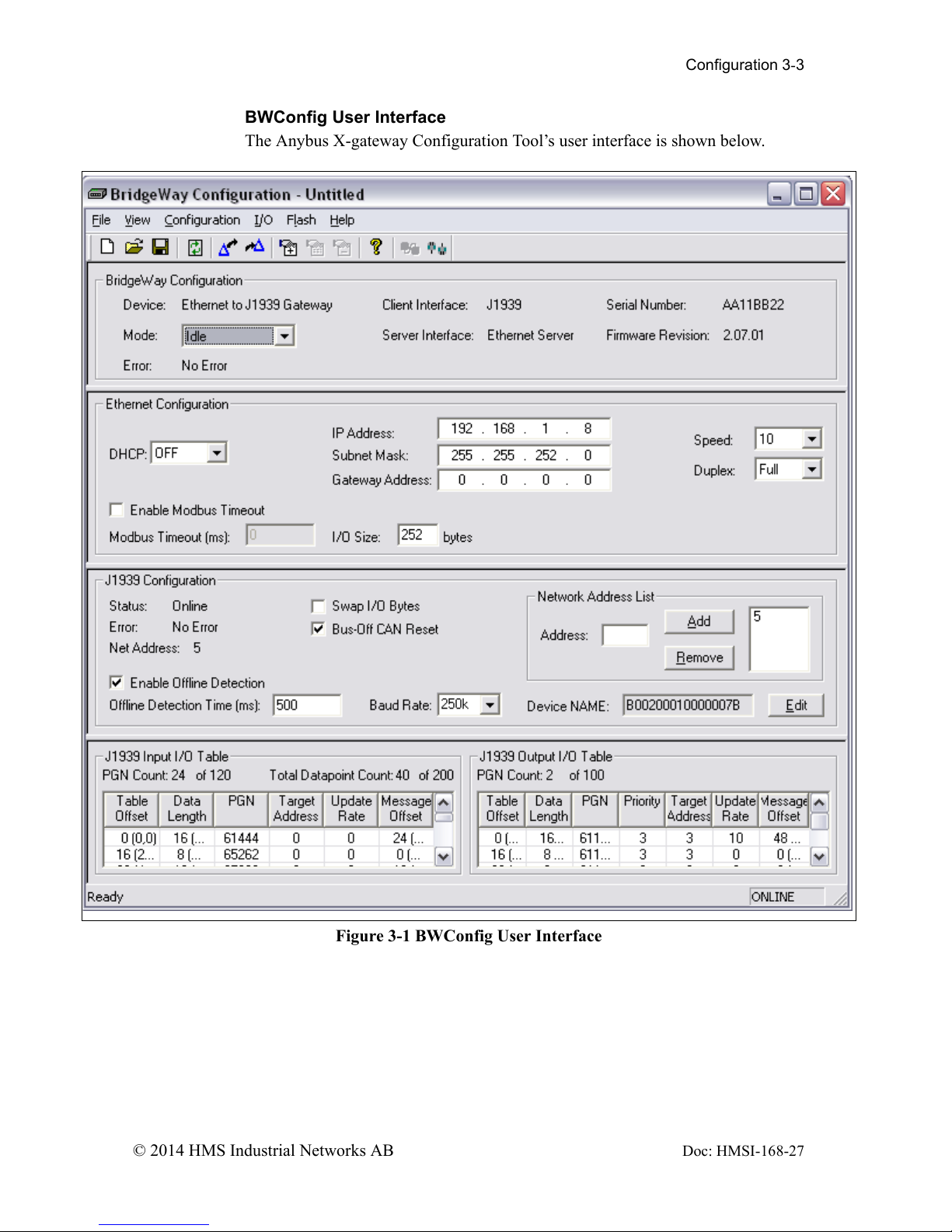
BWConfig User Interface
The Anybus X-gateway Configuration Tool’s user interface is shown below.
Figure 3-1 BWConfig User Interface
Configuration 3-4
© 2014 HMS Industrial Networks AB Doc: HMSI-168-27
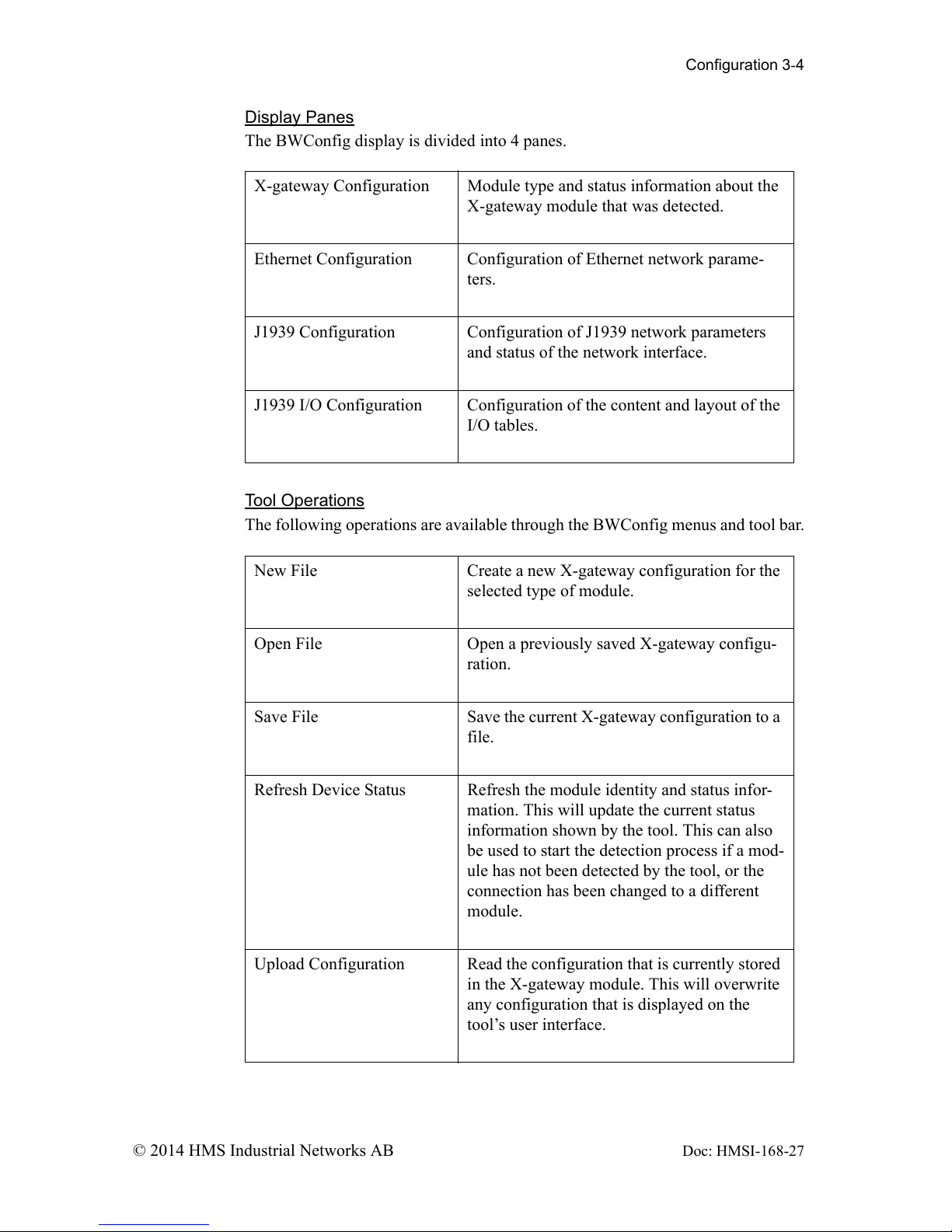
Display Panes
The BWConfig display is divided into 4 panes.
Tool Operations
The following operations are available through the BWConfig menus and tool bar.
X-gateway Configuration Module type and status information about the
X-gateway module that was detected.
Ethernet Configuration Configuration of Ethernet network parame-
ters.
J1939 Configuration Configuration of J1939 network parameters
and status of the network interface.
J1939 I/O Configuration Configuration of the content and layout of the
I/O tables.
New File Create a new X-gateway configuration for the
selected type of module.
Open File Open a previously saved X-gateway configu-
ration.
Save File Save the current X-gateway configuration to a
file.
Refresh Device Status Refresh the module identity and status infor-
mation. This will update the current status
information shown by the tool. This can also
be used to start the detection process if a mod-
ule has not been detected by the tool, or the
connection has been changed to a different
module.
Upload Configuration Read the configuration that is currently stored
in the X-gateway module. This will overwrite
any configuration that is displayed on the
tool’s user interface.
Configuration 3-5
© 2014 HMS Industrial Networks AB Doc: HMSI-168-27
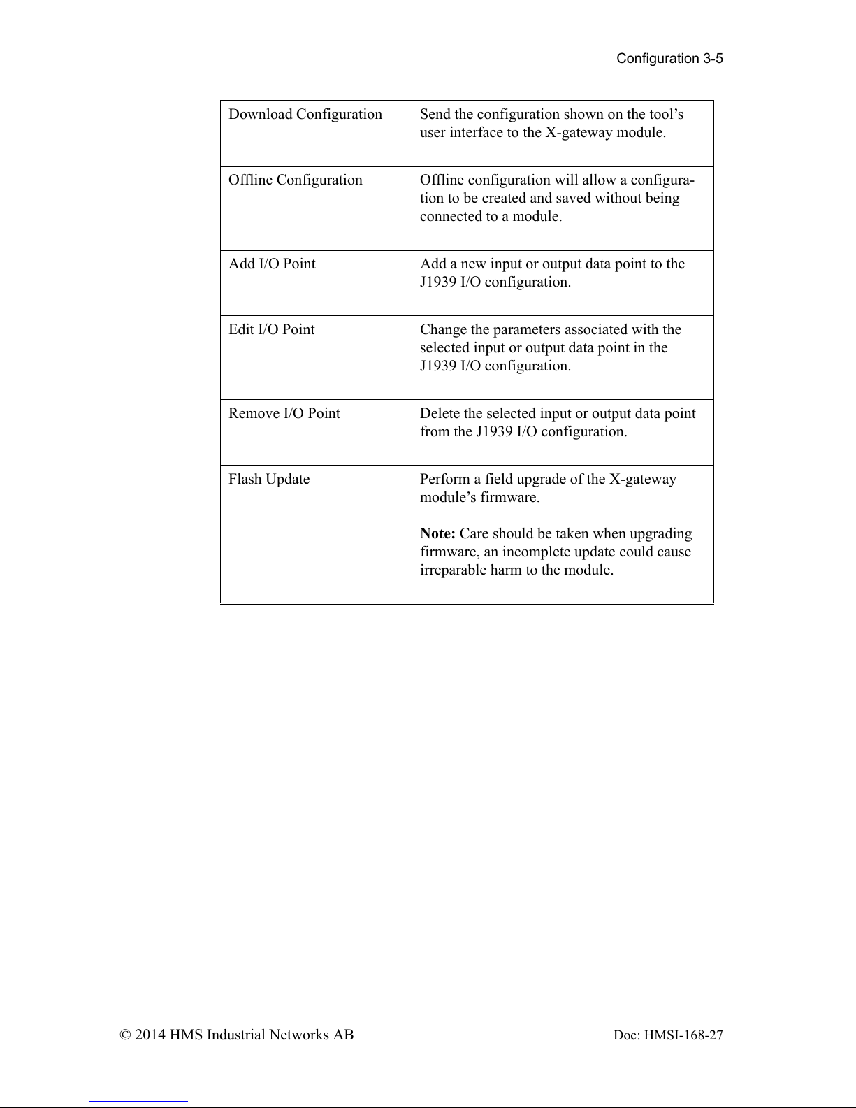
Download Configuration Send the configuration shown on the tool’s
user interface to the X-gateway module.
Offline Configuration Offline configuration will allow a configura-
tion to be created and saved without being
connected to a module.
Add I/O Point Add a new input or output data point to the
J1939 I/O configuration.
Edit I/O Point Change the parameters associated with the
selected input or output data point in the
J1939 I/O configuration.
Remove I/O Point Delete the selected input or output data point
from the J1939 I/O configuration.
Flash Update Perform a field upgrade of the X-gateway
module’s firmware.
Note: Care should be taken when upgrading
firmware, an incomplete update could cause
irreparable harm to the module.
Configuration 3-6
© 2014 HMS Industrial Networks AB Doc: HMSI-168-27
Ethernet Network Configuration
Several methods may be used to set the IP Address. These methods include the
Anybus X-gateway Configuration Tool, IP Address Configuration Switch, DHCP/
Bootp protocol, web browser, and the ARP protocol.
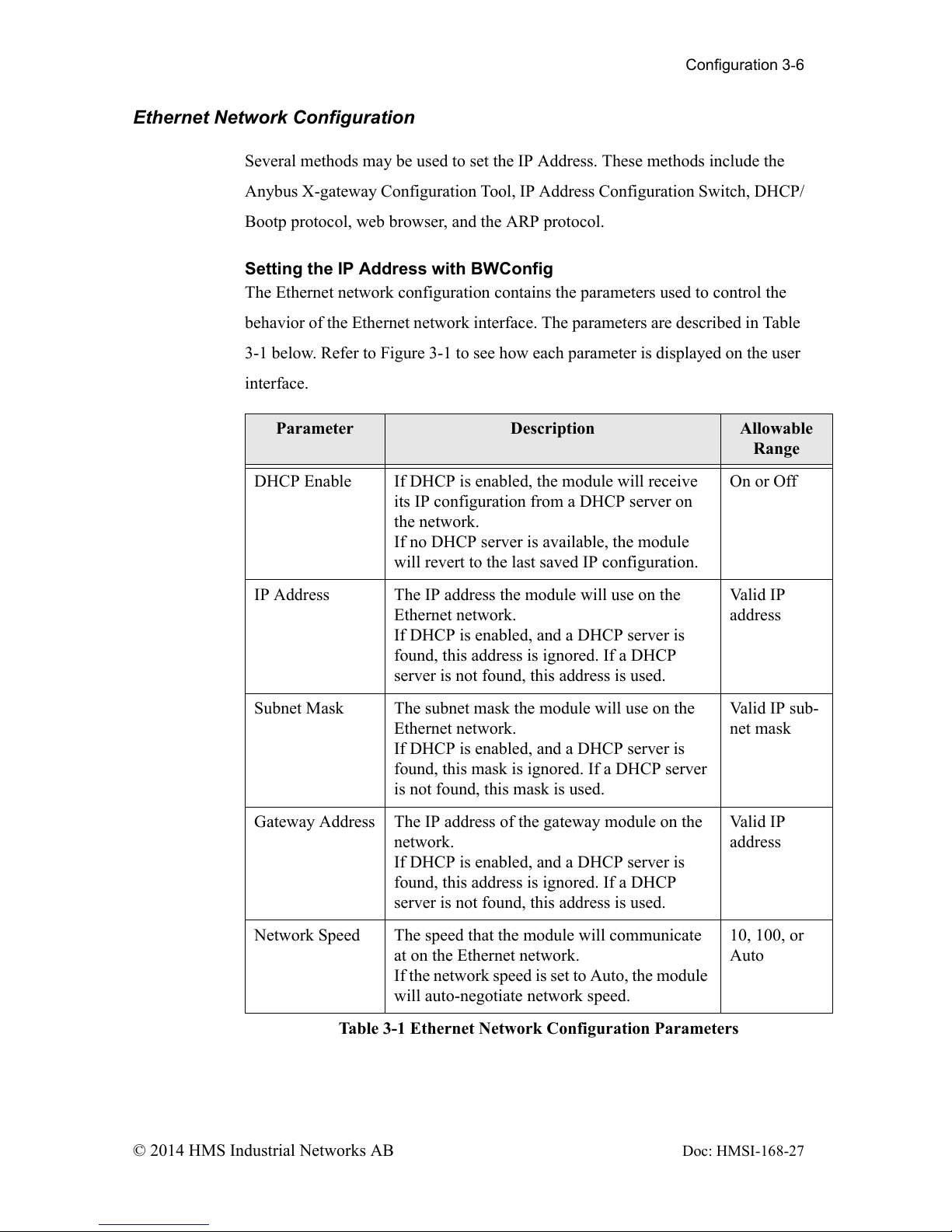
Setting the IP Address with BWConfig
The Ethernet network configuration contains the parameters used to control the
behavior of the Ethernet network interface. The parameters are described in Table
3-1 below. Refer to Figure 3-1 to see how each parameter is displayed on the user
interface.
Parameter Description Allowable
Range
DHCP Enable If DHCP is enabled, the module will receive
its IP configuration from a DHCP server on
the network.
If no DHCP server is available, the module
will revert to the last saved IP configuration.
On or Off
IP Address The IP address the module will use on the
Ethernet network.
If DHCP is enabled, and a DHCP server is
found, this address is ignored. If a DHCP
server is not found, this address is used.
Valid IP
address
Subnet Mask The subnet mask the module will use on the
Ethernet network.
If DHCP is enabled, and a DHCP server is
found, this mask is ignored. If a DHCP server
is not found, this mask is used.
Valid IP sub-
net mask
Gateway Address The IP address of the gateway module on the
network.
If DHCP is enabled, and a DHCP server is
found, this address is ignored. If a DHCP
server is not found, this address is used.
Valid IP
address
Network Speed The speed that the module will communicate
at on the Ethernet network.
If the network speed is set to Auto, the module
will auto-negotiate network speed.
10, 100, or
Auto
Table 3-1 Ethernet Network Configuration Parameters
Configuration 3-7
© 2014 HMS Industrial Networks AB Doc: HMSI-168-27
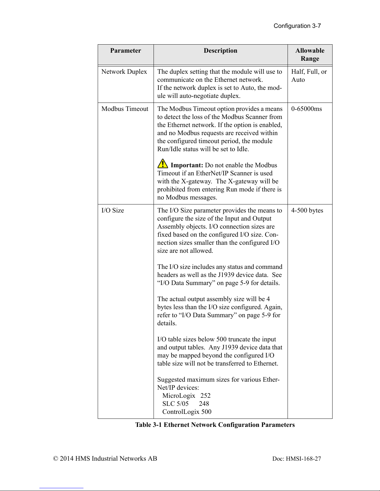
Network Duplex The duplex setting that the module will use to
communicate on the Ethernet network.
If the network duplex is set to Auto, the mod-
ule will auto-negotiate duplex.
Half, Full, or
Auto
Modbus Timeout The Modbus Timeout option provides a means
to detect the loss of the Modbus Scanner from
the Ethernet network. If the option is enabled,
and no Modbus requests are received within
the configured timeout period, the module
Run/Idle status will be set to Idle.
Important: Do not enable the Modbus
Timeout if an EtherNet/IP Scanner is used
with the X-gateway. The X-gateway will be
prohibited from entering Run mode if there is
no Modbus messages.
0-65000ms
I/O Size The I/O Size parameter provides the means to
configure the size of the Input and Output
Assembly objects. I/O connection sizes are
fixed based on the configured I/O size. Con-
nection sizes smaller than the configured I/O
size are not allowed.
The I/O size includes any status and command
headers as well as the J1939 device data. See
“I/O Data Summary” on page 5-9 for details.
The actual output assembly size will be 4
bytes less than the I/O size configured. Again,
refer to “I/O Data Summary” on page 5-9 for
details.
I/O table sizes below 500 truncate the input
and output tables. Any J1939 device data that
may be mapped beyond the configured I/O
table size will not be transferred to Ethernet.
Suggested maximum sizes for various Ether-
Net/IP devices:
MicroLogix 252
SLC 5/05 248
ControlLogix 500
4-500 bytes
Parameter Description Allowable
Range
Table 3-1 Ethernet Network Configuration Parameters

Configuration 3-8
© 2014 HMS Industrial Networks AB Doc: HMSI-168-27
Setting the IP Address with the Configuration Switch
If DHCP/BootP is not enabled or a server is not found and the Configuration
Switch is non zero, on power up the value of the switch is used to form an IP
Address. The switch represents the binary value of the last byte in the 4 byte IP
address. In this case it is n.
IP address: 192.168.1.n
Subnet mask: 255.255.255.0
Gateway address: 0.0.0.0 (No gateway set)
This is a private address and can only be used on a local intranet. In such a case a
Web Browser such as Microsoft’s Internet Explorer can be used to access the X-
gateway’s web page which allows changing the IP Address, Subnet mask, and
GateWay address settings.
Note: A non-zero DIP switch setting will override any other Ethernet configura-
tion that is done.
DIP Switch Example
The switches are set to 00010100 (20 decimal) (The switch position is shown in
White in the diagram.)
The IP address of the module will be set to 192.168.1.20.
Note: The numbers on the switches on the IP configuration DIP switch do NOT
correspond to bit locations in the address value. In fact, they are reversed. i.e. bit 0
is set by switch 8.
Figure 3-2 IP Configuration DIP Switch

Configuration 3-9
© 2014 HMS Industrial Networks AB Doc: HMSI-168-27
Setting the IP Address Using DHCP/BootP
When DHCP/BootP is enabled and a DHCP or BootP server is found, the IP
address, Subnet mask, and Gateway address is automatically configured by the
DHCP/BootP server. It can be enabled using BWConfig or the X-gateway’s Set-
tings web page.
Note: The use of DHCP is the default configuration for the Anybus X-gateway as
shipped.
Configuration 3-10
© 2014 HMS Industrial Networks AB Doc: HMSI-168-27
Setting the IP Address Using Address Resolution Protocol (ARP)
The module’s IP address can be changed using the ARP command from a PC. The
new IP address will be stored in non-volatile memory. ARP requires the module’s
Ethernet MAC Address that is printed on a label on the back of the module.
Note: ARP cannot be used to change the subnet mask and gateway address of the
X-gateway. These can be configured using the X-gateway’s Settings web page.
Switch all 8 switches of the IP Configuration DIP switch to the ON position.
Note: The ARP/Ping capability is disabled unless all switches are ON.
On a PC connected to the X-gateway on Ethernet bring up an MS DOS™ window
and type:
arp -s <IP address> <MAC address>
The arp -s command will store the IP and MAC addresses in the PC’s ARP table.
Next type:
ping <IP address>
When the Ping command is executed, the PC sends this information to the module
using the MAC address. The module detects that it was addressed with the correct
MAC address and adopts the IP address sent by the PC.
Next type:
arp -d <IP address>
The arp -d will remove the static route from the PC’s ARP table.
Switch all 8 switches of the IP Configuration DIP switch to the OFF position to
disable the feature.
This method can be used to reconfigure a module that has been previously config-
ured, or even to reconfigure modules outside the host’s subnet.

Configuration 3-11
© 2014 HMS Industrial Networks AB Doc: HMSI-168-27
Arp/Ping Example:
The following commands will set the IP address of a X-gateway with MAC
address 00-30-11-02-00-5E to 65.106.34.252.
arp -s 65.106.34.252 00-30-11-02-00-5e
ping 65.106.34.252
arp -d 65.106.34.252

Configuration 3-12
© 2014 HMS Industrial Networks AB Doc: HMSI-168-27
Setting the IP Address Using the Web Page
The ethernet addresses can also be configured using the Status and Settings web
page resident on the X-gateway. The Status and Settings web page appears as
shown below.
Figure 3-3 Status and Settings Web Page

Configuration 3-13
© 2014 HMS Industrial Networks AB Doc: HMSI-168-27
The IP address, subnet mask, and default gateway address are displayed in the edit
boxes on the web page. Changing any values and clicking the Submit Values but-
ton will set the addresses in the X-gateway. Note that a power cycle or module
reset is required for the changes to take effect.
Note: If your web browser is configured to cache web pages, it may appear that
the Anybus X-gateway has not changed address after you power cycle the mod-
ule. Make sure that the browsers settings are configured to always reload pages.
On Internet Explorer this is done in the Temporary Internet Files Settings dialog
by selecting the “Every Visit” option for when the browser should check for page
changes.
 Loading...