

HMS Anybus X-gateway CANopen PROFINET User Manual

HALMSTAD • CHICAGO • KARLSRUHE • TOKYO • BEIJING • MILANO • MULHOUSE • COVENTRY • PUNE • COPENHAGEN
HMS Industrial Networks
Mailing address: Box 4126, 300 04 Halmstad, Sweden
Visiting address: Stationsgatan 37, Halmstad, Sweden
Connecting Devices
TM
E-mail: info@hms-networks.com
www.anybus.com
User Manual
Anybus® X-gateway CANopen
PROFINET
Doc.Id. HMSI-168-91
Rev. 2.10
Important User Information
This document is intended to provide a good understanding of the functionality offered by the Anybus X-gateway
CANopen - PROFINET.
The reader of this document is expected to be familiar with high level software design, and communication
systems in general. The use of advanced CANopen specific functionality may require in-depth knowledge in
CANopen networking internals and/or information from the official CANopen specifications. In such cases, the
people responsible for the implementation of this product should either obtain the CANopen specification to gain
sufficient knowledge or limit their implementation in such a way that this is not necessary. Also knowledge of
PROFINET is expected.
Liability
Every care has been taken in the preparation of this manual. Please inform HMS Industrial Networks AB of any
inaccuracies or omissions. The data and illustrations found in this document are not binding. We, HMS Industrial
Networks AB, reserve the right to modify our products in line with our policy of continuous product development.
The information in this document is subject to change without notice and should not be considered as a commit-
ment by HMS Industrial Networks AB. HMS Industrial Networks AB assumes no responsibility for any errors that
may appear in this document.
There are many applications of this product. Those responsible for the use of this device must ensure that all the
necessary steps have been taken to verify that the applications meet all performance and safety requirements in-
cluding any applicable laws, regulations, codes, and standards.
HMS Industrial Networks AB will under no circumstances assume liability or responsibility for any problems that
may arise as a result from the use of undocumented features, timing, or functional side effects found outside the
documented scope of this product. The effects caused by any direct or indirect use of such aspects of the product
are undefined, and may include e.g. compatibility issues and stability issues.
The examples and illustrations in this document are included solely for illustrative purposes. Because of the many
variables and requirements associated with any particular implementation, HMS Industrial Networks AB cannot
assume responsibility for actual use based on these examples and illustrations.
Intellectual Property Rights
HMS Industrial Networks AB has intellectual property rights relating to technology embodied in the product de-
scribed in this document. These intellectual property rights may include patents and pending patent applications
in the US and other countries.
Trademark Acknowledgements
Anybus ® is a registered trademark of HMS Industrial Networks AB. All other trademarks are the property of their
respective holders.
WARNING: This is a class A product. In a domestic environment this product may cause radio interference in
which case the user may be required to take adequate measures.
ESD Note: This product contains ESD (Electrostatic Discharge) sensitive parts that may be damaged if ESD
control procedures are not followed. Static control precautions are required when handling the prod-
uct. Failure to observe this may cause damage to the product.
WARNING: DO NOT REMOVE OR REPLACE USB CONNECTOR WHILE CIRCUIT IS LIVE UNLESS THE
AREA IS KNOWN TO BE FREE OF IGNITIBLE CONCENTRATIONS OF FLAMMABLE GASES OR
VAPORS.
Anybus X-gateway CANopen - PROFINET User Manual
Rev 2.10
Copyright© HMS Industrial Networks AB
Doc: HMSI-168-91
Important User Information
Liability........................................................................................................................................... 1
Intellectual Property Rights............................................................................................................... 1
Trademark Acknowledgements......................................................................................................... 1
Preface About This Document
Related Documents ..................................................................................................................................1
Document History ...................................................................................................................................1
Conventions & Terminology .................................................................................................................. 1
Sales and Support ..................................................................................................................................... 1
Chapter 1 Anybus X-gateway CANopen - PROFINET
Introduction .............................................................................................................................................. 2
Features ......................................................................................................................................................3
Functional Overview................................................................................................................................ 4
Data Exchange.......................................................................................................................................... 4
Chapter 2 About the Anybus X-gateway CANopen
External View............................................................................................................................................6
Status LEDs .............................................................................................................................................. 7
Primary Network ...................................................................................................................................... 8
PROFINET Connector (Network Access Port).............................................................................. 8
Secondary Network.................................................................................................................................. 9
CANopen Connector....................................................................................................................... 9
Configuration Switches ..................................................................................................................... 9
USB Connector....................................................................................................................................... 10
Power Connector............................................................................................................................. 10
Hardware Installation............................................................................................................................. 11
CANopen Electronic Data Sheet (EDS) ............................................................................................ 12
PROFINET Generic Station Description (GSD file) ...................................................................... 12
Chapter 3 Getting Started
Chapter 4 CANopen Fieldbus Functionality
Supported Fieldbus Services................................................................................................................. 14
Chapter 5 Configuration
Module Identification ............................................................................................................................15
CANopen Master/Slave Configuration ..............................................................................................16
Table of Contents
Table of Contents
II
Doc.Id. HMSI-168-91
Anybus X-gateway CANopen
Doc.Rev. 2.10
Secondary CANopen Network Configuration .................................................................................. 17
LSS Routine.................................................................................................................................. 17
Configuration of the PROFINET Interface...................................................................................... 18
Data Exchange.............................................................................................................................. 18
PROFINET IO Data ................................................................................................................. 18
........................................................................................................... Modbus/TCP (Read-Only)19
Configuration .................................................................................................................................20
IP Settings .....................................................................................................................................20
Enabling Data Exchange....................................................................................................................... 22
Chapter 6 CANopen Module Specification
NMT State Machine............................................................................................................................... 23
Data Exchange........................................................................................................................................24
Control Word ................................................................................................................................25
Status Word ..................................................................................................................................26
Example........................................................................................................................................28
PDO Functionality........................................................................................................................ 29
LSS Services............................................................................................................................................. 30
Error Control ..........................................................................................................................................31
Heartbeat Mechanism .................................................................................................................... 31
Node Guarding.............................................................................................................................. 31
Emergency Object (EMCY)........................................................................................................... 31
Chapter 7 CANopen Supported Objects
Static Data Types....................................................................................................................................32
Communication Profile Area................................................................................................................ 32
DS301 Communication Profile Objects.......................................................................................... 32
Configuration Manager .................................................................................................................. 34
Network Management Objects ....................................................................................................... 35
Vendor Specific Objects........................................................................................................................40
Transmit Buffer ............................................................................................................................. 41
Receive Buffer ................................................................................................................................. 42
I/O Buffer Addresses and Object Dictionary Indices Relation ........................................................ 43
General Fieldbus Parameters.......................................................................................................... 44
PROFINET Specific Parameters.................................................................................................. 44
Appendix A Technical Specification
Protective Earth (PE) Requirements................................................................................................... 45
Power Supply ..........................................................................................................................................45
Environmental Specification ................................................................................................................ 45
Temperature................................................................................................................................... 45
Relative Humidity.......................................................................................................................... 45
EMC (CE) Compliance ......................................................................................................................... 46
UL and ATEX Certification ................................................................................................................. 46

III
Doc.Id. HMSI-168-91
Anybus X-gateway CANopen
Doc.Rev. 2.10
Appendix B Status LED Timing Diagrams
Appendix C CANopen Emergency Codes
Appendix D Enabling Data Exchange

Doc.Id. HMSI-168-91
Anybus X-gateway CANopen to PROFINET
Doc.Rev. 2.10
Preface
P. About This Document
For more information, documentation etc., please visit www.anybus.com
P.1 Related Documents
P.2 Document History
Revision List
P.3 Conventions & Terminology
The following conventions are used throughout this manual:
• Numbered lists provide sequential steps
• Bulleted lists provide information, not procedural steps
• The terms ‘Anybus’ or ‘module’ refers to the Anybus X-gateway module.
• Hexadecimal values are written in the format NNNNh, where NNNN is the hexadecimal value.
• A byte always consists of 8 bits
P.4 Sales and Support
For general contact information and support, please refer to the contact and support pages at
www.anybus.com
Document Author
CiA Draft Standard 301 v4.2 CAN in Automation
CiA Draft Standard Proposal 302 Part 1-5 CAN in Automation
PROFINET IO Specification PROFIBUS Nutzerorganisation e.V. (PNO)
PROFINET Technology and Application PROFIBUS Nutzerorganisation e.V. (PNO)
PROFIBUS Guideline, Identification & Maintenance Functions PROFIBUS Nutzerorganisation e.V. (PNO)
Open Modbus/TCP Specification Schneider Automation
Revision Date Author(s) Chapter(s) Description
1.00 2010-01-17 KeL - First official release
1.01 2011-02-04 KeL - Minor corrections and updates
1.02 2011-03-29 KeL 6, 7 Minor corrections
2.00 2011-12-20 KeL All General rewrite
2.01 2013-01-11 KeL 6 Minor correction
2.10 Nov 2014 SDa Multiple Removed references to PORT configuration software
Doc.Id. HMSI-168-91
Anybus X-gateway CANopen - PROFINET
Doc.Rev. 2.10
Chapter 1
1. Anybus X-gateway CANopen - PROFINET
1.1 Introduction
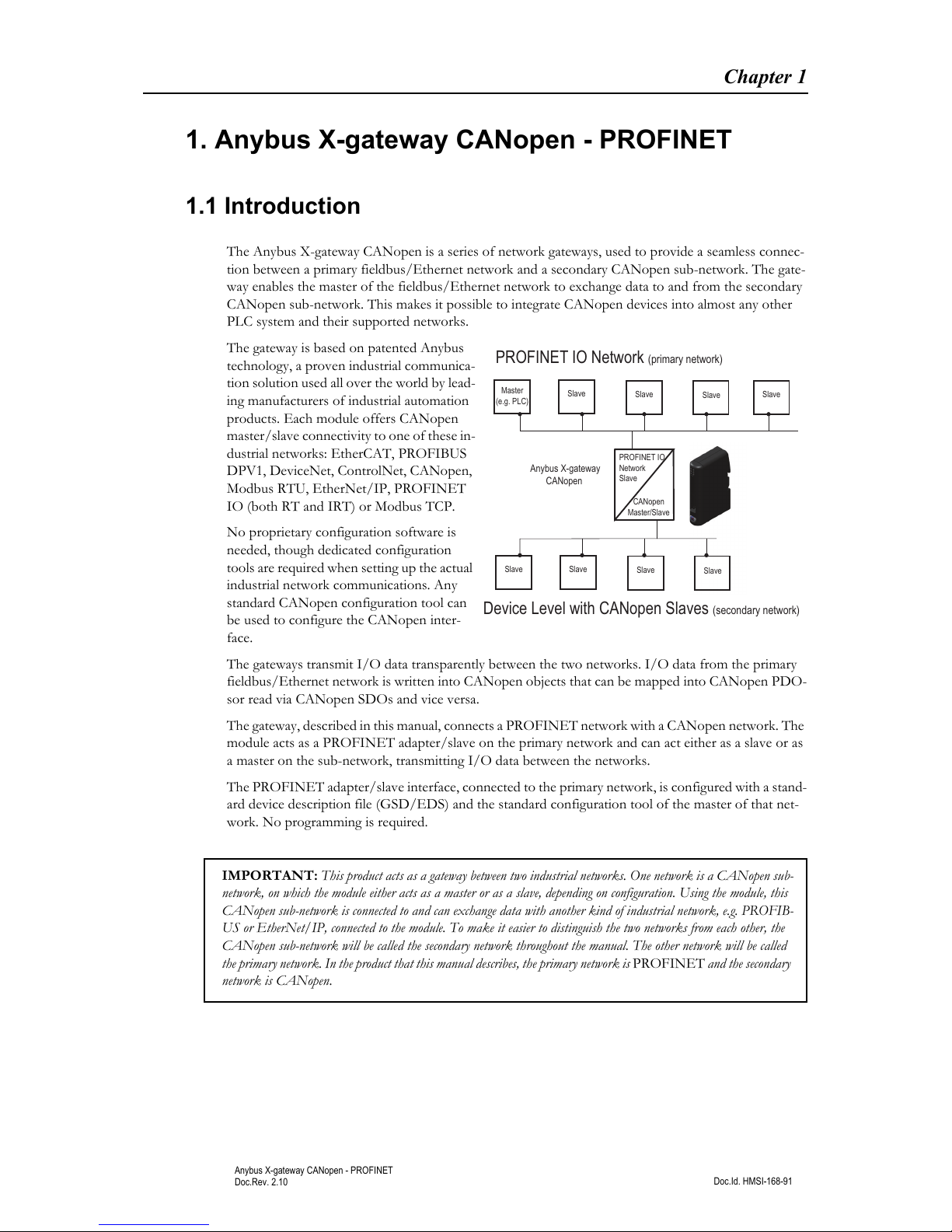
The Anybus X-gateway CANopen is a series of network gateways, used to provide a seamless connec-
tion between a primary fieldbus/Ethernet network and a secondary CANopen sub-network. The gate-
way enables the master of the fieldbus/Ethernet network to exchange data to and from the secondary
CANopen sub-network. This makes it possible to integrate CANopen devices into almost any other
PLC system and their supported networks.
The gateway is based on patented Anybus
technology, a proven industrial communica-
tion solution used all over the world by lead-
ing manufacturers of industrial automation
products. Each module offers CANopen
master/slave connectivity to one of these in-
dustrial networks: EtherCAT, PROFIBUS
DPV1, DeviceNet, ControlNet, CANopen,
Modbus RTU, EtherNet/IP, PROFINET
IO (both RT and IRT) or Modbus TCP.
No proprietary configuration software is
needed, though dedicated configuration
tools are required when setting up the actual
industrial network communications. Any
standard CANopen configuration tool can
be used to configure the CANopen inter-
face.
The gateways transmit I/O data transparently between the two networks. I/O data from the primary
fieldbus/Ethernet network is written into CANopen objects that can be mapped into CANopen PDO-
sor read via CANopen SDOs and vice versa.
The gateway, described in this manual, connects a PROFINET network with a CANopen network. The
module acts as a PROFINET adapter/slave on the primary network and can act either as a slave or as
a master on the sub-network, transmitting I/O data between the networks.
The PROFINET adapter/slave interface, connected to the primary network, is configured with a stand-
ard device description file (GSD/EDS) and the standard configuration tool of the master of that net-
work. No programming is required.
Device Level with CANopen Slaves (secondary network)
PROFINET IO Network (primary network)
Master
(e.g. PLC)
Slave
Slave
Slave
Slave
Slave Slave
Slave
Slave
Anybus X-gateway
CANopen
CANopen
Master/Slave
PROFINET IO
Network
Slave
IMPORTANT: This product acts as a gateway between two industrial networks. One network is a CANopen sub-
network, on which the module either acts as a master or as a slave, depending on configuration. Using the module, this
CANopen sub-network is connected to and can exchange data with another kind of industrial network, e.g. PROFIB-
US or EtherNet/IP, connected to the module. To make it easier to distinguish the two networks from each other, the
CANopen sub-network will be called the secondary network throughout the manual. The other network will be called
the primary network. In the product that this manual describes, the primary network is PROFINET and the secondary
network is CANopen.
Anybus X-gateway CANopen - PROFINET 3
Doc.Id. HMSI-168-91
Anybus X-gateway CANopen - PROFINET
Doc.Rev. 2.10
1.2 Features
The Anybus CANopen X-gateway acts as an intelligent link between two industrial networks. On the
secondary CANopen sub-network, it can perform either as a master (manager) or as a slave (server), de-
pending on configuration, while it always will act as a slave on the primary fieldbus/Ethernet side. The
implementation is based on HMS NP30 network microprocessor and is certified by CAN in Automation
(CIA) for full conformance to the CANopen DS 301 v4.0.2 standard.
CANopen (sub-network, secondary network)
• CANopen master (manager) and slave functionality
• Connects up to 126 CANopen slave nodes
• Complies to the CANopen communication profile DS301 4.2 and DSP302 (part 1-5)
• Supports cyclic and acyclic synchronous as well as COS (change of state) PDO message types
• 20 kbps... 1 Mbps operation
• Heartbeat and node guarding mechanisms
• Sync objects
• 128 receive and 128 transmit PDOs available
• Up to 510 bytes of cyclic data in each direction (PDO)
PROFINET Features (primary network)
General
• 100 Mbit operation in full duplex
• Built in file system with per-user security framework
• Modbus/TCP Server (Read-only)
Supported PROFINET Features
• Real-Time (RT) communication
• Cyclic data exchange (2 - 512 ms cycle time)
• Acyclic Data exchange (Record Data Requests, not supported by the Anybus X-gateway CAN-
open)
• Up to 64 slots / 1 sub-slot
• Up to 512 bytes of I/O in each direction
• DCP support (Discovery and Configuration Protocol)
• LLDP (Linked Layer Discovery Protocol)
Anybus X-gateway CANopen - PROFINET 4
Doc.Id. HMSI-168-91
Anybus X-gateway CANopen - PROFINET
Doc.Rev. 2.10
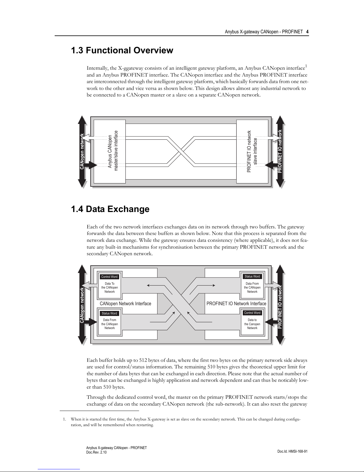
1.3 Functional Overview
Internally, the X-ggateway consists of an intelligent gateway platform, an Anybus CANopen interface1
and an Anybus PROFINET interface. The CANopen interface and the Anybus PROFINET interface
are interconnected through the intelligent gateway platform, which basically forwards data from one net-
work to the other and vice versa as shown below. This design allows almost any industrial network to
be connected to a CANopen master or a slave on a separate CANopen network.
1.4 Data Exchange
Each of the two network interfaces exchanges data on its network through two buffers. The gateway
forwards the data between these buffers as shown below. Note that this process is separated from the
network data exchange. While the gateway ensures data consistency (where applicable), it does not fea-
ture any built-in mechanisms for synchronisation between the primary PROFINET network and the
secondary CANopen network.
Each buffer holds up to 512 bytes of data, where the first two bytes on the primary network side always
are used for control/status information. The remaining 510 bytes gives the theoretical upper limit for
the number of data bytes that can be exchanged in each direction. Please note that the actual number of
bytes that can be exchanged is highly application and network dependent and can thus be noticably low-
er than 510 bytes.
Through the dedicated control word, the master on the primary PROFINET network starts/stops the
exchange of data on the secondary CANopen network (the sub-network). It can also reset the gateway
1. When it is started the first time, the Anybus X-gateway is set as slave on the secondary network. This can be changed during configu-
ration, and will be remembered when restarting.
PROFINET IO network
CANopen network
Anybus CANopen
master/slave interface
PROFINET IO network
slave interface
PROFINET IO Network InterfaceCANopen Network Interface
PROFINET IO network
CANopen network
Data To
the CANopen
Network
Data From
the CANopen
Network
Data From
the CANopen
Network
Data to
the Canopen
Network
Status Word
Status Word
Control Word
Control Word

Anybus X-gateway CANopen - PROFINET 5
Doc.Id. HMSI-168-91
Anybus X-gateway CANopen - PROFINET
Doc.Rev. 2.10
if needed. The master on the primary PROFINET network can see the status of the secondary CAN-
open network in the corresponding status word.
The amount of data that shall be exchanged, and the use of the control- and status functionality, is spec-
ified separately for each application. This means that even though up to 510 bytes of data can be for-
warded to an interface, the amount of data that will actually be exchanged on the primary PROFINET
network is determined by settings of the secondary CANopen network, with consideration taken to the
limits of the interface.
The available control- and status functionality is described in “Data Exchange” on page 24. Also note
that the terminology and definitions used for different types of data vary greatly between different net-
working systems. All data transported through the Anybus X-gateway CANopen is fast, cyclic data and
is simply referred to as ‘I/O Data’ in this document.

Doc.Id. HMSI-168-91
Anybus X-gateway CANopen - PROFINET
Doc.Rev. 2.10
Chapter 2
2. About the Anybus X-gateway CANopen
2.1 External View
A: Status LEDs
See also...
- “Status LEDs” on page 7
B: Primary Network Connectors and Switches
This connector (connectors) and, if available, these
switches are used to connect the Anybus X-gateway
CANopen module to the primary PROFINET net-
work and to configure that interface. They are de-
scribed in “Primary Network” on page 8.
C: USB connector
This connector simulates a COM-port, used for soft-
ware upgrade of the module. Please note that this
connector can not be used for configuration of the
module.
See also...
- “Secondary Network” on page 9
D: CANopen Connector
This connector is used to connect the gateway to the
secondary CANopen network.
See also...
- “CANopen Connector” on page 9
E: Power Connector
This connector is used to apply power to the gateway.
See also...
- “Power Connector” on page 10
F: DIN-rail Connector
The DIN-rail mechanism connects the gateway to PE (Protective Earth).
See also...
- “Hardware Installation” on page 11
A
B
C
D
E
F
About the Anybus X-gateway CANopen 7
Doc.Id. HMSI-168-91
Anybus X-gateway CANopen - PROFINET
Doc.Rev. 2.10
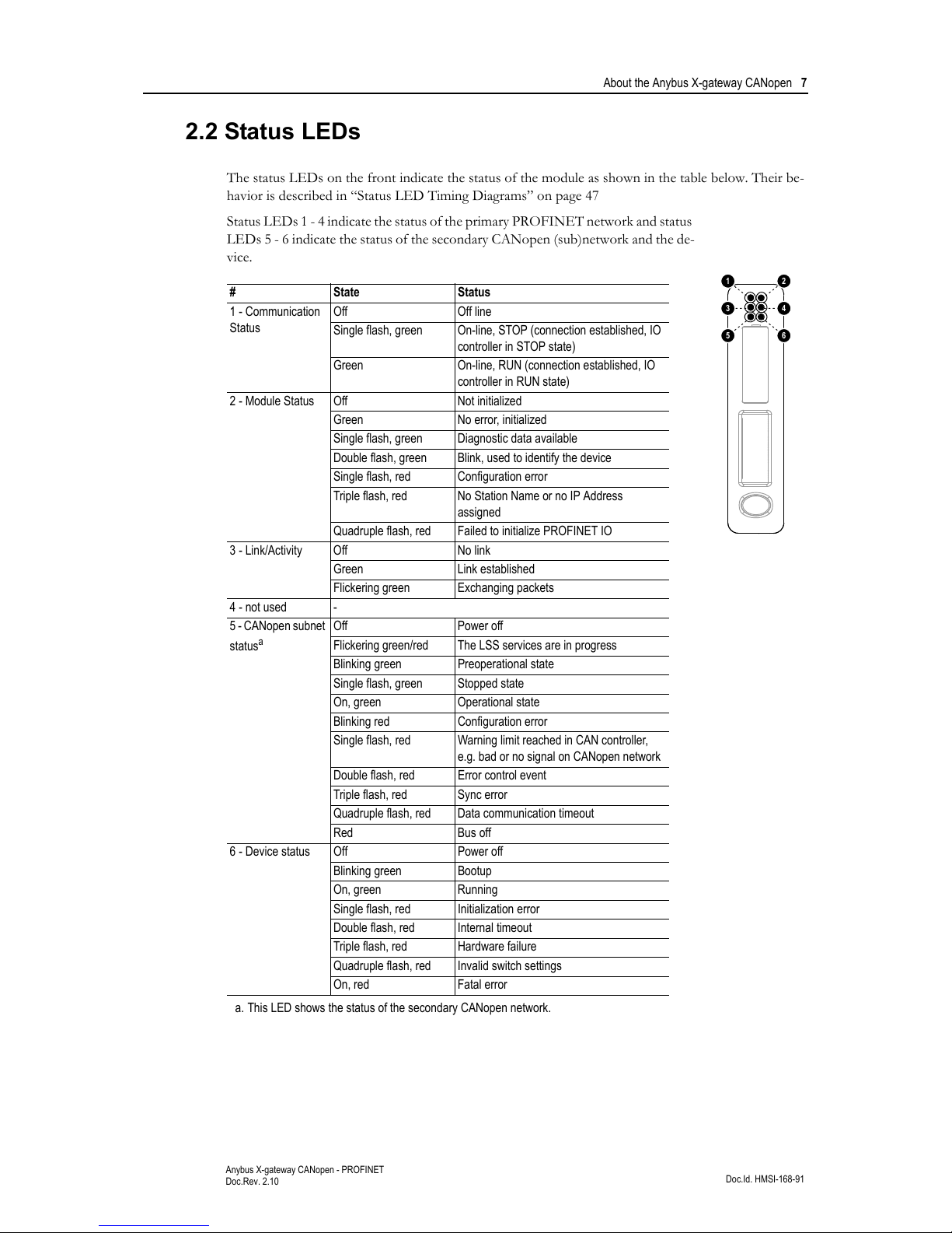
2.2 Status LEDs
The status LEDs on the front indicate the status of the module as shown in the table below. Their be-
havior is described in “Status LED Timing Diagrams” on page 47
Status LEDs 1 - 4 indicate the status of the primary PROFINET network and status
LEDs 5 - 6 indicate the status of the secondary CANopen (sub)network and the de-
vice.
# State Status
1 - Communication
Status
Off Off line
Single flash, green On-line, STOP (connection established, IO
controller in STOP state)
Green On-line, RUN (connection established, IO
controller in RUN state)
2 - Module Status Off Not initialized
Green No error, initialized
Single flash, green Diagnostic data available
Double flash, green Blink, used to identify the device
Single flash, red Configuration error
Triple flash, red No Station Name or no IP Address
assigned
Quadruple flash, red Failed to initialize PROFINET IO
3 - Link/Activity Off No link
Green Link established
Flickering green Exchanging packets
4 - not used -
5 - CANopen subnet
status
a
a. This LED shows the status of the secondary CANopen network.
Off Power off
Flickering green/red The LSS services are in progress
Blinking green Preoperational state
Single flash, green Stopped state
On, green Operational state
Blinking red Configuration error
Single flash, red Warning limit reached in CAN controller,
e.g. bad or no signal on CANopen network
Double flash, red Error control event
Triple flash, red Sync error
Quadruple flash, red Data communication timeout
Red Bus off
6 - Device status Off Power off
Blinking green Bootup
On, green Running
Single flash, red Initialization error
Double flash, red Internal timeout
Triple flash, red Hardware failure
Quadruple flash, red Invalid switch settings
On, red Fatal error
1
3
5
2
4
6
About the Anybus X-gateway CANopen 8
Doc.Id. HMSI-168-91
Anybus X-gateway CANopen - PROFINET
Doc.Rev. 2.10
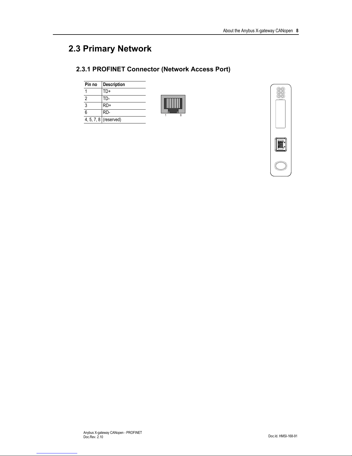
2.3 Primary Network
2.3.1 PROFINET Connector (Network Access Port)
Pin no Description
1TD+
2TD-
3 RD+
6 RD-
4, 5, 7, 8 (reserved)
18
About the Anybus X-gateway CANopen 9
Doc.Id. HMSI-168-91
Anybus X-gateway CANopen - PROFINET
Doc.Rev. 2.10
2.4 Secondary Network
2.4.1 CANopen Connector
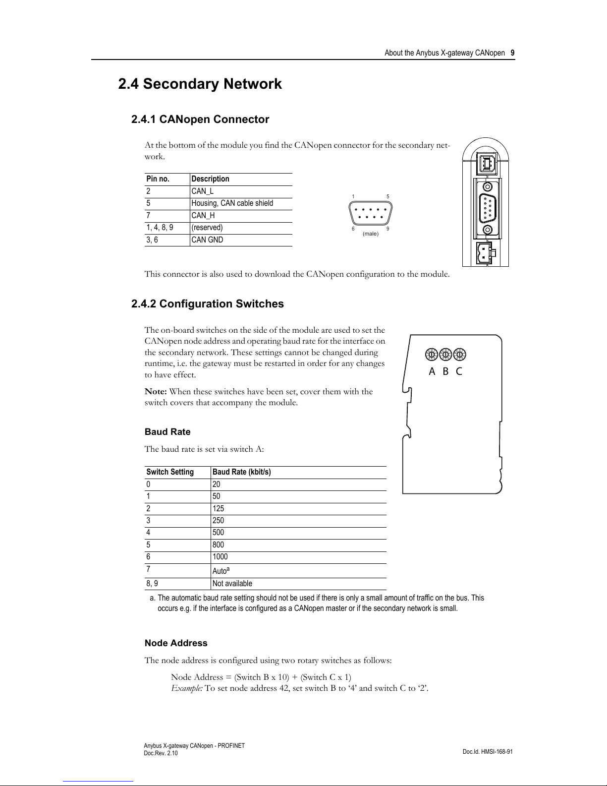
At the bottom of the module you find the CANopen connector for the secondary net-
work.
This connector is also used to download the CANopen configuration to the module.
2.4.2 Configuration Switches
The on-board switches on the side of the module are used to set the
CANopen node address and operating baud rate for the interface on
the secondary network. These settings cannot be changed during
runtime, i.e. the gateway must be restarted in order for any changes
to have effect.
Note: When these switches have been set, cover them with the
switch covers that accompany the module.
Baud Rate
The baud rate is set via switch A:
Node Address
The node address is configured using two rotary switches as follows:
Node Address = (Switch B x 10) + (Switch C x 1)
Example: To set node address 42, set switch B to ‘4’ and switch C to ‘2’.
Pin no. Description
2CAN_L
5 Housing, CAN cable shield
7 CAN_H
1, 4, 8, 9 (reserved)
3, 6 CAN GND
Switch Setting Baud Rate (kbit/s)
020
150
2125
3250
4500
5800
6 1000
7
Auto
a
a. The automatic baud rate setting should not be used if there is only a small amount of traffic on the bus. This
occurs e.g. if the interface is configured as a CANopen master or if the secondary network is small.
8, 9 Not available
15
96
(male)
0
1
2
3
4
5
6
7
8
9
0
1
2
3
4
5
6
7
8
9
0
1
2
3
4
5
6
7
8
9
A B C
About the Anybus X-gateway CANopen 10
Doc.Id. HMSI-168-91
Anybus X-gateway CANopen - PROFINET
Doc.Rev. 2.10
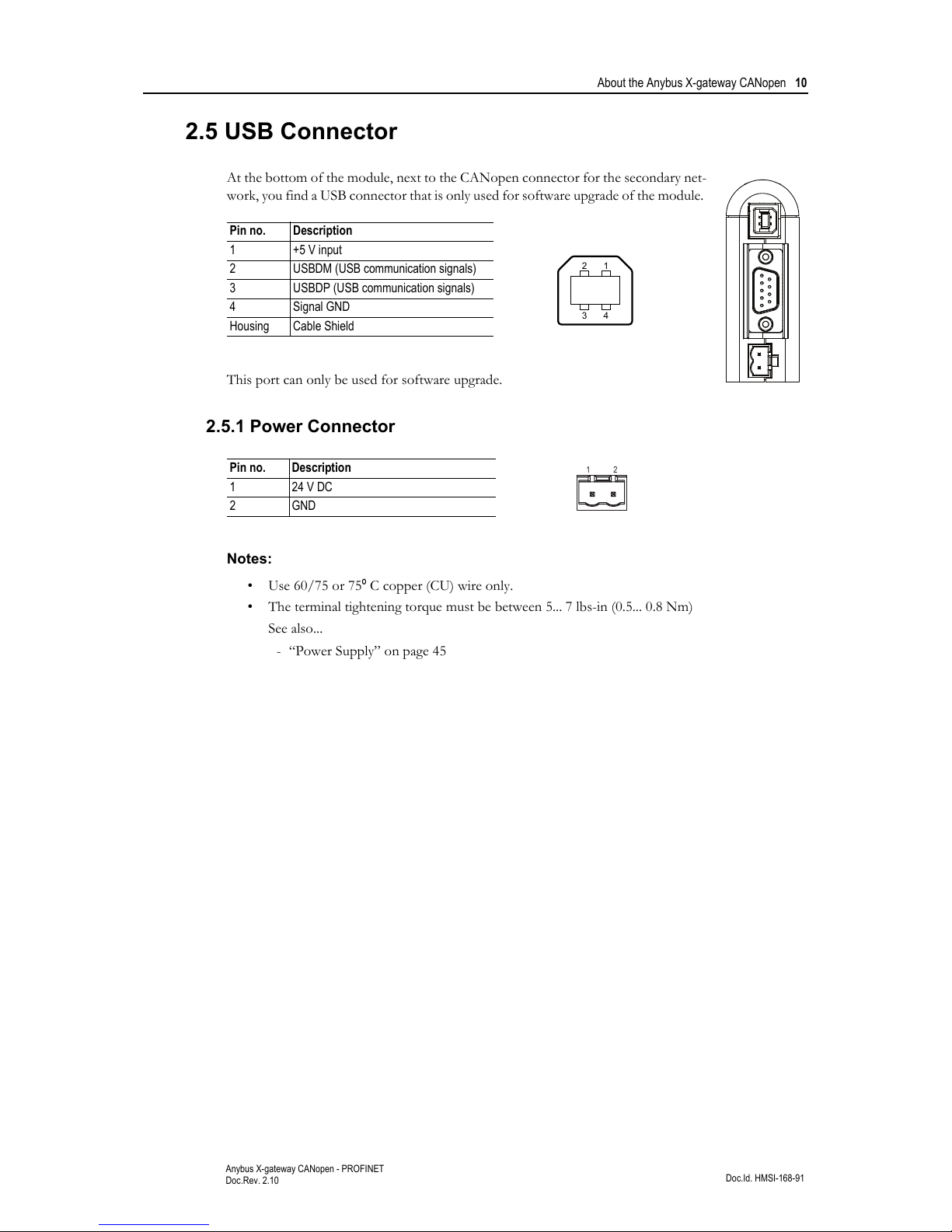
2.5 USB Connector
At the bottom of the module, next to the CANopen connector for the secondary net-
work, you find a USB connector that is only used for software upgrade of the module.
This port can only be used for software upgrade.
2.5.1 Power Connector
Notes:
• Use 60/75 or 75
º C copper (CU) wire only.
• The terminal tightening torque must be between 5... 7 lbs-in (0.5... 0.8 Nm)
See also...
- “Power Supply” on page 45
Pin no. Description
1 +5 V input
2 USBDM (USB communication signals)
3 USBDP (USB communication signals)
4 Signal GND
Housing Cable Shield
Pin no. Description
1 24 V DC
2GND
1
2
3
4
12

About the Anybus X-gateway CANopen 11
Doc.Id. HMSI-168-91
Anybus X-gateway CANopen - PROFINET
Doc.Rev. 2.10
2.6 Hardware Installation
Perform the following steps when mounting the gateway:
1. Set the Node Address and the baud rate for the secondary CANopen network (see “Configura-
tion Switches” on page 9).
2. Snap the gateway on to the DIN-rail (See “External View” on page 6)
The DIN-rail mechanism works as follows:
To snap the gateway on, first press it downwards (1) to compress the
spring in the DIN-rail mechanism, then push it against the DIN-rail as to
make it snap on (2).
To snap the gateway off, push it downwards (1) and pull it out from the
DIN-rail (2), as to make it snap off from the DIN-rail.
3. Connect the gateway to the secondary CANopen network.
4. Connect the gateway to the PROFINET network.
5. Connect the power cable and apply power
1
2
1
2
About the Anybus X-gateway CANopen 12
Doc.Id. HMSI-168-91
Anybus X-gateway CANopen - PROFINET
Doc.Rev. 2.10
2.7 CANopen Electronic Data Sheet (EDS)
Each device on CANopen is associated with a CANopen Electronic Data Sheet (a.k.a EDS file), which
holds a description of the device and its functions. Most importantly, the file describes the object dic-
tionary implementation in the device. This file should be uploaded to the CANopen configuration tool
when configuring the secondary CANopen network.
The latest version of the EDS file for the Anybus X-gateway CANopen can be downloaded from the
HMS web site, ‘www.anybus.com’.
2.8 PROFINET Generic Station Description (GSD file)
Each device in a PROFINET network is associated with a Generic Station Description (a GSD file),
which describes the implementation of the product. This file is used by the network configuration tool
during network configuration.
The latest version of the GSD file for the Anybus X-gateway PROFINET interface, can be downloaded
from the HMS web site, ‘www.anybus.com’ or obtained by contacting HMS.
 Loading...