

HMS Anybus X-gateway CANopen User Manual
AAnnyybbuuss®®XX--ggaatteewwaayy™™CCAANNooppeenn
PPRROOFFIINNEETT®®IIRRTT ((22..3322))
USER MANUAL
SCM-1202-029 1.2 en-US ENGLISH
®®

Important User Information
Disclaimer
The information in this document is for informational purposes only. Please inform HMS Industrial Networks of any
inaccuracies or omissions found in this document. HMS Industrial Networks disclaims any responsibility or liability
for any errors that may appear in this document.
HMS Industrial Networks reserves the right to modify its products in line with its policy of continuous product
development. The information in this document shall therefore not be construed as a commitment on the part of
HMS Industrial Networks and is subject to change without notice. HMS Industrial Networks makes no commitment
to update or keep current the information in this document.
The data, examples and illustrations found in this document are included for illustrative purposes and are only
intended to help improve understanding of the functionality and handling of the product. In view of the wide range
of possible applications of the product, and because of the many variables and requirements associated with any
particular implementation, HMS Industrial Networks cannot assume responsibility or liability for actual use based on
the data, examples or illustrations included in this document nor for any damages incurred during installation of the
product. Those responsible for the use of the product must acquire sufficient knowledge in order to ensure that the
product is used correctly in their specific application and that the application meets all performance and safety
requirements including any applicable laws, regulations, codes and standards. Further, HMS Industrial Networks will
under no circumstances assume liability or responsibility for any problems that may arise as a result from the use of
undocumented features or functional side effects found outside the documented scope of the product. The effects
caused by any direct or indirect use of such aspects of the product are undefined and may include e.g. compatibility
issues and stability issues.
®
Anybus
are the property of their respective holders.
is a registered trademark of HMS Industrial Networks AB. All other trademarks mentioned in this document
Anybus®X-gateway™CANopen®PROFINET®IRT (2.32) User Manual
SCM-1202-029 1.2 en-US

Table of Contents
Page
1 Preface ................................................................................................................................. 3
1.1 About This Document ............................... ....................................... .......................... .......3
1.2 Document history .......................... .......................... ............. .......................... ............. .... 3
1.3 Document Conventions ........... .......................... .......................... ......................................4
1.4 Document-Specific Conventions......... ..... .......................... ....................................... ........... 4
2 Description .......................................................................................................................... 5
2.1 Introduction............................ ..... .......................... ....................................... ..................5
2.2 Data Exchange ................ .................................. ..... .......................... ................................ 6
2.3 CANopen Functionality. ........ .......................... ............. .......................... ............. ...............7
3 Installation........................................................................................................................... 8
3.1 Installation Overview .... .......................... ............. .......................... ................................... 8
3.2 DIN Rail Mounting..... ............. .......................... .......................... ............. .........................9
3.3 Power Connector ..................... ............. .......................... ....................................... ..........9
3.4 USB Connector ............ .......................... ............. .......................... ................................... 9
3.5 Secondary CANopen Network Interface .................................................. .......................... . 10
3.6 PROFINET IRT Network Interface...... ............. ............. .......................... ............. ................ 11
3.7 LED Indicators ............. .......................... ....................................... ............................... .. 12
4 Configuration..................................................................................................................... 14
4.1 Configuration Overview. .......................... ............. .......................... ................................. 14
4.2 Configuring the Secondary CANopen Network................................... .......................... ........ 15
4.3 Configuring the PROFINET IRT (2.32) Interface......................... .......................... ..... ............. 16
4.4 Enabling Data Exchange ........................................ ............................... ........................... 22
5 PROFINET Asset Management.......................................................................................... 23
5.1 Asset Management Record ................................ .......................... ..... ............................... 23
5.2 Recording and Reading Data ............... .......................... ............. .......................... ............ 23
5.3 Supported File Formats ...... ............. .......................... ....................................... ............... 24
5.4 Supported Asset Management Records....................... .......................... ............. ................ 24
5.5 XML Based Asset Management.. ............. ............. ............. .......................... ...................... 25
5.6 Binary Based Asset Management ........................ ............. ............. ............. ....................... 28
5.7 Uploading the Asset Management File to the FTP Server.... ............................... .................... 32
Anybus®X-gateway™CANopen®PROFINET®IRT (2.32) User Manual
SCM-1202-029 1.2 en-US

6 CANopen Module Specification........................................................................................ 34
6.1 NMT State Machine.............. ............. .......................... ................................................... 34
6.2 CANopen Data Exchange .. .......................... ............. .......................... .......................... .... 35
6.3 LSS Services ..................................... .......................... ............. .......................... ............ 39
6.4 Error Control .... ....................................... .......................... ............. .......................... ..... 40
6.5 CANopen Emergency Messages ......... ..... .................................. ............................... ......... 41
6.6 CANopen Live List Functionality ................ ............. .......................... ............. .................... 42
7 CANopen Object Implementation .................................................................................... 44
7.1 Static Data Types .............. ..... ....................................... .......................... ....................... 44
7.2 Communication Profile Area ......... ....................................... .......................... ..... ............. 44
7.3 Manufacturer Specific Objects......................... ................................................................. 52
A Technical Data ................................................................................................................... 59
A.1 General Specifications............... ..... .................................. ............................... ................ 59
A.2 Secondary CANopen Network Interface .................................................. .......................... . 59
A.3 Primary PROFINET IRT (2.32) Network Interface ................................ .......................... ........ 59
Anybus®X-gateway™CANopen®PROFINET®IRT (2.32) User Manual
SCM-1202-029 1.2 en-US

Preface 3 (60)
1 Preface
1.1 About This Document
This document describes Anybus X-gateway CANopen PROFINET IRT (2.32).
For additional related documentation and file downloads, please visit www.anybus.com/support.
1.2 Document history
Version
1.0 2017-01-23
1.1 2017-11-22
1.2 2019-04-11
Date
Description
First release
Updated for new firmware
Added section about PROFINET Asset Management
®
Anybus
X-gateway™CANopen®PROFINET®IRT (2.32) User Manual
SCM-1202-029 1.2 en-US
Preface 4 (60)
1.3 Document Conventions
Ordered lists are used for instructions that must be carried out in sequence:
1. First do this
2. Then do this
Unordered (bulleted) lists are used for:
• Itemized information
• Instructions that can be carried out in any order
...and for action-result type instructions:
► This action...
→ leads to this result
Bold typeface indicates interactive parts such as connectors and switches on the hardware, or
menus and buttons in a graphical user interface.
Monospaced text is used to indicate program code and other
kinds of data input/output such as configuration scripts.
This is a cross-reference within this document: Document Conventions, p. 4
This is an external link (URL): www.hms-networks.com
This is additional information which may facilitate installation and/or operation.
This instruction must be followed to avoid a risk of reduced functionality and/or damage
to the equipment, or to avoid a network security risk.
Caution
This instruction must be followed to avoid a risk of personal injury.
WARNING
This instruction must be followed to avoid a risk of death or serious injury.
1.4 Document-Specific Conventions
• Hexadecimal values are represented with the suffix h and a leading zero where needed, e.g.
the hexadecimal value 1F4 is written 01F4h.
• A byte always consists of 8 bits.
Anybus®X-gateway™CANopen®PROFINET®IRT (2.32) User Manual
SCM-1202-029 1.2 en-US

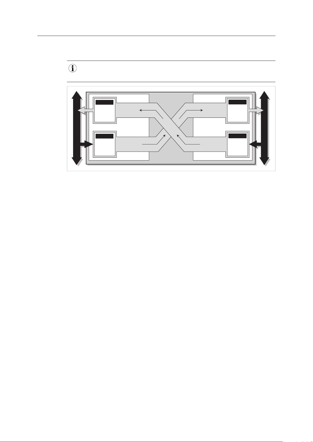
Description
Secondary CANopen network
Primary fieldbus or Ethernet network
SlaveMaster Slave Slave Slave
SlaveSlave Slave Slave Slave
Secondary CANopen network interface
(master or slave)
Primary network interface
2 Description
2.1 Introduction
Anybus X-gateway CANopen is designed to provide a seamless connection between a primary
fieldbus or Ethernet network and a secondary CANopen sub-network.
The X-gateway transmits I/O data transparently between the two networks. Data from the
primary network is written into CANopen objects that can be mapped into CANopen PDOs or
read via CANopen SDOs, and vice versa. This makes it possible to integrate CANopen devices into
almost any other PLC system and their supported networks.
No proprietary configuration software is needed for Anybus X-gateway CANopen, although
dedicated tools may be required when configuring the primary network. Any standard CANopen
configuration tool can be used to configure the secondary CANopen network interface.
5 (60)
Fig. 1 Networking example
Anybus®X-gateway™CANopen®PROFINET®IRT (2.32) User Manual
SCM-1202-029 1.2 en-US
Description
Primary Network InterfaceSecondary Network Interface
Primary Network
Secondary CANopen Network
Data From
Primary
Network
Data From
Secondary
Network
Data To
Primary
Network
Data To
Secondary
Network
Status Word
Status Word
Control Word
Control Word
2.2 Data Exchange
The terminology and definitions used for different types of data vary between network types. All data
transported through the Anybus X-gateway CANopen are fast, cyclic data, and will in this document
simply be referred to as “I/O data”.
Fig. 2 Data exchange example
6 (60)
Each of the two network interfaces exchanges data on its network through its own buffer, which
can hold up to 512 bytes of data. The first two bytes in the primary network buffer are reserved
for the Control Word and Status Word, leaving 510 bytes available for I/O data.
The actual amount of data that can be exchanged depend on the application and network used
and may therefore be less than 510 bytes, which is only the maximum size of the buffer.
The Control Word can be used by the master on the primary network to start and stop the
exchange of data, and to reset the X-gateway if needed. The Status Word can be used by the
master to read the status of the secondary CANopen network.
The I/O data exchange is separated from the network data exchange. While the gateway ensures
data consistency (where applicable), it does not feature any mechanisms for synchronisation
between the primary and secondary networks.
Anybus®X-gateway™CANopen®PROFINET®IRT (2.32) User Manual
SCM-1202-029 1.2 en-US

Description
2.3 CANopen Functionality
The functionality of the secondary CANopen network interface is defined by the following
CANopen specifications:
• KGB Draft Standard 301 version 4.2.0 (Rev. 4.2)
• CiA Draft Standard Proposal 302 Part 1–5.
Supported CANopen Services
Communication and parameters in the CANopen protocol are built around åbject. Different
services are used for communication with the objects and for other tasks such as supervising the
network. Which services are available depend on whether the secondary CANopen network
interface is operating as a master or as a slave.
The secondary CANopen network will start up as a slave by default.
7 (60)
Service
NMT (Network Management)
CMT (Configuration Management)
PDO (Process Data Objects)
SDO (Service Data Objects)
SYNC (Synchronization Object)
EMCY (Emergency Object)
LSS (Layer Setting Services)
Heartbeat Mechanism
Node Guarding Protocol
Available in
Master
Master
Master/Slave Used for I/O communication.
Master/Slave
Master/Slave
Master/Slave
Master
Master/Slave
Master/Slave
Description
NMT messages are used to configure, initialize and
monitor the network,and for error handling.
CMT messages are used for configuring CANopen devices.
This primarily involves PDO parameters and mapping of
information.
128 Receive PDOs and 128 Transmit PDOs are
implemented, each being able to transfer up to 8 bytes.
The total number of PDOs that can be used is limited by
the data buffer size.
Supported PDO message types are COS (Change of state),
Cyclic Synchronous, and Acyclic Synchronous.
Used to access and configure objects in the X-gateway and
other network nodes without mapping them to an I/O
(PDO) connection.
SDOs use asynchronous data transmission and can transfer
more than 8 bytes (the limit for a PDO).
Supported SDO message types are Expedited Upload/
Download Protocol and Segmented Upload/Download
Protocol.
Used for synchronizing PDO communication. A master can
be either a producer or a consumer of the synchronization.
A slave can only be a consumer.
Used for error reporting when a fatal error has occurred in
the X-gateway or in other monitored or supervised
modules.
Used by a CANopen master to configure the baud rate and
NodeID of slaves that support LSS.
Allows a device to monitor the status of another node. The
X-gateway can appear both as heartbeat producer and
consumer.
Provides active surveillance of a slave by the master.
Slaves can be configured to expect a node guarding
request from the master.
®
Anybus
X-gateway™CANopen®PROFINET®IRT (2.32) User Manual
SCM-1202-029 1.2 en-US
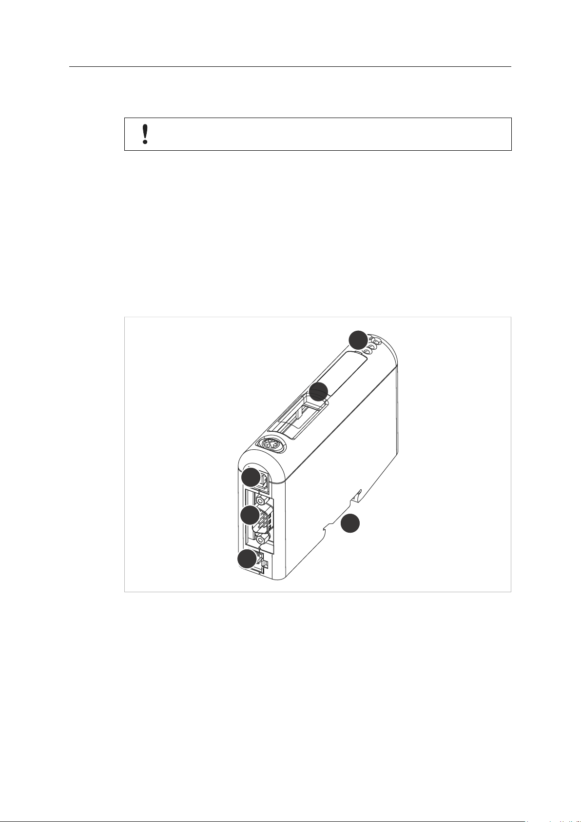
Installation 8 (60)
A
B
C
D
E
F
3 Installation
This product contains parts that can be damaged by electrostatic discharge (ESD). Use
ESD prevention measures to avoid damage.
3.1 Installation Overview
Basic steps when installing the Anybus X-gateway CANopen:
1. Set the node address and baud rate for the secondary CANopen interface.
2. Set the hardware configuration switches for the primary network interface (if applicable).
3. Mount the gateway on the DIN rail.
4. Connect the primary and secondary networks.
5. Connect the power cable and apply power.
6. Continue to Configuration, p. 14.
Fig. 3 Connectors, switches and indicators
A
B
C USB connector
D CANopen connector
E Power connector
F
LED indicators
Primary network interface
DIN rail mount
Anybus®X-gateway™CANopen®PROFINET®IRT (2.32) User Manual
SCM-1202-029 1.2 en-US
Installation 9 (60)
1 2
1
2
3
4
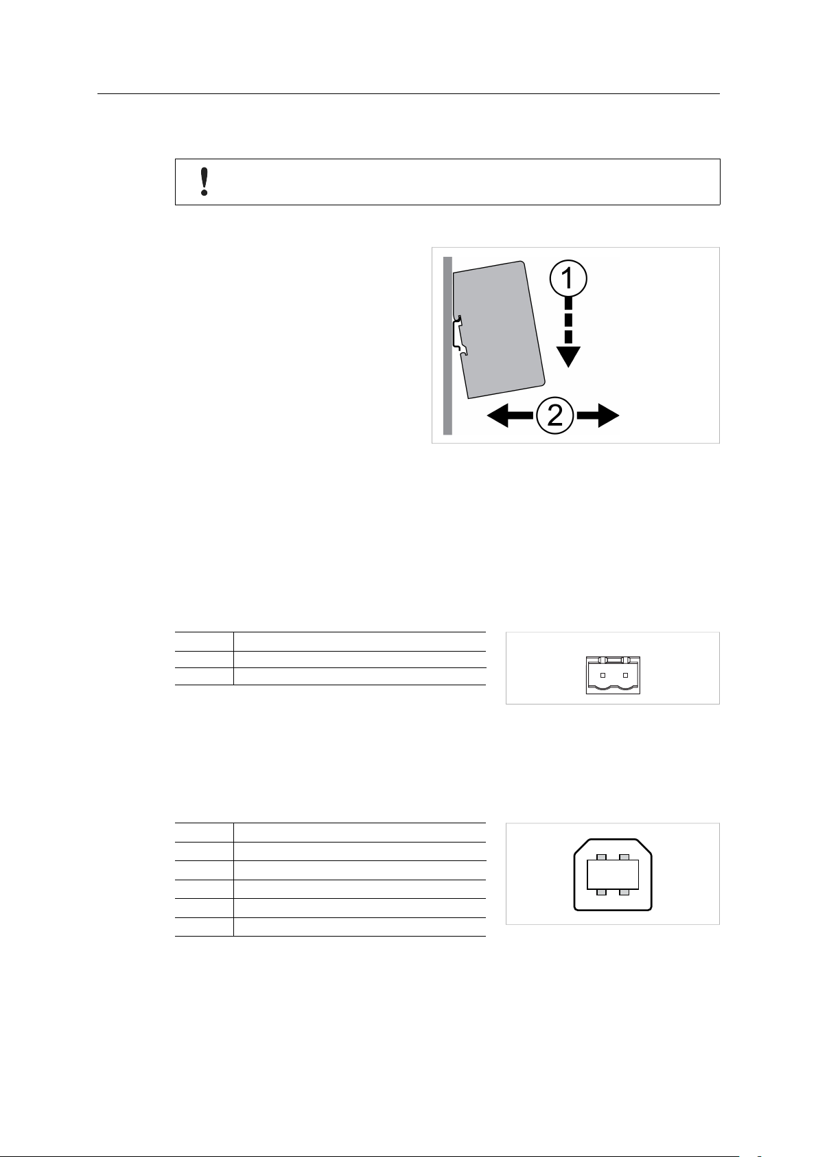
3.2 DIN Rail Mounting
The unit must be electrically grounded through the DIN rail for EMC compliance.
Mount on DIN rail
1. Hook the unit onto the upper lip of
the rail and push gently downwards.
2. Push the unit towards the rail until it
snaps into place.
Fig. 4 Push down to mount or remove
Remove from DIN rail
1. Push the unit gently downwards on the rail.
2. Pull the bottom end of the unit free of the rail and remove it.
3.3 Power Connector
See also Technical Data, p. 59 regarding power supply requirements.
Pin Signal
1 +24 VDC
2
Power Ground
3.4 USB Connector
The USB connector is only used when upgrading the firmware of the unit. It cannot be used for
configuration purposes.
Pin
1 +5 V input
2
3
4
Housing
Signal
USBDM (USB communication)
USBDP (USB communication)
Signal ground
Cable shield
Fig. 5 Power connector
Fig. 6 USB type B connector
®
Anybus
X-gateway™CANopen®PROFINET®IRT (2.32) User Manual
SCM-1202-029 1.2 en-US
Installation 10 (60)
0
1
2
3
4
5
6
7
8
9
0
1
2
3
4
5
6
7
8
9
0
1
2
3
4
5
6
7
8
9
ABC
x1
x1 0
+= 42
BC
69
5 1(male)
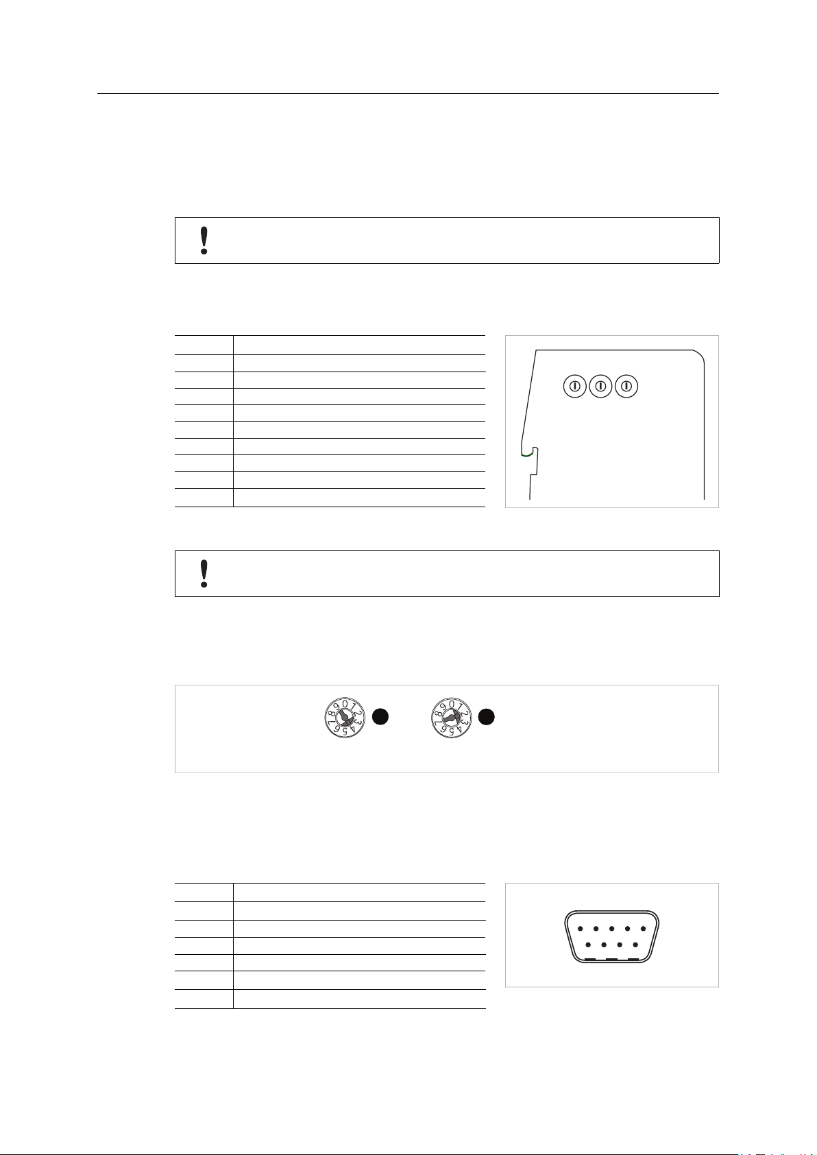
3.5 Secondary CANopen Network Interface
3.5.1 Configuration Switches
Three configuration switches on the side of the unit are used to set the node address and baud
rate for the secondary CANopen network interface.
The node address and baud rate cannot be changed during runtime. The module must be
restarted to make a changed setting take effect.
Baud Rate (Switch A)
The first rotary switch is used to set the operating baud rate.
Setting
Baud Rate (kbit/s)
0 20
1 50
2 125
3 250
4 500
5 800
6 100
7 Auto
8, 9
(not used)
Fig. 7 Configuration switches
Do not select “Auto” if the traffic on the secondary network will be limited, e.g. if there
are only a few nodes or the interface is configured as a master.
Node Adress (Switches B + C)
The second and third switches are used together to set a CANopen node address between 1 and
99. In the following example the node address is set to 42 (4 x 10 + 2 x 1):
Fig. 8 Node address example
3.5.2 CANopen Connector
The secondary network CANopen connector is located on the bottom of the unit. This connector
is also used when downloading the CANopen configuration.
Pin
2 CAN_L
3 CAN GND
5
6 CAN GND
7 CAN_H
1, 4, 8, 9
Anybus®X-gateway™CANopen®PROFINET®IRT (2.32) User Manual
Signal
Shield
(reserved)
Fig. 9 CANopen connector
SCM-1202-029 1.2 en-US
Installation 11 (60)
1 8
LAN 1 LAN 2
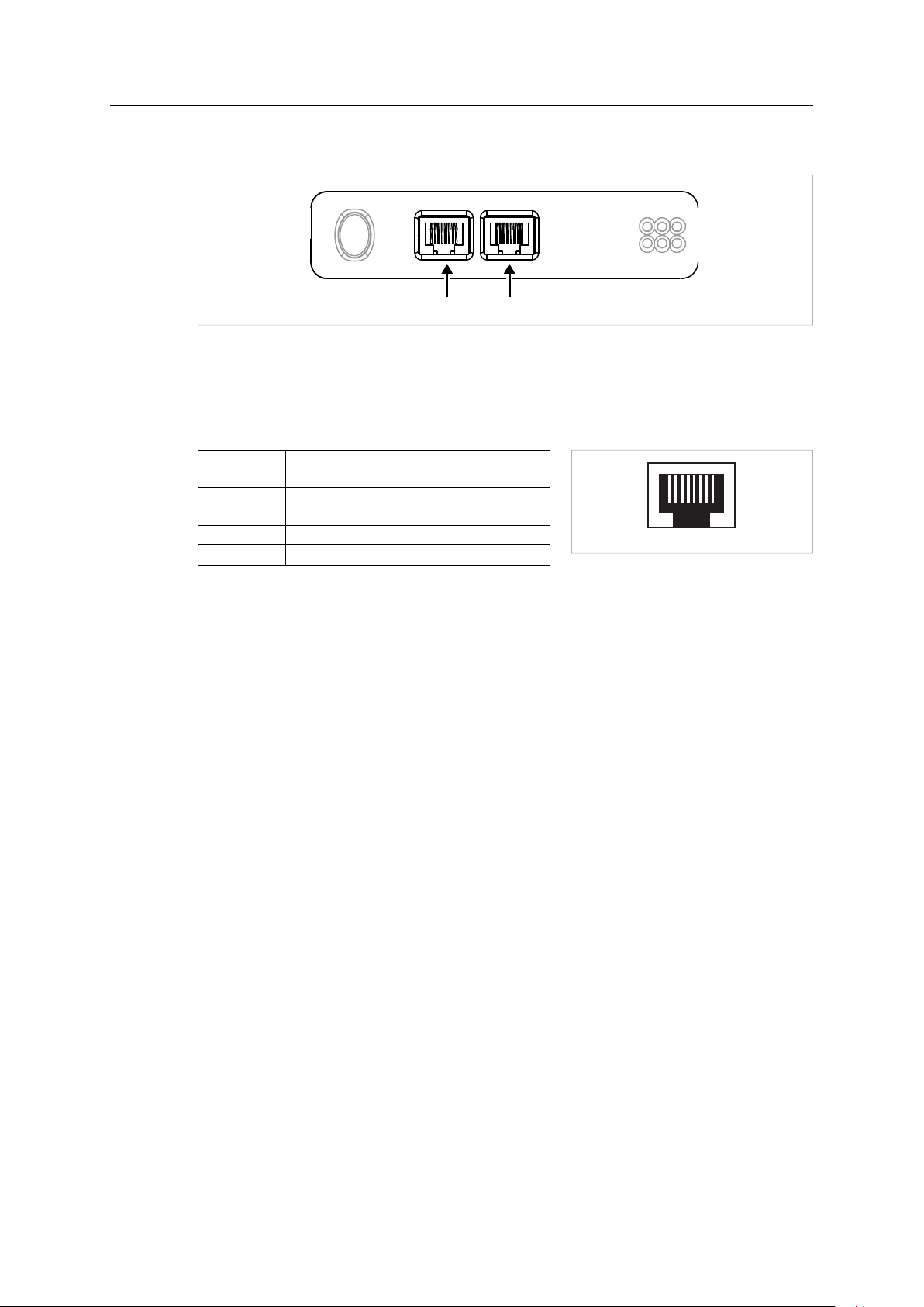
3.6 PROFINET IRT Network Interface
Fig. 10 PROFINET IRT interface
Ethernet Connectors (LAN 1/LAN 2)
The PROFINET IRT interface contains a dual port Ethernet switch with RJ45 type connectors. The
two ports are labeled LAN 1 and LAN 2.
Pin Function
1 TD+
2 TD-
3 RD+
6 RD-
4, 5, 7, 8
(reserved)
Fig. 11 Ethernet connector (RJ45)
Anybus®X-gateway™CANopen®PROFINET®IRT (2.32) User Manual
SCM-1202-029 1.2 en-US

Installation 12 (60)
1 2
3
546
3.7 LED Indicators
LED 1 to 4
LED 5
LED 6 Device operation status
Primary network interface status
Secondary CANopen network interface status
LED Indicators – Primary PROFINET IRT Network Interface
1 - Network Status Off Offline
Green
Green, 1 flash Online (STOP)
Red Fatal error
Red, 1 flash
Red, 2 flashes IP address error
Red, 3 flashes Configuration error
Alternating red/green
2 - Module Status Off No power or initializing
Green
Green, 1 flash
Red Fatal error
Alternating red/green
3 - Link/Activity 1
4 - Link/Activity 2
Off No power or no link detected
Green
Green, flickering
– No power
– No connection to IO Controller
Online (RUN)
– Connection to IO Controller
– Connection to IO Controller
– IO Controller in STOP state or IO data bad
– RT synchronization not finished
Station name error
Firmware update in progress
Normal operation
Diagnostic event present
Firmware update in progress
Link OK
Transmitting/receiving data
LED Indicators – Secondary CANopen Network Interface & Device Status
5 - CANopen Status
6 - Device Status
Off
Flickering red/green
Green
Green, 1 flash Stopped state
Green, blinking Pre-operational state
Red Bus off
Red, 1 flash Warning limit reached
Red, 2 flashes Error control event
Red, 3 flashes
Red, 4 flashes
Red, blinking Configuration error
Off Power off
Green Running
Green, 1 flash
Red Fatal error
Red, 1 flash Initialization error
Red, 2 flashes
Red, 3 flashes Hardware failure
Red, 4 flashes Invalid switch settings
No power
LSS services in progress
Operational state
Sync error
Data communication timeout
Bootup
Timeout error
®
Anybus
X-gateway™CANopen®PROFINET®IRT (2.32) User Manual
SCM-1202-029 1.2 en-US
Installation 13 (60)
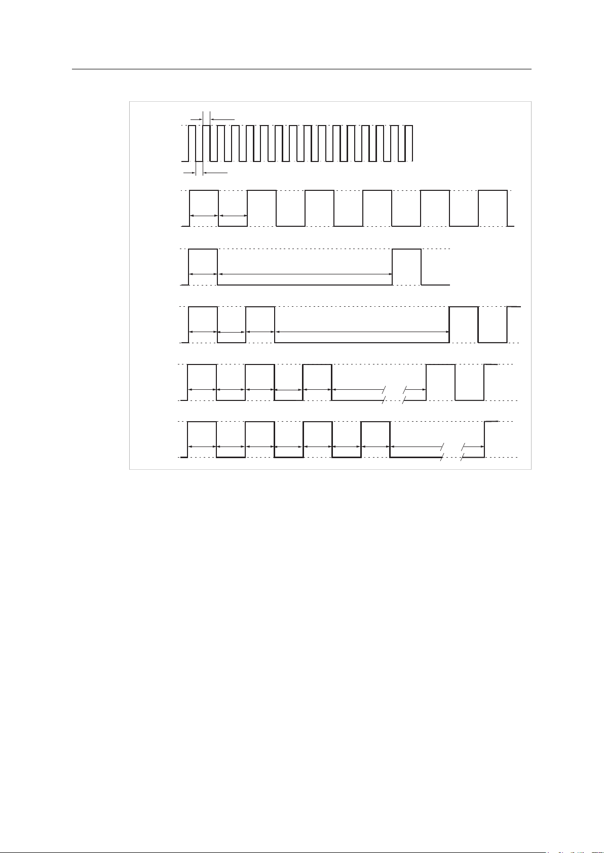
On
Off
50 ms
50 ms
Flickering
LED
On
Off
Blinking
LED
200 ms
200 ms
On
Off
Single flash
LED
200 ms
1000 ms
On
Off
Double flash
LED
200 ms
1000 ms
200 ms
200 ms
On
Off
Quadruple flash
LED
200 ms
1000 ms
200 ms
200 ms
200 ms 200 ms 200 ms 200 ms
On
Off
Triple flash
LED
200 ms
1000 ms
200 ms
200 ms
200 ms 200 ms
LED Indicator Timing Intervals
Fig. 12 LED indicator timing intervals
®
Anybus
X-gateway™CANopen®PROFINET®IRT (2.32) User Manual
SCM-1202-029 1.2 en-US

Configuration 14 (60)
4 Configuration
4.1 Configuration Overview
Device Description Files
A device description file contains a description of a network device, its functions, object
dictionary implementations, etc., and is used when configuring the network interface. The device
description file can be referred to as an EDS, GSD, DDF, etc., depending on the type of network.
The latest versions of the device description files to use with Anybus X-gateway CANopen can be
downloaded from www.anybus.com/support.
Basic steps when configuring Anybus X-gateway CANopen
The secondary network interface should be configured first. The gateway must then be
power cycled before configuring the primary network interface.
1. Determine the amount of data that should be transferred. This value will be entered in the
secondary CANopen network interface configuration.
2. Configure the secondary CANopen network interface.
See Configuring the Secondary CANopen Network, p. 15.
3. Power cycle the X-gateway.
4. Configure the primary network interface.
See Configuring the PROFINET IRT (2.32) Interface, p. 16.
Module Identification
Anybus X-gateway CANopen will identify itself on the network as follows:
Description Value
Vendor Code
Vendor Name “HMS Networks”
Product Code
Product Type
Product Type String “Communications Adapter”
Product Name “Anybus X-gateway CANopen”
Catalog “Anybus X-gateway CANopen”
Desc Text
90
51
12
“Anybus X-gateway CANopen”
®
Anybus
X-gateway™CANopen®PROFINET®IRT (2.32) User Manual
SCM-1202-029 1.2 en-US

Configuration 15 (60)
4.2 Configuring the Secondary CANopen Network
This is a generic description of the basic steps in configuring the secondary CANopen network
interface using an external CANopen configuration tool. For instructions on how to create and
apply a configuration, please refer to the documentation for the configuration tool used.
1. Download the Anybus X-gateway CANopen EDS file from www.anybus.com/support.
2. Prepare EDS files for the other nodes on the secondary CANopen network.
3. Open the CANopen configuration tool and upload the EDS files to it.
4. Configure the following parameters in the Anybus X-gateway CANopen:
Parameter
NodeID
Baud Rate
Master/Slave
Input Data Size
(object 3000h)
Output Data Size
(object 3001h)
Value range
1 to 127
20, 50, 125, 250, 500,
800, 1000, Auto
Master or Slave Default = Slave. See also NMT Start-up, 1F80h, p. 48.
2 to 512
2 to 512
Comment
NodeID 1 to 99 can be set with the configuration switches.
NodeID 99 to 127 can only be be set using a configuration tool or
from the CANopen network.
Set with configuration switch.
Auto should only be used when configured as a slave.
Size of the data transmitted to the primary network.
Bytes 0 and 1 are reserved for the Status Word, leaving a
maximum of 510 bytes available for data. The actual maximum
data size depends on the primary network.
Default = 16 bytes (14 bytes data + 2 bytes Status Word).
Size of the data received from the primary network.
Bytes 0 and 1 are reserved for the Control Word, leaving a
maximum of 510 bytes available for data. The actual maximum
data size depends on the primary network.
Default = 16 bytes (14 bytes data + 2 bytes Control Word).
5. Configure the other CANopen nodes as needed. Make sure that each node uses the same
baud rate and has a unique NodeID.
6. Download the configuration from the tool to each CANopen node.
The configuration can be downloaded individually to each node, or as a Concise DCF file to
the CANopen master which will then configure the slaves.
7. Power cycle the X-gateway.
8. Continue to Configuring the PROFINET IRT (2.32) Interface, p. 16.
The secondary CANopen network will start up as a slave by default.
Anybus®X-gateway™CANopen®PROFINET®IRT (2.32) User Manual
SCM-1202-029 1.2 en-US

Configuration 16 (60)
4.3 Configuring the PROFINET IRT (2.32) Interface
The secondary network interface should always be configured first. The gateway must
then be power cycled before configuring the primary network interface.
The primary network interface of the X-gateway must be configured with the configuration tool
used for the network it is connected to. The choice of configuration tool depends on the type of
network, the application, and the master used on the primary network.
Application notes describing how to configure primary network interfaces in Anybus X-gateway
CANopen with some of the most common tools can be found at www.anybus.com/support.
4.3.1 PROFINET Data Exchange
PROFINET is the open Industrial Ethernet standard for automation from PROFIBUS and PROFINET
International. The PROFINET IRT device provides PROFINET IO Isochronous Real Time
Communication.
PROFINET makes a clear distinction between fast cyclical data, IO Data, and acyclical data,
Record Data. PROFINET IO Data corresponds to what is generally referred to as I/O Data in
Anybus X-gateway CANopen. PROFINET Record Data is not supported.
PROFINET IO Data (I/O Data)
PROFINET IO Data is exchanged cyclically and is built up by I/O modules. The actual I/O
configuration is determined by the PROFINET IO Controller. The modules are mapped to the
Input and Output Buffers in the order of their slot number.
The first two bytes of the I/O data area are reserved for the Control Word and the Status Word,
which are used by the IO Controller to control and report status on the nodes on the secondary
CANopen network. The remainder is available for real-time data transfer using PDOs.
The amount of data exchanged as I/O data is specified when configuring the CANopen master
interface. The data arriving from the CANopen master is completely transparent. The
interpretation must be defined by the master on the primary network.
GSD File
All PROFINET devices are associated with an XML-based GSD file. This file contains information
about the basic capabilities and configuration options of the device.
The latest version of the GSD file for Anybus X-gateway CANopen can be downloaded from
www.anybus.com/support.
Anybus®X-gateway™CANopen®PROFINET®IRT (2.32) User Manual
SCM-1202-029 1.2 en-US

Configuration 17 (60)
4.3.2 Network Configuration
To be able to communicate over Ethernet the network interface needs a valid TCP/IP
configuration. This section explains some basic concepts and describes how to configure the
TCP/IP settings in Anybus X-gateway CANopen using the IPconfig software tool.
When Ethernet communication has been established the TCP/IP settings can also be changed
from the web interface. See Web Pages, p. 21.
Basic TCP/IP Concepts
IP Address
The IP address is used to identify each node on a TCP/IP network. IP addresses are written as
four decimal integers (0–255) separated by dots, where each integer represents the binary value
of one byte of the IP address. This is known as dot-decimal notation.
Example: 10000000 00001010 00000010 00011110 is written as 128.10.2.30
The following IP addresses are reserved for special purposes and cannot be used:
0.n.n.n
127.n.n.n
n.n.n.0
n.n.n.255
First byte zero — used for broadcast messages
First byte 127 — used for loopback addresses to the local host
Last byte zero — identifies a whole network/subnet
Last byte 255 — used for broadcast messages
Subnet Mask
The IP address is divided into three parts: Net ID, Subnet ID and Host ID. A subnet mask is a 32bit binary pattern, where a set bit allocates a bit for Network/Subnet ID, and a cleared bit
allocates a bit for the Host ID. The subnet mask is usually written in dot-decimal notation.
Example: To make the IP address 128.10.2.30 belong to subnet 128.10.2, the subnet
mask must be 255.255.255.0.
Default Gateway
For devices to be able to communicate over Ethernet they must either belong to the same
subnet or communicate via a gateway or router.
A gateway or router routes communication between networks, i.e. it enables the nodes on one
network to access the nodes on another. The default gateway address in the TCP/IP settings of
your product specifies the IP address of the gateway or router on the local network.
Anybus®X-gateway™CANopen®PROFINET®IRT (2.32) User Manual
SCM-1202-029 1.2 en-US
 Loading...