

HMS AnyBus-X Ethernet to DeviceNet Gateway User Manual

AnyBus-X
Ethernet to DeviceNet Gateway
User Manual
Part No. AB7607
Rev 1.11
HMS Industrial Networks
Pilefeltsgatan 93-95
SE-302 50 Halmstad
Sweden
Phone +46 (0) 35 17 29 00
Web www.anybus.com
AB7607 User manual

Table of Contents i
Table of Contents
Preface......................................................................... iv
How to Use This Manual ....................................... iv
Important User Information ................................... iv
Related Documentation........................................... v
Anybus-X Module Description ............................... 1-1
Overview..................................................................... 1-1
Theory of Operation.................................................... 1-2
DeviceNet Features.................................................... 1-3
Ethernet Features....................................................... 1-3
IT-Features ................................................................. 1-4
System Requirements ................................................ 1-4
Hardware Description ................................................. 1-6
Installation................................................................ 2-1
Installation and Operation Requirements ................... 2-1
Power and Network Connections ............................... 2-2
Connecting Power ...................................................... 2-3
Connecting DeviceNet................................................ 2-4
Connecting to Ethernet............................................... 2-4
Configuration ........................................................... 3-1
Anybus-X Configuration Tool (BWConfig) .................. 3-1
Ethernet Network Configuration ................................. 3-6
DeviceNet Network Configuration ............................ 3-14
DeviceNet I/O Configuration..................................... 3-16
Quick Start ............................................................... 4-1
DeviceNet Network Configuration .............................. 4-1
DeviceNet I/O Configuration....................................... 4-9
Ethernet Network Configuration ............................... 4-12
© 2005 HMS Industrial Networks
Using the Ethernet File System ................................ 4-14
DeviceNet Interface.................................................. 5-1
Network Communications........................................... 5-1
Configuration .............................................................. 5-1
AB7607 User manual

Table of Contents ii
Automatic Baud Rate Detection ................................. 5-1
Slave Device Communication..................................... 5-2
Scan Cycles................................................................ 5-2
I/O Message Types .................................................... 5-3
I/O Mapping ................................................................ 5-3
I/O Table Byte Swapping............................................ 5-3
Proxy for Group 2 Only Devices ................................. 5-3
Run/Idle Mode ............................................................ 5-4
Automatic Device Recovery (ADR) ............................ 5-5
Interaction with I/O Tables.......................................... 5-6
EtherNet/IP Interface .............................................. 6-1
Product Features ........................................................ 6-1
CIP Objects ................................................................ 6-1
CIP Messaging ........................................................... 6-2
Assembly Objects and Connections........................... 6-4
Notes About Using ControlLogix I/O Connections...... 6-9
CIP Bridging ............................................................. 6-10
Modbus/TCP Interface............................................ 7-1
Supported Commands................................................ 7-1
Supported Exception Codes....................................... 7-2
Modbus/TCP Addressing............................................ 7-3
I/O Data Content......................................................... 7-4
I/O Data Format.......................................................... 7-7
File System................................................................ 8-1
File System Conventions............................................ 8-1
Security....................................................................... 8-2
Structure ..................................................................... 8-4
Default Files................................................................ 8-5
Virtual File System...................................................... 8-6
System Files ............................................................... 8-6
© 2005 HMS Industrial Networks
Configuration Files...................................................... 8-7
Password Files ......................................................... 8-11
Other Files ................................................................ 8-13
Anybus-X Web Page Files........................................ 8-17
AB7607 User manual

Table of Contents iii
IT Functionality ....................................................... 9-1
Default User Accounts................................................ 9-1
The FTP Server .......................................................... 9-2
The Telnet Server....................................................... 9-2
HTTP Server............................................................... 9-8
SSI Functionality......................................................... 9-9
Email Client .............................................................. 9-23
Displaying I/O Data on a Web Page......................... 9-24
Status and Diagnostics........................................... 10-1
Anybus-X LEDs ........................................................ 10-1
Diagnostic Web Pages ............................................. 10-4
Status Assembly....................................................... 10-7
Specifications.......................................................... 11-1
Environmental Specifications ................................... 11-1
EMC Directive Compliance....................................... 11-1
Electrical Specifications............................................ 11-1
Mechanical Specifications ........................................ 11-2
I/O Data Sizes .......................................................... 11-2
Connectors.............................................................. 12-1
Power ....................................................................... 12-1
DeviceNet ................................................................. 12-2
Ethernet RJ45........................................................... 12-3
Auxiliary RS-232 9 Pin D-Subminiature.................... 12-4
Warranty ................................................................ 13-1
Support ................................................................... 14-1
Technical Product Assistance .................................. 14-1
Contact Information .................................................. 14-1
© 2005 HMS Industrial Networks
AB7607 User manual

How to Use This Manual
This manual provides an overview of the Anybus-X Ethernet to DeviceNet Gate-
way. It describes how to configure and operate it.
Important User Information
The data and illustrations found in this document are not binding. We reserve the
right to modify our products in line with our policy of product development. The
information in this document is subject to change and should not be considered as
Preface iv
Preface
a commitment by HMS Industrial Networks. HMS Industrial Networks assumes
no responsibility for errors that may appear in this document
There are many applications of the Anybus-X module. Those responsible for the
use of this device must satisfy themselves that all necessary steps have been taken
to verify an application meets all performance and safety requirements including
any applicable laws, regulations, codes, and standards.
The illustrations and samples in this guide are intended solely for the purpose of
example. HMS Industrial Networks does not assume responsibility or liability for
actual use based upon the examples shown in this publication.
DeviceNet is a trademark of Open DeviceVendor Association (ODVA), Inc.
EtherNet/IP is a trademark of ControlNet International LTD.
RSLinx, RSNetWorx are trademarks of Rockwell Software.
MS-DOS and Windows are trademarks of the Microsoft Corporation.
© 2005 HMS Industrial Networks AB7607 User manual

Related Documentation
Document Name Author Web Page
DeviceNet Specification ODVA www.odva.org
Preface v
EtherNet/IP Specification ControlNet
International
LTD .
Modbus/TCP Schneider
Automation
Table 2-1 Related Documentation
www.odva.org
www.modicon.com/openbus/index.html
© 2005 HMS Industrial Networks AB7607 User manual

Chapter 1 Module Description 1-1
Anybus-X Module Description
Overview
The Anybus-X Ethernet to DeviceNet Gateway allows you to seamlessly connect
your Information or Control level networks with your Device level network.
The Ethernet to DeviceNet Gateway provides full DeviceNet Master functionality
allowing connectivity to 63 DeviceNet slaves devices along with an Ethernet
TCP/IP interface that supports IT protocols such as SMTP, FTP, HTTP and con-
trol protocols such as EtherNet/IP and Modbus/TCP.
Examples of Anybus-X Ethernet to DeviceNet applications:
• Anybus-X can be used as a gateway to connect information or control
level networks to device level networks for programming, configuration,
control or data collection. (E.g. Modbus/TCP to DeviceNet)
• Anybus-X can provide router/bridge functionality to connect EtherNet/IP
to DeviceNet.
• Anybus-X can provide an internal web server to allow remote viewing of
data via a web browser and can offer email and file transfer capabilities to
enhance your application.
© 2005 HMS Industrial Networks
AB7607 User manual
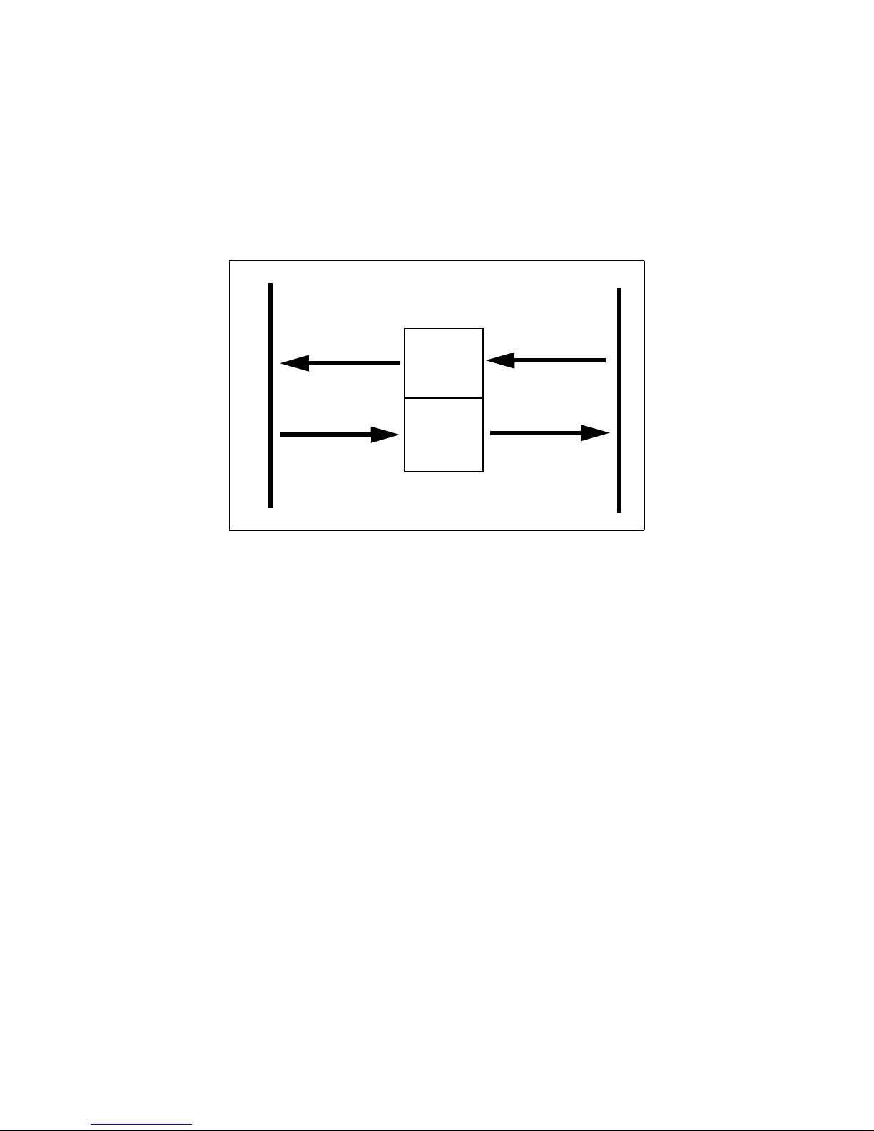
Theory of Operation
The Anybus-X provides centralized data storage, the “PassageWayTM”, for data
that is shared between the DeviceNet and Ethernet networks. Data is placed into
the PassageWay by one network interface, allowing the data to be read through the
other network interface.
Module Description 1-2
PassageWay
Input Data
Output Data
Input
Table
Output
Input Data
DeviceNet
Output Data
Table
Ethernet
Figure 1-1 Anybus-X PassageWay Operation
The Anybus-X appears as a single device on either network using standard proto-
col mechanisms. No special, or extended, protocol features are required of the
devices on either network to read or write the data flowing through the Passage-
Way; all cross-network activity is transparent to the devices on either network.
© 2005 HMS Industrial Networks AB7607 User manual

DeviceNet Features
• DeviceNet Master scanner functionality supporting up to 63 DeviceNet
• Explicit Messaging and Bit Strobe, Poll, and Change of State (COS) I/O
• Baud rates of 125, 250, and 500 Kbps.
• Automatic baud rate detection option may be enabled or disabled.
• Automatic Address Recovery can be configured to replace a faulted slave
• Configuration Recovery can be configured for slave devices so that a
Module Description 1-3
slave devices
connections.
device with a replacement device at the same MAC ID.
newly replaced slave can be configured to the same settings of the device
it replaces. Combined with Automatic Address Recovery this feature is
known as Automatic Device Recovery (ADR).
• Transfers 504 bytes Input (IN) and 500 bytes Output (OUT) I/O.
Ethernet Features
• Supports the EtherNet/IP protocol, Adapter Class with I/O Server, Mes-
• Supports the Modbus/TCP protocol with up to 8 simultaneous connec-
• Features UDP and TCP/IP protocol stack.
• Supports DHCP/Bootp and ARP for IP Address configuration.
sage Client, Message Server, and CIP Message Routing.
tions. Conforms to the Modbus/TCP specification 1.0.
© 2005 HMS Industrial Networks AB7607 User manual

IT-Features
Module Description 1-4
• The Anybus-X features a flexible file system with two security levels.
The size available for user files is approximately 1.4 Mbyte.
• An FTP server provides easy file management using standard FTP clients.
• A Telnet server featuring a command line interface similar to the MSDOS™ environment.
• A a flexible HTTP server (Web server) with Server Side Includes (SSI)
functionality. These are commands to the web server embedded in the
HTML code. This enables the user to access the IN/OUT area using a customizeable web page interface.
• Firmware updates of the DeviceNet control portion of the Anybus-X
using the RS232 port and Anybus-X Configuration Tool.
• Email client capability. (The Anybus-X can only connect to mail servers
that do not require a username/password to access. A mail server such as
that used by many internet providers could not be used).
System Requirements
The following hardware and software components are needed to use the Anybus-
X Ethernet to DeviceNet device.
Required Hardware
• Anybus-X Ethernet to DeviceNet module.
• DeviceNet cabling, power, and devices forming a DeviceNet network.
• Ethernet cabling and power.
• PC or other controller with access to the Ethernet network.
• PC to execute DeviceNet Configuration Software. The DeviceNet slave
devices the Anybus-X communicates with are specified using a
DeviceNet Configuration Software Tool such as RSNetWorx for
DeviceNet from Rockwell Software or HMS AnyBus Net Tool-DN.
• 24 VDC power to the Anybus-X module. (DeviceNet power may be
used.)
© 2005 HMS Industrial Networks AB7607 User manual

Module Description 1-5
Optional Hardware
• A PC with a serial RS232 COM port to be used by the Anybus-X Configuration Tool Software for downloading firmware updates.
• RS232 null-modem cable (pins 2 and 3 swapped) from the PC to the Anybus-X module.
• DIN rail to mount the Anybus-X.
Required Software
• DeviceNet configuration software such as RSNetWorx for DeviceNet to
configure DeviceNet devices and Anybus-X’s DeviceNet operation.
RSLinx version 2.31 or later is required.
Optional Software
• Anybus-X Configuration Tool Software to update Anybus-X’s firmware.
© 2005 HMS Industrial Networks AB7607 User manual

Hardware Description
All connections, whether power or fieldbus, to the Anybus-X are made on one end
of the module. Phoenix connectors are provided for power and DeviceNet connec-
tions. A RJ-style connector is provided for Ethernet connection. There is a 9-pin
D-Subminiature connector for the auxiliary RS-232 port that is used for field firm-
ware upgrades. See “Installation” on page 2-1 for more details on the connectors.
There is an 8 position dip switch on the end of the module that can be used to
select a portion of a default IP address that may be used to permit an intranet con-
nection. See “Starting the Tool” on page 3-2 for more details on configuring the IP
address using the switches.
On the front of the Anybus-X module are 7 LEDs that are used for status indica-
Module Description 1-6
tion. These LEDs provide visual status for the overall module, the DeviceNet
interface, and the Ethernet interface. See “Anybus-X LEDs” on page 10-1 for
details on how the LEDs are used.
The back of the module has a DIN rail mount to allow the module to be mounted
on a DIN rail.
© 2005 HMS Industrial Networks AB7607 User manual

Chapter 2 Installation 2-1
Installation
Installation and Operation Requirements
•Power, input and output (I/O) wiring must be in accordance with Class 1, Division 2 wiring methods - article 501-4(b) of the National Electric Code,
NFPA 70 and in accordance with local codes.
•Warning - Explosion Hazard - Substitution of components may impair suitability for Class 1, Division 2.
•Warning - Explosion Hazard - When in hazardous locations turn off power
before replacing or wiring modules.
•Warning - Explosion Hazard - Do not disconnect equipment unless power has
been switched off or the area is known to be nonhazardous.
•Terminal tightening torque must be between 5-7 lbs-in (0.5-0.8 Nm).
•For use in Class 2 circuits only.
•Suitable for surrounding temperature of 65 degrees C maximum.
•Use 60/75 C copper wire only.
© 2005 HMS Industrial Networks
AB7607 User manual
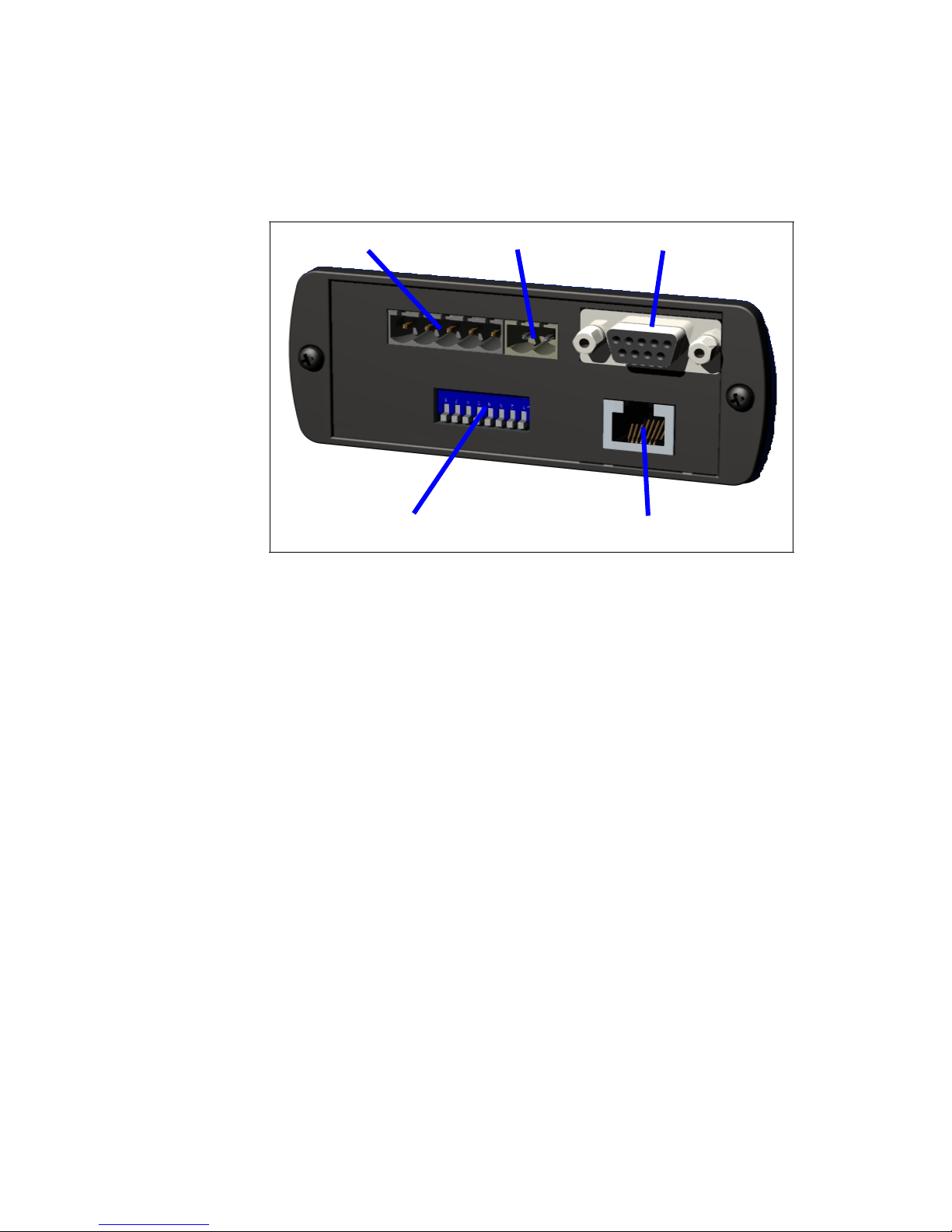
Power and Network Connections
The power and network connections to the Anybus-X are made on the end of the
module. Figure 2-1 indicates the location of each connector.
Installation 2-2
DeviceNet Power
Ethernet IP Address
Aux RS-232
Ethernet
Figure 2-1 Anybus-X Power and Network Connections
© 2005 HMS Industrial Networks AB7607 User manual

Connecting Power
The power connection is a 2-pin terminal block located on the end of the module.
The female terminal block connector is provided with the Anybus-X. Connections
to be made are illustrated in Figure 2-2.
Installation 2-3
24VDC Common
24 VDC +
Figure 2-2 Power Connection
The Anybus-X requires 24 volts DC power. The module will start immediately
when power is applied (There is no On/Off switch on the module).
© 2005 HMS Industrial Networks AB7607 User manual
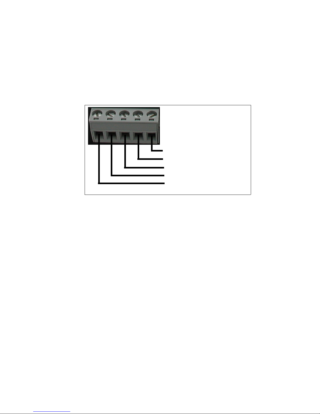
Connecting DeviceNet
The DeviceNet network connection is a 5-pin terminal block located next to the
power connection on the end of the module. The female terminal block connector
is provided with the Anybus-X. Connections to be made are illustrated in Figure
2-3.
Installation 2-4
(Red) Net Power 24VDC +
(White) CAN High
CAN Shield
(Blue) CAN Low
(Black) Net Power 24VDC Common
A 120 ohm termination resistor (not provided) may be required for proper net-
work termination. See the DeviceNet Specification for specific rules on
DeviceNet connections and termination.
For information on setting the DeviceNet network configuration (MAC ID, baud
rate, etc.), see “DeviceNet Network Configuration” on page 3-14.
Connecting to Ethernet
The Ethernet connection uses a standard RJ45 connector (not provided). This is
plugged into the socket on the end of the module.
For information on setting the Ethernet IP configuration (IP address, DHCP, etc.),
see “Starting the Tool” on page 3-2.
Figure 2-3 DeviceNet Connection
© 2005 HMS Industrial Networks AB7607 User manual

Chapter 3 Configuration 3-1
Configuration
This chapter describes how the Anybus-X Ethernet to DeviceNet Gateway is con-
figured. The next chapter walks the reader through the configuration of the Any-
bus-X using the commonly available configuration tools.
Anybus-X Configuration Tool (BWConfig)
The Anybus-X Configuration Tool allows you to configure the parameters associ-
ated with the Ethernet and DeviceNet network interfaces.
BWConfig is a Microsoft Windows application that communicates with the Any-
bus-X over a standard RS-232 serial link using the PC serial port. BWConfig is
compatible with Microsoft Windows 95, 98, NT, 2000, and XP.
Installing the Tool
Install BWConfig from the CD by running Setup.exe which is found in the CD's
root directory.
If you have downloaded BWConfig from the web site, unzip the downloaded file
into a temporary directory and run Setup.exe which is found in the temporary
directory.
Connecting to the Anybus-X Module
Connect the PC running BWConfig to the Anybus-X module using a standard
Null-Modem (pins 2 and 3 swapped) serial cable between the PC serial port and
the 9-pin D-Sub connector on the module. It does not matter which PC serial port
you use, BWConfig will scan each available port and detect the connection auto-
matically.
© 2005 HMS Industrial Networks
AB7607 User manual

Configuration 3-2
Starting the Tool
Launch BWConfig from the BridgeWay Configuration folder in the Windows
Start Menu.
When BWConfig is started, it will attempt to locate an Anybus-X module on one
of the PC serial ports. If a module is found, the status area of the tool will be
updated to show the module type and status of the module that was located.
If a module is not connected to the PC, or is powered off, when the tool is started,
the status area will indicate that no module was detected. Make sure that the mod-
ule is powered and the connection is made, then press the Refresh button on the
BWConfig tool bar; this will cause the tool to rescan the serial ports for a module.
© 2005 HMS Industrial Networks AB7607 User manual
Configuration 3-3
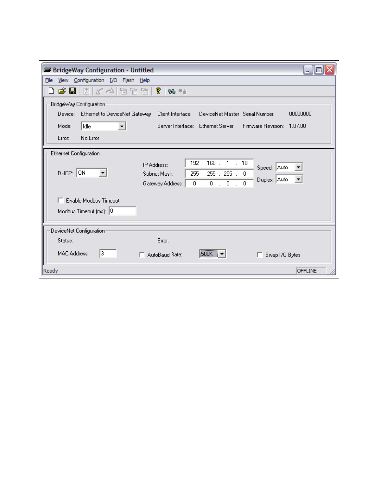
Configuration Tool User Interface
The Anybus-X Configuration Tool’s user interface is shown in Figure 3-1.
Figure 3-1 Configuration Tool User Interface
© 2005 HMS Industrial Networks AB7607 User manual

Configuration 3-4
Display Panes
The BWConfig display is divided into 3 panes.
Configuration Module type and status information about the
Anybus-X module that was detected.
Ethernet Configuration Configuration of Ethernet network parame-
ters.
DeviceNet Configuration Configuration of DeviceNet network parame-
ters and status of the network interface.
Tool Operations
The following operations are available through the BWConfig menus and tool bar.
New File Create a new configuration for the selected
type of module.
Open File Open a previously saved configuration.
Save File Save the current configuration to a file.
Refresh Device Status Refresh the module identity and status infor-
mation. This will update the current status
information shown by the tool. This can also
be used to start the detection process if a module has not been detected by the tool, or the
connection has been changed to a different
module.
Upload Configuration Read the configuration that is currently stored
in the Anybus-X module. This will overwrite
any configuration that is displayed on the
tool’s user interface.
Download Configuration Send the configuration shown on the tool’s
user interface to the Anybus-X module.
Offline Configuration Offline configuration will allow a configura-
© 2005 HMS Industrial Networks AB7607 User manual
tion to be created and saved without being
connected to a module.

Configuration 3-5
Flash Update Perform a field upgrade of the Anybus-X
module’s firmware.
Note: Care should be taken when upgrading
firmware, an incomplete update could cause
irreparable harm to the module.
© 2005 HMS Industrial Networks AB7607 User manual

Ethernet Network Configuration
Several methods may be used to set the IP Address. These methods include the
Configuration Tool, IP Address Configuration Switch, DHCP/Bootp protocol,
web browser, and the ARP protocol.
Setting the IP Address with BWConfig
The Ethernet network configuration pane in BWConfig contains the parameters
used to control the behavior of the Ethernet network interface. The parameters are
described in Table 3-1 below. Refer to Figure 3-1 to see how each parameter is
displayed on the user interface.
Parameter Description Allowable
Configuration 3-6
Range
DHCP Enable If DHCP is enabled, the module will receive
its IP configuration from a DHCP server on
the network.
If no DHCP server is available, the module
will revert to the last saved IP configuration.
IP Address The IP address the module will use on the Eth-
ernet network.
If DHCP is enabled, and a DHCP server is
found, this address is ignored. If a DHCP
server is not found, this address is used.
Subnet Mask The subnet mask the module will use on the
Ethernet network.
If DHCP is enabled, and a DHCP server is
found, this mask is ignored. If a DHCP server
is not found, this mask is used.
Gateway Address The IP address of the gateway module on the
network.
If DHCP is enabled, and a DHCP server is
found, this address is ignored. If a DHCP
server is not found, this address is used.
On or Off
Valid IP
address
Valid IP subnet mask
Valid IP
address
Network Speed The speed that the module will communicate
© 2005 HMS Industrial Networks AB7607 User manual
at on the Ethernet network.
If the network speed is set to Auto, the module
will auto-negotiate network speed.
Table 3-1 Ethernet Network Configuration Parameters
10, 100, or
Auto

Configuration 3-7
Parameter Description Allowable
Range
Network Duplex The duplex setting that the module will use to
communicate on the Ethernet network.
Half, Full, or
Auto
If the network duplex is set to Auto, the module will auto-negotiate duplex.
Modbus Timeout The Modbus Timeout option provides a means
0-65000ms
to detect the loss of the Modbus Scanner from
the Ethernet network. If the option is enabled,
and no Modbus requests are received within
the configured timeout period, the module
Run/Idle status will be set to Idle.
Table 3-1 Ethernet Network Configuration Parameters
Note: The Anybus-X will automatically reset after the Ethernet configuration is
downloaded from BWConfig.
Setting the IP Address with the Configuration Switch
If DHCP/BootP is not enabled or a server is not found and the Configuration
Switch is non zero, on power up the value of the switch is used to form an the IP
Address. The switch represents the binary value of the last byte in the 4 byte IP
address. In this case it is n.
IP address: 192.168.1.n
Subnet mask: 255.255.255.0
Gateway address: 0.0.0.0 (No gateway set)
This is a private address and can only be used on a local intranet. In such a case a
Web Browser such as Microsoft’s Internet Explorer can be used to access the
Anybus-X’s web page which allows changing the IP Address, Subnet mask, and
GateWay address settings.
Note: A non-zero DIP switch setting will override any other Ethernet configura-
tion that is done.
© 2005 HMS Industrial Networks AB7607 User manual

Configuration 3-8
DIP Switch Example
Figure 3-2 IP Configuration DIP Switch
The switches are set to 00010100 (20 decimal) (The switch position is shown in
White in the diagram.)
The IP address of the module will be set to 192.168.1.20.
Note: The numbers on the switches on the IP configuration DIP switch do NOT
correspond to bit locations in the address value. In fact, they are reversed. i.e. bit 0
is set by switch 8.
Setting the IP Address Using DHCP/BootP
When DHCP/BootP is enabled and a DHCP or BootP server is found, the IP
address, Subnet mask, and Gateway address is automatically configured by the
DHCP/BootP server. It can be enabled using the Anybus-X’s Settings web page.
Note: The use of DHCP is the default configuration for the Anybus-X as shipped.
© 2005 HMS Industrial Networks AB7607 User manual

Configuration 3-9
Setting the IP Address Using Address Resolution Protocol (ARP)
The module’s IP address can be changed using the ARP command from a PC. The
new IP address will be stored in non-volatile memory. ARP requires the module’s
Ethernet MAC Address that is printed on a label on the back of the module.
Note: ARP cannot be used to change the subnet mask and gateway address of the
Anybus-X. These can be configured using the Anybus-X’s Settings web page.
Switch all 8 switches of the IP Configuration DIP switch to the ON position.
Note: The ARP/Ping capability is disabled unless all switches are ON.
On a PC connected to the Anybus-X on Ethernet bring up an MS DOS™ window
and type:
arp -s <IP address> <MAC address>
The arp -s command will store the IP and MAC addresses in the PC’s ARP table.
Next type:
ping <IP address>
When the Ping command is executed, the PC sends this information to the module
using the MAC address. The module detects that it was addressed with the correct
MAC address and adopts the IP address sent by the PC.
Next type:
arp -d <IP address>
The arp -d will remove the static route from the PC’s ARP table.
Switch all 8 switches of the IP Configuration DIP switch to the OFF position to
disable the feature.
This method can be used to reconfigure a module that has been previously config-
ured, or even to reconfigure modules outside the host’s subnet.
© 2005 HMS Industrial Networks AB7607 User manual

Configuration 3-10
Arp/Ping Example:
The following commands will set the IP address of a Anybus-X with MAC
address 00-30-11-02-00-5E to 65.106.34.252.
arp -s 65.106.34.252 00-30-11-02-00-5e
ping 65.106.34.252
arp -d 65.106.34.252
© 2005 HMS Industrial Networks AB7607 User manual
Configuration 3-11
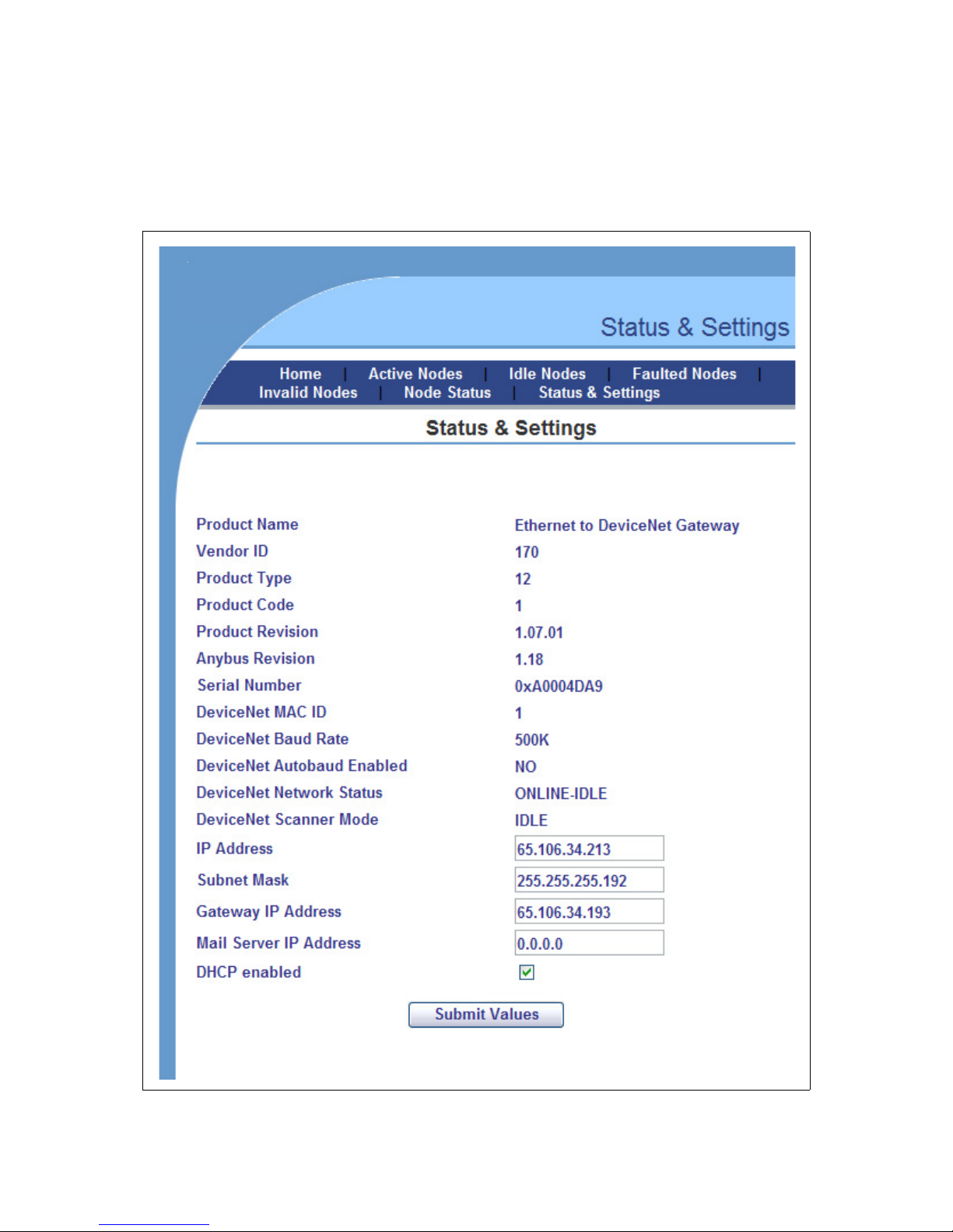
Setting the IP Address Using the Web Page
The ethernet addresses can also be configured using the Status and Settings web
page resident on the Anybus-X. The Status and Settings web page appears as
shown below.
© 2005 HMS Industrial Networks AB7607 User manual
Figure 3-3 Status and Settings Web Page

Configuration 3-12
The IP address, subnet mask, and default gateway address are displayed in the edit
boxes on the web page. Changing any values and clicking the Submit Values but-
ton will set the addresses in the Anybus-X. Note that a power cycle or module
reset is required for the changes to take effect.
The Reset Module button can be used to reset the Anybus-X from the web
browser. The Scanner Mode will display “RESETTING...” while the module
resets and comes back online. The web page will be refreshed after the module
has booted.
Note: If your web browser is configured to cache web pages, it may appear that
the Anybus-X has not changed address after you power cycle the module. Make
sure that the browsers settings are configured to always reload pages. On Internet
Explorer this is done in the Temporary Internet Files Settings dialog by selecting
the “Every Visit” option for when the browser should check for page changes.
© 2005 HMS Industrial Networks AB7607 User manual
Configuration 3-13
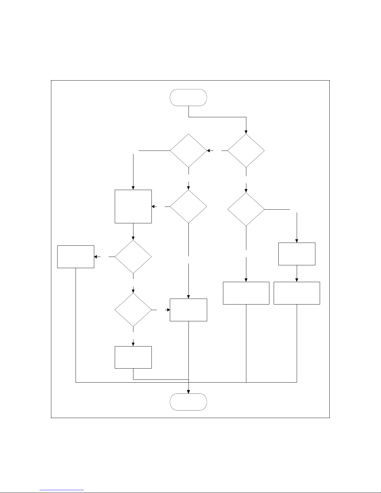
IP Address Initialization
The following flowchart describes how the IP configuration is determined when
the Anybus-X is powered up.
Sta rt
Val id
No
Configur ation
Fil e?
Yes
DIP Swi tch = 0
Use recei ved
confi guration
Yes
Request confi g
fr om DHCP/
BOOTP Server .
Timeout 30 secs
DHCP
Config
Received?
No
Val id
Confi gurati on
Fil e?
No
Remain offline
Yes
Yes
Yes
DHCP
Enabled?
No
Use configurati on
from file
No
DIP Swi t ch =
0xFF
No
IP = 192.168.1.n
Sub = 255.255.255.0
No Gat eway
Yes
Enabl e ARP/ Pi ng
Address Option
IP = 192.168.1.255
Sub = 255.255.255.0
No Gat eway
Figure 3-4 IP Configuration Initialization Sequence
© 2005 HMS Industrial Networks AB7607 User manual
End

DeviceNet Network Configuration
Setting the DeviceNet Configuration with BWConfig
The DeviceNet network configuration pane in BWConfig contains the parameters
used to control the behavior of the DeviceNet network interface. The parameters
are described in Table 3-2 below. Refer to Figure 3-1 to see how each parameter is
displayed on the user interface.
Parameter Description Allowable
Configuration 3-14
Range
MAC Address The network address the Anybus-X will use
on the DeviceNet network.
The MAC address factory default is 63.
Baud Rate The baud rate of the DeviceNet network.
The baud rate factory default is 125K
Auto Baud Enable or disable automatic baud rate detec-
tion on the Anybus-X.
The factory default setting for automatic baud
detection is Disabled.
Note: If the Anybus-X is the primary master
on the DeviceNet network, do not enable automatic baud detection.
Swap I/O Bytes Enable or disable I/O data byte swapping.
This option will swap bytes in the I/O tables
on 16-bit boundaries. This is helpful when
using Modbus/TCP, which expects data to be
stored in reverse byte orientation from
DeviceNet.
0-63
125K
250K
500K
Enabled or
Disabled
Enabled or
Disabled
Note: The Anybus-X will automatically reset after the DeviceNet configuration is
downloaded from BWConfig.
© 2005 HMS Industrial Networks AB7607 User manual
Do not enable byte swapping if EtherNet/IP is
used on the Ethernet side of the gateway.
Table 3-2 DeviceNet Network Configuration Parameters
 Loading...