

HMS Anybus Wireless Bridge Ethernet to WLAN User Manual
+$/067$'&+,&$*2.$5/658+(72.<2%(,-,1*0,/$1208/+286(&29(175<381(&23(1+$*(1
HMS Industrial Networks
Mailing address: Box 4126, 300 04 Halmstad, Sweden
Visiting address: Stationsgatan 37, Halmstad, Sweden
Connecting Devices
TM
E-mail: info@hms-networks.com
Web: www.anybus.com
User Manual
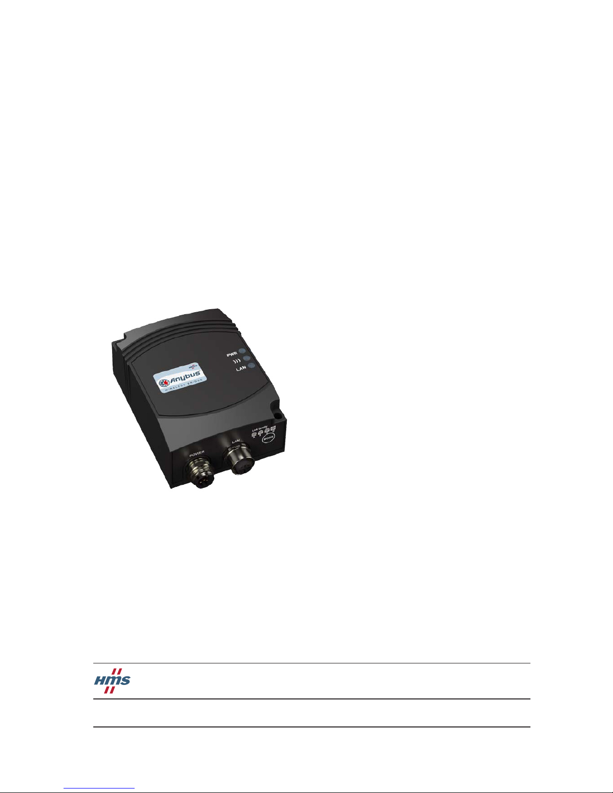
Anybus® Wireless Bridge
Ethernet to WLAN
Doc. ID HMSI-27-205
Rev. 1.20

Important User Information
This document is a product guide describing the main use cases for the Anybus Wireless Bridge - Ethernet to
WLAN module and how to configure it. It also contains general information about the product.
The reader of this document is expected to be familiar with high-level software design, and communication systems in general. The use of advanced Ethernet and Bluetooth specific functionality may require in-depth knowledge in the networking internals of these networks and/or information from the official specifications. In such
cases, the people responsible for the implementation of this product should either obtain the specifications to gain
sufficient knowledge or limit their implementation in such a way that this is not necessary.
Liability
Every care has been taken in the preparation of this product guide. Please inform HMS Industrial Networks AB of
any inaccuracies or omissions. The data and illustrations found in this document are not binding. We, HMS Industrial Networks AB, reserve the right to modify our products in line with our policy of continuous product development. The information in this document is subject to change without notice and should not be considered as a
commitment by HMS Industrial Networks AB. HMS Industrial Networks AB assumes no responsibility for any errors that may appear in this document.
There are many applications of this product. Those responsible for the use of this device must ensure that all the
necessary steps have been taken to verify that the applications meet all performance and safety requirements including any applicable laws, regulations, codes, and standards.
HMS Industrial Networks AB will under no circumstances assume liability or responsibility for any problems that
may arise as a result from the use of undocumented features, timing, or functional side effects found outside the
documented scope of this product. The effects caused by any direct or indirect use of such aspects of the product
are undefined, and may include e.g. compatibility issues and stability issues.
The examples and illustrations in this document are included solely for illustrative purposes. Because of the many
variables and requirements associated with any particular implementation, HMS Industrial Networks AB cannot
assume responsibility for actual use based on these examples and illustrations.
Intellectual Property Rights
HMS Industrial Networks AB has intellectual property rights relating to technology embodied in the product described in this document. These intellectual property rights may include patents and pending patent applications
in the US and other countries.
Trademark Acknowledgements
Anybus ® is a registered trademark of HMS Industrial Networks AB. All other trademarks are the property of their
respective holders.
Anybus Wireless Bridge - Ethernet to WLAN User Manual Rev 1.20
Copyright© HMS Industrial Networks AB
October 2013 Doc Id HMSI-27-205

Anybus Wireless Bridge - Ethernet to WLAN
Doc.Rev. 1.20
Doc.Id. HMSI-27-205
Important User Information
Liability........................................................................................................................................... 1
Intellectual Property Rights............................................................................................................... 1
Trademark Acknowledgements......................................................................................................... 1
Preface Safety Warnings & Restrictions
WARNINGS!............................................................................................................................... 1
RESTRICTIONS......................................................................................................................... 1
About This Document
Related Documents ..................................................................................................................................2
Document History ...................................................................................................................................2
Conventions & Terminology .................................................................................................................. 2
Support....................................................................................................................................................... 2
Chapter 1 Installation
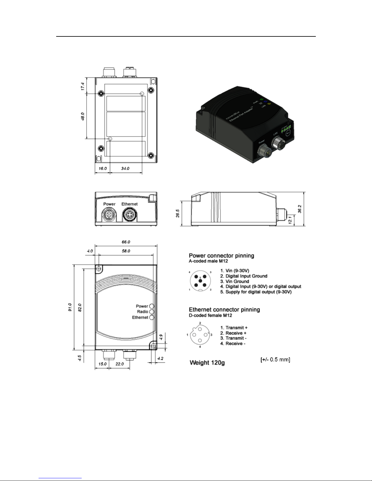
Power.......................................................................................................................................................... 4
Ethernet Interface .................................................................................................................................... 4
Status Indicators ....................................................................................................................................... 4
Chapter 2 General Concepts
Configuration Methods ........................................................................................................................... 5
Using SMART Configuration Mode ..................................................................................................... 5
Using the Web Configuration Interface ............................................................................................. 6
Reset to Factory Defaults.................................................................................................................. 8
Wireless LAN Modes..................................................................................................................... 8
Wireless Bridge Modes ..................................................................................................................... 8
WLAN Security............................................................................................................................. 9
Table of Contents
Table of Contents

II
Doc.Id. HMSI-27-205
Anybus Wireless Bridge - Ethernet to WLAN
Doc.Rev. 1.20
Chapter 3 Supported Use Cases
Two Wireless Bridges Connected as Ethernet Bridge - Alternative 1 ........................................... 11
Overview ........................................................................................................................................11
Set Up the Use Case ...................................................................................................................... 11
Two Wireless Bridges Connected as Ethernet Bridge - Alternative 2 ........................................... 13
Overview ........................................................................................................................................13
Set Up the Use Case ...................................................................................................................... 13
Two Wireless Bridges Connected as Ethernet Bridge - Alternative 3 ........................................... 15
Overview ........................................................................................................................................15
Set Up the Use Case ...................................................................................................................... 15
Two Wireless Bridges in Client Mode - Alternative 1 ...................................................................... 17
Overview ........................................................................................................................................17
Set Up the Use Case ...................................................................................................................... 17
Two Wireless Bridges Connected in Client Mode - Alternative 2.................................................. 18
Overview ........................................................................................................................................18
Set Up the Use Case ...................................................................................................................... 18
PC Connected Wirelessly to Wireless Bridge
- Alternative 1..........................................................................................................................................19
Overview ........................................................................................................................................19
Set Up the Use Case ...................................................................................................................... 19
PC Connected Wirelessly to Wireless Bridge
- Alternative 2..........................................................................................................................................20
Overview ........................................................................................................................................20
Set Up the Use Case ...................................................................................................................... 20
Multiple Ethernet Devices Connected in Client Mode - Alternative 1.......................................... 21
Overview ........................................................................................................................................21
Set Up the Use Case ...................................................................................................................... 21
Multiple Ethernet Devices Connected in Client Mode - Alternative 2.......................................... 22
Overview ........................................................................................................................................22
Set Up the Use Case ...................................................................................................................... 22
One or More Wireless Bridges Connected to a Wired Infrastructure through WLAN.............. 23
Overview ........................................................................................................................................23
Set Up the Use Case ...................................................................................................................... 23
External WLAN Client Connected to a Wireless Bridge................................................................. 24
Overview ........................................................................................................................................24
Set Up the Use Case ...................................................................................................................... 24
Multiclient Mode ....................................................................................................................................25
Overview ........................................................................................................................................25
Set Up the Use Case ...................................................................................................................... 25
Seamless Roaming and Redundancy ................................................................................................... 26
Overview ........................................................................................................................................26
Set Up the Use Case ...................................................................................................................... 31
Limitations .................................................................................................................................... 31
Appendix 4 Legal and Regulatory
ICC and FCC Compliance .................................................................................................................... 32
FCC Statement.............................................................................................................................. 32
Declaration of Conformity....................................................................................................................33
Licenses....................................................................................................................................................34

Doc.Id. HMSI-27-205
Anybus Wireless Bridge - Ethernet to WLAN
Doc.Rev. 1.20
Preface
P. P r e f a c e
P.1 Safety Warnings & Restrictions
This equipment is suitable for use in Class I, Division 2, Groups A, B, C and D, or non-hazardous locations only. The combinations of equipment in your own system will be subject to investigation by the
local Authority Having Jurisdiction at the time of installation.
P.1.1 WARNINGS!
EXPLOSION HAZARD! - Do not disconnect equipment unless power has been removed or the area
is known to be non-hazardous.
EXPLOSION HAZARD! - Substitution of any components may impair the suitability for Class I, Division 2.
Warning: This is a class A product.. In a domestic environment, this product may cause radio interference in which case the user may be required to take adequate measures.
P.1.2 RESTRICTIONS
Wiring terminals must be marked to indicate proper connections for the input power, output power, and
control circuits.
Field wiring terminals may use copper conductors only, wire size AWG 14, minimum temperature rating
60ºC.
This equipment is suitable for use in an ambient temperature of max 65ºC.
ESD Note: This product contains ESD (Electrostatic Discharge) sensitive parts that may be damaged
if ESD control procedures are not followed. Static control precautions are required when handling the
product. Failure to observe this may cause damage to the product.
P.2 About This Document
This document describes the various configurations available for this product and how to configure
them. For more information, documentation etc., please visit the HMS web site:
www.hms-networks.com.
P.3 Related Documents
Document Author
Quick Setup Guide, Anybus Wireless Bridge - Ethernet to WLAN HMS
AT Command Specification for Anybus Wireless Bridge - Ethernet to WLAN HMS

Preface 2
Doc.Id. HMSI-27-205
Anybus Wireless Bridge - Ethernet to WLAN
Doc.Rev. 1.20
P.4 Document History
Summary of Recent Changes (1.10 ... 1.20)
Revision List
P.5 Conventions & Terminology
The following conventions are used throughout this manual:
• Numbered lists provide sequential steps.
• Bulleted lists provide information, not procedural steps.
• The terms ‘Anybus’ or ‘module’ refers to the Anybus module.
• The terms ‘host’ or ‘host application’ refers to the device that hosts the Anybus module.
• Hexadecimal values are written in the format NNNNh, where NNNN is the hexadecimal value.
P.6 Support
For contact information and support, please refer to the contact and support pages at
www.hms-networks.com
Change Page(s)
Added safety warnings P1
Revision Date Author(s) Chapter(s) Description
1.00 2011-03-22 KaD - First official release
1.10 2012-04-20 KaD All Converted to Framemaker, minor updates and corrections
1.20 2013-10-09 SDa P Added safety warnings.
Doc.Id. HMSI-27-205
Anybus Wireless Bridge - Ethernet to WLAN
Doc.Rev. 1.20
Chapter 1
1. Installation

Installation 4
Doc.Id. HMSI-27-205
Anybus Wireless Bridge - Ethernet to WLAN
Doc.Rev. 1.20
1.1 Power
The table below shows the typical current at 24 V.
1.2 Ethernet Interface
The Ethernet interface supports 10/100 Mbps, with both MDI/MDI-X auto crossover and polarity correction.
1.3 Status Indicators
Operation Mean (mA) Max (mA)
Startup 58.8
Idle 58.7 58.8
Idle, Ethernet 69.0 69.1
Idle + 4xMode LEDs 74.2 74.3
Connecting 63.2 63.9
Connected, Data 63.2 64.8
Connected, Data, Ethernet 73.4 75.5
Connected, Data, Ethernet, 4xMode LEDs 78.6 80.7
Description Color Status Meaning
PWR Green On Supply voltage is present and application is running
PWR Green Off Supply voltage is not present, or no application is running
))) Blue/Purple/Red Blue A WLAN connection has been established
))) Blue/Purple/Red Flashing Blue WLAN data activity
))) Blue/Purple/Red Purple Attempt to establish a connection to another WLAN device
))) Blue/Purple/Red Red Error
))) Blue/Purple/Red Off No WLAN activity
LAN Yellow On Ethernet link is present
LAN Yellow Flashing Ethernet data activity
LAN Yellow Off No Ethernet connection

Doc.Id. HMSI-27-205
Anybus Wireless Bridge - Ethernet to WLAN
Doc.Rev. 1.20
Chapter 2
2. General Concepts
2.1 Configuration Methods
The Wireless Bridge supports four main methods for setting and configuring the module:
1. Smart mode
Use the buttons and LED’s on the Wireless Bridge to automatically set up the most common use
cases.
2. Web interface
An online web interface with the most common settings for the Wireless Bridge.
3. AT commands
Connect to the Wireless Bridge over Ethernet using TCP, or directly on Layer 2 and use a terminal such as Hyperterminal to issue AT commands. This method is mainly for more advanced settings and use cases, and is not described in this document. All commands available in the web
interface and much more are supported throught the use of AT commands.
4. The SNMP protocol
This will not be used or described in this document.
2.2 Using SMART Configuration Mode
If the Mode button is pressed within 5 seconds from power up, the Wireless Bridge will enter SMART
configuration mode. The LED’s above the button (A, B, C, and D) will show the mode currently selected. When the required mode is selected, it must be confirmed by holding in the Mode button for two
seconds. This will cause the LED’s to start flashing during the operation of the selected mode.

General Concepts 6
Doc.Id. HMSI-27-205
Anybus Wireless Bridge - Ethernet to WLAN
Doc.Rev. 1.20
There are currently 12 different modes available:
"Enable DHCP server" can be used to easily access the Wireless Bridge if the PC is using DHCP, without having to change the PC’s IP settings. This mode should only be used when the PC is connected
directly to the module, and not if the module is connected to a network using a DHCP server. Enable
this mode, then connect the Ethernet cable to the computer. The DHCP server will stay enabled until
a reboot.
How to use the other different modes for specific use cases is described later in this document.
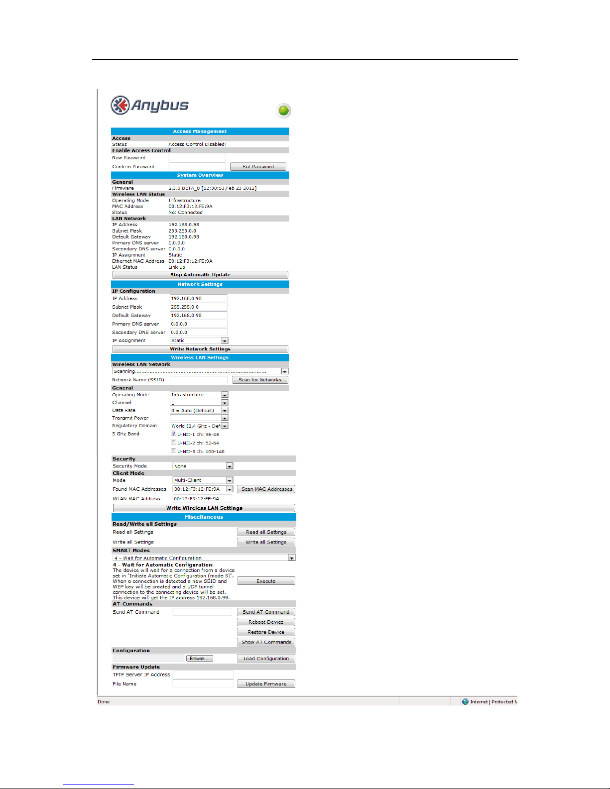
2.2.1 Using the Web Configuration Interface
By default, the Wireless Bridge has the following static IP settings;
• IP address: 192.168.0.99
• Subnet mask: 255.255.0.0
• Default gateway: 192.168.0.99.
To access the module using the web-based configuration interface, the computer must be set up in the
same network, e.g. IP address: 192.168.0.1 and subnet mask: 255.255.0.0.
Open a web browser and enter http://192.168.0.99 in the address field. From here, the most common
configuration parameters needed to set up a connection can be found.
Mode Description LEDs A B C D
1 Enable DHCP server A
2 Reset to factory defaults. This will reset the entire configu-
ration to factory defaults.
B
3 Reset IP settings to factory defaults. This will only reset the
IP settings to factory defaults.
A + B
4 Wait for Automatic configuration, ad-hoc mode. C
5 Initiate Automatic configuration, ad-hoc mode. A + C
6 Wait for Automatic configuration with Profinet optimiza-
tions, ad-hoc mode.
B + C
7 Initiate Automatic configuration with Profinet optimizations,
ad-hoc mode.
A + B + C
8 Wait for Automatic configuration, Managed mode. D
9 Initiate Automatic configuration, Managed mode. A + D
10 Initiate Automatic configuration, Managed mode, wired. B + D
11 Configure client mode. A + B + D
12 Initiate Automatic configuration, ad-hoc mode, multipoint. C + D
13 Reserved for future use. A + C + D
14 Reserved for future use. B + C + D
15 Reserved for future use. A + B + C + D
General Concepts 7
Doc.Id. HMSI-27-205
Anybus Wireless Bridge - Ethernet to WLAN
Doc.Rev. 1.20
An example of the web interface is shown below:

General Concepts 8
Doc.Id. HMSI-27-205
Anybus Wireless Bridge - Ethernet to WLAN
Doc.Rev. 1.20
2.2.2 Reset to Factory Defaults
It is possible to reset to the factory default settings in 4 different ways:
• Enter and confirm SMART mode 2.
• Issue AT&F.
•Hold the Mode button while the Wireless Bridge is starting. Note: Ensure that the Ethernet cable is disconnected, and that any firmware update program has been stopped.
• Press the Restore Device button in the AT-commands section.
2.2.3 Wireless LAN Modes
A Wireless LAN network can be set up in two main connection modes:
• Ad-hoc mode
This is typically used when two WLAN devices connect to each other without going via a WLAN
Access Point. In ad-hoc mode, only 802.11b transmission speeds are used, i.e. a maximum of 11
Mbit/s. The only encryption method supported is WEP.
• Managed (or Infrastructure) mode
This is typically used when a group of devices are connected through a common WLAN Access
Point. In this mode, all available transmission speeds can be used, up to a maximum of
54 Mbit/s. This also allows for user selection of encryption and authentication methods to use.
This means that use cases supporting Managed mode normally have higher throughput.
2.2.4 Wireless Bridge Modes
There are three main Wireless Bridge modes supported by the Wireless Bridge, and these are referred to
in all the use cases described later in this document.
1. Ethernet Bridge mode
In this mode, which is supported only between two Wireless Bridges, the Ethernet packages are
encapsulated in UDP packages and transferred transparently between the two modules. Devices
on both sides of the wireless link are completely unaware of the wireless connection.
2. Client mode
In this mode the Wireless Bridge acts as a wireless extension of the wired Ethernet device it is
connected to. The module is configured to take over (clone!) the MAC address of the connected
device. This means that only ONE Ethernet device can be connected to each module, and not
an Ethernet network with several devices connected through an Ethernet switch or hub. In
"Client Mode", the Wireless Bridge cannot be accessed over the Wireless LAN interface. However, if the Ethernet link is lost, the module will temporarily enter "Multiclient mode" and can
then be accessed again. When the Ethernet link is re-established, the module will revert to "Client
Mode".
3. Multiclient mode
In this mode, the Wireless Bridge acts as in Client mode, but with the addition that multiple devices using the IP layer can be connected.
Ethernet Bridge mode will introduce an extra overhead (because of the encapsulation) and will have a
significantly lower throughput than Client/Multiclient mode.
 Loading...