

Page 1

Anybus®Wireless Bridge
Ethernet–Bluetooth
®
USER MANUAL
HMSI-27-206 2.3 ENGLISH
Page 2

Important User Information
Liability
Every care has been taken in the preparation of this document. Please inform HMS Industrial Networks AB of any
inaccuracies or omissions. The data and illustrations found in this document are not binding. We, HMS Industrial
Networks AB, reserve the right to modify our products in line with our policy of continuous product development.
The information in this document is subject to change without notice and should not be considered as a commitment by HMS Industrial Networks AB. HMS Industrial Networks AB assumes no responsibility for any errors that
may appear in this document.
There are many applications of this product. Those responsible for the use of this device must ensure that all the
necessary steps have been taken to verify that the applications meet all performance and safety requirements including any applicable laws, regulations, codes, and standards.
HMS Industrial Networks AB will under no circumstances assume liability or responsibility for any problems that
may arise as a result from the use of undocumented features, timing, or functional side effects found outside the
documented scope of this product. The effects caused by any direct or indirect use of such aspects of the product
are undefined, and may include e.g. compatibility issues and stability issues.
The examples and illustrations in this document are included solely for illustrative purposes. Because of the many
variables and requirements associated with any particular implementation, HMS Industrial Networks AB cannot assume responsibility for actual use based on these examples and illustrations.
Intellectual Property Rights
HMS Industrial Networks AB has intellectual property rights relating to technology embodied in the product described in this document. These intellectual property rights may include patents and pending patent applications in
the USA and other countries.
Trademark Acknowledgements
Anybus®is a registered trademark of HMS Industrial Networks AB. All other trademarks are the property of their respective holders.
Copyright © 2016 HMS Industrial Networks AB. All rights reserved.
Anybus
®
Wireless Bridge Ethernet–Bluetooth®User Manual
HMSI-27-206 2.3
Page 3

Anybus®Wireless Bridge Ethernet–Bluetooth®User Manual HMSI-27-206 2.3
Table of Contents
Page
1 About This Document .................................................................................................... 3
1.1 Document history...........................................................................................................3
1.2 Conventions ..................................................................................................................4
2 Product Description ....................................................................................................... 5
2.1 LED Indicators ...............................................................................................................5
3 Installation ........................................................................................................................ 6
4 Startup and Configuration ............................................................................................ 7
4.1 Options for Device Configuration.....................................................................................7
4.2 Factory Reset ................................................................................................................7
4.3 SMART Configuration ....................................................................................................8
4.4 Web Configuration .........................................................................................................9
5 Configuration Examples..............................................................................................16
5.1 Example 1: Simple Ethernet Bridge ...............................................................................16
5.2 Example 2: Bluetooth Roaming .....................................................................................17
5.3 Example 3: PC Connecting to Wired Network via Bluetooth.............................................18
A Wireless Technology Basics ...................................................................................... 19
B Technical Data................................................................................................................20
B.1 Technical Specifications ...............................................................................................20
B.2 Internal Antenna Characteristics ...................................................................................21
B.3 Regulatory Compliance ................................................................................................ 22
B.4 Licenses .....................................................................................................................24
Page 4

This page intentionally left blank
Page 5

About This Document 3 (26)
1 About This Document
This manual describes how to install and configure Anybus Wireless Bridge Ethernet to
Bluetooth.
For additional related documentation and file downloads, please visit the support website at
www.anybus.com/support.
1.1 Document history
Summary of recent changes
Change Where (section no.)
Added info about Telnet access 4.1
Added explanation of Bluetooth EDR 4.4.1
Updated configuration examples
5
Added antenna characteristics B.2
Fixed typos etc.
—
Revision list
Version Date Author Description
1.00 2011-03-22 KaD First released version
1.10 2012-04-03 KaD Converted to FrameMaker, minor updates and corrections
1.20 2013-10-09 SDa Added safety warnings
2.0 2016-05-01 ThN Major rewrite, new structure and layout
2.1 2016-06-15 ThN Removed Bluetooth LE
Updated compliance information
2.2 2016-07-12 ThN Minor update
2.3 2016-07-14 ThN Minor update
Anybus
®
Wireless Bridge Ethernet–Bluetooth®User Manual HMSI-27-206 2.3
Page 6
About This Document 4 (26)
1.2 Conventions
Unordered (bulleted) lists are used for:
• Itemized information
• Instructions that can be carried out in any order
Ordered (numbered or alphabetized) lists are used for instructions that must be carried out in
sequence:
1. First do this,
2. Then open this dialog, and
a. set this option...
b. ...and then this one.
Bold typeface indicates interactive parts such as connectors and switches on the hardware, or
menus and buttons in a graphical user interface.
Monospaced text is used to indicate program code and other
kinds of data input/output such as configuration scripts.
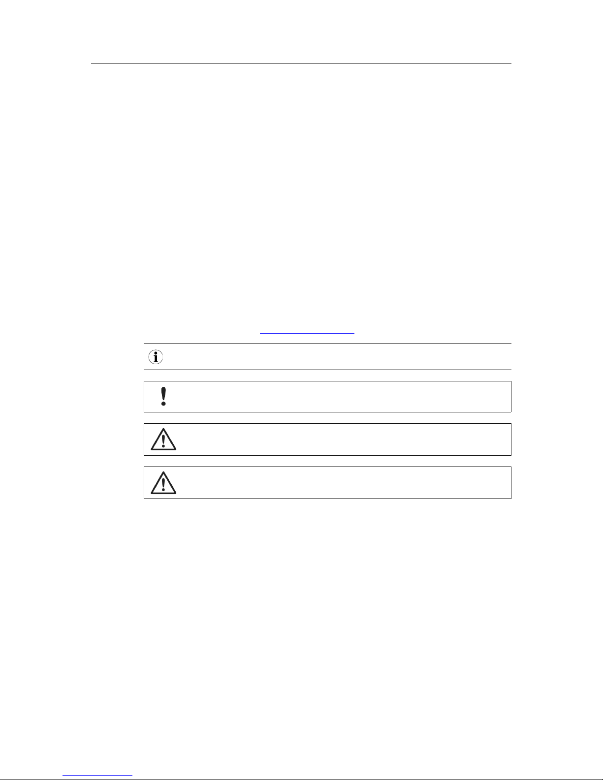
This is a cross-reference within this document: Conventions, p. 4
This is an external link (URL): www.hms-networks.com
This is additional information which may facilitate installation and/or operation.
This instruction must be followed to avoid a risk of reduced functionality and/or
damage to the equipment, or to avoid a network security risk.
Caution
This instruction must be followed to avoid a risk of personal injury.
WARNING
This instruction must be followed to avoid a risk of death or serious injury.
Anybus®Wireless Bridge Ethernet–Bluetooth®User Manual HMSI-27-206 2.3
Page 7
Product Description 5 (26)
2 Product Description
2.1 LED Indicators
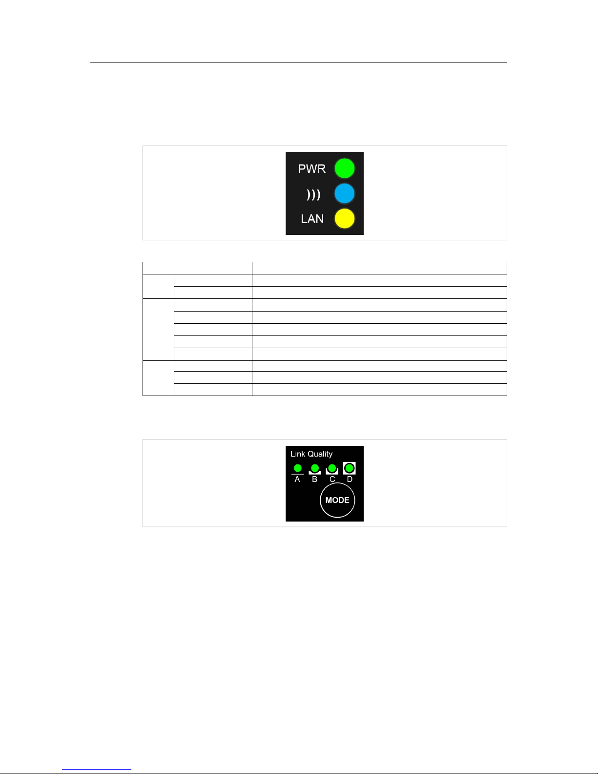
2.1.1 Status LED Indicators
Fig. 1 Status LED indicators
LED Indication Meaning
PWR
OFF No power or no application running
Steady Green Unit has power and application is running
)))
OFF No wireless activity
Steady Blue A wireless connection has been established
Flashing Blue Wireless data activity
Steady Purple Attempting to establish a wireless connection
Steady Red Wireless connection error
LAN
OFF No Ethernet connection
Steady Yellow Ethernet link is present
Flashing Yellow Ethernet data activity
2.1.2 A-B-C-D LED Indicators
Fig. 2 A-B-C-D LED indicators
The A-B-C-D LEDs are multi-functional. On a client operating in PANU mode they indicate the
wireless link quality: 4 LEDs lit = excellent signal. On the Access Point model they instead indicate the number of connected clients.
The LEDs are also used when selecting a SMART configuration mode.
Anybus®Wireless Bridge Ethernet–Bluetooth®User Manual HMSI-27-206 2.3
Page 8
Installation 6 (26)
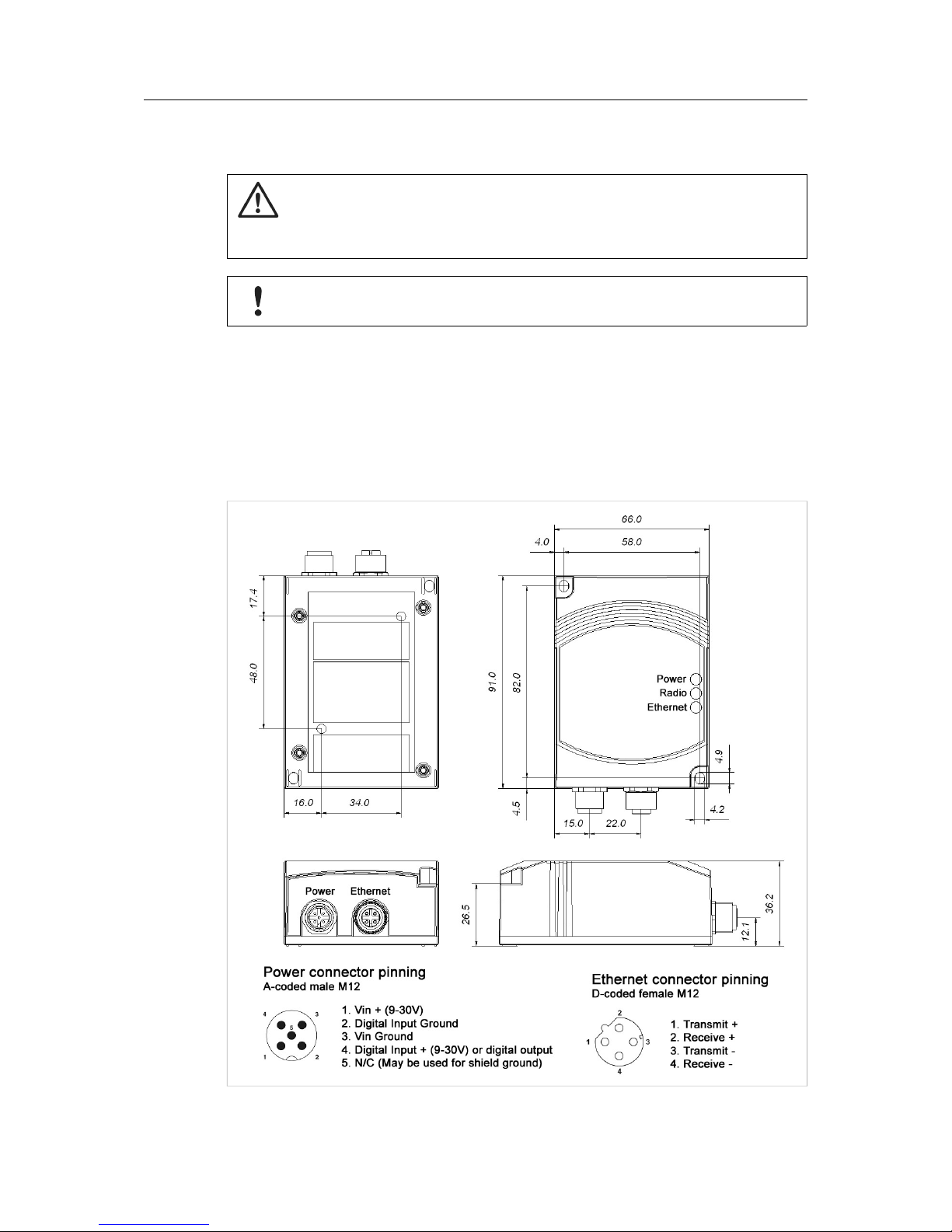
3 Installation
Caution
This equipment emits RF energy in the ISM (Industrial, Scientific, Medical) band.
Make sure that all medical devices used in proximity to this device meet
appropriate susceptibility specifications for this type of RF energy.
This product contains parts that can be damaged by electrostatic discharge (ESD).
Use ESD protective measures to avoid equipment damage.
Make sure that you have all the necessary information about the capabilities and restrictions of
your local network environment before installing the Anybus Wireless Bridge. Contact your network administrator if in doubt.
For optimal reception between units they should be oriented front-to-front with the line of sight
between them clear of obstructions. A minimum distance of 50 cm between the devices should
be observed to avoid interference.
See also Wireless Technology Basics, p. 19 and Internal Antenna Characteristics, p. 21.
Fig. 3 Installation drawing
Anybus
®
Wireless Bridge Ethernet–Bluetooth®User Manual HMSI-27-206 2.3
Page 9

Startup and Configuration 7 (26)
4 Startup and Configuration
4.1 Options for Device Configuration
SMART Configuration
Basic use cases can be set up quickly using the MODE button and the A-B-C-D LEDs to select
one of the SMARTconfiguration modes.
See SMART Configuration, p. 8.
Web Configuration
The built-in web server gives access to status information and configuration settings via a
graphical user interface.
See Web Configuration, p. 9.
AT Commands
Advanced configuration can be carried out by issuing AT (Hayes) commands in the Advanced
section of the web interface or using a Telnet connection to the Wireless Bridge on port 8080.
A list of supported ATcommands can be found at www.anybus.com/support.
4.2 Factory Reset
Anybus Wireless Bridge can be reset to the factory default settings in one of the following ways:
• Keeping the MODE button pressed while the unit is starting up
• Executing SMART Mode 2 (see SMART Configuration, p. 8)
• Issuing the ATcommand AT&F (see Settings – Advanced View, p. 15)
Factory Default Settings (IP Configuration)
IP Assignment: Static
IP Address: 192.168.0.98
Subnet Mask: 255.255.0.0
Default Gateway: 192.168.0.98
Web configuration password: (no password)
See Web Configuration, p. 9 for information about the default settings of all parameters.
Do not reset the Anybus Wireless Bridge while a firmware update is in progress.
As the default password setting is empty (no password), setting a secure password
when first configuring the unit is strongly recommended.
Anybus®Wireless Bridge Ethernet–Bluetooth®User Manual HMSI-27-206 2.3
Page 10

Startup and Configuration 8 (26)
4.3 SMART Configuration
Fig. 4 MODE button and LED indicators
1. Power on the Wireless Bridge, then immediately press and release MODE.
2. Press MODE repeatedly to cycle through the configuration modes until the desired
mode is indicated by the LED combination.
3. Press and hold MODE until the LEDs go out or blink, then release the button. The unit
will restart with the selected configuration.
If the unit is not restarted within 20 seconds of selecting a configuration mode it will exit SMART
configuration and return to the previous settings.
MODE
Operation Description
LED
A B C D
1
—
Enable DHCP server
2
—
Reset to factory defaults
3
—
Reset IP settings
4 PANU-PANU Wait for auto configuration
5 PANU-PANU Initiate auto configuration
6 PANU-PANU Initiate auto configuration (PROFINET priority)
7 PANU-NAP Initiate auto configuration
8 PANU-PANU + EDR Wait for auto configuration
9 PANU-PANU + EDR Initiate auto configuration (PROFINET priority)
10 NAP-PANU Wait for auto configuration
11–15 (reserved for future use)
SMART modes 4–9 cannot be used in the Access Point model.
PANU PAN User mode – the device can connect to another single Bluetooth device or to a
Bluetooth access point.
NAP Network Access Point mode – the device operates as a Bluetooth access point.
EDR Enhanced Data Rates (not supported by all Bluetooth devices)
Enable DHCP Server Activates a built-in DHCP server which makes it possible to access the Wireless
Bridge without manually configuring the IP address of the connecting computer. The
computer must be set up for DHCP and be connected directly to the unit, not through
a network. The DHCP server will stay enabled until the unit is restarted.
PROFINET priority PROFINET network traffic will be prioritized.
Anybus
®
Wireless Bridge Ethernet–Bluetooth®User Manual HMSI-27-206 2.3
Page 11

Startup and Configuration 9 (26)
4.4 Web Configuration
The web configuration interface can be accessed by entering the IP address of the Anybus
Wireless Bridge in any web browser that supports HTML5. The computer used for configuration
must be in the same subnet as the Wireless Bridge.
The default IP address is 192.168.0.98.
The initial page (Info page) shows the status and basic settings of the Wireless Bridge. The colors of the LAN Status and Bluetooth Status entries correspond to the LED indicators.
Click on Update Status to refresh the values once, or on Auto Update to make the values refresh every second.
To access the configuration page, click on Settings and enter the password to login.
The default password setting is empty (no password). Setting a secure password
when first configuring the unit is strongly recommended.
Fig. 5 Status page
Fig. 6 Login page
Anybus
®
Wireless Bridge Ethernet–Bluetooth®User Manual HMSI-27-206 2.3
Page 12

Startup and Configuration 10 (26)
4.4.1 Settings – Standard View
Fig. 7 Standard view
Top Menu
Info Return to the Info page but stay logged in.
Logout
Return to the Info page and log out.
Advanced view Open the Advanced view (see Settings – Advanced View, p. 15).
Load Configuration
Browse Select a saved configuration file.
Set & Reboot Apply the configuration and reboot.
Bottom Menu
Reload Settings Cancel all changes and reload the current configuration.
Write All Apply all changed settings to the Anybus Wireless Bridge. This has the same
function as clicking on Set in each of the different settings sections.
Reboot Restart the Anybus Wireless Bridge (without applying changes).
Anybus
®
Wireless Bridge Ethernet–Bluetooth®User Manual HMSI-27-206 2.3
Page 13

Startup and Configuration 11 (26)
Network – IP Configuration
IP Address The IP address of the Anybus Wireless Bridge.
Default: 192.168.0.98
Subnet Mask Subnet mask. Default: 255.255.0.0
Default Gateway IP address of the transition point to other network segments. Must also be set
when DHCP addressing is used.
Default: 192.168.0.98
IP Assignment Static (default): The unit is assigned the IP address set above.
DHCP: IP configuration settings are retrieved from a DHCP server.
Static & DHCP Server: The unit is assigned the IP address set in the IP
Address field and operates as DHCP server for devices connected to the LAN
port.
Set & Reboot Apply the changes and reboot.
Network – PROFINET
PROFINET Prioritization Enable/disable prioritization for PROFINET
PROFIsafe Enable/disable PROFIsafe functionality
Set Apply the changes (no reboot required).
Bluetooth – General
Operation Mode PANU: Client within a Personal Area Network (PAN) – can also be used for
point-to-point connections.
NAP: Network Access Point (“master” in a PAN) – up to seven connections can
be managed.
Max. Transmit Power Selection of the maximum transmission power (not including antenna gain)
Note: Bluetooth automatically reduces the actual transmission power to the
level required for the current connection. Manually reducing the transmission
power is only recommended for range limitation.
Data Policy Optimizing the data transmission method.
High Speed (default): All packet sizes (DM and DH) are selected automatically.
The system automatically selects the most suitable packet size for the Ethernet
packet.
Short Delay: All DM packet sizes and QoS prioritizing are used, resulting in
the lowest possible latency.
High Range: Only DM1 packets can be used. Transmission will be slower but
more stable, particularly in the event of long distances and/or demanding
environments.
EDR: Optimum transmission as long as the Bluetooth 2.1+EDR standard is
supported by both sides. EDR (Enhanced Data Rate) is a faster PSK
modulation scheme which supports up to 2 Mbit/s gross air bit rate.
Set & Reboot Apply the changes and reboot.
Anybus
®
Wireless Bridge Ethernet–Bluetooth®User Manual HMSI-27-206 2.3
Page 14

Startup and Configuration 12 (26)
Bluetooth – Security
Security Mode Activate/deactivate encryption and authentication.
ON (default): Encryption and authentication must be used. (GAP security
mode 3 with encryption)
OFF: No additional security mechanisms. Each device can log in without
having to enter a passkey. (GAP security mode 1 without encryption)
Passkey Key to be entered for authentication during connection establishment. Make
sure you choose a unique and secure key.
Set Apply the changes (no reboot required).
Bluetooth – WLAN Coexistence
Low Emission Mode OFF (default): LEM 0 – The behavior corresponds to that of the Bluetooth
standard. Enables operation with standard-compliant Bluetooth devices.
ON: LEM 3 – The device has less impact on the wireless channel during
connection establishment. This mode is particularly recommended for parallel
operation with WLAN networks.
Note: Both communication partners must operate in the same LEM mode.
Otherwise, connection establishment can take a very long time.
Exclude WLAN Channel Select WLAN channels that should not be used by the Bluetooth system
(WLAN black channel list).
A maximum of three WLAN channels can be hidden without restricting the
function of the Bluetooth system. By excluding WLAN channels, the available
bandwidth will be reduced and thus the number of Bluetooth systems that can
be operated in parallel.
WLAN channels should only be hidden if they are actually required for highavailability WLAN systems.
Set Apply the changes (no reboot required).
Anybus
®
Wireless Bridge Ethernet–Bluetooth®User Manual HMSI-27-206 2.3
Page 15

Startup and Configuration 13 (26)
Bluetooth – Connection
Connection Scheme
(PANU mode)
Connect to MAC: A direct connection is established to another device with a
specified MAC address.
Connect to Name (Best RSSI): Searches for Bluetooth devices with a
specified name. Connection will then be established with the device that has
the highest receive field strength.
Connect to Name (Fast): Establishes a connection to the first device
responding with the specified name. This mode is faster but does not always
ensure optimum connection.
Connect to Name (P2P only): Attempts to establish a connection with the first
responding device. If the device name does not match the specified , the
connection attempt will be aborted.
Connections can be established very quickly with this mode, but only if there
are no other visible devices.
Connection Scheme
(NAP mode)
Wait (MAC): Other devices can connect to the access point quickly based on
its MAC address.
Wait (Name): The access point waits for connection requests based on the
name entered in the Local Name field.
Connect To (PANU mode) Select PANU when connecting to another Bluetooth client device.
Select NAP when connecting to a Bluetooth access point.
MAC Address/Name
(PANU mode)
The MAC address or Bluetooth device name to connect to. Click on Scan to
scan for devices, or enter the MAC address or device name manually.
Local Name (NAP mode) The name used to identify the Wireless Bridge to other Bluetooth devices when
operating in access point mode.
Set Apply the changes (no reboot required).
To establish a connection based on name, a device must be able to respond to a scan (visible).
A device is only visible as long as the maximum number of connections has not been reached.
Bluetooth – Roaming (PANU mode)
Link Sensitivity Long Range: Maintain the current connection as long as possible.
Medium: Default setting.
High Speed: Switch to a device with higher RSSI as soon as possible.
Using the same setting for both the roaming and the network devices is
recommended.
A time limit for changing from one connection to another when roaming cannot be ensured in
Bluetooth networks. Roaming times will increase with higher network utilization.
Anybus®Wireless Bridge Ethernet–Bluetooth®User Manual HMSI-27-206 2.3
Page 16

Startup and Configuration 14 (26)
SMART Mode Configuration
SMART Modes See SMART Configuration, p. 8.
Execute Apply the selected SMART configuration mode and reboot.
Service – Change Password
New Password Enter a new password for the web configuration interface.
Confirm Password Enter the new password again.
Set Confirm the new password (it will be required on the next login attempt).
Service – System Identification
Device Name A name for the device.
Description A short description of the device.
Physical Location The location of installation.
Device Contact Contact person (including e-mail, phone number, etc.).
General Data Additional information about the device.
Set Apply the changes (no reboot required).
Miscellaneous
Event Subscriber Activate sending of system events via TCP or Syslog.
Value Select which values to send: Receive quality (RSSI), Connection, or both
IP Address (Syslog only) The IP address of the Syslog server.
Set Apply the changes (no reboot required).
Export Configuration
Export configuration Save the current configuration settings as ATcommands in a text file.
Anybus
®
Wireless Bridge Ethernet–Bluetooth®User Manual HMSI-27-206 2.3
Page 17

Startup and Configuration 15 (26)
4.4.2 Settings – Advanced View
Fig. 8 Advanced view
AT Commands
AT Commands Enter AT commands into the field, then click on Set to upload them to the
Wireless Bridge.
AT Response Shows a log of the latest AT commands and their responses.
Clear Clears the log window.
Firmware update from TFTP Server
Server IP Address Enter the IP address of the TFTP server that provides the firmware file.
File name Enter the filename of the firmware file.
Update Click on Update to upload the firmware to the Wireless Bridge.
Make sure that TFTP traffic (UDP port 69) is not blocked by a firewall.
Do not reset the Wireless Bridge during a firmware update.
Anybus®Wireless Bridge Ethernet–Bluetooth®User Manual HMSI-27-206 2.3
Page 18

Configuration Examples 16 (26)
5 Configuration Examples
The following configuration examples require a basic understanding of how to install and power
up Anybus Wireless Bridge and how to access and use SMART configuration modes. Read
sections Product Description and Startup and Configuration before you continue.
• All the examples start out from the factory default settings.
• Settings not mentioned in the examples should normally be left at their default values.
• The Ethernet networks in the examples use static IP addressing within the default subnet range of the Wireless Bridge.
• The computer used for web configuration must be in the same subnet as the Wireless
Bridge being configured.
5.1 Example 1: Simple Ethernet Bridge
Fig. 9 Two Anybus Wireless Bridges used as an Ethernet bridge
This example describes two Wireless Bridges in PANU mode connecting two Ethernet network
segments.
1. Reset both Wireless Bridges to the factory default settings.
2. On the first Wireless Bridge, activate SMART mode 4 (LED C).
The LED will blink while the unit is waiting for a connection.
3. On the second Wireless Bridge, activate SMART mode 5 (LED A+C).
The LEDs will blink until the units have connected.
4. When the Wireless Bridges have connected successfully the ))) LED on both units will
show a steady blue light. The first unit will have IP address 192.168.0.98 and the second 192.168.0.99.
Anybus®Wireless Bridge Ethernet–Bluetooth®User Manual HMSI-27-206 2.3
Page 19

Configuration Examples 17 (26)
5.2 Example 2: Bluetooth Roaming
Fig. 10 Roaming between multiple Wireless Bridges
This example describes a Wireless Bridge roaming between two or more Wireless Bridges connected to a local network.
1. Reset all the Wireless Bridges to the factory default settings.
2. Open the web interface of the roaming Wireless Bridge and set up the following
configuration:
Parameter Value
Bluetooth - Connection
Connection Scheme Connect to name (Best RSSI)
Connect To PANU
Name The Bluetooth device name for the other Wireless Bridges.
Click on Scan to detect the other Wireless Bridges, or set the name
manually. (Default: Wireless Bridge ETH-BT)
3. Click on the Set button next to the Name field to save the configuration. The device will
immediately try to connect to the Wireless Bridge that has the strongest signal (RSSI)
of those with a matching device name.
Anybus®Wireless Bridge Ethernet–Bluetooth®User Manual HMSI-27-206 2.3
Page 20

Configuration Examples 18 (26)
5.3 Example 3: PC Connecting to Wired Network via Bluetooth
Fig. 11 PC connecting to a wired network via a Bluetooth Wireless Bridge
This configuration example describes a computer using Bluetooth to connect to an Ethernet network via a Wireless Bridge.
The example shows how to connect to a Bluetooth device in Windows 7. Please refer to the documentation for the operating system of your computer on how to set up Bluetooth networking.
1. Reset the Wireless Bridge to the factory default settings.
2. Open the network settings on the computer and connect to the Bluetooth PANU device
with the name of the Wireless Bridge (Wireless Bridge ETH-BT).
Anybus®Wireless Bridge Ethernet–Bluetooth®User Manual HMSI-27-206 2.3
Page 21

Appendix A: Wireless Technology Basics 19 (26)
A Wireless Technology Basics
Wireless technology is based on the propagation and reception of electromagnetic waves.
These waves respond in different ways in terms of propagation, dispersion, diffraction and reflection depending on their frequency and the medium in which they are travelling.
To enable communication there should optimally be an unobstructed line of sight between the
antennas of the devices. However, the so called Fresnel Zones should also be kept clear from
obstacles, as radio waves reflected from objects within these zones may reach the receiver out
of phase, reducing the strength of the original signal (also known as phase cancelling).
Fresnel zones can be thought of as ellipsoid three-dimensional shapes between two wireless
devices. The size and shape of the zones depend on the distance between the devices and on
the signal wave length. As a rule of thumb, at least 60 % of the first (innermost) Fresnel zone
must be free of obstacles to maintain good reception.
Fig. 12 Fresnel zones
Area to keep clear of obstacles (first Fresnel zone)
Distance (d)
Fresnel zone radius (r)
2.4 GHz (WLAN or Bluetooth) 5 GHz (WLAN)
100 m 1.7 m 1.2 m
200 m 2.5 m 1.7 m
300 m 3.0 m 2.1 m
400 m 3.5 m 2.4 m
The wireless signal may be adequate even if there are obstacles within the Fresnel zones, as it
always depends on the number and size of the obstacles and where they are located. This is
especially true indoors, where reflections on metal objects may actually help the propagation of
radio waves. To reduce interference and phase cancelling, the range may also need to be limited by reducing the transmission power. For determining the optimal configuration and placement of wireless devices it is therefore recommended to use a wireless signal analysis tool.
Anybus®Wireless Bridge Ethernet–Bluetooth®User Manual HMSI-27-206 2.3
Page 22

Appendix B: Technical Data 20 (26)
B Technical Data
B.1 Technical Specifications
Model Ethernet Bridge Access Point
Order code 023140 024130
Dimensions (L x W x
H)
91 x 66 x 36.2 mm
Weight 120 g 130 g
Operating temperature -30 to +65 °C
Storage Temperature -40 to +85 °C
Humidity RH 5–90 % non-condensing
Input voltage 9–30 V DC (SELV)
Power consumption 1.8 W (typical) — see also Typical current consumption at 24 VDC
Enclosure material Plastic
Mechanical rating IP65
Power connector M12
Ethernet connector M12
Mounting Screw holes for wall mounting
Antenna Internal External (RPSMA)
Transmission power 13 dBm max. 20 dBm max.
Receiver sensitivity -92 dBm max.
Maximum range 300 m
Maximum throughput 1 Mbps
Ethernet interface 10/100BASE-T with automatic MDI/MDIX cross-over
Ethernet protocols IP, TCP, UDP, LLDP, HTTP, ARP, DHCP client/server, DNS support, SNMP user
management and access control
Default IP address 192.168.0.98
Bluetooth specification Bluetooth 4.0
Basic Rate/EDR Core Configuration
Bluetooth profiles Generic Attribute Profile (GATT), Personal Area Networking Profile (PAN), PANU
and NAP roles (one connection)
Bluetooth security Simple pairing
Number of clients 1 7
Wireless certifications Europe (ETSI, R&TTE), USA (FCC/CFR 47 part 15 unlicensed modular transmit-
ter approval), Canada (IC, RSS), Japan (MIC)
Environm.
certifications
CE,
CULUS
, Haz.Loc Class 1 Div. 2
Typical current consumption at 24 VDC
Operation Mean (mA) Max (mA)
Startup
—
56.1
Idle 44.0 45.5
Idle, Ethernet 54.0 56.0
Idle + 4 x Mode LEDs 54.3 56.1
Connecting 60.1 60.6
Connected, Data 48.3 48.4
Connected, Data, Ethernet 54.2 54.4
Connected, Data, Ethernet, 4 x Mode LEDs 57.8 58.9
Anybus
®
Wireless Bridge Ethernet–Bluetooth®User Manual HMSI-27-206 2.3
Page 23

Appendix B: Technical Data 21 (26)
B.2 Internal Antenna Characteristics
Fig. 13 Longitudinal axis
Fig. 14 Transverse axis
Anybus
®
Wireless Bridge Ethernet–Bluetooth®User Manual HMSI-27-206 2.3
Page 24

Appendix B: Technical Data 22 (26)
B.3 Regulatory Compliance
EMC Compliance (CE)
The Anybus Wireless Bridge models 023140-B and 024130-B are in compliance with the RED
Directive 2014/53/EU through conformance with the following standards:
Effective use of frequency spectrum EMC
EN 300 328 V1.9.1 (2015-02) EN 301 489-1 V1.9.2 (2011-09)
EN 301 893 V1.8.1 (2015-03) EN 301 489-17 V2.2.1 (2012-09)
Safety EN 61000-6-2:2005
EN 62479:2010 EN 61000-6-3:2007 + A1:2011
EN 60950-1:2006 + A11:2009 + A1:2010 + A12:2011
+ A2:2013
IEC 60950-1:2005 + A1:2009 + A2:2013
The Declaration of Conformity is available at www.anybus.com/support.
Disposal and Recycling
You must dispose of this product properly according to local laws and regulations. Because this
product contains electronic components, it must be disposed of separately from household waste.
When this product reaches its end of life, contact local authorities to learn about disposal and recycling options, or simply drop it off at your local HMS office or return it to HMS.
For more information, see www.hms-networks.com.
UL Certification
This equipment is suitable only for use in Class I, Division 2, Groups A, B, C and D OR non-hazardous locations only. Combinations of equipment in your system are subject to investigation by
the local Authority Having Jurisdiction at the time of installation.
WARNING
EXPLOSION HAZARD - SUBSTITUTION OF ANY COMPONENTS MAY IMPAIR SUITABILITY
FOR CLASS I, DIVISION 2.
EXPLOSION HAZARD - DO NOT DISCONNECT EQUIPMENT UNLESS POWER HAS BEEN
SWITCHED OFF OR THE AREA IS KNOWN TO BE NONHAZARDOUS.
AVERTISSEMENT
RISQUE D’EXPLOSION – LE REMPLACEMENT DE TOUT COMPOSANTS INVALIDE LA
CERTIFICATION CLASS I, DIVISION 2.
RISQUE D’EXPLOSION – NE PAS DÉCONNECTER L’ÉQUIPEMENT TANT QUE
L’ALIMENTATION EST TOUJOURS PRÉSENTE OU QUE LE PRODUIT EST TOUJOURS EN
ZONE EXPLOSIVE ACTIVE.
Anybus®Wireless Bridge Ethernet–Bluetooth®User Manual HMSI-27-206 2.3
Page 25

Appendix B: Technical Data 23 (26)
FCC Compliance Statement
This equipment complies with FCC radiation exposure limits set forth for an uncontrolled environment. This equipment should be installed and operated with a minimum distance of 20 cm
between the radiator and your body.
This device complies with Part 15 of the FCC Rules. Operation is subject to the following two
conditions:
1. this device may not cause harmful interference, and
2. this device must accept any interference received, including interference that may
cause undesired operation.
This equipment contains FCC ID: PVH0946
Any changes or modifications not explicitly approved by HMS Industrial Networks
AB could cause the module to cease to comply with FCC rules part 15, and thus
void the user's authority to operate the equipment.
Industry Canada Statement
This equipment complies with IC RSS-102 radiation exposure limits set forth for an uncontrolled
environment.
This equipment should be installed and operated with a minimum distance of 20 cm between
the radiator and your body.
Operation is subject to the following two conditions:
1. this device may not cause harmful interference, and
2. this device must accept any interference received, including interference that may
cause undesired operation
Cet équipement est conforme aux limites d'exposition de rayonnement d'IC RSS-102 déterminées pour un environnement non contrôlé. Cet équipement devrait être installé et actionné avec
la distance minimum 20 cm entre le radiateur et votre corps.
Son utilisation est soumise aux deux conditions suivantes:
1. Cet appareil ne doit pas causer d’interférences et
2. il doit accepter toutes interférences reçues, y compris celles susceptibles d’avoir des effets indésirables sur son fonctionnement.
This equipment contains IC ID: 5325A-0946
Japan Radio Equipment Compliance (MIC)
Contains MIC ID: R 204-210003
Anybus®Wireless Bridge Ethernet–Bluetooth®User Manual HMSI-27-206 2.3
Page 26

Appendix B: Technical Data 24 (26)
B.4 Licenses
This product contains software under the following licenses:
Copyright (c) 2001–2004 Swedish Institute of Computer Science. All rights reserved.
Redistribution and use in source and binary forms, with or without modification, are permitted
provided that the following conditions are met:
1. Redistribution of source code must retain the above copyright notice, this list of conditions
and the following disclaimer.
2. Redistribution in binary form must reproduce the above copyright notice, this list of
conditions and the following disclaimer in the documentation and/or other materials provided
with the distribution.
3. The name of the author may not be used to endorse or promote products derived from this
software without specific prior written permission.
THIS SOFTWARE IS PROVIDED BY THE AUTHOR “AS IS” AND ANY EXPRESS OR IMPLIED
WARRANTIES, INCLUDING, BUT NOT LIMITED TO, THE IMPLIED WARRANTIES OF
MERCHANTABILITYAND FITNESS FOR A PARTICULAR PURPOSE ARE DISCLAIMED. IN NO
EVENT SHALL THE AUTHOR BE LIABLE FOR ANY DIRECT, INDIRECT, INCIDENTAL, SPECIAL,
EXEMPLARY, OR CONSEQUENTIAL DAMAGES (INCLUDING, BUT NOT LIMITED TO,
PROCUREMENT OF SUBSTITUTE GOODS OR SERVICES; LOSS OF USE, DATA, OR PROFITS;
OR BUSINESS INTERRUPTION) HOWEVER CAUSED AND ON ANY THEORY OF LIABILITY,
WHETHER IN CONTRACT, STRICT LIABILITY, OR TORT (INCLUDING NEGLIGENCE OR
OTHERWISE) ARISING IN ANY WAY OUT OF THE USE OF THIS SOFTWARE, EVEN IF
ADVISED OF THE POSSIBILITY OF SUCH DAMAGE.
This file is part of the lwIP TCP/IP stack.
Author: Adam Dunkels adam@sics.se
Anybus®Wireless Bridge Ethernet–Bluetooth®User Manual HMSI-27-206 2.3
Page 27

This page intentionally left blank
Page 28

last page
HMSI-27-206 2.3.1575 / 2016-07-14 16:18 © 2016 HMS Industrial Networks AB
 Loading...