

HMS Anybus Wireless Bolt RJ45 PoE User Manual
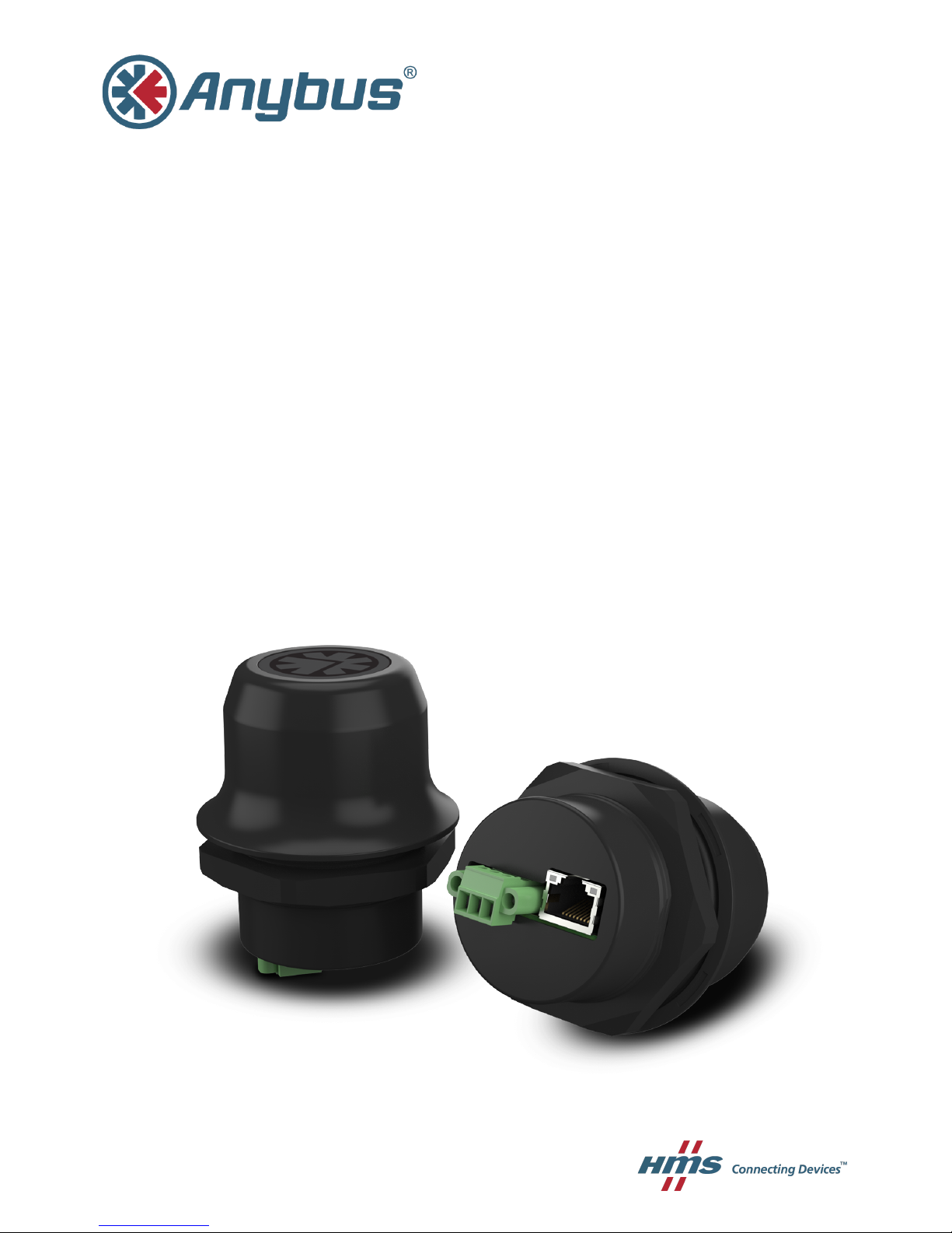
Anybus®Wireless Bolt™RJ45 PoE
USER MANUAL
SCM-1202-088 EN 1.1 ENGLISH

Important User Information
Liability
Every care has been taken in the preparation of this document. Please inform HMS Industrial Networks AB of any
inaccuracies or omissions. The data and illustrations found in this document are not binding. We, HMS Industrial
Networks AB, reserve the right to modify our products in line with our policy of continuous product development.
The information in this document is subject to change without notice and should not be considered as a
commitment by HMS Industrial Networks AB. HMS Industrial Networks AB assumes no responsibility for any errors
that may appear in this document.
There are many applications of this product. Those responsible for the use of this device must ensure that all the
necessary steps have been taken to verify that the applications meet all performance and safety requirements
including any applicable laws, regulations, codes, and standards.
HMS Industrial Networks AB will under no circumstances assume liability or responsibility for any problems that
may arise as a result from the use of undocumented features, timing, or functional side effects found outside the
documented scope of this product. The effects caused by any direct or indirect use of such aspects of the product
are undefined, and may include e.g. compatibility issues and stability issues.
The examples and illustrations in this document are included solely for illustrative purposes. Because of the many
variables and requirements associated with any particular implementation, HMS Industrial Networks AB cannot
assume responsibility for actual use based on these examples and illustrations.
Intellectual Property Rights
HMS Industrial Networks AB has intellectual property rights relating to technology embodied in the product
described in this document. These intellectual property rights may include patents and pending patent applications
in the USA and other countries.
Anybus
®
is a registered trademark and Wireless Bolt™is a trademark of HMS Industrial Networks AB. All other
trademarks mentioned in this document are the property of their respective holders.
Anybus®Wireless Bolt™RJ45 PoE User Manual SCM-1202-088 EN 1.1

Anybus®Wireless Bolt™RJ45 PoE User Manual SCM-1202-088 EN 1.1
Table of Contents
Page
1 Preface ............................................................................................................................... 3
1.1 About This Document .....................................................................................................3
1.2 Document History ..........................................................................................................3
1.3 Document Conventions ..................................................................................................4
2 Description ....................................................................................................................... 5
2.1 Product Description........................................................................................................5
2.2 Bluetooth or WLAN? ......................................................................................................5
2.3 Model Name – Certification Identifier ...............................................................................6
3 Installation ........................................................................................................................ 7
3.1 Safety ...........................................................................................................................7
3.2 General Information .......................................................................................................7
3.3 Mechanical Installation ...................................................................................................8
3.4 Connectors....................................................................................................................9
3.5 RJ45 LED Indicators ....................................................................................................10
3.6 RESET Button ............................................................................................................. 11
4 Configuration .................................................................................................................12
4.1 General....................................................................................................................... 12
4.2 Web Interface .............................................................................................................. 13
4.3 Factory Restore ...........................................................................................................28
A Configuration Examples.............................................................................................. 29
A.1 Ethernet Bridge via WLAN or Bluetooth®........................................................................ 29
A.2 PROFINET networking via Bluetooth
®
............................................................................30
A.3 EtherNet/IP
™
Networking via Bluetooth®.........................................................................31
A.4 Ethernet network to existing WLAN ............................................................................... 32
A.5 Adding single Ethernet node to WLAN ........................................................................... 33
A.6 Accessing PLC via WLAN from Handheld Device...........................................................34
B Wireless Technology Basics ...................................................................................... 36
C Technical Data................................................................................................................ 37
C.1 Hardware Specifications ............................................................................................... 37
C.2 Communication ........................................................................................................... 38

This page intentionally left blank

Preface 3 (40)
1 Preface
1.1 About This Document
This manual describes how to install and configure Anybus Wireless Bolt RJ45 PoE.
For additional documentation and software downloads, FAQs, troubleshooting guides and
technical support, please visit www.anybus.com/support.
1.2 Document History
Version Date Description
1.0 2018-04-23 First release
1.1 2018-09-05 Updated for FW 1.6.3
Anybus
®
Wireless Bolt™RJ45 PoE User Manual SCM-1202-088 EN 1.1
Preface 4 (40)
1.3 Document Conventions
Ordered lists are used for instructions that must be carried out in sequence:
1. First do this
2. Then do this
Unordered (bulleted) lists are used for:
• Itemized information
• Instructions that can be carried out in any order
...and for action-result type instructions:
► This action...
➨ leads to this result
Bold typeface indicates interactive parts such as connectors and switches on the hardware, or
menus and buttons in a graphical user interface.
Monospaced text is used to indicate program code and other
kinds of data input/output such as configuration scripts.
This is a cross-reference within this document: Document Conventions, p. 4
This is an external link (URL): www.hms-networks.com
This is additional information which may facilitate installation and/or operation.
This instruction must be followed to avoid a risk of reduced functionality and/or
damage to the equipment, or to avoid a network security risk.
Caution
This instruction must be followed to avoid a risk of personal injury.
WARNING
This instruction must be followed to avoid a risk of death or serious injury.
Anybus®Wireless Bolt™RJ45 PoE User Manual SCM-1202-088 EN 1.1

Description 5 (40)
2 Description
2.1 Product Description
Anybus Wireless Bolt RJ45 PoE provides wireless communication over WLAN and/or
Bluetooth
®
to Ethernet networks.
It supports Power over Ethernet (PoE) in compliance with IEEE 802.3af/at, type 1 class 0
(<12 W), both midspan and endspan. It can optionally be connected to a separate 19–36 VDC
power source for redundancy.
Typical applications for Anybus Wireless Bolt RJ45 PoE include:
• Adding wireless cloud connectivity to industrial devices
• Accessing devices from a laptop, smartphone or tablet
• Ethernet cable replacement between devices
Note:
Bluetooth PAN (Personal Area Network) may not work with some devices due to different
implementations of Bluetooth by different manufacturers.
WLAN 5 GHz cannot be used at the same time as WLAN 2.4 GHz or Bluetooth.
2.2 Bluetooth or WLAN?
Use Bluetooth when...
• ...the wireless link has an Anybus Wireless Bridge II or Anybus Wireless Bolt at both ends.
• ...an interruption-free connection is more important than data throughput speed.
• ...interference robustness is important – e.g. in an industrial environment.
• ...a Profinet I/O cycle time or EtherNet/IP RPI of 64 ms or more is acceptable.
Use WLAN when...
• ...connecting to other types of wireless devices or a WLAN infrastructure.
• ...high data throughput speed is more important than connection reliability.
• ...large file transfers are expected.
• ...WLAN channel frequency planning is possible.
• ...a low Profinet I/O cycle time or EtherNet/IP RPI is desired.
Anybus®Wireless Bolt™RJ45 PoE User Manual SCM-1202-088 EN 1.1

Description 6 (40)
2.3 Model Name – Certification Identifier
The model name consists of a model prefix followed by two designators for interface
configuration and functionality.
Prefix AWB2 Anybus Wireless Bolt
Interface configuration A
B
Interface 18-pin socket
Interface RJ45 and 3-pin power socket
Functionality A
B
C
Ethernet
Ethernet and RS232/485
Ethernet and CAN
Example: AWB2AA = Anybus Wireless Bolt with18-pin plug connector and Ethernet
networking only.
Anybus®Wireless Bolt™RJ45 PoE User Manual SCM-1202-088 EN 1.1
Installation 7 (40)
3 Installation
3.1 Safety
Caution
This equipment emits RF energy in the ISM (Industrial, Scientific, Medical) band.
Make sure that all medical devices used in proximity to this device meet appropriate
susceptibility specifications for this type of RF energy.
This product is recommended for use in both industrial and domestic environments.
For industrial environments it is mandatory to use the functional earth connection to
comply with immunity requirements. For domestic environments the functional earth
must be used if a shielded Ethernet cable is used, in order to meet emission
requirements.
This product contains parts that can be damaged by electrostatic discharge (ESD).
Use ESD prevention measures to avoid damage.
See also additional safety instructions in the included compliance information.
3.2 General Information
Make sure that you have all the necessary information about the capabilities and restrictions of
your local network environment before installation.
The characteristics of the internal antenna should be considered when choosing the placement
and orientation of the unit.
For optimal reception, wireless devices require a zone between them clear of objects that could
otherwise obstruct or reflect the signal. A minimum distance of 50 cm between the devices
should also be observed to avoid interference.
See also Wireless Technology Basics, p. 36.
Anybus®Wireless Bolt™RJ45 PoE User Manual SCM-1202-088 EN 1.1
Installation 8 (40)
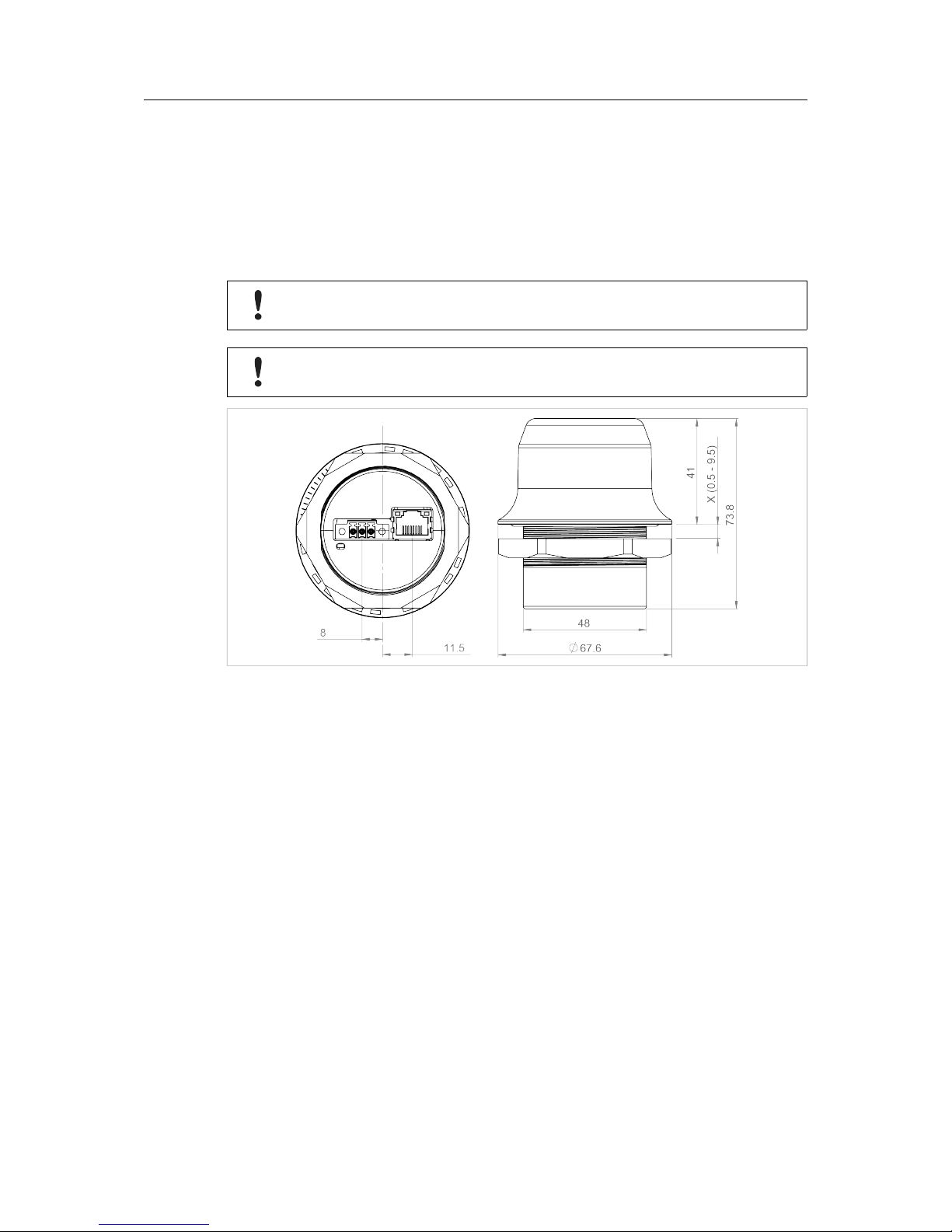
3.3 Mechanical Installation
The device is intended to be mounted on top of a machine or cabinet through an M50
(50.5 mm) hole using the included sealing ring and nut.
The top mounting surface (in contact with the sealing) must be flat with a finish equivalent to
Ra 3.2 or finer and cleaned and free from oils and greases.
Tightening torque: 5 Nm ±10 %.
Make sure that the sealing ring is correctly placed in the circular groove in the top
part of the housing before tightening the nut.
Always hold the BOTTOM part of the unit when untightening the nut, not the top
part (the cap).
Fig. 1 Installation drawing
All measurements are in mm.
Anybus®Wireless Bolt™RJ45 PoE User Manual SCM-1202-088 EN 1.1
Installation 9 (40)
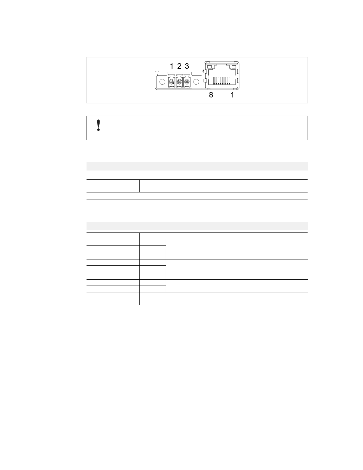
3.4 Connectors
Fig. 2 Connectors
Connecting power with reverse polarity or using the wrong type of power supply
may damage the equipment. Make sure that the power supply is connected
correctly and of the recommended type.
See also Technical Data, p. 37 regarding power supply requirements.
Power Connector (3-pin terminal block)
Pin Function
1
+
19–36 VDC
2
-
3 Functional Earth (FE)
FE must be connected on the power connector if not using PoE.
Ethernet Connector (RJ45 PoE)
Pin Data PoE
1 TD+ A+
Positive power from alt. A PSE
2 TD- A+
3 RD+ A- Negative power from alt. A PSE (with pin 6)
4 B+
Positive power from alt. B PSE
5 B+
6 RD- A- Negative power from alt. A PSE (with pin 3)
7 B-
Negative power from alt. B PSE
8 B-
Housing
Shield
Functional Earth (FE)
via 1 nF capacitor and 1 MΩ bleeder resistor
Shielded or unshielded Ethernet cables may be used.
Anybus®Wireless Bolt™RJ45 PoE User Manual SCM-1202-088 EN 1.1

Installation 10 (40)
3.5 RJ45 LED Indicators
Fig. 3 RJ45 LED indicators
LED A – LINK/ACTIVITY Function
Off No Ethernet link or no power
Yellow Ethernet link established
Yellow, flashing Ethernet traffic
LED B – STATUS Function
Off No power
Blue Connected on all configured wireless interfaces
Purple Trying to connect to WLAN/Bluetooth access point
Blue, slow blink Awaiting connections
Alternating blue/purple Connected on one interface and trying to connect or awaiting connections on
another
Purple, slow blink Awaiting connections on one interface and trying to connect on another
Purple, fast blink Scanning for Bluetooth devices or WLAN networks
Red, slow blink No configured wireless interface
Red Recoverable/unrecoverable fault
Anybus
®
Wireless Bolt™RJ45 PoE User Manual SCM-1202-088 EN 1.1

Installation 11 (40)
3.6 RESET Button
Fig. 4
The RESET button is located on the bottom of the unit.
When the unit is powered on, press and hold RESET for >10 seconds and then release it to
reset to the factory default settings.
Recovery Mode
If the web interface cannot be accessed, the unit can be reset by starting in Recovery Mode
and reinstalling the firmware using Anybus Firmware Manager II, which can be downloaded
from www.anybus.com/support.
To enter Recovery Mode, press and hold RESET during startup.
Firmware updates should normally be carried out through the web interface.
Recovery Mode should only be used if the unit is unresponsive and the web
interface cannot be accessed.
Anybus®Wireless Bolt™RJ45 PoE User Manual SCM-1202-088 EN 1.1
 Loading...