

HMS Anybus CompactCom 30, Anybus CompactCom 40 Migrating from Anybus CompactCom 30 to Anybus CompactCom 40
Page 1
Migrating from Anybus®CompactCom
™
30
to Anybus
®
CompactCom
DESIGN GUIDE
SCM-1202-043 1.1 ENGLISH
™
40
Page 2

Important User Information
Liability
Every care has been taken in the preparation of this document. Please inform HMS Industrial Networks AB of any
inaccuracies or omissions. The data and illustrations found in this document are not binding. We, HMS Industrial
Networks AB, reserve the right to modify our products in line with our policy of continuous product development.
The information in this document is subject to change without notice and should not be considered as a commitment by HMS Industrial Networks AB. HMS Industrial Networks AB assumes no responsibility for any errors that
may appear in this document.
There are many applications of this product. Those responsible for the use of this device must ensure that all the
necessary steps have been taken to verify that the applications meet all performance and safety requirements including any applicable laws, regulations, codes, and standards.
HMS Industrial Networks AB will under no circumstances assume liability or responsibility for any problems that
may arise as a result from the use of undocumented features, timing, or functional side effects found outside the
documented scope of this product. The effects caused by any direct or indirect use of such aspects of the product
are undefined, and may include e.g. compatibility issues and stability issues.
The examples and illustrations in this document are included solely for illustrative purposes. Because of the many
variables and requirements associated with any particular implementation, HMS Industrial Networks AB cannot assume responsibility for actual use based on these examples and illustrations.
Intellectual Property Rights
HMS Industrial Networks AB has intellectual property rights relating to technology embodied in the product described in this document. These intellectual property rights may include patents and pending patent applications in
the USA and other countries.
Migrating from Anybus®CompactCom™30 to Anybus®CompactCom™40 Design Guide SCM-1202-043 1.1
Page 3

Table of Contents
Page
1 Preface ............................................................................................................................... 5
1.1 About this Document ......................................................................................................5
1.2 Related Documents .......................................................................................................5
1.3 Document History ..........................................................................................................5
1.4 Document Conventions ..................................................................................................6
1.5 Terminology...................................................................................................................6
1.6 Trademark Information ...................................................................................................7
2 Background ...................................................................................................................... 8
2.1 Anybus CompactCom 30-Series .....................................................................................8
2.2 Upgrade to the 40-Series................................................................................................8
2.3 Access to Real-time Ethernet, IIoT and Advanced Security Features ..................................8
2.4 Recommendations from HMS Industrial Networks AB.......................................................8
3 Initial Considerations ..................................................................................................... 9
4 Hardware Compatibility ...............................................................................................10
4.1 Module........................................................................................................................10
4.2 Chip............................................................................................................................ 10
4.3 Brick ........................................................................................................................... 11
4.4 Host Application Interface .............................................................................................12
5 General Software........................................................................................................... 14
5.1 Extended Memory Areas ..............................................................................................14
5.2 Faster Ping-Pong Protocol............................................................................................ 14
5.3 Requests from CompactCom to Host Application During Startup .....................................14
5.4 Anybus Object (01h) ....................................................................................................14
5.5 Control Register CTRL_AUX-bit....................................................................................15
5.6 Status Register STAT_AUX-bit...................................................................................... 15
5.7 Control Register CTRL_R-bit ........................................................................................ 15
5.8 Modifications of Status Register, Process Data Read Area, and Message Data Read Area 15
6 Network Specific — BACnet/IP..................................................................................16
6.1 Network Configuration Object (04h)............................................................................... 16
6.2 Reduced Network Resources Due to Memory Constraints ..............................................16
7 Network Specific — CC-Link ......................................................................................17
7.1 Network CC-Link Object (08h) ...................................................................................... 17
7.2 Network Object (03h) ................................................................................................... 17
7.3 Diagnostic Object (02h) ................................................................................................17
Migrating from Anybus®CompactCom™30 to Anybus®CompactCom™40 Design Guide SCM-1202-043 1.1
Page 4

Table of Contents
8 Network Specific — DeviceNet ..................................................................................18
8.1 DeviceNet Host Object (FCh)........................................................................................18
8.2 EDS file (Electronic Datasheet file used by configuration tool) .........................................18
9 Network Specific — EtherCAT ...................................................................................19
9.1 Network Configuration Object (04h)............................................................................... 19
9.2 EtherCAT Object (F5h) .................................................................................................19
9.3 ESI-file (Configuration file used by engineering tool) ....................................................... 19
10 Network Specific — EtherNet/IP................................................................................ 21
10.1 Network Object (03h) ................................................................................................... 21
10.2 EtherNet/IP Host Object (F8h) ...................................................................................... 21
10.3 EDS file (Electronic Datasheet file used by configuration tool) .........................................22
11 Network Specific — Modbus-TCP............................................................................. 23
11.1 Modbus Registers ........................................................................................................23
11.2 BOOL arrays ...............................................................................................................23
11.3 Network Configuration Object (04h)............................................................................... 24
11.4 Modbus Host Object (FAh)............................................................................................24
11.5 Ethernet Host Object (F9h) ........................................................................................... 24
11.6 Process data ...............................................................................................................24
12 Network Specific — PROFIBUS................................................................................. 25
12.1 Additional Diagnostic Object (05h)................................................................................. 25
12.2 Network PROFIBUS DP-V1 Object (0Bh) ......................................................................25
12.3 PROFIBUS DP-V1 Object (FDh) ...................................................................................25
12.4 Network Configuration Object (04h)............................................................................... 26
12.5 GSD file (PROFIBUS configuration file used by engineering tool) .................................... 26
Migrating from Anybus®CompactCom™30 to Anybus®CompactCom™40 Design Guide SCM-1202-043 1.1
Page 5

Table of Contents
13 Network Specific — PROFINET ................................................................................. 27
13.1 Network Object (03h) ................................................................................................... 27
13.2 PROFINET IO Object (F6h) .......................................................................................... 28
13.3 PROFINET Additional Diagnostic Object (0Fh) ...............................................................30
13.4 Diagnostic Object (02h) ................................................................................................30
13.5 Network Configuration Object (04h)............................................................................... 31
13.6 Network PROFINET IO Object (0Eh) ............................................................................. 31
13.7 I&M4........................................................................................................................... 31
13.8 LED Indications ........................................................................................................... 32
13.9 SNMP MIB-II ............................................................................................................... 33
13.10 ADI Based Configuration .............................................................................................. 34
13.11 Configuration Mismatch................................................................................................ 35
13.12 Media Redundancy Protocol (MRP)............................................................................... 35
13.13 GSD File (PROFINET configuration file used by engineering tool) ....................................35
Migrating from Anybus®CompactCom™30 to Anybus®CompactCom™40 Design Guide SCM-1202-043 1.1
Page 6

This page intentionally left blank
Page 7

Preface 5 (38)
1 Preface
1.1 About this Document
This document is intended to provide a good understanding of differences between the Anybus
CompactCom 30-series and the Anybus CompactCom 40-series to be able to migrate a host
application, i.e. a product, as smooth as possible
For additional related documentation and file downloads, please visit the support website at
www.anybus.com/support.
1.2 Related Documents
Document Author Document ID
Anybus CompactCom 40 Software Design Guide HMS HMSI-216-125
Anybus CompactCom M40 Hardware Design Guide HMS HMSI-216-126
Anybus CompactCom Host Application Implementation
Guide
Anybus CompactCom 40 Network Guides HMS
Anybus CompactCom 30 Network Guides HMS
PROFINET Installation Guideline for Cabling and Assembly PI
HMS HMSI-27-334
The network guides for the industrial networks mentioned in this document, as well as the design guides, are available at www.anybus.com/support.
1.3 Document History
Version Date Description
1.0 2017-04-28 First version
1.1 2017-06-27 BACnet updates
Migrating from Anybus
®
CompactCom™30 to Anybus®CompactCom™40 Design Guide SCM-1202-043 1.1
Page 8
Preface 6 (38)
1.4 Document Conventions
Ordered lists are used for instructions that must be carried out in sequence:
1. First do this
2. Then do this
Unordered (bulleted) lists are used for:
• Itemized information
• Instructions that can be carried out in any order
...and for action-result type instructions:
► This action...
➨ leads to this result
Bold typeface indicates interactive parts such as connectors and switches on the hardware, or
menus and buttons in a graphical user interface.
Monospaced text is used to indicate program code and other
kinds of data input/output such as configuration scripts.
This is a cross-reference within this document: Document Conventions, p. 6
This is an external link (URL): www.hms-networks.com
This is additional information which may facilitate installation and/or operation.
This instruction must be followed to avoid a risk of reduced functionality and/or
damage to the equipment, or to avoid a network security risk.
Caution
This instruction must be followed to avoid a risk of personal injury.
WARNING
This instruction must be followed to avoid a risk of death or serious injury.
1.5 Terminology
• The terms “Anybus” or “module” refers to the Anybus CompactCom module.
• The terms “host” or “host application” refer to the device that hosts the Anybus.
• Hexadecimal values are written in the format NNNNh or 0xNNNN, where NNNN is the hexadecimal value.
• A byte always consists of 8 bits.
• The terms “basic” and “extended” are used to classify objects, instances and attributes.
Migrating from Anybus®CompactCom™30 to Anybus®CompactCom™40 Design Guide SCM-1202-043 1.1
Page 9

Preface 7 (38)
1.6 Trademark Information
Anybus®is a registered trademark of HMS Industrial Networks AB.
EtherCAT®is a registered trademark and patented technology, licensed by Beckhoff Automation
GmbH, Germany.
EtherNet/IP
DeviceNet
™
is a trademark of ODVA, Inc.
™
is a trademark of ODVA, Inc.
All other trademarks are the property of their respective holders.
Migrating from Anybus®CompactCom™30 to Anybus®CompactCom™40 Design Guide SCM-1202-043 1.1
Page 10

Background 8 (38)
2 Background
2.1 Anybus CompactCom 30-Series
The Anybus CompactCom 30-series concept was introduced in 2005 and is based on the NP30
processor from HMS Industrial Networks AB. The concept supports various fieldbuses and industrial Ethernet networks. The Anybus CompactCom 30-series fieldbus and industrial Ethernet
solutions today offer a good level of performance and is used by many customers.
2.2 Upgrade to the 40-Series
During 2013, HMS Industrial Networks AB introduced the new Anybus CompactCom 40-series
which presented a high performance solution with very low latency, extended APIs, and the ability to meet the future demands of industrial networking. In addition to the new APIs, the Anybus
CompactCom 40-series supports the same APIs as the 30series, offering a possibility to enable
present Anybus CompactCom 30 applications an easy upgrade to the latest technology.
2.3 Access to Real-time Ethernet, IIoT and Advanced Security Features
The Anybus CompactCom 40-series is based on the NP40 processor which is the foundation
for the high performance and extended functions offered by the 40-series. Future technologies
and demands of advanced network functions, IIoT solutions, and advanced security features will
be incorporated in the Anybus CompactCom 40-series.
2.4 Recommendations from HMS Industrial Networks AB
For new designs the Anybus CompactCom 40-series is the recommended platform for communication, but the compatibility between the two series enables usage of both series in one product. This document describes the differences between the CompactCom 30-series and the
CompactCom 40-series in order to add guidance on how to modify an existing product to support the latest 40-series modules in addition to existing 30-series support.
Migrating from Anybus®CompactCom™30 to Anybus®CompactCom™40 Design Guide SCM-1202-043 1.1
Page 11

Initial Considerations 9 (38)
3 Initial Considerations
There are two options to consider when starting the work to modify a host application developed
for Anybus CompactCom 30-series modules to also be compatible with the 40-series modules:
• Add support with as little work as possible i.e. reuse as much as possible of the current
design.
– This is the fastest and easiest solution but with the drawback that many of the new fea-
tures available in the 40-series will not be enabled (e.g. enhanced and faster communication interfaces, larger memory areas, and faster communication protocols).
– You have to check the hardware and software differences below to make sure the host
application is compatible with the 40-series modules. Small modifications to your current design may be needed.
• Make a redesign and take advantage of all new features presented in the 40-series.
– A new driver and host application example code are available at www.anybus.com/
starterkit40 to support the new communication protocol.This driver supports both 30-
series and 40-series modules.
– You have to check the hardware differences below and make sure the host application
is compatible with the 40-series modules.
This documentation only deals with differences between the 30-series and the 40-series. For a
description of new and enhanced functionality in the Anybus CompactCom 40-series, please
consult our support pages, where you can find all documentation.
Link to support page: www.anybus.com/support.
Migrating from Anybus®CompactCom™30 to Anybus®CompactCom™40 Design Guide SCM-1202-043 1.1
Page 12
Hardware Compatibility 10 (38)
4 Hardware Compatibility
Anybus CompactCom is available in three hardware formats; Module, Chip, and Brick.
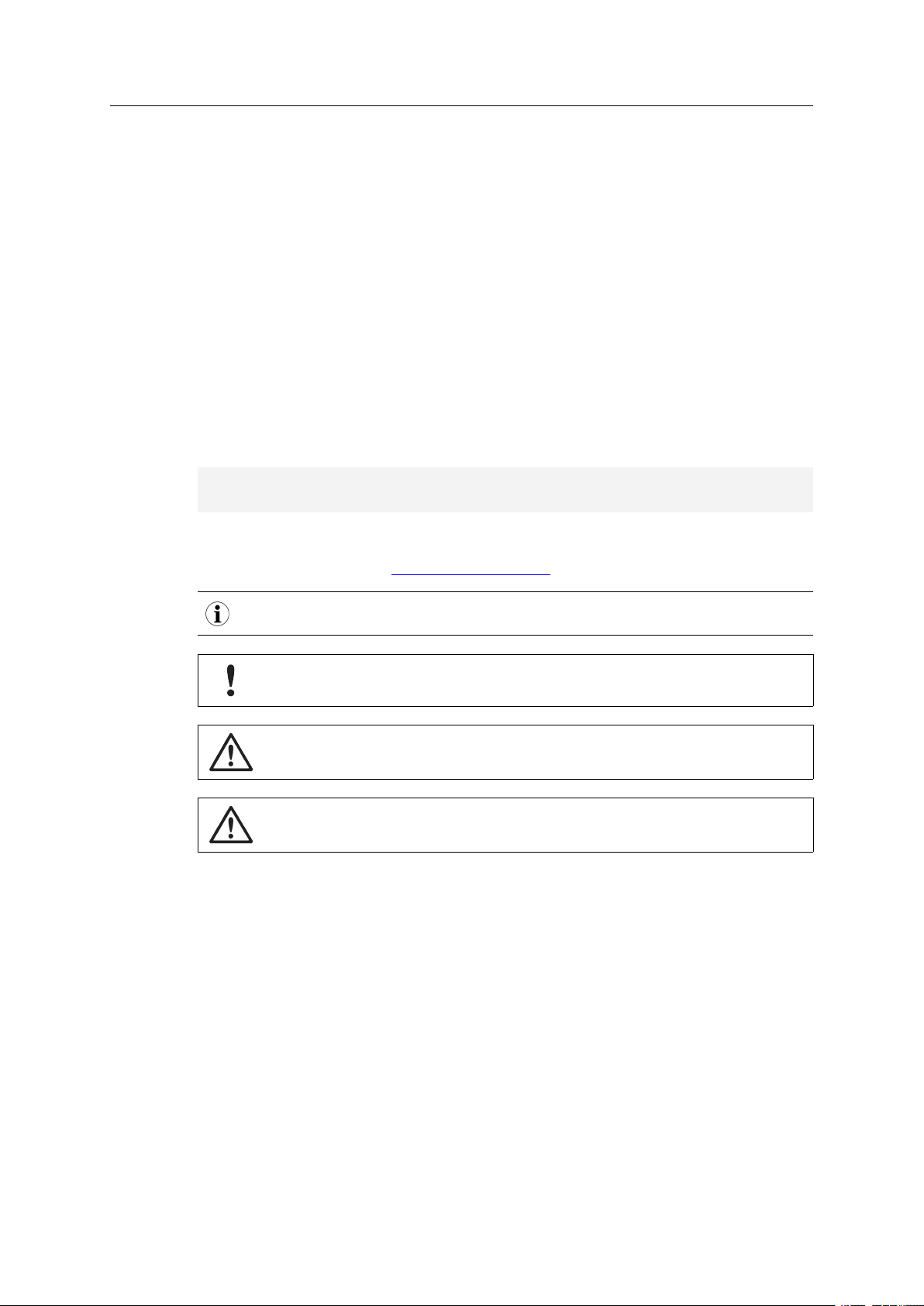
4.1 Module
The modules in the 30-series and the 40-series share physical characteristics, like dimensions,
outline, connectors, LED indicators, mounting parts etc. They are also available as modules
without housing.
Fig. 1 Anybus CompactCom M30/M40
4.2 Chip
The chip (C30/C40) versions of the Anybus CompactCom differ completely when it comes to
physical dimensions.
There is no way to migrate a chip solution from the 30-series to the 40-series
without a major hardware update.
Migrating from Anybus®CompactCom™30 to Anybus®CompactCom™40 Design Guide SCM-1202-043 1.1
Page 13
Hardware Compatibility 11 (38)
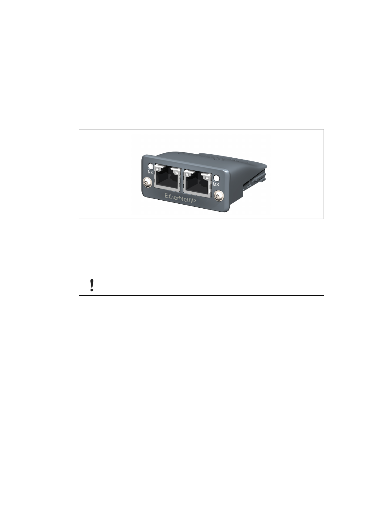
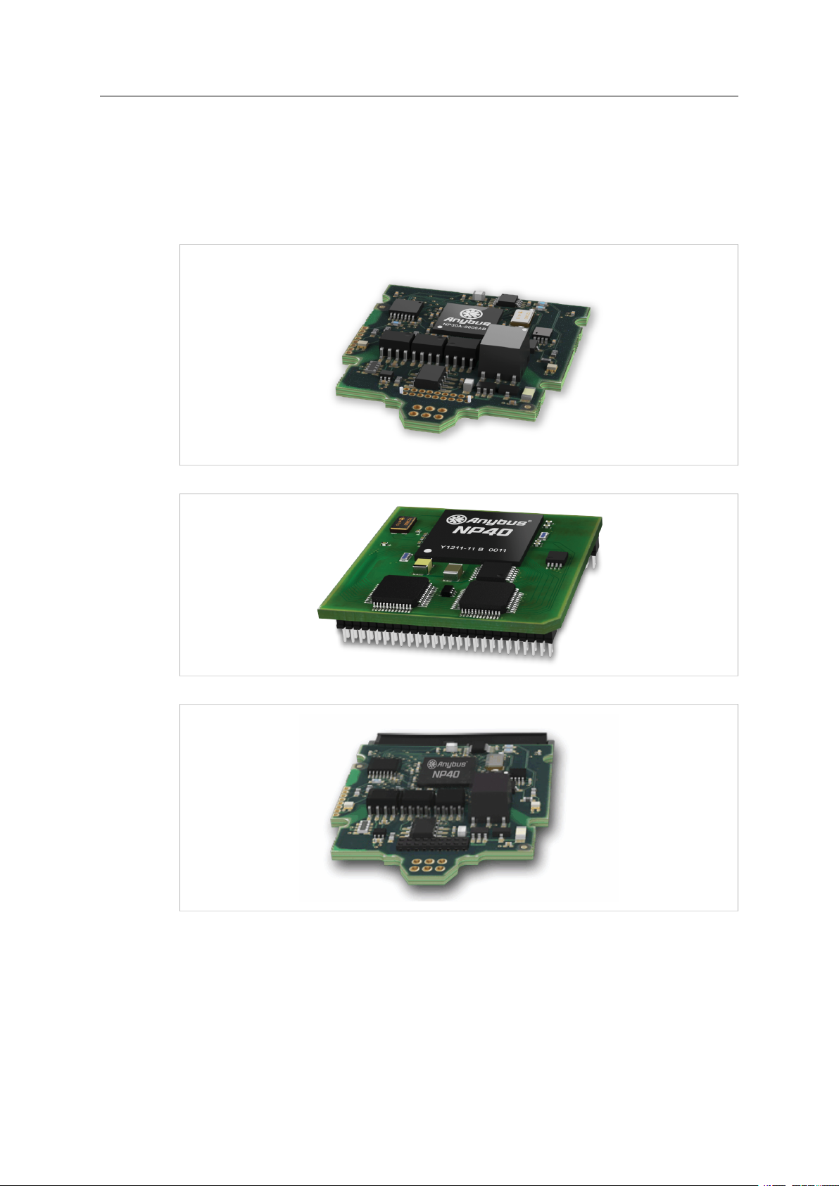
4.3 Brick
The Anybus CompactCom B40-1 does not share dimensions with the Anybus CompactCom
B30. The B40-1 is thus not suitable for migration. However HMS Industrial Networks AB has developed a separate brick version in the 40-series, that can be used for migration. This product,
B40-2, shares dimensions etc. with the B30. Please contact HMS Industrial Networks AB for
more information on the Anybus CompactCom B40-2.
Fig. 2 Anybus CompactCom B30
Fig. 3 Anybus CompactCom B40–1 (not for migration)
Fig. 4 Anybus CompactCom B40–2
Migrating from Anybus
®
CompactCom™30 to Anybus®CompactCom™40 Design Guide SCM-1202-043 1.1
Page 14

Hardware Compatibility 12 (38)
25
50
1
26
MD1A1A3A5A7A9A11
A13D6D4D2D0
VDD
VSS
OM1CEIRQ
RESET
GOP0
GIP0
LED2B
LED1B
Tx/OM3
MI1
VSS
VSS
A0A2A4A6A8
A10
A12
D7D5D3
D1
VDD
VSS
OM0
OM2
R/W
OE
GOP1
GIP1
LED2A
LED1A
Rx
MI0
MD0
4.4 Host Application Interface
Fig. 5
Some signals in the host application interface have modified functionality and/or functions which
must be checked for compatibility. See the following sections.
4.4.1 Tx/OM3
This pin is Tx only in the 30-series. It is tri-stated during power up, and driven by the Anybus
CompactCom UART after initialization. In the 40-series this pin is used as a fourth operating
mode setting pin (OM3). During startup after releasing the reset, this pin is read to determine
the operating mode to use. The pin is then changed to a Tx output.
In the 40-series, this pin has a built-in weak pull-up. If this pin, on a 30-series module or brick is
unconnected, pulled high, or connected to a high-Z digital input on the host processor, it will be
compatible with the 40-series. An external pull-up is recommended, but not required.
If this pin is pulled low by the host during startup, the 40-series module or brick will
not enter the expected operating mode.
Related Information: Anybus CompactCom M40 Hardware Design Guide (HMSI-216-126), Section “Application Connector Pin Overview”
4.4.2 Module Identification (MI[0..1])
These pins are used by the host application (i.e your product) to identify what type of Anybus
CompactCom that is mounted. The identification differs between the 30-series and the 40series.
If your software use this identification you need to handle the new identification value.
MI1 MI0 Module Type
LOW LOW Active Anybus CompactCom 30
HIGH LOW Active Anybus CompactCom 40
MI[0..1] shall only be sampled by the application during the time period from power up to the
end of SETUP state. The pins are low at power up and before reset release.
Related Information: Anybus CompactCom M40 Hardware Design Guide (HMSI-216-126), Section “Settings/Sync”.
Migrating from Anybus®CompactCom™30 to Anybus®CompactCom™40 Design Guide SCM-1202-043 1.1
Page 15

Hardware Compatibility 13 (38)
4.4.3 GIP[0..1]/LED3[A..B]
These pins are tri-stated inputs by default in the 30-series. In the 40-series, these pins are tristated until the state NW_INIT. After that they become open-drain, active low LED outputs (LED3A/LED3B).
No modification of the hardware is needed, if your current design has
• tied these pins to GND
• pulled up the pins
• pulled down the pins
• left the pins unconnected
However, if the application drive the pins high, a short circuit will occur.
If you connect the pins to LEDs, a pull-up is required.
In the 40-series, there is a possibility to set the GIP[0..1] and GOP[0..1] in high impedance state
(tri-state) by using attribute #16 (GPIO configuration) in the Anybus object (01h). I.e. if it is not
possible to change the host application hardware, this attribute can be configured for high impedance state of GIP and GOP before leaving NW_INIT state.
Related Information: Anybus CompactCom M40 Hardware Design Guide (HMSI-216-126), Section “LED Interface/D8-D15 (Data Bus)”
4.4.4 GOP[0..1]/LED4[A..B]
These pins are outputs (high state) by default in the 30-series. In the 40-series, these pins are
tri-stated until the state NW_INIT, and after that they become push-pull, active low LED outputs
(LED4A/LED4B).
This change should not affect your product.
Related Information: Anybus CompactCom M40 Hardware Design Guide (HMSI-216-126), Section 3.2.3, LED Interface/D8-D15 (Data Bus)
4.4.5 Address Pins A[11..13]
The address pins 11, 12, and 13 are ignored by the 30-series. These pins must be high when
accessing the 40-series module in backwards compatible 8-bit parallel mode. If you have left
these pins unconnected or connected to GND, you need to make a hardware modification to tie
them high.
4.4.6 Max Input Signal Level (VIH)
The max input signal level for the 30-series is specified as VIH=VDD+0,2 V, and for the 40-series
as V
=3.45 V. Make sure that you do not exceed 3.45V for a logic high level.
IH
Migrating from Anybus®CompactCom™30 to Anybus®CompactCom™40 Design Guide SCM-1202-043 1.1
Page 16

General Software 14 (38)
5 General Software
5.1 Extended Memory Areas
The memory areas have been extended in the 40-series, and it is now possible to access larger
sizes of process data (up to 4096 bytes instead of former maximum 256 bytes) and message
data (up to 1524 bytes instead of former maximum 255 bytes). The 30-series has reserved
memory ranges that the application should not use. The 40-series implements new functionality
in some of these memory areas.
To use the extended memory areas you need to implement a new communication protocol which
is not part of this document.
Memory areas not supported by the specific network cannot be used. Make sure you do not access these areas, e.g. for doing read/write memory tests.
Related Information: Anybus CompactCom 40 Software Design Guide (HMSI-216-125), Section “Memory Map”
5.2 Faster Ping-Pong Protocol
The ping-pong protocol (the protocol used in the 30-series) is faster in the 40-series. A 30-series module typically responds to a “ping” within 10-100µs. The 40-series typically responds to a
“ping” within 2µs.
Interrupt-driven applications (parallel operating mode) may see increased CPU load due to the
increased speed.
5.3 Requests from CompactCom to Host Application During Startup
All requests to software objects in the host application must be handled and responded to (even
if the object does not exist). This applies for both the 30-series and the 40-series. The 40-series
introduces additional objects for new functionality.
There may also be additional commands in existing objects added to the 40-series that must be
responded to (even if it is not supported).
If your implementation already responds to all commands it cannot process, which is the expected behavior, you do not need to change anything.
5.4 Anybus Object (01h)
Attribute 30-series 40-series Change/Action/Comment
#1, Module Type 0401h 0403h Make sure the host application accepts the
#15, Auxiliary Bit Available Removed It is not possible to turn off the “Changed Data
#16, GPIO
Configuration
Default: General
input and output
pins
Default: LED3
and LED4
outputs
new module type value for the 40-series.
Indication” in the 40-series. Also see “Control
Register CTRL_AUX-bit” and “Status Register STAT_AUX-bit” below.
See also ..
• GIP[0..1]/LED3[A..B], p. 13
• GOP[0..1]/LED4[A..B], p. 13
Migrating from Anybus
®
CompactCom™30 to Anybus®CompactCom™40 Design Guide SCM-1202-043 1.1
Page 17

General Software 15 (38)
5.5 Control Register CTRL_AUX-bit
30-series The CTRL_AUX bit in the control register indicates to the Anybus CompactCom if the
process data in the current telegram has changed compared to the previous one.
40-series The value of the CTRL_AUX bit is always ignored. Process data is always accepted.
All released Anybus CompactCom 30 example drivers from HMS comply with this difference.
Related Information: Anybus CompactCom 40 Software Design Guide (HMSI-216-125), section
“Control Register”.
5.6 Status Register STAT_AUX-bit
30-series The STAT_AUX bit in the status register indicates if the output process data in the current
telegram has changed compared to the previous one. This functionality must be enabled
in the Anybus object (01h), Attribute #15. By default, the STAT_AUX bit functionality is
disabled.
40-series The STAT_AUX bit indicates updated output process data (not necessarily changed data)
from the network compared to the previous telegram. The functionality is always enabled.
All released Anybus CompactCom 30 example drivers from HMS comply with this difference.
Related Information: Anybus CompactCom 40 Software Design Guide (HMSI-216-125), section
“Status Register”.
5.7 Control Register CTRL_R-bit
30-series The application may change this bit at any time.
40-series For the 8-bit parallel operating mode, the bit is only allowed to transition from 1 to 0 when
the STAT_M-bit is set in the status register. When using the serial operating modes, it is
also allowed to transition from 1 to 0 in the telegram immediately after the finalizing empty
fragment.
All released CompactCom 30 example drivers from HMS comply with this difference.
Related Information: Anybus CompactCom 40 Software Design Guide (HMSI-216-125), section
“Control Register”.
5.8 Modifications of Status Register, Process Data Read Area, and Message Data Read Area
In the 40-series, the Status Register, the Process Data Read Area, and the Message Data Read
Area are write protected in hardware (parallel interface). If the software for some reason writes
to any of those areas, a change is needed.
All released Anybus CompactCom 30 example drivers from HMS comply with this difference.
Migrating from Anybus®CompactCom™30 to Anybus®CompactCom™40 Design Guide SCM-1202-043 1.1
Page 18

Network Specific — BACnet/IP 16 (38)
6 Network Specific — BACnet/IP
6.1 Network Configuration Object (04h)
The instances in the Network Configuration Object have been rearranged for the Ethernet
based modules for consistency. Network specific instances are moved to instance number 20
and onwards. This is done to increase the number of instances in the section that is not network
specific.
If the host application is using any of the parameters below, the software must be updated to
use the new instance numbers.
Parameter Name 30-series Instance # 40-series Instance #
Device Instance 3 20
UDP Port 4 21
Process Active Timeout 5 22
IP Address 6 3
Subnet Mask
Gateway Address 8 5
DHCP Enable 9 6
Comm 1 Settings 10 7
Comm 2 Settings 11 8
DNS1 12 9
DNS2 13 10
Host Name 14 11
Domain Name 15 12
SMTP Server 16 13
SMTP User 17 14
SMTP Password 18 15
Foreign Device Registration IP 19 23
Foreign Device Registration UDP Port 20 24
Foreign Device Registration Time to Live Value 21 25
7 4
6.2 Reduced Network Resources Due to Memory Constraints
The Anybus CompactCom 40 BACnet/IP will have reduced network resources compared to the
AnybusCompactCom 30 due to memory constraints.
Network Resource 30-series 40-series
Maximum size of BACnet NPDU 1476 1024
Maximum number of active server requests 10 5
Number of supported COV server subscriptions 60 60
Maximum number of Network Configuration object recipients supported
Number of client requests 120 78
Number of supported Network Configuration
events
Maximum size of APDU service payload with segmentation included
Number of BACnet objects (advanced mode ) 6120 768
Number of BAPL DeviceAddressBindings supported 18
60 18
256 64
32 kB 5 kB
60 18
Migrating from Anybus
®
CompactCom™30 to Anybus®CompactCom™40 Design Guide SCM-1202-043 1.1
Page 19

Network Specific — CC-Link 17 (38)
7 Network Specific — CC-Link
7.1 Network CC-Link Object (08h)
The specific CC-Link mapping commands: Map_ADI_Specified_Write_Area, Map_ADI_Specified_Read_Area have been removed. With these two previously used commands it was possible to freely specify the location of the mapped data in the CC-Link address map; this is not
possible anymore.
The mapping is now handled with the commands: Map_ADI_Write_Area, Map_ADI_Read_
Area or Map_ADI_Write_Ext_Area and Map_ADI_Read_Ext_Area. The location of the mapped
data in the CC-Link address map can now only be managed by using these commands in conjunction with the chronological order the commands are sent.
See “Anybus CompactCom 40 CC-Link Network Guide” for the new Process Data mapping
scheme details.
7.2 Network Object (03h)
7.2.1 Process Data
A new default Process Data mapping scheme has been implemented in the 40-series. Data
type BOOL is now mapped to the Word-area. In the 40-series, use the new BITx data types instead to map the data to the Bit-area.
All bit data must be mapped before all other data types for the data to be mapped to the Bitarea. If mapping bit data after having mapped other “non-bit-data” the data will be mapped to
the Word-area.
The change was made to get a more logical and faster mapping.
You need to make sure the process data is mapped according to the above in the host
application.
7.3 Diagnostic Object (02h)
To use the Diagnostic Events in conjunction with the automatic System Area Handler (CC-Link
Host Object (F7h), Attribute #5, System Area Handler) in the Anybus CompactCom 40 CC-Link,
there is one modification required. The application is now required to use the Diagnostic Events
with the severity representing Latching Events or handle the system area completely in the application. For details on Diagnostic Event with latching severity, see the “Anybus CompactCom
40 Software Design Guide”, Diagnostic Object.
If the Diagnostic Event created is not of the latching severity, the system area will not work according the CC-Link specification.
If the automatic System Area Handler functionality is used previously, add the use of Diagnostic
Events with a latching event severity or let the host application handle the system area
completely.
Migrating from Anybus®CompactCom™30 to Anybus®CompactCom™40 Design Guide SCM-1202-043 1.1
Page 20

Network Specific — DeviceNet 18 (38)
8 Network Specific — DeviceNet
8.1 DeviceNet Host Object (FCh)
Attribute 30-series 40-series Change/Action/Comment
#2, Device Type Default: 0000h Default: 002Bh If the attribute is implemented in the host ap-
#3, Product Code Default: 0062h Default: 003Fh If the attribute is implemented in the host ap-
#6, Product Name Default: “Any-
bus-CC
DeviceNet”
Default: “CompactCom 40 DeviceNet(TM)”
plication, it overrides the default value and
there is no difference between the 30-series
and the 40-series.
If the attribute is not implemented, the default
value is used.
plication, it overrides the default value and
there is no difference between the 30-series
and the 40-series.
If the attribute is not implemented, the default
value is used.
If the attribute is implemented in the host application, it overrides the default value and
there is no difference between the 30-series
and the 40-series.
If the attribute is not implemented, the default
value is used.
8.2 EDS file (Electronic Datasheet file used by configuration tool)
8.2.1 Keywords
The following keywords must be updated when migrating.
Keyword Comments
ProdType Must match attribute #2 (Device Type) in the Device-
ProdCode Must match attribute #3 (Product Code) in the Device-
ProdName Must match attribute #6 (Product Name) in the Devi-
MajRev Must match the major revision of the product.
Net Host Object (FCh).
Net Host Object (FCh).
ceNet Host Object (FCh).
Migrating from Anybus
®
CompactCom™30 to Anybus®CompactCom™40 Design Guide SCM-1202-043 1.1
Page 21

Network Specific — EtherCAT 19 (38)
9 Network Specific — EtherCAT
9.1 Network Configuration Object (04h)
The instance number for the Device ID instance has changed from number 3 (30-series) to
number 1 (40-series).
9.2 EtherCAT Object (F5h)
Attribute 30-series 40-series Change/Action/Comment
#2, Product Code Default: 0000
#6, Manufacturer Device Name
0034h
Default: “Anybus-CC
EtherCAT”
Default: 0000
0036h
Default: “CompactCom 40
EtherCAT”
If the attribute is implemented in the host application, it overrides the default value and
there is no difference between the 30-series
and the 40-series.
If the attribute is not implemented, the default
value is used.
If the attribute is implemented in the host application, it overrides the default value and
there is no difference between the 30-series
and the 40-series.
If the attribute is not implemented, the default
value is used.
9.3 ESI-file (Configuration file used by engineering tool)
When migrating from the 30-series to the 40-series, a new, updated ESI-file is needed. To help
you, there is an ESI-file Generator available from HMS Industrial Networks AB, see below.
9.3.1 ESI-file Generator
An ESI-file generator is available on the HMS Industrial Networks AB website. The generator
will create an up to date ESI file fitted for the specific design. The ESI generator works for both
the 30-series and the 40-series.
The generator can be downloaded from www.anybus.com/starterkit40.
Migrating from Anybus®CompactCom™30 to Anybus®CompactCom™40 Design Guide SCM-1202-043 1.1
Page 22

Network Specific — EtherCAT 20 (38)
9.3.2 Keywords
The ESI-file generator is up to date with the following differences between the 30-series and the
40-series.
The Product Code, Revision Number and Product Name must be updated to reflect the current
module. Note: These values can be changed via the EtherCATobject (F5h) and the ESI-file values must match the EtherCAT object values.
<Type ProductCode="#x00000036" RevisionNo="#x00020001">
CompactCom 40 EtherCAT</Type>
The EtherCATstate transition timeouts must be present in the ESI-file per the latest specification. Note: These timeout values can be change via the EtherCAT object (F5h) and the ESI-file
values must match the EtherCAT object values.
<StateMachine>
<Timeout>
<PreopTimeout>1000</PreopTimeout>
<SafeopOpTimeout>5000</SafeopOpTimeout>
<BackToInitTimeout>1000</BackToInitTimeout>
<BackToSafeopTimeout>200</BackToSafeopTimeout>
<Timeout>
</StateMachine>
The sync manager start addresses have been changed in the 40-series, and the sync manager
sizes are now configurable in the EtherCATconfiguration tool.
<Sm MinSize="34" MaxSize="1486" DefaultSize="276" StartAddress="#x4000"
ControlByte="#x26" Enable="1">MBoxOut</Sm>
<Sm MinSize="34" MaxSize="1486" DefaultSize="276" StartAddress="#x4800"
ControlByte="#x22" Enable="1">MBoxIn</Sm>
<Sm StartAddress="#x2800" ControlByte="#x20" Enable="1">Inputs</Sm>
The 40-series supports File over EtherCAT (FoE) and this must be reflected in the ESI-file. If
FoE is disabled in the EtherCAT host object, this keyword must be removed from the ESI-file.
<FoE/>
Since the 40-series is using the HMS slave controller, the EEPROM byte size and the SII configuration data must be changed according to the following settings.
<ByteSize>384</ByteSize>
<ConfigData>80360046F4010000000000000000</ConfigData>
The 40-series supports the boot strap state, and requires the following keyword.
<BootStrap>0040000400480004</BootStrap>
Migrating from Anybus®CompactCom™30 to Anybus®CompactCom™40 Design Guide SCM-1202-043 1.1
Page 23

Network Specific — EtherNet/IP 21 (38)
10 Network Specific — EtherNet/IP
10.1 Network Object (03h)
Attribute #1, Network
Type
Value Network Type Anybus CompactCom Product
0085h EtherNet/IP, No DLR 30-series 1-port
009Ch EtherNet/IP, Announce Based DLR 30-series 2-port
009Bh EtherNet/IP, Beacon Based DLR 30-series and 40-series
The 30-series module is available in two network type versions, either with
“Beacon based DLR” (Highest performance) or with “Announce based DLR”
which both are Ethernet redundancy protocols. The 40-series is only available
with “Beacon based DLR”. The network type value differs between the versions.
10.2 EtherNet/IP Host Object (F8h)
Attribute Default Anybus CompactCom
#2, Device
Type
#3, Product
Code
#6, Product
Name
Attribute
#27, Producing Instance
Map
Attribute
#28, Consuming Instance Map
0000h 30-series, EtherNet/IP,
0000h 30-series, EtherNet/IP,
002Bh 30-series, EtherNet/IP,
002Bh 40-series, EtherNet/IP,
0063h 30-series, EtherNet/IP,
002Eh 30-series, EtherNet/IP,
0036h 30-series, EtherNet/IP,
0037h 40-series, EtherNet/IP,
Anybus-CC EtherNet/IP 30-series, EtherNet/IP,
CompactCom EtherNet/
IP(TM) 2P
Anybus-CC EIP (2-Port)
BB DLR
Anybus CompactCom 40
EtherNet/IP(TM)
See comment Attribute removed in the 40-series
See comment Attribute removed in the 40-series
Product
No DLR
Announce Based DLR
Beacon Based DLR
Beacon Based DLR
No DLR
Announce Based DLR
Beacon Based DLR
Beacon Based DLR
No DLR
30-series, EtherNet/IP,
Announce Based DLR
30-series, EtherNet/IP,
Beacon Based DLR
40-series, EtherNet/IP,
Beacon Based DLR
Comment
If the attribute is implemented in the
host application, it overrides the default value and there is no difference
between the 30-series and the 40series.
If the attribute is not implemented,
the default value is used.
If the attribute is implemented in the
host application, it overrides the default value and there is no difference
between the 30-series and the 40series.
If the attribute is not implemented,
the default value is used.
If the attribute is implemented in the
host application, it overrides the default value and there is no difference
between the 30-series and the 40series.
If the attribute is not implemented,
the default value is used.
(only available in the 30-series EtherNet/IP Beacon Based DLR). The
CompactCom will never request this
attribute. Replaced by the functionality in the Assembly Mapping Object
(EBh).
If this attribute is used, the Assembly
Mapping object must be implemented
instead.
(only available in the 30-series EtherNet/IP Beacon Based DLR). The
CompactCom will never request this
attribute. Replaced by the functionality in the Assembly Mapping Object
(EBh).
If this attribute is used, the Assembly
Mapping object must be implemented
instead.
Migrating from Anybus
®
CompactCom™30 to Anybus®CompactCom™40 Design Guide SCM-1202-043 1.1
Page 24

Network Specific — EtherNet/IP 22 (38)
10.2.1 EtherNet/IP functionality
Max Message
Connections
EtherNet/IP
Encapsulation
Sessions
The maximum number of simultaneous Class 3 connections are 16 in the 30series and 6 in the 40-series.
No change is needed in the host application.
The maximum number of simultaneous encapsulation sessions are 48 in the 30series and 15 in the 40-series.
No change is needed in the host application.
10.3 EDS file (Electronic Datasheet file used by configuration tool)
10.3.1 EDS file Generator Tool
An EDS-generator for automatic EDS-file generation up to date with the differences below. The
EDS-generator only works with the 40-series, version 1.30 and later.
The generator can be downloaded from www.anybus.com/starterkit40: .
10.3.2 Keywords
The following keywords differs between the 30-series and the 40-series. The EDS generator reflects this change.
Keyword Comments
Capacity->MaxCIPConnections Removed in 40-series – replaced by: MaxMsgCon-
Capacity->MaxMsgConnections New keyword in the 40-series, Value: 6
Capacity->MaxIOConnections New keyword in the 40-series, Value: 4
nections and MaxIOConnections (see below)
Migrating from Anybus
®
CompactCom™30 to Anybus®CompactCom™40 Design Guide SCM-1202-043 1.1
Page 25

Network Specific — Modbus-TCP 23 (38)
11 Network Specific — Modbus-TCP
11.1 Modbus Registers
Rearrangements have been made in the Modbus register map, because process data sizes
have been increased to 1536 bytes in each direction. An existing PLC configuration need to be
changed to use the new addresses. No difference on the application side.
Contents 30-series Modbus Address 40-series Modbus Address
Holding Registers (4x)
Read Process Data 0000h-00FFh 0000h-02FFh
Write Process Data 0100h-01FFh 0800h-0AFFh
Process Active Timeout 0203h 1003h
Enter/Exit Idle Mode 0204h 1004h
ADI Number 1 0210h-021Fh 1010h-101Fh
ADI Number 2 0220h-022Fh 1020h-102Fh
ADI Number 3839 FFF0h-FFFFh
Input Registers (3x)
Write Process Data 0000h-00FFh 0000h-02FFh
Diagnostic Event Count 0100h 0800h
Diagnostic Event #1 0101h 0801h
Diagnostic Event #2 0102h 0802h
Diagnostic Event #3 0103h 0803h
Diagnostic Event #4 0104h 0804h
Diagnostic Event #5 0105h 0805h
Diagnostic Event #6 0106h 0806h
Coils (0x)
Read Process Data 0000h-0FFFh 0000h-2FFFh
Discrete Inputs (1x)
Write Process Data 0000h-0FFFh 0000h-2FFFh
11.2 BOOL arrays
Process data mapped BOOL arrays are not compressed to bit-fields on the network in the 40series, but handled as a normal 8-bit datatype. To create bit-arrays in the 40-series, use the
new datatypes BITx instead.
Migrating from Anybus®CompactCom™30 to Anybus®CompactCom™40 Design Guide SCM-1202-043 1.1
Page 26

Network Specific — Modbus-TCP 24 (38)
11.3 Network Configuration Object (04h)
The instances in the Network Configuration Object have been rearranged for the Ethernet
based modules for consistency. Network specific instances are moved to instance number 20
and onwards. This is done to increase the number of instances in the section that is not network
specific.
If the host application is using any of the parameters below, the software must be updated to
use the new instance numbers.
Parameter Name 30-series Instance # 40-series Instance #
Modbus Connection Timeout 9 20
Process Active Timeout 10 21
DNS1 11 9
DNS2 12 10
Host Name 13 11
Domain Name 14 12
SMTP Server 15 13
SMTP User 16 14
SMTP Password 17 15
Word Order 18 22
11.4 Modbus Host Object (FAh)
Attribute 30-series 40-series Change/Action/Comment
#2, Product Code Default: “Any-
#11,Modbus read/
write registers command offset
bus-CC ModbusTCP (2-Port)”
- -
Default: “Anybus
CompactCom 40
Modbus TCP”
11.5 Ethernet Host Object (F9h)
Attribute 30-series 40-series Change/Action/Comment
#4, Enable ModbusTCP
Available Removed Attribute removed in the 40-series. The Com-
11.6 Process data
If the attribute is implemented in the host application, it overrides the default value and
there is no difference between the 30-series
and the 40-series.
If the attribute is not implemented, the default
value is used.
In the 30-series, this register address offset is
only applied when accessing holding registers with the command Read/Write Multiple
registers (23).
The 40-series applies this register offset to all
holding register access, i.e. commands 3, 6,
16 and 23.
pactCom will never request this attribute.
Nothing needs to be changed in the host
application.
In the 30-series modules, writing to the ADI register area would only result in a Set_Attribute
command to the application (Application Data Object (FEh)) if the ADI was not mapped to read
process data. For the 40-series, all register writes to the ADI area also results in a corresponding Set_Attribute command to the host application (Application Data Object (FEh)), as well as
updating of the process data.
Migrating from Anybus®CompactCom™30 to Anybus®CompactCom™40 Design Guide SCM-1202-043 1.1
Page 27

Network Specific — PROFIBUS 25 (38)
12 Network Specific — PROFIBUS
12.1 Additional Diagnostic Object (05h)
Object removed in the 40-series. To create diagnostics, use Diagnostic Object (02h).
Another option is to use the PROFIBUS DP-V0 Diagnostic Object (10h) where diagnostics can
be sent transparently from the host application to the network.
If you use the Additional Diagnostic Object you need to update your software implementation.
12.2 Network PROFIBUS DP-V1 Object (0Bh)
Object removed in the 40-series, i.e. commands Map_ADI_Specified_Write_Area and Map_
ADI_Specified_Read_Area are not supported.
12.3 PROFIBUS DP-V1 Object (FDh)
Attribute 30-series 40-series Change/Action/Comment
#1, PNO Ident
Number
#2, Parameterization
Data
#5, Size of Identifier
Related Diagnostics
#6, Buffer Mode Available Removed Attribute removed in the 40-series. The Any-
#7, Alarm Settings Available Removed Attribute removed in the 40-series. The Any-
#16, I&M Version Available Removed Attribute removed in the 40-series. The Any-
#17, I&M Supported Available Removed Attribute removed in the 40-series. The Any-
#19, Check Config
Behavior
1811h 1815h If the attribute is implemented in the host ap-
plication, it overrides the default value and
there is no difference between the 30-series
and the 40-series.
If the attribute is not implemented, the default
value is used.
See Comment In the first 10 bytes, only the Parameter Struct
bit (bit 3) is copied to this attribute in the 40series. All other bits are set to 0.
In the 30-series all information in the first 10
bytes were copied.
Available Removed Attribute removed in the 40-series. The Any-
bus CompactCom will never request this
attribute.
Nothing needs to be changed.
bus CompactCom will never request this attribute. No buffer modes needed in the 40series since maximum sizes for all buffers are
supported.
Nothing needs to be changed.
bus CompactCom will never request this attribute. Only Diagnostic Alarms supported.
bus CompactCom will never request this attribute. The host application cannot influence
the I&M version implemented by the Anybus
CompactCom.
bus CompactCom will never request this attribute. The host application cannot influence
the I&M version supported by the Anybus
CompactCom.
Available Removed Attribute removed in the 40-series. The Any-
bus CompactCom will never request this
attribute.
The 40-series depends on CheckCfgMode
(often configurable in the PROFIBUS master)
in default mode. Either the expected and actual configuration must match exactly or can
differ as long as the expected input and output sizes are equal or larger than the actual
sizes.
Migrating from Anybus
®
CompactCom™30 to Anybus®CompactCom™40 Design Guide SCM-1202-043 1.1
Page 28

Network Specific — PROFIBUS 26 (38)
12.4 Network Configuration Object (04h)
The following attributes are removed in the 40–series. The Anybus CompactCom will never request these attributes. It is only possible to set these values via the network (I&M1-4) – end user
configuration.
• Instance #3, Function Tag
• Instance #4, Location Tag
• Instance #5, Installation Date
• Instance #6, Description
12.5 GSD file (PROFIBUS configuration file used by engineering tool)
Implementation Type If the keyword “Implementation Type” is present in the GSD-file (optional
keyword), the value for the 30-series shall be “NP30” and the value for the 40series shall be “NP40”.
Length Related
Keywords
The following keywords are possible to set to maximum values if neeed in the 40series. In the 30-series the maximum lengths were dependent of the buffer mode
setting.
• Max_Input_Len
• Max_Output_Len
• Max_Data_Len
• Max_User_Prm_Data_Len
• Max_Diag_Data_Len
Migrating from Anybus
®
CompactCom™30 to Anybus®CompactCom™40 Design Guide SCM-1202-043 1.1
Page 29

Network Specific — PROFINET 27 (38)
13 Network Specific — PROFINET
Related Information:
Anybus CompactCom 40 PROFINET IRT Network Guide, HMSI-27-226
Network Interface Appendix, Anybus CompactCom 30, PROFINET IO 2-Port, HMSI-168-49
13.1 Network Object (03h)
Attribute Default Anybus CompactCom Product Comment
#1, Network
Type
#2, Network
Type String
0084h 30-series, PROFINET IO 1-Port The 30-series module is a PROFI-
0096h 30-series, PROFINET IO 2-Port
0089h 40-series, PROFINET IRT
“PROFINET
IO”
“PROFINET
IO 2-Port”
“PROFINET
IRT”
30-series, PROFINET IO 1-Port The 30-series module is a PROFI-
30-series, PROFINET IO 2-Port
40-series, PROFINET IRT
NET RT module without IRT capabilities. The 40-series module has
PROFINET IRT capabilities. The Network Type value differs between the
different CompactCom PROFINET
versions.
NET RT module without IRT capabilities. The 40-series module has
PROFINET IRT capabilities. The Network Type value differs between the
different CompactCom PROFINET
versions.
Migrating from Anybus
®
CompactCom™30 to Anybus®CompactCom™40 Design Guide SCM-1202-043 1.1
Page 30

Network Specific — PROFINET 28 (38)
13.2 PROFINET IO Object (F6h)
Attribute Default Anybus CompactCom Product Comment
#1, Device
ID
#3, Station
Type
#8, I&M Order ID
#19, System
Description
0007h 30-series, PROFINET IO 1-Port The Device ID controls how your
0009h 30-series, PROFINET IO 2-Port
0010h 40-series, PROFINET IRT
“ABCC-PRT” 30-series, PROFINET IO 1-Port The Station Type defines the name
“ABCC-PRT
(2-Port)”
“ABCC40PIR”
“ABCC-PRT” 30-series, PROFINET IO 1-Port If the attribute is implemented in the
“ABCC-PRT
(2-Port)”
“ABCC40PIR”
“HMS Industrial Networks Anybus CompactCom”
“Anybus
CompactCom PROFINET IO 2Port”
“HMS Industrial Networks Anybus-CompactCom 40”
30-series, PROFINET IO 2-Port
40-series, PROFINET IRT
30-series, PROFINET IO 2-Port
40-series, PROFINET IRT
30-series, PROFINET IO 1-Port If the attribute is implemented in the
30-series, PROFINET IO 2-Port
40-series, PROFINET IRT
product identifies itself on the PROFINET network.
If the attribute is implemented in the
host application, it overrides the default value and there is no difference
between the 30-series and the 40series.
If the attribute is not implemented,
the default value differs between the
different CompactCom PROFINET
types.
your product uses to identify itself on
the PROFINET network.
If the attribute is implemented in the
host application, it overrides the default value and there is no difference
between the 30-series and the 40series.
If the attribute is not implemented,
the default value differs between the
different CompactCom PROFINET
types.
host application, it overrides the default value and there is no difference
between the 30-series and the 40series.
If the attribute is not implemented,
the default value differs between the
different Anybus CompactCom PROFINET types.
host application, it overrides the default value and there is no difference
between the 30-series and the 40series.
If the attribute is not implemented,
the default value differs between the
different Anybus CompactCom PROFINET types.
Migrating from Anybus
®
CompactCom™30 to Anybus®CompactCom™40 Design Guide SCM-1202-043 1.1
Page 31

Network Specific — PROFINET 29 (38)
Attribute 30-series 40-series Change/Action/Comment
#7, Record Data
Mode
#13, I&M Profile ID Used for all APIs Only used for
#14, I&M Profile Specific Type
#15, I&M Version Available Removed Attribute removed in the 40-series. The Any-
16, I&M Supported Available Removed Attribute removed in the 40-series. The Any-
#20, Interface
description
#21, Module ID Assignment Mode
#22, System Contact Available Removed Attribute removed in the 40-series. The Any-
#23, PROFIenergy
functionality
See Comment I&M Record data transparent mode (bit 1) is
replaced with the IM_Options command in the
Network PROFINET IO object (0Eh).
If this bit is 0 in the current implementation, no
action is needed
In the 40-series, this attribute is only read for
“non-zero” APIs
submodules belonging to a “non-zero” API (e.
g. PROFIdrive profile). Constant values
(F600h, Generic Device and 0004h, Communication Module) are used for submodules belonging to API 0.
In the 30-series this parameter is used for all
API:s.
Used for all APIs Only used for
“non-zero” APIs
In the 40-series, this attribute is only read for
submodules belonging to a “non-zero API” (e.
g. PROFIdrive profile). Constant values
(F600h, Generic Device and 0004h, Communication Module) are used for submodules belonging to API 0.
In the 30-series this parameter is used for all
API:s.
bus CompactCom will never request this attribute. The host application cannot influence
the I&M implemented by the Anybus
CompactCom.
bus CompactCom will never request this attribute. The host application cannot influence
the I&M supported by the Anybus
CompactCom.
Available Removed Attribute removed in the 40-series. The Any-
bus CompactCom will never request this
attribute.
Available Removed Attribute removed in the 40-series (Incremen-
tal Module Identification removed in the 40series). The Anybus CompactCom will never
request this attribute.
bus CompactCom will never request this attribute. System Contact can now only be
reached from the network via SNMP (sysContact). Also see SNMP MIB-II, p. 33.
Available Removed Attribute removed in the 40-series. The Any-
bus CompactCom will never request this attribute. PROFIenergy is now enabled by the
application having implemented the Energy
Control Object (F0h).
Migrating from Anybus
®
CompactCom™30 to Anybus®CompactCom™40 Design Guide SCM-1202-043 1.1
Page 32

Network Specific — PROFINET 30 (38)
Command 30-series 40-series Change/Action/Comment
Ar_Info_Ind Available Removed Command removed in the 40-series. The Any-
Ar_Offline_Ind Available Removed Command removed in the 40-series. The Any-
Plug_Submodule_
Failed
Get_IM_Record Available Removed Command removed in the 40-series. The Any-
Set_IM_Record Available Removed Command removed in the 40-series. The Any-
Available Removed Command removed in the 40-series. The Any-
bus CompactCom will never use this command in a request. The command is replaced
by the command Expected_Ident_Ind
bus CompactCom will never use this command in a request. The 30-series module
issues this command to indicate to the host
application that the module enters an offline
state. Use Ar_Abort_Ind instead.
bus CompactCom will never use this command in a request.
bus CompactCom will never use this command in a request. It will use the general Get_
Record-command instead (filter on index
AFF0h-AFFFh).
bus CompactCom will never use this command in a request. It will use the general Set_
Record-command instead (filter on index
AFF0h-AFFh).
13.3 PROFINET Additional Diagnostic Object (0Fh)
Object removed in the 40-series. All diagnostics are handled via the standard diagnostic object
(02h), Event code FFh. Only Channel diagnostics can be created.
13.4 Diagnostic Object (02h)
The structure of network specific event information has changed in the create command. Instead of including diagnostic source information such as API, Slot, and Subslot in the data field,
it is extracted from the extended diagnostic fields in the create command. API, Slot, and Subslot
are determined with the help of Slot and ADI given by the extended diagnostic mode.
Process alarms cannot be created in the 40-series.
Migrating from Anybus®CompactCom™30 to Anybus®CompactCom™40 Design Guide SCM-1202-043 1.1
Page 33

Network Specific — PROFINET 31 (38)
13.5 Network Configuration Object (04h)
The instances in the Network Configuration Object have been rearranged for the Ethernet
based modules for consistency. Network specific instances are moved to instance number 20
and onwards. This is done to increase the number of instances in the section that is not network
specific.
If the host application is using any of the parameters below, the software must be updated to
use the new instance numbers.
Parameter Name 30-series Instance # 40-series Instance #
DNS1 8 9
DNS2 9 10
Host Name 10 11
Domain Name 11 12
SMTP Server 12 13
SMTP User 13 14
SMTP Password 14 15
Station Name 15 20
F-Address 20 21
Function Tag 16 Parameter removed
Location Tag 17 Parameter removed
Installation Date 18 Parameter removed
Description 19 Parameter removed
The following instances are removed in the 40-series. They are only possible to set via the
network.
• Instance #16 in 30-series, Function Tag
• Instance #17 in 30-series, Location Tag
• Instance #18 in 30-series, Installation Date
• Instance #19 in 30-series, Description
13.6 Network PROFINET IO Object (0Eh)
Attribute 30-series 40-series Change/Action/Comment
#3, Last OffLineInd
ReasonCode
#9, ProfinetIoStack
Init ErrorCode
-
-
Removed Attribute removed in the 40-series. Since the
Removed Attribute removed in the 40-series.
13.7 I&M4
command Ar_Offline_Ind is removed, this attribute makes no sense.
If the host application is accessing this attribute, it will receive an error response when using the 40-series.
If the host application is accessing this attribute, it will receive an error response when using the 40-series.
I&M4 is removed in the 40-series. Writeable I&M records in GSD must be updated (see GSD
section below).
Migrating from Anybus®CompactCom™30 to Anybus®CompactCom™40 Design Guide SCM-1202-043 1.1
Page 34

Network Specific — PROFINET 32 (38)
1 2
3
4
13.8 LED Indications
Changes has been made regarding the specification of the LED indications. See tables below
for differences.
Fig. 6
13.8.1 Network Status LED (LED1[A..B])
LED State 30-series 40-series Comments
Off Offline Offline - No power- No connection with IO
Green Online (RUN) Online (RUN) Connection with IO controller estab-
Green, 1 flash
Green, 3 flashes
Green, cont. flash Online (STOP)
Red Fatal event Fatal event Major internal error (this indication is
Red, 1 flash
Red, 2 flashes
Red, 3 flashes
-
-
-
-
-
Online (STOP) Connection with IO controller estab-
Identify Flashing 3 times (1Hz) continuously
-
Station Name error Station name not set
IP address error IP address not set
Configuration error Expected Identification differs from
controller
lished, IO controller in Run state
lished, IO controller in STOP state or
IO data bad, IRT synchronization not
finished
to identify slave (DCP_Identify).
Connection with IO controller established, IO controller in STOP state
combined with a red module status
LED)
Real Identification.
Migrating from Anybus
®
CompactCom™30 to Anybus®CompactCom™40 Design Guide SCM-1202-043 1.1
Page 35

Network Specific — PROFINET 33 (38)
13.8.2 Module Status LED (LED2[A..B])
LED State 30-series 40-series Comments
Off Not Initialized Not Initialized No power or Module in SETUP or
Green Normal Operation Normal Operation Module has shifted from the NW_IN-
Green, 1 flash Diagnostic Event Diagnostic Event Diagnostic event(s) present
Green, cont. flash Identify
Red Exception error Exception error Module in state Exception
Fatal Event Fatal Event Major internal error (this indication is
Red, 1 flash Configuration error
Red, 2 flashes IP address error
Red, 3 flashes Station Name Error
Red, 4 flashes Internal error
Alternating Red/
Green
-
-
-
-
-
-
Firmware Update Do NOT power off the module. Turn-
NW_INIT state
IT state
Flashing 1Hz continuously to identify
slave (DCP_Identify).
combined with a red Network Status
LED)
ing the module off during this phase
could cause permanent damage.
13.9 SNMP MIB-II
sysContact, sysLocation and sysName are used to give the product identification in the end
installation.
In the 40-module these variables are only set from the network using SNMP protocol by the end
user.
Due to this, sysContact (PROFINET IO object (F6h), Attribute 22), sysLocation (Network Configuration Object (04h), Attribute 17) and sysName (Network Configuration Object (04h), Attribute 15) are no longer used.
Nothing needs to be updated in your implementation but attribute values will no longer be used.
Migrating from Anybus®CompactCom™30 to Anybus®CompactCom™40 Design Guide SCM-1202-043 1.1
Page 36

Network Specific — PROFINET 34 (38)
Submodule ID:Module ID:
0: Mapped to write PD area
1: Mapped to read PD area
Number of
elements to map
0x00000301
ADI start
element number
ADI number
0x00000004
13.10 ADI Based Configuration
When using the ADI based configuration, the structure of module identifiers and submodule
identifiers are changed in the 40-series to be able to support the re-map functionality.
13.10.1 30-series (2-Port)
DAP V2.0: Module ID: 0x00000011, Submodule ID: 0x00000001
Modules:
Fixed module IDs for different data sizes and data directions
Output 1 byte - Module ID: 0x00000020, Submodule ID: 0x00000000
Output 1 word - Module ID: 0x00000030, Submodule ID: 0x00000000
Output 2 word - Module ID: 0x00000040, Submodule ID: 0x00000000
Output 4 word – Module ID: 0x00000050, Submodule ID: 0x00000000
Input 1 byte – Module ID: 0x00000002, Submodule ID: 0x00000000
Input 1 word – Module ID: 0x00000003, Submodule ID: 0x00000000
Input 2 word - Module ID: 0x00000004, Submodule ID: 0x00000000
Input 4 word – Module ID: 0x00000005, Submodule ID: 0x00000000
One submodule per module
13.10.2 40-series
DAP: Module ID: 0x80010000, Submodule ID: 0x00000001
Modules:
The Module IDs and Submodule IDs are built up according to the figure below.
Fig. 7
Migrating from Anybus
®
CompactCom™30 to Anybus®CompactCom™40 Design Guide SCM-1202-043 1.1
Page 37

Network Specific — PROFINET 35 (38)
13.11 Configuration Mismatch
The 40-series are stricter regarding outputs and more tolerant regarding inputs compared to the
30-series. All outputs are locked if at least one output is missing. The network engineering tool
may use anywhere between 0 and all actual input submodules without error indication.
ABCC40 provides a window for "seamless" adaptation of Real Identification (RI). In ADI based
RI mode through remap, and in advanced mode by blocking in the connect request handling. It
is not ok to adapt RI by rebooting.
For detailed information about how a configuration mismatch is handled in the 30-series, see
Anybus CompactCom 30 PROFINET IO Network Appendix, HMSI-168-74, Section “Configuration Mismatch”.
For detailed information about how a configuration mismatch is handled in the 40-series, see
Anybus CompactCom 40 PROFINET IRT Network Guide, HMSI-27-226, Section “Configuration
Mismatch”.
13.12 Media Redundancy Protocol (MRP)
MRP is supported in the 40-series and cannot be disabled by the host application. You need to
add new keywords in your GSD file, see GSD section below.
13.13 GSD File (PROFINET configuration file used by engineering tool)
13.13.1 GSD Generator Tool
When using the ADI-based configuration, it is possible to use a GSD Generator from HMS
which will generate a basic GSD file (up to date with the above differences) with correct ADI
modules.
The GSD generator only works for the 40-series
The generator can be downloaded from www.anybus.com/starterkit40
Migrating from Anybus®CompactCom™30 to Anybus®CompactCom™40 Design Guide SCM-1202-043 1.1
Page 38

Network Specific — PROFINET 36 (38)
13.13.2 Modifications for Conformance Class B (if you want to disable support for IRT)
The example GSD file, supplied by HMS Industrial Networks AB, is prepared for testing an Anybus CompactCom 40 PROFINET IRT for conformance class C, which includes PROFINET isochronous communication mode (IRT). If the implementation does not need the isochronous
features of the device, the GSD file can be modified to reflect this. The product can then be conformance tested for conformance class B instead. The list below describe the changes needed
in the example GSD file to accomplish this.
If IRT support is removed from the GSD file, it is not possible to use the device in
the middle of an IRT line. It has to be connected to the line using an IRT capable
switch or placed at the end of the line.
1. 1. The value of the ConformanceClass attribute in the <CertificationInfo...> ele-
ment in each DAP must be changed from “C” to “B”:
<CertificationInfo ConformanceClass="B" ApplicationClass=""
NetloadClass="III"/>
2. The value of the SupportedRT_Classes attribute in the <InterfaceSubmoduleItem...
> element in each DAP must be “RT_CLASS_1”. I.e. the “RT_CLASS_2” and “RT_
CLASS_3” values must be removed. Also, remove the keyword
DelayMeasurementSupported.
<InterfaceSubmoduleItem ID=“Interface” SubslotNumber=“32768”
SubmoduleIdentNumber=“0x00000002” SupportedRT_Classes=“RT_CLASS_1”
TextId=“T_ID_INTERFACE ”SupportedProtocols=“SNMP;LLDP”
SupportedMibs=“MIB2” DCP_
HelloSupported=“true” PTP_BoundarySupported=“true” DCP_
BoundarySupported=“true”
3. 3. The elements <RT_Class3Properties ...>, <SynchronisationMode ...>, and
<RT_Class3TimingProperties ...> must be removed from each DAP.
Migrating from Anybus®CompactCom™30 to Anybus®CompactCom™40 Design Guide SCM-1202-043 1.1
Page 39

Network Specific — PROFINET 37 (38)
13.13.3 Keywords
Keyword Comments
GSDML-DeviceProfile version 2.31 for 30-series, 2.32 for 40-series
DeviceIdentity->DeviceID Must be changed to reflect the Device ID you have configured
DeviceAccessPointItem->CheckDeviceID_
Allowed
DeviceAccessPointItem>ImplementationType
DeviceAccessPointItem->WebServer Optional keyword. Can be removed if not used.
DeviceAccessPointItem->LLDP_NoD_
Supported
DeviceAccessPointItem>PowerOnToCommReady
DeviceAccessPointItem>ResetToFactoryModes
DeviceAccessPointItem->PNIO_Version V2.2 in 30-series, V2.32 in 40-series
ModuleInfo->HardwareRelease Value Optional. Removed in 40-series
ModuleInfo->SoftwareRelease Value Optional. Removed in 40-series
CertificationInfo->ConformanceClass B in 30-series, B or C in 40-series depending on IRT.
CertificationInfo->NetloadClass Mandatory. III in 40-series
VirtualSubmoduleItem->API Removed in 40-series. API=0 default.
VirtualSubmoduleItem->IOData IOPS_
Length
VirtualSubmoduleItem->IOData IOCS_
Length
VirtualSubmoduleItem->Writeable_IM_
Records
VirtualSubmoduleItem>MayIssueProcessAlarm
InterfaceSubmoduleItem->PTP_
BoundarySupported
InterfaceSubmoduleItem->DCP_
HelloSupported
InterfaceSubmoduleItem>DelayMeasurementSupported
InterfaceSubmoduleItem->RT_
Class3Properties
InterfaceSubmoduleItem>SynchronisationMode
ApplicationRelations->StartupMode Legacy in 30-series. Legacy and Advance in 40-series
MediaRedundancy SupportedRole="Client" New MRP keyword in the 40-series. MRP not supported in
SupportsRingportConfig="true" New MRP keyword in the 40-series. MRP not supported in
IsDefaultRingport="true" New MRP keyword in the 40-series. MRP not supported in
VirtualSubmoduleItem->Writeable_IM_Records="1 2 3"
in the PROFINET IO object (F6h), Attribute 1.
False for 30-series, true for 40-series
NP30 for 30-series, NP40 for 40-series
Manadatory, =true for 40-series
Required if Fast Start-Up is supported
2 in 30-series, 2 and 8 in 40-series (2 mandatory)
Removed in 40-series. Default=1
Removed in 40-series. Default=1
1 2 3 4 in 30-series. 1 2 3 in 40-series.
Mandatory for 2.32. False in 40-series.
False in 30-series, true in 40-series
True - Required if FSU is supported
Only for IRT (40-series)
Only for IRT (40-series)
Only for IRT (40-series)
(mandatory).
30-series.
30-series.
30-series.
I&M4 removed in the 40-series
Migrating from Anybus
®
CompactCom™30 to Anybus®CompactCom™40 Design Guide SCM-1202-043 1.1
Page 40

last page
© 2017 HMS Industrial Networks AB
Box 4126
300 04 Halmstad, Sweden
info@hms.se SCM-1202-043 1.1.4546 / 2017-06-27T06:45:17
 Loading...