

Page 1

AAnnyybbuuss®®CCoommmmuunniiccaattoorr™™CCAANN
PPRROOFFIINNEETT®®IIRRTT ((22..3322))
USER MANUAL
SCM-1202-035 1.2 en-US ENGLISH
Page 2

Important User Information
Disclaimer
The information in this document is for informational purposes only. Please inform HMS Industrial Networks of any
inaccuracies or omissions found in this document. HMS Industrial Networks disclaims any responsibility or liability
for any errors that may appear in this document.
HMS Industrial Networks reserves the right to modify its products in line with its policy of continuous product
development. The information in this document shall therefore not be construed as a commitment on the part of
HMS Industrial Networks and is subject to change without notice. HMS Industrial Networks makes no commitment
to update or keep current the information in this document.
The data, examples and illustrations found in this document are included for illustrative purposes and are only
intended to help improve understanding of the functionality and handling of the product. In view of the wide range
of possible applications of the product, and because of the many variables and requirements associated with any
particular implementation, HMS Industrial Networks cannot assume responsibility or liability for actual use based on
the data, examples or illustrations included in this document nor for any damages incurred during installation of the
product. Those responsible for the use of the product must acquire sufficient knowledge in order to ensure that the
product is used correctly in their specific application and that the application meets all performance and safety
requirements including any applicable laws, regulations, codes and standards. Further, HMS Industrial Networks will
under no circumstances assume liability or responsibility for any problems that may arise as a result from the use of
undocumented features or functional side effects found outside the documented scope of the product. The effects
caused by any direct or indirect use of such aspects of the product are undefined and may include e.g. compatibility
issues and stability issues.
®
Anybus
are the property of their respective holders.
is a registered trademark of HMS Industrial Networks AB. All other trademarks mentioned in this document
Anybus®Communicator™CAN PROFINET®IRT (2.32) User Manual
SCM-1202-035 1.2 en-US
Page 3

Table of Contents
Page
1 Preface ................................................................................................................................. 3
1.1 About This Document .................. .. ................................. ................................. .. ............... 3
1.2 Document history ....................... ..................................................................................... 3
1.3 Document Conventions ............................... .. ....................................................................4
2 Description .......................................................................................................................... 5
2.1 Introduction................ ................................. .. ................................. ................................ 5
2.2 Data Exchange Model ................................................................................. ......................6
2.3 PROFINET IRT Protocol ........................... ................................. .. ................................. ....... 7
2.4 CAN Network Protocol ...... ................................................................................................8
3 Installation......................................................................................................................... 13
3.1 Installation Overview ............... ................................. ...................................................... 13
3.2 Connectors and Indicators ....................... .. ................................. ................................. .. .. 14
3.3 DIN Rail Mounting.. .. ................................. ................................. .. ................................. . 14
3.4 CAN Interface.... .. .......................................................................................................... 16
3.5 PROFINET Interface ........... .. ........................................................................................... 16
3.6 Power Connector ............................... .. ............................... .. ................................. .. ...... 16
3.7 USB Connector ............ ................................. ................................................................. 16
3.8 LED Indicators ....................... ................................. ................................. .. .................... 17
4 Configuration..................................................................................................................... 18
4.1 Configuration Overview.. .. ................................. ................................. .. ........................... 18
4.2 Network Configuration............. ................................. .. ................................. ................... 19
4.3 Web Pages.................................... ................................. .. ................................. ............ 23
5 Anybus Configuration Manager ....................................................................................... 24
5.1 Main Window......................... ................................. .. ................................. ................... 24
5.2 Basic Settings ....................................................................... ................................. .. ...... 25
6 PROFINET Asset Management.......................................................................................... 27
6.1 Asset Management Record ........ .. ................................. .. ............................... .. ................ 27
6.2 Recording and Reading Data .. .......................................................................................... 27
6.3 Supported File Formats ...... .. ................................. .. ................................. ....................... 28
6.4 Supported Asset Management Records.............................. ................................. .. ............. 28
6.5 XML Based Asset Management. ................................. ................................. .. .................... 29
6.6 Binary Based Asset Management .. ................................. .. ............................... .. ................ 32
6.7 Uploading the Asset Management File to the FTP Server.............................................. ......... 36
Anybus®Communicator™CAN PROFINET®IRT (2.32) User Manual
SCM-1202-035 1.2 en-US
Page 4

A Technical Data ................................................................................................................... 39
A.1 General Specifications............... .. ................................. .. ............................... .. ................ 39
A.2 CAN Interface.... .. .......................................................................................................... 39
A.3 PROFINET IRT Interface ............................................................................................. ...... 39
B Licenses .............................................................................................................................. 40
Anybus®Communicator™CAN PROFINET®IRT (2.32) User Manual
SCM-1202-035 1.2 en-US
Page 5

Preface 3 (42)
1 Preface
1.1 About This Document
This document describes how to install and configure the Anybus Communicator CAN PROFINET
IRT (2.32) gateway.
For additional related documentation and file downloads, please visit www.anybus.com/support.
1.2 Document history
Version
1.0 2017-02-23
1.1 2017-11-22
1.2 2019-04-11
Date
Description
First release
Updated for new firmware
Added section about PROFINET Asset Management
®
Anybus
Communicator™CAN PROFINET®IRT (2.32) User Manual
SCM-1202-035 1.2 en-US
Page 6
Preface 4 (42)
1.3 Document Conventions
Ordered lists are used for instructions that must be carried out in sequence:
1. First do this
2. Then do this
Unordered (bulleted) lists are used for:
• Itemized information
• Instructions that can be carried out in any order
...and for action-result type instructions:
► This action...
→ leads to this result
Bold typeface indicates interactive parts such as connectors and switches on the hardware, or
menus and buttons in a graphical user interface.
Monospaced text is used to indicate program code and other
kinds of data input/output such as configuration scripts.
This is a cross-reference within this document: Document Conventions, p. 4
This is an external link (URL): www.hms-networks.com
This is additional information which may facilitate installation and/or operation.
This instruction must be followed to avoid a risk of reduced functionality and/or damage
to the equipment, or to avoid a network security risk.
Caution
This instruction must be followed to avoid a risk of personal injury.
WARNING
This instruction must be followed to avoid a risk of death or serious injury.
Anybus®Communicator™CAN PROFINET®IRT (2.32) User Manual
SCM-1202-035 1.2 en-US
Page 7
Description
2 Description
2.1 Introduction
Anybus Communicator CAN PROFINET IRT (2.32) is designed to exchange data between a CAN
subnetwork and a higher level network. The CAN protocol uses individually configurable frames,
offering great flexibility. Through the configuration of CAN frames, the Anybus Communicator
CAN will adapt to a predefined CAN subnetwork. It will be possible to send data to and receive
data from the CAN subnetwork, but also to act as a relay for data on the subnetwork.
The gateway can issue frames cyclically, on change of data, or based on trigger events issued by
the control system of the higher level network. It can also monitor communication on the
subnetwork and notify the higher level network when data has changed.
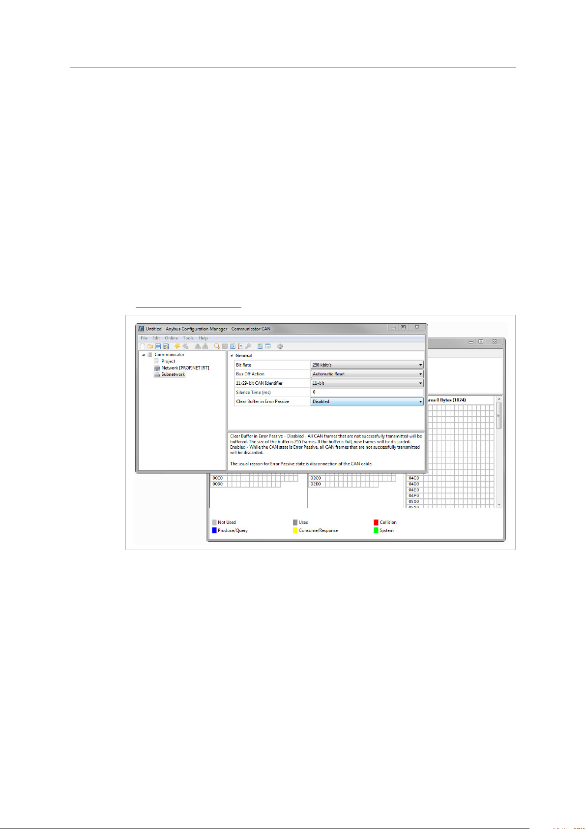
Anybus Communicator gateways are configured using Anybus Configuration Manager, a family of
configuration tools that have an easy to use graphical interface and that do not require
programming skills.
Anybus Configuration Manager and additional related software and documentation are available
at www.anybus.com/support.
5 (42)
Fig. 1 Anybus Configuration Manager
®
Anybus
Communicator™CAN PROFINET®IRT (2.32) User Manual
SCM-1202-035 1.2 en-US
Page 8

Description
Internal Memory
Input Data
(220 bytes)
CAN Subnetwork
Output Data
(220 bytes)
General Data
Higher Level Network
CAN Network:
Fieldbus:
CAN Network:
Fieldbus:
CAN Network:
Fieldbus:
Write Only
Read Only
Read Only
Write Only
Read/Write
-
Input Data Output Data General Data
0x000 0x200
0x0DB 0x2DB
0x400
0x7FF
2.2 Data Exchange Model
2.2.1 Overview
The data exchanged on the CAN subnetwork and the data exchanged on the higher level
network reside in the same internal memory in the Anybus Communicator CAN. In order to
exchange data with the CAN subnetwork, the higher level network simply reads and writes data
to memory locations that have been specified in Anybus Configuration Manager. The same
memory locations can then be exchanged on the CAN subnetwork.
6 (42)
Fig. 2 Memory buffer structure
The internal memory buffer is divided into three areas based on their function:
Input Data (220 bytes) This area can be read from by the higher level network.
Output Data (220 bytes) This area can be written to by the higher level network.
General Data
(up to 1024 bytes)
2.2.2 Memory Map
When building the CAN subnetwork configuration in Anybus Configuration Manager the areas in
the memory buffer will be mapped to the following memory locations:
This area cannot be accessed by the higher level network but can be used for
transfers between individual nodes on the subnetwork, or as a general “scratch
pad” for data.
The size of the General Data area is 1024 bytes. How much of that area that will
be used for communication depends on the configuration.
Fig. 3 Memory Map
Anybus®Communicator™CAN PROFINET®IRT (2.32) User Manual
The illustration shows the maximum available data areas in Anybus Communicator CAN. The actual
amount of memory that can be allocated depends on the fieldbus network used.
SCM-1202-035 1.2 en-US
Page 9

Description
2.3 PROFINET IRT Protocol
PROFINET is the open Industrial Ethernet standard for automation from PROFIBUS and PROFINET
International. The PROFINET IRT device provides PROFINET IO Isochronous Real Time
Communication.
PROFINET makes a clear distinction between fast cyclical data, IO Data, and acyclical data,
Record Data. PROFINET IO Data corresponds to what is generally referred to as I/O Data in
Anybus Communicator CAN PROFINET IRT (2.32). PROFINET Record Data is not supported.
Anybus Communicator CAN PROFINET IRT (2.32) acts as a PROFINET device (slave), which means
it can be accessed by a PROFINET controller (master), but will not initiate communication by
itself.
PROFINET IO Data (I/O Data)
PROFINET IO Data is exchanged cyclically and is built up by I/O modules. The actual I/O
configuration is determined by the PROFINET IO Controller. The modules are mapped to the
Input and Output Buffers in the order of their slot number.
The first two bytes of the I/O data area are reserved for the Control Word and the Status Word,
which are used by the IO Controller to control and report status on the nodes on the CAN
subnetwork. The remainder is available for real-time data transfer using PDOs.
7 (42)
GSD File
All PROFINET devices are associated with an XML-based GSD file. This file contains information
about the basic capabilities and configuration options of the device.
The latest version of the GSD file for Anybus Communicator CAN PROFINET IRT (2.32) can be
downloaded from www.anybus.com/support.
Anybus®Communicator™CAN PROFINET®IRT (2.32) User Manual
SCM-1202-035 1.2 en-US
Page 10
Description
2.4 CAN Network Protocol
2.4.1 General
The CAN protocol is message-based and can exchange up to 8 bytes of data in each message.
The protocol only acts as a data carrier, it is up to each application to define and interpret the
data content of the messages.
Data is exchanged using frames. Each frame has a unique identifier for the data it exchanges,
which also represents the message priority. Anybus Communicator CAN supports both 11-bit
(CAN 2.0A) and 29-bit (CAN 2.0B) identifiers, selected in the configuration.
CAN is essentially a produce-consume protocol, where all nodes listen to all messages. The
devices recognize what data to collect by the identifier in the CAN frame. Anybus Communicator
CAN is also able to act as a network master and issue queries that demand responses. Both
methods can be used within the same configuration.
2.4.2 Message Types
Anybus Communicator CAN features three CAN message types: Query-Response, Produce, and
Consume. These message types only specify the basic communication model, not the actual CAN
protocol. All three message types can be used in the same configuration.
8 (42)
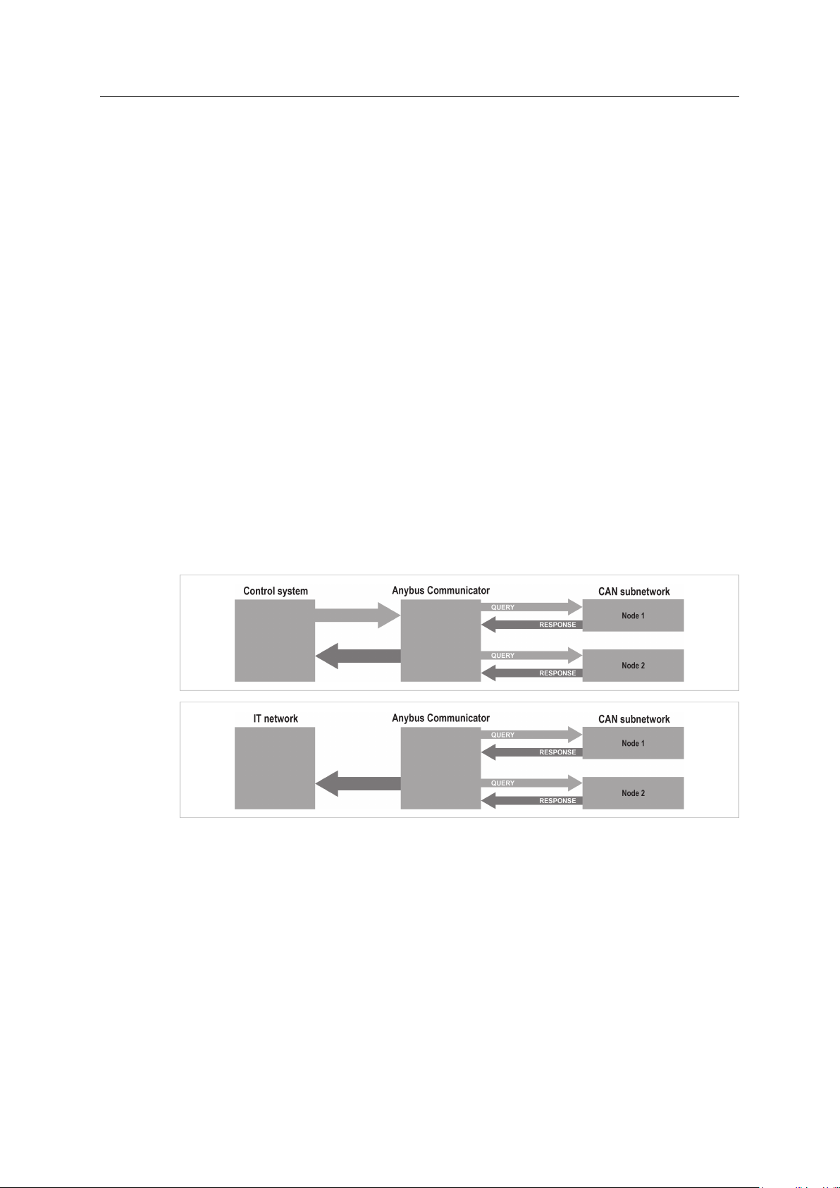
Query-Response
The Anybus Communicator CAN here acts as a master on the CAN subnetwork, and
communication takes place in a query-response fashion. The gateway sends a query and expects
a response within a specified timeout.
Fig. 4 Query-Response messaging
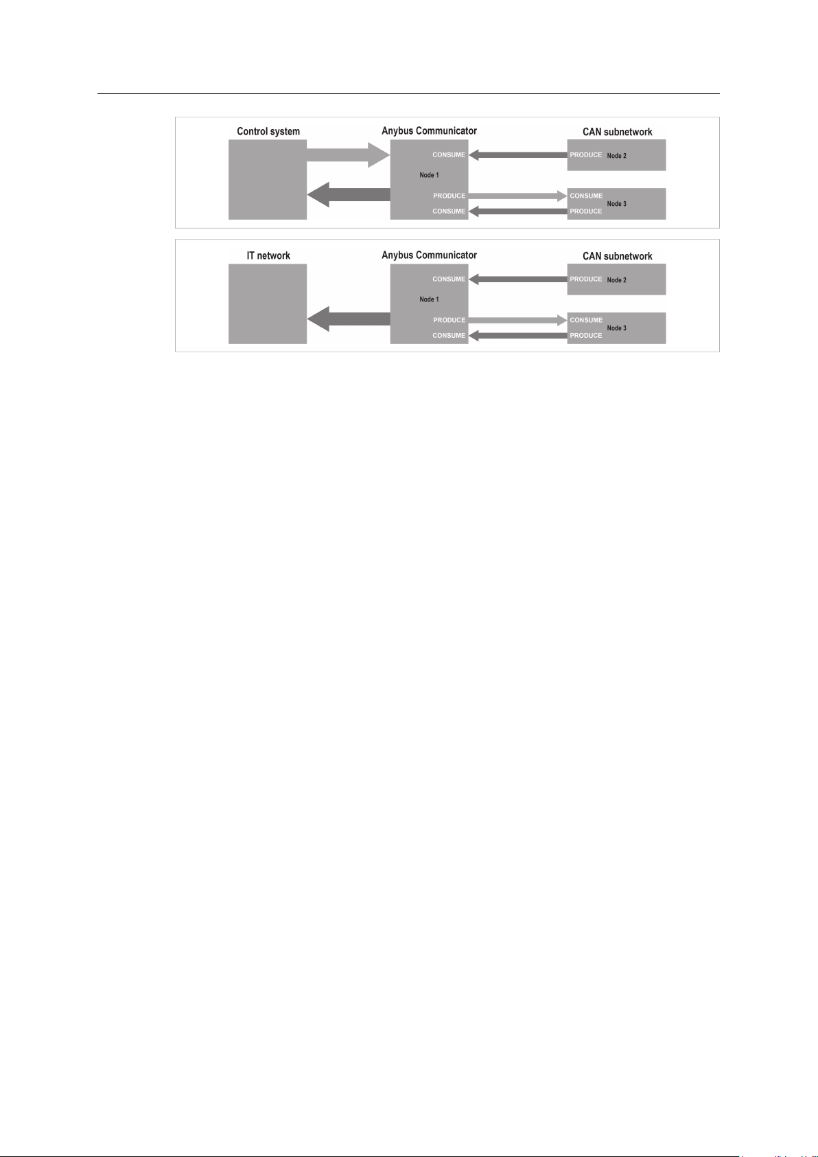
Produce and Consume
Here there is no master-slave relationship between the Anybus Communicator CAN and the
subnetwork nodes. Any node, including the gateway, may both produce and consume messages.
Nodes do not have to respond to messages, or wait for a query in order to send one. The
consumed data can be accessed from the higher level network, and vice versa.
Anybus®Communicator™CAN PROFINET®IRT (2.32) User Manual
SCM-1202-035 1.2 en-US
Page 11
Description
9 (42)
Fig. 5 Produce and Consume messages
®
Anybus
Communicator™CAN PROFINET®IRT (2.32) User Manual
SCM-1202-035 1.2 en-US
Page 12

Description
2.4.3 Protocol Building Blocks
The following building blocks are used in Anybus Configuration Manager to describe the
subnetwork communication.
10 (42)
Group
Transaction
Dynamic Transaction
CAN Frames
A group does not represent any specific device on the CAN subnetwork, it is only a
means to structure the transactions that have been defined for the gateway in Anybus
Configuration Manager.
Each group can be associated with any number of transactions, however the total
number of transactions in a configuration is limited to 128.
A transaction consists of one or more CAN frames. Each transaction is associated with a
set of parameters controlling how and when to use it on the subnetwork. There are 5
transaction types: produce, consume, query-response, dynamic produce and dynamic
consume. A group can contain transactions of all three types simultaneously.
A total of 128 transactions can be configured.
A dynamic transaction makes it possible for a network master to change selected
parameters during runtime. The parameters are mapped to the Output or General Data
areas and cannot be changed using Anybus Configuration Manager.
A dynamic transaction can only consist of a single CAN frame which in turn can only hold
one data object.
Only one dynamic produce transaction and one dynamic consume transaction can be
configured.
CAN frames are low level entities used to compose transactions. Each frame carries an
11-bit or 29-bit identifier and can hold up to 8 bytes of data.
A total of 256 CAN frames can be configured.
®
Anybus
Communicator™CAN PROFINET®IRT (2.32) User Manual
SCM-1202-035 1.2 en-US
Page 13

Description
2.4.4 Control and Status Words
The optional Control and Status Words can be used to control the startup mode of the Anybus
Communicator CAN and to read the status of the CAN subnetwork. The Control Word is always
mapped to the first two bytes of the output data area, and the Status Word to the first two bytes
of the input data area, with the Least Significant Byte in the first byte (byte 0).
Fig. 6 Memory buffers
The illustration shows the maximum available data areas in Anybus Communicator CAN. The actual
amount of memory that can be allocated depends on the fieldbus network used.
Control Word
The Control Word can be used to reset the CAN controller and to select the startup mode and/or
reboot the Anybus Communicator CAN.
11 (42)
Bit Name
15 - 3
2 Reset CAN
1
0
(reserved)
Reboot module 1 - Reboots the Anybus Communicator CAN (software reset)
Operation mode Sets the start-up operation mode of the Anybus Communicator CAN:
Description
1 - Resets the CAN controller (used when CAN interface is bus off)
0 - Idle (no new data is issued to the CAN subnetwork. Data received from the CAN
subnetwork is sent on to the higher level network.)
1 - Run (data is exchanged between CAN subnetwork and higher level network.)
Status Word
The Status Word holds information from the CAN subnetwork.
Bit Name
15 - 6
5 CAN overrun 0 - OK
4 Error passive
3
2 Reset CAN
1
0
(reserved)
Bus off
complete
(reserved)
Operation mode 0 - Idle
Description
1 - CAN reception overrun
0 - CAN interface is NOT in error passive state
1 - CAN interface is in error passive state
0 - Bus runnning
1 - Bus off
If set, the CAN controller has been reset (used when CAN interface is bus off)
1 - Run
®
Anybus
Communicator™CAN PROFINET®IRT (2.32) User Manual
SCM-1202-035 1.2 en-US
Page 14

Description
2.4.5 Transaction Live List
The optional Transaction Live List consists of a bit array where each bit corresponds to a
transaction on the CAN subnetwork (bit 0 corresponds to transaction 1 etc.). A set bit indicates
normal functionality. The bit is not set if the transaction is non-working or non-existent.
The live list is mapped in the Input data area of the memory, either at the start of the area or
directly after the Status word. From 8 transactions up to 128 transactions in steps of 8 can be
monitored using the live list. This means that up to 16 bytes of the input data area of the
memory can be occupied by the live list.
The latest live list can always be accessed in Anybus Configuration Manager, regardless of
whether the live list is mapped in the input data area or not.
12 (42)
Anybus®Communicator™CAN PROFINET®IRT (2.32) User Manual
SCM-1202-035 1.2 en-US
Page 15

Installation 13 (42)
3 Installation
This product contains parts that can be damaged by electrostatic discharge (ESD). Use
ESD prevention measures to avoid damage.
3.1 Installation Overview
These are the basic steps for installing Anybus Communicator CAN gateways.
Depending on the fieldbus network type there may also be configuration switches on the Anybus
Communicator CAN that need setting. See the following sections for more information.
Basic installation steps
1. Mount the Anybus Communicator CAN on the DIN rail.
2. Connect the CAN network.
3. Connect the fieldbus network.
4. Configure the fieldbus network interface (if applicable).
5. Connect the power cable and apply power.
6. Connect the USB cable between the gateway and a PC.
7. Download Anybus Configuration Manager from www.anybus.com/support
and install it on the PC following the instructions in the installer.
(Anybus Configuration Manager requires Microsoft
8. Continue to Configuration, p. 18
®
Windows XP or later)
Anybus®Communicator™CAN PROFINET®IRT (2.32) User Manual
SCM-1202-035 1.2 en-US
Page 16

Installation 14 (42)
3.2 Connectors and Indicators
3.2.1 External Parts
Fig. 7 Overview
1
LED indicators
2
DIN rail mount
3 Power connector
4 CAN connector
5 USB connector
6
PROFINET IRT network interface
3.3 DIN Rail Mounting
The unit must be electrically grounded through the DIN rail for EMC compliance.
Mount on DIN rail
1. Hook the unit onto the upper lip of
the rail and push gently downwards.
2. Push the unit towards the rail until it
snaps into place.
Remove from DIN rail
1. Push the unit gently downwards on the rail.
Anybus®Communicator™CAN PROFINET®IRT (2.32) User Manual
Fig. 8 Push down to mount or remove
SCM-1202-035 1.2 en-US
Page 17

Installation 15 (42)
2. Pull the bottom end of the unit free of the rail and remove it.
Anybus®Communicator™CAN PROFINET®IRT (2.32) User Manual
SCM-1202-035 1.2 en-US
Page 18

Installation 16 (42)
1 8
1 2
1
2
3
4
69
5 1(male)
3.4 CAN Interface
The CAN network connector is located on the bottom of the unit.
Pin Signal
2 CAN_L
3 CAN_GND
5
6 CAN_GND
7 CAN_H
1, 4, 8, 9
Shield
(reserved)
Fig. 9 CAN connector
3.5 PROFINET Interface
The PROFINET IRT interface contains a dual port Ethernet switch with RJ45 type connectors. The
two ports are labeled LAN 1 and LAN 2.
Pin Function
1 TD+
2 TD-
3 RD+
6 RD-
4, 5, 7, 8
(reserved)
Fig. 10 Ethernet connector (RJ45)
3.6 Power Connector
See also Technical Data, p. 39 regarding power supply requirements.
Pin
1 +24 VDC
2
Signal
Power Ground
3.7 USB Connector
The USB connector is used for connecting the Anybus Communicator CAN to a computer for
uploading and downloading configurations. The USB cable should be removed when not in use.
Pin Signal
1 +5 V input
2
3
4
Housing
USBDM (USB communication)
USBDP (USB communication)
Signal ground
Cable shield
Fig. 11 Power connector
Fig. 12 USB type B connector
Anybus®Communicator™CAN PROFINET®IRT (2.32) User Manual
SCM-1202-035 1.2 en-US
Page 19

Installation 17 (42)
1 2
3
546
3.8 LED Indicators
The LED indicators provide diagnostic information about data communication and status of the
network interfaces as well as general device status.
LED 1 to 4
LED 5
LED 6 Device status
LED
1 - Network Status Off Offline
2 - Module Status Off No power or initializing
3 - Link/Activity 1
4 - Link/Activity 2
Indication Meaning
Green
Green, 1 flash Online (STOP)
Red Fatal error
Red, 1 flash
Red, 2 flashes IP address error
Red, 3 flashes Configuration error
Alternating red/green
Green
Green, 1 flash
Red Fatal error
Alternating red/green
Off No power or no link detected
Green
Green, flickering
PROFINET IRT network status
CAN network status
– No power
– No connection to IO Controller
Online (RUN)
– Connection to IO Controller
– Connection to IO Controller
– IO Controller in STOP state or IO data bad
– RT synchronization not finished
Station name error
Firmware update in progress
Normal operation
Diagnostic event present
Firmware update in progress
Link OK
Transmitting/receiving data
LED
5 - CAN Subnet Status Off
Device Status
®
Anybus
Communicator™CAN PROFINET®IRT (2.32) User Manual
Indication Meaning
No power or no CAN communication
Green Running, no errors or timeout
Red. flashing Transaction error, timeout, or CAN subnet stopped
Red Fatal error
Off No power or initializing
Green Running
Green, flashing Idle
Red Fatal error
Alternating red/green
Configuration error
SCM-1202-035 1.2 en-US
Page 20

Configuration 18 (42)
4 Configuration
4.1 Configuration Overview
Device Description Files
A device description file contains a description of a network device, its functions, object
dictionary implementations, etc., and is used when configuring the network interface. The device
description file can be referred to as a DDF, EDS, GSD, etc., depending on the type of network.
The latest versions of the device description files can be downloaded from
www.anybus.com/support.
Basic steps when configuring Anybus Communicator CAN PROFINET IRT (2.32)
1. Install, connect and power up the Anybus Communicator CAN gateway (if you have not
already done so). See also Installation, p. 13.
2. Download Anybus Configuration Manager from www.anybus.com/support and install it.
3. Download the latest device description file for Anybus Communicator CAN PROFINET IRT
(2.32) from www.anybus.com/support.
4. Build your configuration using Anybus Configuration Manager and download it to the
gateway.See Anybus Configuration Manager, p. 24.
5. Install the appropriate device description file in the PROFINET IRT configuration tool.
6. Configure the PROFINET IRT network as required. Make sure that the configuration matches
the configuration present in the Anybus Communicator CAN.
Anybus®Communicator™CAN PROFINET®IRT (2.32) User Manual
SCM-1202-035 1.2 en-US
Page 21

Configuration 19 (42)
4.2 Network Configuration
To be able to communicate over Ethernet, the PROFINET network interface needs a valid TCP/IP
configuration. This section explains some basic concepts and describes how to configure the
TCP/IP settings using the IPconfig software tool.
When Ethernet communication has been established the TCP/IP settings can also be changed
from the web interface. See Web Pages, p. 23.
4.2.1 Basic TCP/IP Concepts
IP Address
The IP address is used to identify each node on a TCP/IP network. IP addresses are written as
four decimal integers (0–255) separated by dots, where each integer represents the binary value
of one byte of the IP address. This is known as dot-decimal notation.
Example: 10000000 00001010 00000010 00011110 is written as 128.10.2.30
The following IP addresses are reserved for special purposes and cannot be used:
0.n.n.n
127.n.n.n
n.n.n.0
n.n.n.255
First byte zero — used for broadcast messages
First byte 127 — used for loopback addresses to the local host
Last byte zero — identifies a whole network/subnet
Last byte 255 — used for broadcast messages
Subnet Mask
The IP address is divided into three parts: Net ID, Subnet ID and Host ID. A subnet mask is a 32bit binary pattern, where a set bit allocates a bit for Network/Subnet ID, and a cleared bit
allocates a bit for the Host ID. The subnet mask is usually written in dot-decimal notation.
Example: To make the IP address 128.10.2.30 belong to subnet 128.10.2, the subnet
mask must be 255.255.255.0.
Default Gateway
For devices to be able to communicate over Ethernet they must either belong to the same
subnet or communicate via a gateway or router.
A gateway or router routes communication between networks, i.e. it enables the nodes on one
network to access the nodes on another. The default gateway address in the TCP/IP settings of
your product specifies the IP address of the gateway or router on the local network.
Anybus®Communicator™CAN PROFINET®IRT (2.32) User Manual
SCM-1202-035 1.2 en-US
Page 22

Configuration 20 (42)
4.2.2 TCP/IP Configuration
Installing the IPconfig Utility
IPconfig is a Windows-based tool for configuration of TCP/IP settings in HMS devices. The tool
will detect all compatible and active HMS devices on the local network.
1. Download IPconfig from www.anybus.com/support.
2. Unpack the contents of the zip archive and run the installer program.
Scanning for Connected Devices
When IPconfig is started it will automatically scan all available local networks for HMS devices.
Detected devices will be listed in the main window. To refresh the list, click on Scan.
Fig. 13 IPconfig main window
IP
SN
GW
DHCP
Version Firmware version
Type
MAC
IP address of the device
Subnet mask
Default gateway
Automatically managed IP configuration
Product name
Ethernet MAC address (System ID)
®
Anybus
Communicator™CAN PROFINET®IRT (2.32) User Manual
SCM-1202-035 1.2 en-US
Page 23

Configuration 21 (42)
Ethernet Configuration
To change the IP settings for a device, double-click on the entry in the main window or right-click
on it and select Configuration.
Fig. 14 Ethernet configuration
Enter static IP settings as required, or select DHCP if using dynamic IP addressing.
Do not enable DHCP if there is no DHCP server available on the network.
You can add a name for the device in the Hostname field. Only characters a–z, A–Z, 0–9 and _
(underscore) are allowed.
The default password for changing IP settings is blank (no password). If a password has been set
for the device you must enter it to be able to change the settings.
To set a new password, check the Change password box and enter the current password in the
Password field, then enter the new password in the New password field.
For security reasons the default password should always be changed.
Click on Set to save the new settings. The device will reboot automatically.
Anybus®Communicator™CAN PROFINET®IRT (2.32) User Manual
SCM-1202-035 1.2 en-US
Page 24

Configuration 22 (42)
IPconfig Settings
Additional settings for IPconfig can be accessed by clicking on Settings.
Fig. 15 IPconfig settings
Network Interface
Check this option to select a specific network interface to use when scanning for devices from a
computer which has more than one interface. If this option is left unchecked, all available
networks will be scanned.
Internal DHCP Server
If a device has been set to use DHCP but there is no DHCP server on the network, the device may
not be detected by IPconfig. To recover access to the device an internal DHCP server in IPconfig
can be temporarily activated:
1. Click the checkbox for Internal DHCP Server, then click OK. IPconfig will automatically
refresh the scan and list the missing device in the main window.
2. Select the device and configure it to use static IP addressing instead of DHCP.
3. Disable the internal DHCP server.
Do not enable the internal DHCP server if there is already an active DHCP server on the
network.
4.2.3 DCP (Discovery and Control Protocol)
Anybus Communicator CAN PROFINET IRT (2.32) PROFINET IRT supports the DCP protocol, which
allows a PROFINET IO Controller/Supervisor to change the network settings during runtime.
Anybus®Communicator™CAN PROFINET®IRT (2.32) User Manual
SCM-1202-035 1.2 en-US
Page 25

Configuration 23 (42)
4.3 Web Pages
Network configuration settings and status of the PROFINET IRT network interface can be
accessed by pointing a web browser to the IP address of the interface.
Module Overview
Fig. 16 Overview tab
Provides basic information about the Anybus Communicator CAN including the serial number
and the installed firmware version.
Network Status
Fig. 17 Status tab
Displays an overview of the current network status.
Network Configuration
Fig. 18 Configuration tab
Provides access to the TCP/IP network settings. These parameters can also be configured using
the IPconfig tool.
Anybus®Communicator™CAN PROFINET®IRT (2.32) User Manual
SCM-1202-035 1.2 en-US
Page 26

Anybus Configuration Manager 24 (42)
5 Anybus Configuration Manager
5.1 Main Window
Fig. 19 Anybus Configuration Manager - Communicator CAN
1: Menus and Toolbar
The most common menu commands can also be carried out by clicking on a button in the toolbar.
Moving the mouse cursor over a toolbar button will display a tooltip explaining its function.
2: Parameter List
Lists the parameters or options related to the currently selected entry in the Navigation Tree.
Values can be selected from a dropdown menu or entered manually depending on the parameter.
Values can be specified in either decimal or hexadecimal format.
Example: The decimal value 42 can also be entered as 0x2A.
Moving the mouse cursor over a parameter in this window will show a help text in the
Information Window explaining how to use the parameter.
3: Information Window
Displays a help text describing the current parameter.
4: Navigation Tree
A hierarchic tree view of the configuration, divided into three main sections:
Project
Network Settings for the higher level network
Subnetwork Settings for the CAN subnetwork
Information about the current configuration project
Select an entry to display its available parameters in the Parameter List. Right-click on the entry
to show additional options.
Anybus®Communicator™CAN PROFINET®IRT (2.32) User Manual
SCM-1202-035 1.2 en-US
Page 27

Anybus Configuration Manager 25 (42)
5.2 Basic Settings
For more detailed explanations of each configuration setting, see the help texts in the
Information Window.
5.2.1 Project
Used to store project information such as project name, project creator, version and description.
5.2.2 Network Settings
General
During startup the fieldbus interface is initialized to fit the configuration created in Anybus
Configuration Manager. Some initialization parameters can optionally be set manually to provide
better control over how the data shall be treated by the Anybus Communicator CAN.
Network Type
The higher level network type must be selected here in order to create a valid configuration.
5.2.3 Communicator Settings
Additional settings for the Anybus Communicator CAN.
General
Parameter Comment
Control/Status Word If enabled, the Control/Status Word will occupy the first two bytes of the Output/Input
Start-up Operation Mode Decides the start-up mode of the CAN subnetwork if the Control Word is enabled.
Transaction Live List
Statistics
Parameter Comment
Counters
Receive Counter Address Enter the address in the input data area where the receive counter shall be mapped. The
Transmit Counter Address Enter the address in the input data area where the transmit counter shall be mapped.
areas of the memory.
To avoid memory address collisions this parameter should be enabled before adding
frames to the configuration.
If the Transaction Live List is enabled it is mapped from the beginning of the input area
or, if the Control/Status Word is enabled, after the Status Word. It is possible to map
from 8 to 128 transactions, in steps of 8. Each transaction is represented by a bit that
tells the system whether the transaction is alive or not.
The receive counter and the transmit counter count successful CAN messages on the
subnetwork. If enabled, the counters can be mapped to the input data area. The first
free address in the input data area is selected by default. The counters can be disabled
and enabled separately.
To avoid memory address collisions this parameter should be enabled before adding
frames to the configuration.
The messages are counted only if they have been configured in Anybus Configuration
Manager.
receive counter occupies 2 bytes.
The transmit counter occupies 2 bytes.
Fatal Event
Parameter
Action
®
Anybus
Communicator™CAN PROFINET®IRT (2.32) User Manual
Values
Stay in Safe-State In case of a fatal software event, the Anybus Communicator
Software Reset In case of a fatal software event, the software will be reset and
Comment
CAN will be locked in the safe state.
the Anybus Communicator CAN will be restarted.
SCM-1202-035 1.2 en-US
Page 28

Anybus Configuration Manager 26 (42)
5.2.4 Subnetwork Settings
Settings for the CAN subnetwork.
Parameter
Bit Rate
Bus Off Action
11/29-bit CAN Identifier
Silence Time (ms)
Clear Buffer in Error Passive
Values
20 kbit/s
50 kbit/s
100 kbit/s
125 kbit/s
200 kbit/s
250 kbit/s
500 kbit/s
800 kbit/s
1000 kbit/s
No Action
Automatic Reset
11 bit
29 bit
0 - 65535
Disabled/Enabled
Comment
Select the bit rate on the CAN subnetwork.
Select what will happen to the CAN controller when the CAN
subnetwork goes bus off.
When the Control/Status Word is enabled this parameter will
be disabled (No Action).
Select CAN identifier size on the subnetwork
If there are configured transactions when this parameter is
changed, the following will happen:
• A change from 11 bit to 29 bit identifier will cause the
identifier to be padded with zeroes up to 29 bits, keeping
the 11 bits at the same location.
• A change from 29 bit to 11 bit identifier will cause the
upper 18 bits to be deleted and the lower 11 bits kept.
This may in some cases cause faulty CAN identifiers.
Default = 0 (disabled)
The minimum time that must elapse between the end of a
message and the beginning of the next message. If a device on
the CAN subnetwork is slow and/or does not have a message
queue, it may be necessary to enter a delay between the
messages to ensure that they are handled correctly. The delay
is set in milliseconds.
Disabled: All CAN frames that are not successfully transmitted
will be buffered. The size of the buffer is 255 frames. If the
buffer is full, new frames will be discarded.
Enabled: While the CAN state is Error Passive, all CAN frames
that are not successfully transmitted will be discarded.
The usual reason for Error Passive state is disconnection of the
CAN cable.
®
Anybus
Communicator™CAN PROFINET®IRT (2.32) User Manual
SCM-1202-035 1.2 en-US
Page 29

PROFINET Asset Management
6 PROFINET Asset Management
6.1 Asset Management Record
With the asset management record functionality data about the assets available on a non
PROFINET network can be recorded and read out over a PROFINET network.
Together with the Identification & Maintenance data functionality an extensive registration of
devices and machines is possible, even in facilities where the devices are not installed in the
PROFINET environment.
Factory owners and system integrators can collect data about devices installed beyond the
Anybus gateway.
The recorded data can be used as basis for the design of easier maintenance and operation
processes, despite the increasing complexity of processes and associated machines.
6.2 Recording and Reading Data
An asset management file containing all the assets and their corresponding data on the non
PROFINET network is created and uploaded via an FTP server to the Gateway file system.
The asset management file can be transferred from a computer connected to a PROFINET
network.
27 (42)
Fig. 20 The Asset Management Default Mode
By using the superposed parameter channel mode it is also possible to transfer the asset
management file from a PLC connected to a non PROFINET network.
For further details about the superposed parameter channel mode, please refer to
www.anybus.com/support.
Anybus®Communicator™CAN PROFINET®IRT (2.32) User Manual
SCM-1202-035 1.2 en-US
Page 30

PROFINET Asset Management
Record Data
Data about the assets on the non PROFINET network is recorded and stored in an XML file or an
binary file.
Read Data
Each time an instance is requested the asset management data is read out over the PROFINET
network.
The recorded asset management data can be downloaded to a computer connected to the
PROFINET network.
6.3 Supported File Formats
The following file formats are supported for the asset management file.
28 (42)
Format
XML XML Version 1.0
Binary file
Little-endian
Version
N/A
6.4 Supported Asset Management Records
Supported asset management records:
• Unique ID
• Location
• Hardware Revision
• Annotation
• Order ID
• Serial Number
• Software Revision
• Serial Number
Anybus®Communicator™CAN PROFINET®IRT (2.32) User Manual
SCM-1202-035 1.2 en-US
Page 31

PROFINET Asset Management
6.5 XML Based Asset Management
6.5.1 Creating the Asset Management XML File
Creating the asset management XML file:
1. List all assets and their corresponding data on the non PROFINET network.
2. Create an XML file that include one asset management record for each asset.
Repeat all the attributes after each other.
3. When all attributes are listed, close the element by using a closing entry.
4. Name the XML file asset_mgmt.
6.5.2 XML File Size Limitation
The size of the asset management file may not exceed 95 kb.
Up to 32 instances can be added.
In order to keep the file size small, consider the following:
29 (42)
• Keep strings as short as possible.
• Do not pad with empty spaces for strings.
• Try to use as few spaces as possible for indentation in the file.
• The number of white-space also affects the file size.
• Avoid using optional name strings.
6.5.3 XML Attribute Name and Data Format
The order of the elements is significant for the XML schema to work with the Anybus Gateways.
If the XML schema is incorrect, the XML file will not work and no data will be recorded.
When creating the XML file, add the elements and their attributes in the same order as the
attribute names are listed in the table below.
Each element consists of a series of attributes and their various data.
Each attribute is described by one entry.
The supported attribute names are specified in the table.
Example 1: XML element including an attribute with the location record.
<AbccAttribute>
<Name Value="Location Type"/>
<Attribute Value="3"/>
<Data Value="1"/>
</AbccAttribute>
Anybus®Communicator™CAN PROFINET®IRT (2.32) User Manual
SCM-1202-035 1.2 en-US
Page 32

PROFINET Asset Management
Attribute Name and Data Format
Attribute Name
AM info Type
Location Type
AM Type Identification
IM Hardware Revision
IM Annotation
IM Order ID String of length X Maximum number of elements in array: 64.
IM Serial Number String of length X Maximum number of elements in array: 16.
AM Software Revision String of length X Maximum number of elements in array: 64.
AM Hardware Revision String of length X Maximum number of elements in array: 64.
IM Software Revision
IM Unique Identifier Array of Unsigned 8
Location LT
Location SS
AM Device Identification
30 (42)
Data Format
Unsigned 8 The value can be set in either of two formats, 0x12 or 18.
Unsigned 16 The value can be set in either of two formats, 0x1234 or
String of length X Maximum number of elements in array: 64.
String
Length is 16
Array of Unsigned 16
Length is up to 12
elements.
Array of Unsigned 16
Length is 4.
Description
4660.
Format of the string shall be C.X.Y.Z.
C is one character.
X, Y and Z represent a value between 0 and 255.
X – Major version
Y – Minor version
Z – Internal
Format of the value shall be 0xXX;0xYY…0xZZ.
16 values in hex-format, where each value is separated by a
“;”.
Format of the value shall be 0xXXXX;0xYYYY…0xZZZZ.
Up to 12 values in hex-format, where each value is separated
by a “;”.
Format of the value shall be 0xXXXX;0xYYYY…0xZZZZ.
4 values in hex-format, where each value is separated by a “;”.
®
Anybus
Communicator™CAN PROFINET®IRT (2.32) User Manual
SCM-1202-035 1.2 en-US
Page 33

PROFINET Asset Management
6.5.4 Asset Management XML File Structure Example
The code example presented below can be used as a guide when creating the asset management
XML file.
31 (42)
Fig. 21 Asset management XML file structure example
®
Anybus
Communicator™CAN PROFINET®IRT (2.32) User Manual
SCM-1202-035 1.2 en-US
Page 34

PROFINET Asset Management
6.6 Binary Based Asset Management
6.6.1 Creating the Asset Management Binary File
Creating the asset management binary file:
1. List all assets and their corresponding data on the non PROFINET network.
2. Create an Binary file that include a asset management record for each asset.
Repeat all the attributes after each other.
3. When all attributes are listed, close the element by using a closing entry.
4. Name the bin file asset_mgmt.
6.6.2 Binary File Size Limitation
The size of the asset management file may not exceed 12 kb.
32 instances can be added, instance 1 to 32.
32 (42)
In order to keep the file size small, consider the following:
• Keep strings as short as possible.
• Do not pad with empty spaces for strings.
6.6.3 Binary File Header
Omitted attributes are disabled or set to their default value.
The size of the file header is 70 bytes.
The supported file headers are specified in the table.
Supported File Headers
File Header Byte Number
File format
version
File checksum
Byte offset to
Instance 1
Byte offset to
Instance 2
Byte offset to
Instance 32
Instance data
0-1 UINT16
2-5 UINT32
6-7 UINT16
8-9
68-69
70-x
Data Type Comment
Version number of the file format.
Set to 0.
Used for version control of the file.
Not used by the gateway.
If not used, the field must be set to zero.
Byte offset to the start of the data describing Asset
management Instance X.
Set to zero if instance is not used.
N/A
Data for the instance(s), as specified below.
®
Anybus
Communicator™CAN PROFINET®IRT (2.32) User Manual
SCM-1202-035 1.2 en-US
Page 35

PROFINET Asset Management
6.6.4 Binary Instance Data
Each instance consists of a series of attributes and their respective data.
Attribute Description
Each attribute is described by one entry.
33 (42)
Attribute Description Byte number
Attribute number
Data length
Attribute data
0 UINT8
1 UINT8
2–x
Data type Comment
Depends on the
attribute being
described.
Attribute Closure Description
Use a closing entry to close the instance data.
Attribute Description Byte number
Closure
0–1 UINT16
Data type Comment
Attribute number of the data being described.
Optional checksum.
Shall represent the number of data bytes
following.
Not used by the gateway.
Data for the attribute.
Format shall be as described for the data-type.
Not needed for strings padding or termination.
Data-field which tell that there will not follow
any more attributes for this instance.
Set to value 0xFFFF.
®
Anybus
Communicator™CAN PROFINET®IRT (2.32) User Manual
SCM-1202-035 1.2 en-US
Page 36

PROFINET Asset Management
Attribute Name and Data Format
Supported attribute names and data formats.
Attribute Name and Data Format
Attribute Name
AM info Type
Location Type
AM Type Identification
IM Hardware Revision
IM Annotation
IM Order ID String of length X Maximum number of elements in array: 64.
IM Serial Number String of length X Maximum number of elements in array: 16.
AM Software Revision String of length X Maximum number of elements in array: 64.
AM Hardware Revision String of length X Maximum number of elements in array: 64
IM Software Revision Array of Unsigned 8
IM Unique Identifier Array of Unsigned 8
Location LT
Location SS
AM Device Identification
Data Format
Unsigned 8 The value is set as one byte value.
Unsigned 16 The value is set with two bytes, little-endian format.
String of length X Maximum number of elements in array: 64.
Length is 4
Length is 16
Array of Unsigned 16
Length is up to 12
elements.
Array of Unsigned 16
Length is 4.
Description
First byte is a character.
Bytes 2, 3 and 4 represent the version in the format X.Y.Z
where X, Y and Z represent a value between 0 and 255.
C is one character.
X, Y and Z represent a value between 0 and 255.
X – Major version
Y – Minor version
Z – Internal
Format is 16 bytes.
Each Unsigned 16 comprises two bytes, where each two bytes
form an Unsigned 16 in little-endian format.
The number of Unsigned 16’s can be up to 12, placed directly
after each other
Each Unsigned 16 comprises two bytes, where each two bytes
form an Unsigned 16 in little-endian format.
The number of Unsigned 16’s shall be 4, placed directly after
each other.
34 (42)
®
Anybus
Communicator™CAN PROFINET®IRT (2.32) User Manual
SCM-1202-035 1.2 en-US
Page 37

PROFINET Asset Management
6.6.5 Asset Management Binary File Example
The binary file structure example presented below can be used as a guide when creating the
asset management binary file.
Only instance 1 is supported.
For instance 1, only attribute 1 and 2 are defined.
35 (42)
Fig. 22 Binary file example
®
Anybus
Communicator™CAN PROFINET®IRT (2.32) User Manual
SCM-1202-035 1.2 en-US
Page 38

PROFINET Asset Management
6.7 Uploading the Asset Management File to the FTP Server
Use Windows Explorer or a standard FTP client to transfer the asset management file to the FTP
server.
When the superposed parameter channel function is enabled, transfer the asset management
file via a PLC connected to the network where the gateway is installed.
6.7.1 Transferring the Asset Management File from Windows Explorer
Transfer the asset management file, XML or binary file, to the FTP server using Windows Explorer.
Before You Begin
Use only one of the file formats, XML format or binary format.
Only upload one single file on the FTP server.
• Name the asset management file: asset_mgmt
• The default port is FTP port 21.
36 (42)
• Make sure that the gateway and your computer are connected to the PROFINET network to
be used.
Procedure
Fig. 23 The FTP Server root folder
1. Open an Windows Explorer Window.
2. Click to select the Address bar.
3. Enter ftp://Username:Password@IPaddress.
– Replace “Username” and “Password” with a valid username and password combination.
– Replace ‘IPaddress’ with the IP address of the PROFINET interface.
4. Press Enter.
Anybus®Communicator™CAN PROFINET®IRT (2.32) User Manual
SCM-1202-035 1.2 en-US
Page 39

PROFINET Asset Management
Fig. 24 Application folder with an asset_mgmt.xml file
5. Open the application folder and save the asset management file, XML or Binary file, in the
folder.
37 (42)
Anybus®Communicator™CAN PROFINET®IRT (2.32) User Manual
SCM-1202-035 1.2 en-US
Page 40

This page intentionally left blank
Page 41

Appendix A: Technical Data 39 (42)
A Technical Data
A.1 General Specifications
Model name Anybus Communicator CAN PROFINET IRT (2.32)
Order code
Dimensions (L x W x H)
Weight
Operating temperature
Storage temperature
Humidity range 5–95 % RH, non-condensing (IEC 60068-2-30)
Power supply 24 V ±10 % DC regulated power source
Current consumption
Galvanic isolation Yes, on both network sides
Mechanical rating
Mounting
Certifications
AB7328
120 x 75 x 27 mm
150 g
-25 to +55 °C (IEC 60068-2-1 and IEC 60068-2-2)
-40 to +85 °C (IEC 60068-2-1 and IEC 60068-2-2)
Typical: 100 mA @ 24 VDC
Maximum: 250 mA @ 24 VDC
IP20, NEMA rating 1
DIN rail (EN 50022)
Network shield conductance via DIN rail
CE
A.2 CAN Interface
Maximum baud rate
CAN connector
CAN specification CAN 1.0, 2.0A and 2.0B
A.3 PROFINET IRT Interface
PROFINET specification
PROFINET functionality Isochronous Real-Time (IRT) communication
Isochronous cycle times
Maximum I/O data
Ethernet
1 Mbit/s
D-sub 9 Male (included)
2.32
Conformance supporting Class A, B and C
Media Redundancy Protocol (MRP) support
Discovery and Configuration Protocol (DCP) support
Acyclic Data exchange (Record Data Requests)
Asset Management
0.250 ms to 16 ms
Up to 512 byte in each direction
100 Mbit/s, full duplex (fixed)
Dual port cut-through switch, RJ45 connectors
Ethernet Transport Provider support
®
Anybus
Communicator™CAN PROFINET®IRT (2.32) User Manual
SCM-1202-035 1.2 en-US
Page 42

Appendix B: Licenses 40 (42)
B Licenses
This product includes software developed by Carnegie Mellon, the Massachusetts Institute of Technology, the University
of California, and RSA Data Security:
Copyright 1986 by Carnegie Mellon.
Copyright 1983,1984,1985 by the Massachusetts Institute of Technology
Copyright © 1988 Stephen Deering.
Copyright © 1982, 1985, 1986, 1992, 1993 The Regents of the University of California. All rights reserved.
This code is derived from software contributed to Berkeley by Stephen Deering of Stanford University.
Redistribution and use in source and binary forms, with or without modification, are permitted provided that the
following conditions are met:
• Redistributions of source code must retain the above copyright notice, this list of conditions and the following
disclaimer.
• Redistributions in binary form must reproduce the above copyright notice, this list of conditions and the following
disclaimer in the documentation and/or other materials provided with the distribution.
• Neither the name of the University nor the names of its contributors may be used to endorse or promote products
derived from this software without specific prior written permission.
THIS SOFTWARE IS PROVIDED BY THE REGENTS AND CONTRIBUTORS “AS IS” AND ANY EXPRESS OR IMPLIED
WARRANTIES, INCLUDING, BUT NOT LIMITED TO, THE IMPLIED WARRANTIES OF MERCHANTABILITY AND FITNESS FOR A
PARTICULAR PURPOSE ARE DISCLAIMED. IN NO EVENT SHALL THE REGENTS OR CONTRIBUTORS BE LIABLE FOR ANY
DIRECT, INDIRECT, INCIDENTAL, SPECIAL, EXEMPLARY, OR CONSEQUENTIAL DAMAGES (INCLUDING, BUT NOT LIMITED
TO, PROCUREMENT OF SUBSTITUTE GOODS OR SERVICES; LOSS OF USE, DATA, OR PROFITS; OR BUSINESS
INTERRUPTION) HOWEVER CAUSED AND ON ANY THEORY OF LIABILITY, WHETHER IN CONTRACT, STRICT LIABILITY, OR
TORT (INCLUDING NEGLIGENCE OR OTHERWISE) ARISING IN ANY WAY OUT OF THE USE OF THIS SOFTWARE, EVEN IF
ADVISED OF THE POSSIBILITY OF SUCH DAMAGE.
*****************************************************************************
Copyright © 1990-2, RSA Data Security, Inc. All rights reserved.
License to copy and use this software is granted provided that it is identified as the “RSA Data Security, Inc. MD4
Message-Digest Algorithm” in all material mentioning or referencing this software or this function.
License is also granted to make and use derivative works provided that such works are identified as “derived from the
RSA Data Security, Inc. MD4 Message-Digest Algorithm” in all material mentioning or referencing the derived work.
RSA Data Security, Inc. makes no representations concerning either the merchantability of this software or the suitability
of this software for any particular purpose. It is provided “as is” without express or implied warranty of any kind.
These notices must be retained in any copies of any part of this documentation and/or software.
*****************************************************************************
Copyright © 1991-2, RSA Data Security, Inc. Created 1991. All rights reserved.
License to copy and use this software is granted provided that it is identified as the “RSA Data Security, Inc. MD5
Message-Digest Algorithm” in all material mentioning or referencing this software or this function.
License is also granted to make and use derivative works provided that such works are identified as “derived from the
RSA Data Security, Inc. MD5 Message-Digest Algorithm” in all material mentioning or referencing the derived work.
RSA Data Security, Inc. makes no representations concerning either the merchantability of this software or the suitability
of this software for any particular purpose. It is provided “as is” without express or implied warranty of any kind.
These notices must be retained in any copies of any part of this documentation and/or software.
®
Anybus
Communicator™CAN PROFINET®IRT (2.32) User Manual
SCM-1202-035 1.2 en-US
Page 43

This page intentionally left blank
Page 44

last page
© 2019 HMS Industrial Networks
Box 4126
300 04 Halmstad, Sweden
info@hms.se SCM-1202-035 1.2 en-US / 2019-04-12 / 12861
 Loading...