

Page 1

+$/067$'&+,&$*2.$5/658+(72.<2%(,-,1*0,/$1208/+286(&29(175<381(&23(1+$*(1
Connecting Devices
TM
INVERTER
Plug-in option
A8NDPV1
INSTRUCTION MANUAL
PROFIBUS communication interface
Doc.Id. HMSI-216-127
Rev. 1.01
Art. no.: 280272
05042019
Version B
Versi on chec k
Page 2

Page 3

Important User Information
This document is intended to provide a good understanding of the functionality offered by the
A8NDPV1 PROFIBUS Option Board. The document only describes the features that are specific to
the option board. For general information regarding the FR-A800 or FR-F800 inverter, consult the
FR-A800 or FR-F800 inverter design guides.
The reader of this document is expected to be familiar with high level software design, and communication systems in general. The use of advanced PROFIBUS-specific functionality may require
in-depth knowledge in PROFIBUS networking internals and/or information from the official
PROFIBUS specifications. In such cases, the people responsible for the implementation of this
product should either obtain the PROFIBUS specification to gain sufficient knowledge or limit
their implementation in such a way that this is not necessary.
Liability
Every care has been taken in the preparation of this manual. Please inform HMS Industrial Networks AB of any inaccuracies or omissions. The data and illustrations found in this document are
not binding. We, HMS Industrial Networks AB, reserve the right to modify our products in line
with our policy of continuous product development. The information in this document is subject
to change without notice and should not be considered as a commitment by HMS Industrial Networks AB. HMS Industrial Networks AB assumes no responsibility for any errors that may appear
in this document.
There are many applications of this product. Those responsible for the use of this device must ensure that all the necessary steps have been taken to verify that the applications meet all performance and safety requirements including any applicable laws, regulations, codes, and standards.
HMS Industrial Networks AB will under no circumstances assume liability or responsibility for any
problems that may arise as a result from the use of undocumented features, timing, or functional
side effects found outside the documented scope of this product. The effects caused by any direct or indirect use of such aspects of the product are undefined, and may include e.g. compatibility issues and stability issues.
The examples and illustrations in this document are included solely for illustrative purposes. Because of the many variables and requirements associated with any particular implementation,
HMS Industrial Networks AB cannot assume responsibility for actual use based on these examples and illustrations.
Intellectual Property Rights
HMS Industrial Networks AB has intellectual property rights relating to technology embodied in
the product described in this document. These intellectual property rights may include patents
and pending patent applications in the US and other countries.
Trademark Acknowledgements
Anybus® is a registered trademark of HMS Industrial Networks AB. All other trademarks are the
property of their respective holders.
A8NDPV1 PROFIBUS Option Board I
Page 4

CAUTION
• This is a class A product. In a domestic environment this product may cause radio interference in which case the user may be required to take adequate measures.
• ESD Note
This product contains ESD (Electrostatic Discharge) sensitive parts that may be damaged if
ESD control procedures are not followed. Static control precautions are required when handling the product.
Failure to observe this may cause damage to the product.
A8NDPV1 PROFIBUS Option Board User Manual
Rev 1.01
Copyright© HMS Industrial Networks AB
March 2014 Doc Id HMSI-216-127
II Doc.Id. HMSI-216-127
Doc.Rev. 1.01
Page 5
Thank you for choosing this Mitsubishi Inverter plug-in option for the Mitsubishi FR-A800 or FR-
WAR NING
CAUTION
CAUTION
F800 Series Inverter. This Instruction Manual gives handling information and precautions for use
of this equipment. Incorrect handling may cause an unexpected failure or damage. In order to ensure optimal performance, please read this manual carefully prior to use of the equipment.
Please forward this manual to the end user of the equipment.
This section is specifically about safety matters
Do not attempt to install, operate, maintain or inspect this product until you have read through this
Instruction Manual and any related documents carefully, and can use the equipment correctly. Do not use
this product until you have a full working knowledge of the equipment, safety information and instructions.
In this Instruction Manual, the safety instruction levels are classified into “WARNING” and “CAUTION” levels.
Assumes that incorrect handling may cause hazardous conditions, resulting in death or severe injury.
Assumes that incorrect handling may cause hazardous conditions, resulting in moderate or slight injury, or may cause physical damage only.
Please note that even the level may lead to a serious consequence depending on conditions. Please be sure to follow the instructions of both levels as they are critical to personnel safety.
SAFETY INSTRUCTIONS
Electric Shock Prevention
WAR NIN G
• Do not open any cover on the inverter while power is on or while the inverter is running, as an electrical shock may result.
• Do not operate the inverter with any cover or wiring cover removed, as accidental contact with
exposed high-voltage terminals and internal components may occur, resulting in an electrical shock.
• If power is off do not remove any cover except when necessary for wiring or periodic inspection. While
any cover is removed, accidental contact with exposed high-voltage terminals and internal components may occur, resulting in an electrical shock.
• Prior to starting wiring or inspection, confirm that input power to the inverter has been switched off
via observation of the inverter’s display panel. Additionally, wait for at least 10 minutes after removal
of input power, and then confirm that all residual voltage has been dissipated by using a voltage
meter. Internal DC bus capacitors may contain high voltages for several minutes after removal of input
power, resulting in a dangerous situation should anything come into contact with them.
• All personnel involved in the installation or inspection of this equipment should be fully competent to
perform the required work.
• Always install plug-in options prior to wiring main power.
• Do not touch the plug-in option with wet hands.
• Do not subject the cables to scratches, excessive stress, heavy loads or pinching.
Injury Prevention
CAUTION
• To prevent explosions or similar damage, apply only the voltages specified in the instruction manual
to each terminal.
• To prevent explosions or similar damage, ensure that all cables are properly connected to the correct
terminals.
• To prevent explosions or similar damage, observe all wiring polarity indicators.
• To prevent burns from hot components, do not touch the inverter while power is on, or for some time
after power is removed.
A8NDPV1 PROFIBUS Option Board III
Page 6

Additional Instructions
Please note the following points to prevent equipment damage, injury or electrical shock.
Transportation and mounting
CAUTION
• Do not install or operate the plug-in option if it is damaged or has parts missing.
• Do not stand or rest heavy objects on the equipment.
• Check that the mounting orientation is correct.
• Prevent conductive items such as screws and metal fragments, or flammable substances such as oil
from entering the inverter.
Trial run
CAUTION
• To prevent unexpected equipment movement, confirm and adjust all required parameters prior to
starting operation.
Usage
WAR NIN G
• Do not modify the equipment.
• Do not remove any inverter or option parts unless specifically instructed to do so in this manual.
CAUTION
• Performing a “parameter clear” or “all parameter clear” will reset all inverter parameters to their factory
default settings. After performing one of these operations, remember to reenter any custom parameter values prior to starting operation.
• To prevent damage from electric discharge, always touch a grounded piece of metal prior to touching
any equipment.
Maintenance, inspection and parts replacement
CAUTION
• Do not perform hi-pot tests on the equipment.
Disposal
CAUTION
• Contact the local or state environmental agency in your area for details on the disposal of electrical
components and packaging.
General instruction
For clarity purposes, illustrations in this manual man be drawn with covers or safety guards removed. Ensure all covers and safety guards are properly installed prior to starting operation.
IV Doc.Id. HMSI-216-127
Doc.Rev. 1.01
Page 7

Table of Contents
Table of Contents
About This Document . . . . . . . . . . . . . . . . . . . . . . . . . . . . . . . . . . . . . . . . . . . 1
Related Documents . . . . . . . . . . . . . . . . . . . . . . . . . . . . . . . . . . . . . . . . . . . . . . . . . . . . . . . . . . . . . . . . . . 1
Download . . . . . . . . . . . . . . . . . . . . . . . . . . . . . . . . . . . . . . . . . . . . . . . . . . . . . . . . . . . . . . . . . . . . . . . . . . . 1
Document History . . . . . . . . . . . . . . . . . . . . . . . . . . . . . . . . . . . . . . . . . . . . . . . . . . . . . . . . . . . . . . . . . . . . 2
Conventions & Terminology . . . . . . . . . . . . . . . . . . . . . . . . . . . . . . . . . . . . . . . . . . . . . . . . . . . . . . . . . . 3
Support . . . . . . . . . . . . . . . . . . . . . . . . . . . . . . . . . . . . . . . . . . . . . . . . . . . . . . . . . . . . . . . . . . . . . . . . . . . . . . 3
1. Pre-Operation Instructions. . . . . . . . . . . . . . . . . . . . . . . . . . . . . . . . . . . . . . . 5
1.1 General. . . . . . . . . . . . . . . . . . . . . . . . . . . . . . . . . . . . . . . . . . . . . . . . . . . . . . . . . . . . . . . . . . . . . . . . . . . . . . . 5
1.2 Product Overview . . . . . . . . . . . . . . . . . . . . . . . . . . . . . . . . . . . . . . . . . . . . . . . . . . . . . . . . . . . . . . . . . . . . 5
1.3 Features . . . . . . . . . . . . . . . . . . . . . . . . . . . . . . . . . . . . . . . . . . . . . . . . . . . . . . . . . . . . . . . . . . . . . . . . . . . . . . 5
1.4 Unpacking and Product Confirmation . . . . . . . . . . . . . . . . . . . . . . . . . . . . . . . . . . . . . . . . . . . . . . . . . 6
1.4.1 Shipment Confirmation. . . . . . . . . . . . . . . . . . . . . . . . . . . . . . . . . . . . . . . . . . . . . . . . . . . . . . . . 6
1.4.2 Component Overview . . . . . . . . . . . . . . . . . . . . . . . . . . . . . . . . . . . . . . . . . . . . . . . . . . . . . . . . . 6
1.5 Environmental Specifications . . . . . . . . . . . . . . . . . . . . . . . . . . . . . . . . . . . . . . . . . . . . . . . . . . . . . . . . . 7
2. Installation . . . . . . . . . . . . . . . . . . . . . . . . . . . . . . . . . . . . . . . . . . . . . . . . . . . . . 9
2.1 Pre-installation Instructions . . . . . . . . . . . . . . . . . . . . . . . . . . . . . . . . . . . . . . . . . . . . . . . . . . . . . . . . . . . 9
2.2 Installation Procedure . . . . . . . . . . . . . . . . . . . . . . . . . . . . . . . . . . . . . . . . . . . . . . . . . . . . . . . . . . . . . . . . 9
2.3 Network Connector (DSUB, female) . . . . . . . . . . . . . . . . . . . . . . . . . . . . . . . . . . . . . . . . . . . . . . . . . . 12
2.4 LED Indicators . . . . . . . . . . . . . . . . . . . . . . . . . . . . . . . . . . . . . . . . . . . . . . . . . . . . . . . . . . . . . . . . . . . . . . . 13
3. Get Started . . . . . . . . . . . . . . . . . . . . . . . . . . . . . . . . . . . . . . . . . . . . . . . . . . . . 15
3.1 Physical Installation . . . . . . . . . . . . . . . . . . . . . . . . . . . . . . . . . . . . . . . . . . . . . . . . . . . . . . . . . . . . . . . . . . 15
3.2 Download GSD file. . . . . . . . . . . . . . . . . . . . . . . . . . . . . . . . . . . . . . . . . . . . . . . . . . . . . . . . . . . . . . . . . . . 15
3.3 Inverter setup . . . . . . . . . . . . . . . . . . . . . . . . . . . . . . . . . . . . . . . . . . . . . . . . . . . . . . . . . . . . . . . . . . . . . . . 15
3.4 GX Works2 (Q-CPU) Telegram 1 example . . . . . . . . . . . . . . . . . . . . . . . . . . . . . . . . . . . . . . . . . . . . . 16
3.5 GX Works2 (Q-CPU) Telegram 102 example . . . . . . . . . . . . . . . . . . . . . . . . . . . . . . . . . . . . . . . . . . . 29
3.6 GX Works2 (Q-CPU) Acyclic communication example . . . . . . . . . . . . . . . . . . . . . . . . . . . . . . . . . 34
3.6.1 Reading a parameter (Sequence 1) . . . . . . . . . . . . . . . . . . . . . . . . . . . . . . . . . . . . . . . . . . . . 34
3.6.2 Reading an array of parameters (Sequence 3). . . . . . . . . . . . . . . . . . . . . . . . . . . . . . . . . . 37
3.6.3 Changing parameters (Sequence 2) . . . . . . . . . . . . . . . . . . . . . . . . . . . . . . . . . . . . . . . . . . . 39
3.7 GX Works2 (Q-CPU) Simple Ladder Telegram 1 example. . . . . . . . . . . . . . . . . . . . . . . . . . . . . . . 42
3.8 GX Works2 (Q-CPU) Simple Ladder Telegram 102 example . . . . . . . . . . . . . . . . . . . . . . . . . . . . 50
3.9 GX Works2 (Q-CPU) Simple Ladder Acyclic communication example . . . . . . . . . . . . . . . . . . 54
3.9.1 Reading a parameter (Sequence 1) . . . . . . . . . . . . . . . . . . . . . . . . . . . . . . . . . . . . . . . . . . . . 54
3.9.2 Changing parameters (Sequence 2) . . . . . . . . . . . . . . . . . . . . . . . . . . . . . . . . . . . . . . . . . . . 59
3.10 GX Works2 (FX-CPU) Telegram 1 example . . . . . . . . . . . . . . . . . . . . . . . . . . . . . . . . . . . . . . . . . . . . 65
3.11 GX Works2 (FX-CPU) Telegram 102 example . . . . . . . . . . . . . . . . . . . . . . . . . . . . . . . . . . . . . . . . . . 77
A8NDPV1 PROFIBUS Option Board V
Page 8

Tab l e o f Contents
3.12 GX Works2 (FX-CPU) Acyclic communication example . . . . . . . . . . . . . . . . . . . . . . . . . . . . . . . . 82
3.13 TIA Portal Telegram 1 example . . . . . . . . . . . . . . . . . . . . . . . . . . . . . . . . . . . . . . . . . . . . . . . . . . . . . . . 89
3.14 TIA Portal Telegram 102 example. . . . . . . . . . . . . . . . . . . . . . . . . . . . . . . . . . . . . . . . . . . . . . . . . . . . . 98
3.15 TIA Portal Acyclic communication example . . . . . . . . . . . . . . . . . . . . . . . . . . . . . . . . . . . . . . . . . .101
3.16 SIMATIC STEP7 example . . . . . . . . . . . . . . . . . . . . . . . . . . . . . . . . . . . . . . . . . . . . . . . . . . . . . . . . . . . .111
3.17 Parameter Settings . . . . . . . . . . . . . . . . . . . . . . . . . . . . . . . . . . . . . . . . . . . . . . . . . . . . . . . . . . . . . . . . .116
4. Inverter Settings . . . . . . . . . . . . . . . . . . . . . . . . . . . . . . . . . . . . . . . . . . . . . . 117
4.1 Inverter Parameters . . . . . . . . . . . . . . . . . . . . . . . . . . . . . . . . . . . . . . . . . . . . . . . . . . . . . . . . . . . . . . . . .117
4.2 Option Board Parameters . . . . . . . . . . . . . . . . . . . . . . . . . . . . . . . . . . . . . . . . . . . . . . . . . . . . . . . . . . .117
3.12.1 Reading a parameter (Sequence 1) . . . . . . . . . . . . . . . . . . . . . . . . . . . . . . . . . . . . . . . . . . . . 82
3.12.2 Changing parameters (Sequence 2) . . . . . . . . . . . . . . . . . . . . . . . . . . . . . . . . . . . . . . . . . . . 85
3.15.1 Reading a parameter (Sequence 1) . . . . . . . . . . . . . . . . . . . . . . . . . . . . . . . . . . . . . . . . . . .101
3.15.2 Changing parameters (Sequence 2) . . . . . . . . . . . . . . . . . . . . . . . . . . . . . . . . . . . . . . . . . .107
3.16.1 Creating a Configuration . . . . . . . . . . . . . . . . . . . . . . . . . . . . . . . . . . . . . . . . . . . . . . . . . . . .111
3.16.2 Download Configuration . . . . . . . . . . . . . . . . . . . . . . . . . . . . . . . . . . . . . . . . . . . . . . . . . . . .116
3.16.3 Run . . . . . . . . . . . . . . . . . . . . . . . . . . . . . . . . . . . . . . . . . . . . . . . . . . . . . . . . . . . . . . . . . . . . . . . . .116
4.3 Operation Mode Setting . . . . . . . . . . . . . . . . . . . . . . . . . . . . . . . . . . . . . . . . . . . . . . . . . . . . . . . . . . . .119
5. Identifying Option Board . . . . . . . . . . . . . . . . . . . . . . . . . . . . . . . . . . . . . . 121
5.1 Set Slave Address . . . . . . . . . . . . . . . . . . . . . . . . . . . . . . . . . . . . . . . . . . . . . . . . . . . . . . . . . . . . . . . . . . .121
6. PROFIBUS DP-V1 Implementation . . . . . . . . . . . . . . . . . . . . . . . . . . . . . . 123
6.1 General. . . . . . . . . . . . . . . . . . . . . . . . . . . . . . . . . . . . . . . . . . . . . . . . . . . . . . . . . . . . . . . . . . . . . . . . . . . . .123
6.2 Electronic Data Sheet (GSD) . . . . . . . . . . . . . . . . . . . . . . . . . . . . . . . . . . . . . . . . . . . . . . . . . . . . . . . . .123
6.3 DAP . . . . . . . . . . . . . . . . . . . . . . . . . . . . . . . . . . . . . . . . . . . . . . . . . . . . . . . . . . . . . . . . . . . . . . . . . . . . . . . .123
6.4 I&M . . . . . . . . . . . . . . . . . . . . . . . . . . . . . . . . . . . . . . . . . . . . . . . . . . . . . . . . . . . . . . . . . . . . . . . . . . . . . . . .123
VI Doc.Id. HMSI-216-127
Doc.Rev. 1.01
Page 9

Table of Contents
7. Data Exchange . . . . . . . . . . . . . . . . . . . . . . . . . . . . . . . . . . . . . . . . . . . . . . . . 125
7.1 General Information . . . . . . . . . . . . . . . . . . . . . . . . . . . . . . . . . . . . . . . . . . . . . . . . . . . . . . . . . . . . . . . .125
7.2 Inverter parameters (Acyclic Data Exchange) . . . . . . . . . . . . . . . . . . . . . . . . . . . . . . . . . . . . . . . .126
7.3 Monitor Data (Acyclic and Cyclic Data Exchange) . . . . . . . . . . . . . . . . . . . . . . . . . . . . . . . . . . . .126
7.4 Drive Profile Parameters (Acyclic Data Exchange) . . . . . . . . . . . . . . . . . . . . . . . . . . . . . . . . . . . .130
7.4.1 PROFIdrive Parameters . . . . . . . . . . . . . . . . . . . . . . . . . . . . . . . . . . . . . . . . . . . . . . . . . . . . . .130
7.4.2 Setpoint- and Actual Value (P915/P916) . . . . . . . . . . . . . . . . . . . . . . . . . . . . . . . . . . . . . .131
7.4.3 Signal List (P923) . . . . . . . . . . . . . . . . . . . . . . . . . . . . . . . . . . . . . . . . . . . . . . . . . . . . . . . . . . . .131
7.4.4 Drive Reset (P972) . . . . . . . . . . . . . . . . . . . . . . . . . . . . . . . . . . . . . . . . . . . . . . . . . . . . . . . . . . .131
7.5 General State Diagram . . . . . . . . . . . . . . . . . . . . . . . . . . . . . . . . . . . . . . . . . . . . . . . . . . . . . . . . . . . . . .132
7.5.1 Stopping the motor . . . . . . . . . . . . . . . . . . . . . . . . . . . . . . . . . . . . . . . . . . . . . . . . . . . . . . . . .132
7.6 Process Data (Cyclic Data Exchange). . . . . . . . . . . . . . . . . . . . . . . . . . . . . . . . . . . . . . . . . . . . . . . . .133
7.6.1 General . . . . . . . . . . . . . . . . . . . . . . . . . . . . . . . . . . . . . . . . . . . . . . . . . . . . . . . . . . . . . . . . . . . . .133
7.6.2 Signals . . . . . . . . . . . . . . . . . . . . . . . . . . . . . . . . . . . . . . . . . . . . . . . . . . . . . . . . . . . . . . . . . . . . . .133
7.6.3 Telegram Types . . . . . . . . . . . . . . . . . . . . . . . . . . . . . . . . . . . . . . . . . . . . . . . . . . . . . . . . . . . . .135
7.6.4 Vendor Specific Access to Parameters . . . . . . . . . . . . . . . . . . . . . . . . . . . . . . . . . . . . . . . .136
7.7 Acyclic Data Exchange . . . . . . . . . . . . . . . . . . . . . . . . . . . . . . . . . . . . . . . . . . . . . . . . . . . . . . . . . . . . . .137
7.7.1 Explanation of fields used in requests . . . . . . . . . . . . . . . . . . . . . . . . . . . . . . . . . . . . . . . .138
7.7.2 Data format type table. . . . . . . . . . . . . . . . . . . . . . . . . . . . . . . . . . . . . . . . . . . . . . . . . . . . . . .138
7.7.3 Error table. . . . . . . . . . . . . . . . . . . . . . . . . . . . . . . . . . . . . . . . . . . . . . . . . . . . . . . . . . . . . . . . . . .139
7.7.4 Sequence 1: Request parameter value, single . . . . . . . . . . . . . . . . . . . . . . . . . . . . . . . . .139
7.7.5 Sequence 1: Parameter response positive . . . . . . . . . . . . . . . . . . . . . . . . . . . . . . . . . . . .139
7.7.6 Sequence 1: Parameter response negative . . . . . . . . . . . . . . . . . . . . . . . . . . . . . . . . . . .140
7.7.7 Sequence 2: Change parameter value . . . . . . . . . . . . . . . . . . . . . . . . . . . . . . . . . . . . . . . .140
7.7.8 Sequence 2: Parameter response positive . . . . . . . . . . . . . . . . . . . . . . . . . . . . . . . . . . . .140
7.7.9 Sequence 2: Parameter response negative . . . . . . . . . . . . . . . . . . . . . . . . . . . . . . . . . . .140
7.7.10 Sequence 3: Request parameter value, several array elements . . . . . . . . . . . . . . . .141
7.7.11 Sequence 3: Parameter response positive . . . . . . . . . . . . . . . . . . . . . . . . . . . . . . . . . . . .141
7.7.12 Sequence 3: Parameter response negative . . . . . . . . . . . . . . . . . . . . . . . . . . . . . . . . . . .141
8. Diagnostics . . . . . . . . . . . . . . . . . . . . . . . . . . . . . . . . . . . . . . . . . . . . . . . . . . . 143
9. Troubleshooting . . . . . . . . . . . . . . . . . . . . . . . . . . . . . . . . . . . . . . . . . . . . . . 145
A. Translation of Signal Numbers . . . . . . . . . . . . . . . . . . . . . . . . . . . . . . . . . 147
Index . . . . . . . . . . . . . . . . . . . . . . . . . . . . . . . . . . . . . . . . . . . . . . . . . . . . . . . . 149
A8NDPV1 PROFIBUS Option Board VII
Page 10

Tab l e o f Contents
VIII Doc.Id. HMSI-216-127
Doc.Rev. 1.01
Page 11

About This Document Related Documents
About This Document
For more information, documentation etc., please visit the ME website,
‘https://eu3a.mitsubishielectric.com’.
Related Documents
Document Author
Installation guideline of Mitsubishi inverter drive ME
Instruction manual of Mitsubishi inverter drive ME
Q Series Profibus Master QJ71PB92V manual: https://eu3a.mitsubishielectric.com/fa/
en/mymitsubishi/download_manager?id=1839
FX Series Profibus Master FX3U-64DP-M manual: https://eu3a.mitsubishielectric.com/
fa/en/mymitsubishi/download_manager?id=1862
GX Configurator-DP 7.10L Software Manual: https://eu3a.mitsubishielectric.com/fa/
en/mymitsubishi/download_manager?id=1404
ME
ME
ME
Download
The following websites are available for downloads:
Website Region
https://eu3a.mitsubishielectric.com EU
GSD File:
https://eu3a.mitsubishielectric.com/fa/en/mymitsubishi/
download_manager?id=10168 (MyMitsubishi Login required)
Profibus A800 function blocks:
https://eu3a.mitsubishielectric.com/fa/en/mymitsubishi/
download_manager?id=10172 (MyMitsubishi Login required)
Profibus A800 DPV1 function blocks:
https://eu3a.mitsubishielectric.com/fa/en/mymitsubishi/
download_manager?id=9189 (MyMitsubishi Login required)
EU
EU
EU
A8NDPV1 PROFIBUS Option Board 1
Page 12

Document History About This Document
Document History
Summary of Recent Changes ( ... 1.01)
Change Page(s)
New monitor data 126
Revision List
Revision Date Author(s) Chapter(s) Description
1.00 03/2014
1.01 04/2019
2 Doc.Id. HMSI-216-127
Doc.Rev. 1.01
Page 13

About This Document Conventions & Terminology
Conventions & Terminology
The following conventions are used throughout this manual:
• Numbered lists provide sequential steps
• Bulleted lists provide information, not procedural steps
• The term ‘module’ refers to the communication module.
• Hexadecimal values are written in the format NNNNh, where NNNN is the hexadecimal value.
Support
MITSUBISHI ELECTRIC EUROPE
EUROPE B.V.
German Branch
Mitsubishi-Electric-Platz 1
D-40882 Ratingen
Phone: +49 (0) 21 02 / 486-0
Hotline: +49 2102 1805 000-765 /-766
Fax: +49 (0) 21 02 / 4 86-1 12 0
e-mail: megfa-mail@meg.mee.com
https://eu3a.mitsubishielectric.com
MITSUBISHI ELECTRIC USA
AUTOMATION
500 Corporate Woods Parkway
Vernon Hills, Illinois 60061
Phone: +1 847-478-2100
Fax: +1 847-478- 0327
www.MEAU.com
MITSUBISHI ELECTRIC JAPAN
CORPORATION
Tokyo Bldg.
2-7-3 Marunouchi Chiyoda-Ku
Tokyo 100-8310
Phone: +81 (0) 3 / 32 18 31 76
Fax: +81 (0) 3 / 32 18 24 22
Please refer to the drive manual for other region contact addresses.
A8NDPV1 PROFIBUS Option Board 3
Page 14

Support About This Document
4 Doc.Id. HMSI-216-127
Doc.Rev. 1.01
Page 15

Pre-Operation Instructions General
1. Pre-Operation Instructions
1.1 General
The FR-A800 or FR-F800 series from Mitsubishi Electric (ME), are families of frequency inverters.
The communication modules, option boards, enabling communication on different industrial
networks, are developed and produced by HMS Industrial Networks.
Examples of applications for the frequency inverters are:
• Lifting equipment
• Warehouse systems
•Extruders
• Centrifuges
1.2 Product Overview
The A8NDPV1 PROFIBUS Option Board allows information to be transferred seamlessly between
an FR-A800 or FR-F800 series inverter and a PROFIBUS network with minimal configuration requirements. The interface installs directly onto the inverter’s control board, and presents a standard DSUB port for connection to the PROFIBUS network.
The option board is connected directly to the control board of the inverter and communicates
with the inverter via a built-in communication port. Note that when the inverter’s network communication port is used by the A8NDPV1 PROFIBUS Option Board, it is unavailable for use by any
other network.
Before using the option board, please familiarize yourself with the product and be sure to thoroughly read the instructions and precautions contained in this manual. In addition, please make
sure that this instruction manual is delivered to the end user of the product, and keep this instruction manual in a safe place for future reference or unit inspection.
1.3 Features
• PROFIBUS DPV1 communication according to IEC 61158 Type 3
• Drive operation according to PROFIdrive V4.1 [PDTS]
– Supports Application class 1 functionality
• Diagnostic support
• Automatic baud rate detection
• Baud rates up to 12 Mbit supported
• Support for Set Slave Address (SSA) functionality, i.e. node address can be set from the network by a configuration tool or by a PROFIBUS master
• Customized GSD-file provided
• Up to 64 bytes of I/O data in each direction
A8NDPV1 PROFIBUS Option Board 5
Page 16
Unpacking and Product Confirmation Pre-Operation Instructions
Network Status
Module Status
Error
A8NDPV1
1.4 Unpacking and Product Confirmation
1.4.1 Shipment Confirmation
Check the enclosed items. Confirm that the correct quantity of each item was received, and that
no damage occurred during shipment.
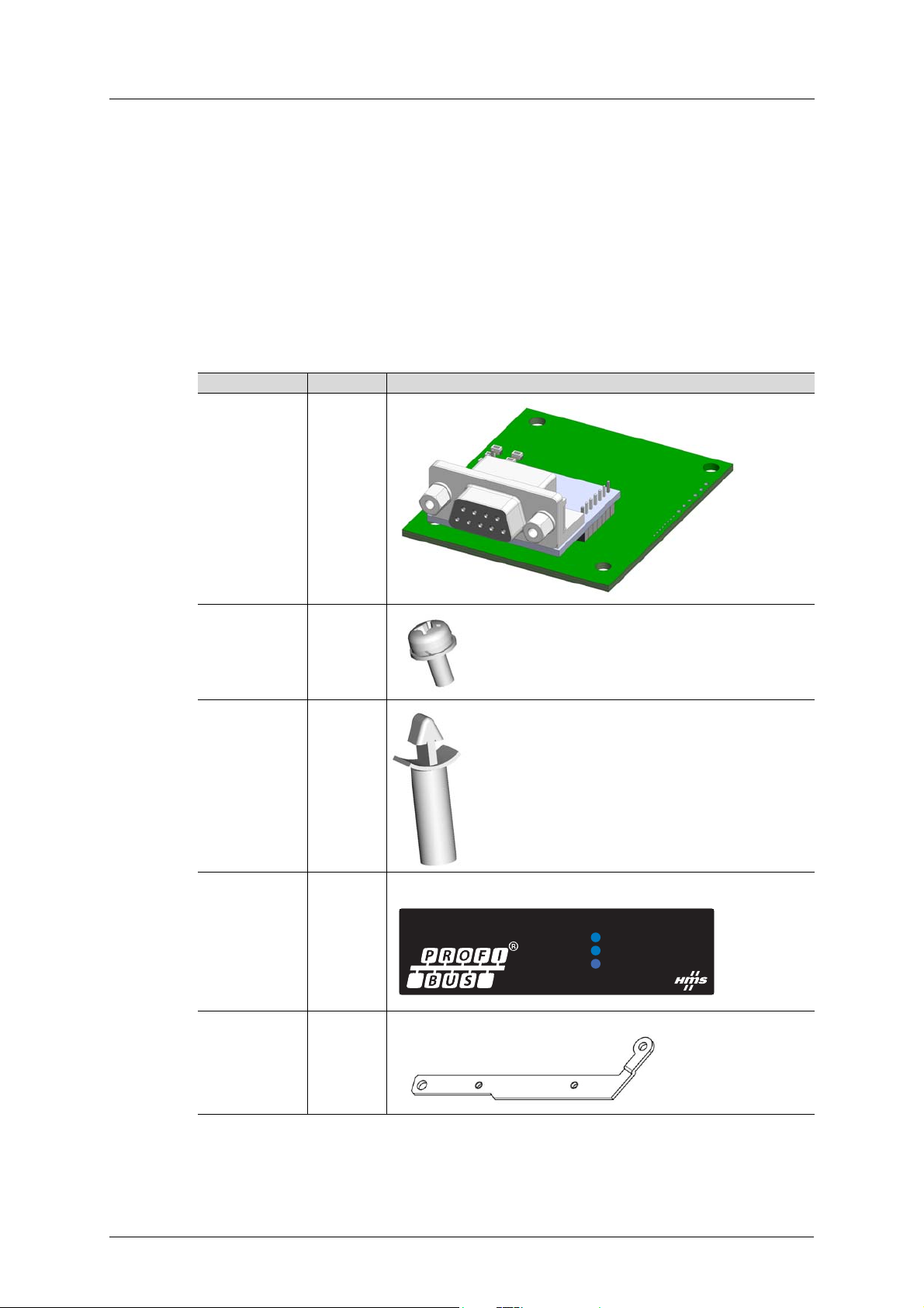
1.4.2 Component Overview
Included in the package are the following items.
Item No. of pcs
PCB board 1
M# x 6 mm screw 3
Board spacer 2
LED cover
Note: this picture
only shows the
label, not the
cover!
PE plate 1
1
6 Doc.Id. HMSI-216-127
Doc.Rev. 1.01
Page 17

Pre-Operation Instructions Environmental Specifications
1.5 Environmental Specifications
Item Specification
Operating Temperature -10º to +50º Celsius (ambient of the drive, non-freezing)
Storage Temperature -40º to +65º Celsius
Relative Humidity 93% non condensing
Vibration
Grounding Connected to inverter frame ground through the PE plate / isolated from
Power Supply Supplied from inverter
Cooling Method Self cooled
Communication Speed Up to 12 Mbit
Max acceleration amplitude: 10 m/s
Max displacement amplitude: 3 mm at 2 - 9 Hz
inverter control power common
The A8NPDPV1 interface is lead-free / RoHS-compliant.
2
at 9 - 200 Hz
A8NDPV1 PROFIBUS Option Board 7
Page 18

Environmental Specifications Pre-Operation Instructions
8 Doc.Id. HMSI-216-127
Doc.Rev. 1.01
Page 19
Installation Pre-installation Instructions
2. Installation
2.1 Pre-installation Instructions
WAR NIN G
To avoid damage to the inverter or plug-in option board, never install or remove a plug-in option board
while the inverter’s input power is on.
Make sure that the inverter’s power is OFF.
Physical installation of the option board is a two-step process. First, the card will be mounted
onto an available option connector on the inverter’s control board. Second, the card will be connected to the PROFIBUS network using a PROFIBUS cable.
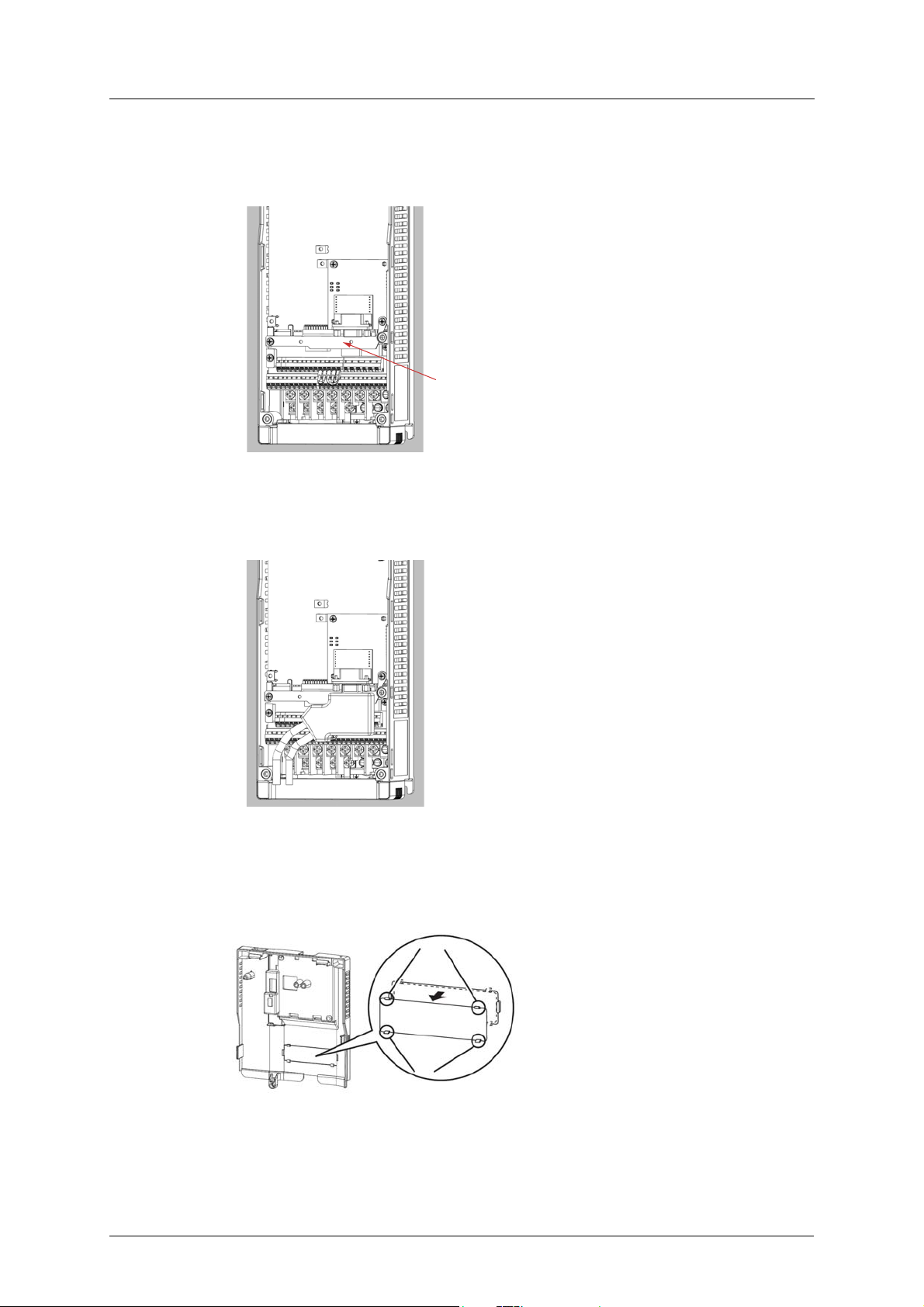
2.2 Installation Procedure
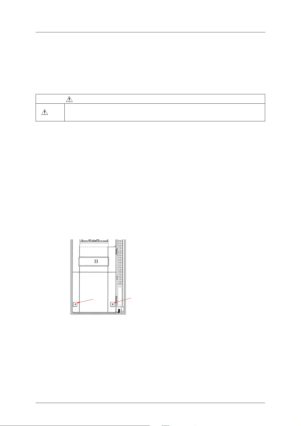
햲 Make sure that power is off.
햳 Remove both lids of the FR-A800 or FR-F800.
– Unscrew the two screws in the bottom corners of the inverter.
– Remove the lid covering the lower front of the inverter.
– Unscrew the screw in the bottom right corner of the lid covering the upper front of the in-
verter.
– Remove the lid.
A8NDPV1 PROFIBUS Option Board 9
Page 20
Installation Procedure Installation
1
2
3
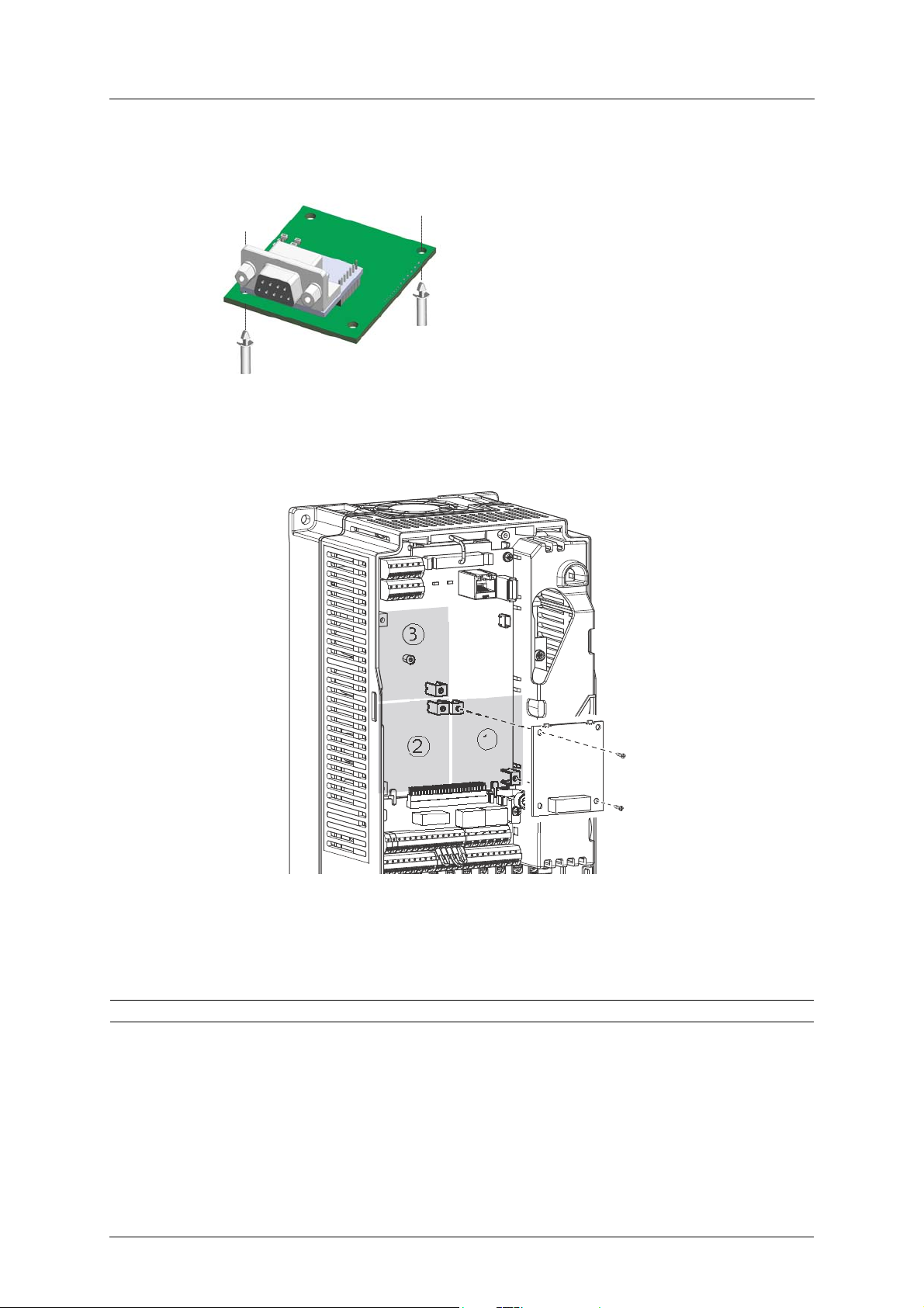
햴 Put the included studs in the holes at the right top and left bottom corners of the PCB.
햵 Position the A8NDPV1 PROFIBUS Option Board at the option slot 1 as shown in the image. This
is the only position that will allow network connectivity.
햶 Fasten the option board by tightening the included screws at the left top and right bottom
corners. The PE plate is attached along with the screw in the right bottom corner.
Note: Over-tightening the screws will damage the board.
10 Doc.Id. HMSI-216-127
Doc.Rev. 1.01
Page 21
Installation Installation Procedure
햷 Fasten the other end of the PE plate with another screw as shown in the picture.
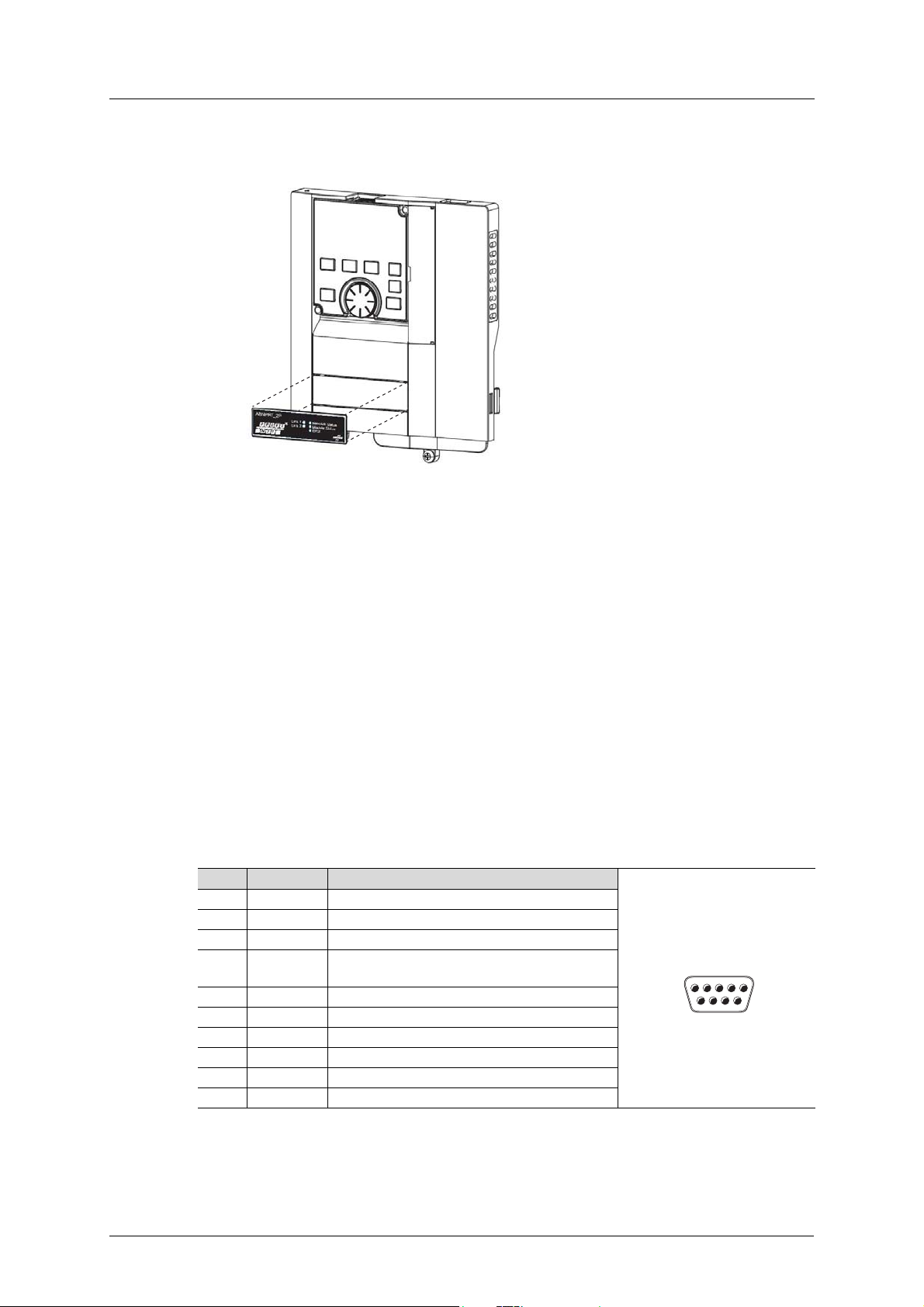
햸 Attach the network cable to the network connector on the option board.
햹 To fit the LED cover on the front cover of the drive, do as follows:
– Cut the bridges, using nippers, on the upper front cover.
A8NDPV1 PROFIBUS Option Board 11
Page 22
Network Connector (DSUB, female) Installation
51
69
female
female
– Snap the LED cover into the front cover of the drive.
햺 Fasten both front covers, top front cover first.
The option board is now mounted and power can be applied.
Removal
햲 Remove both lids of the FR-A800 or FR-F800 inverter.
햳 Remove the network cable.
햴 Remove the screws.
햵 Carefully remove the option board by lifting it straight up.
햶 Remove the board spacers.
햷 Replace the lids.
2.3 Network Connector (DSUB, female)
The option board provides connection to PROFIBUS through a female DSUB connector.
Pin Name Description
1NC
2NC
3 RxD/TxD-P Receive/Transmit data P; B-line
4 CNTR-P Repeater control signal (Direction control); RTS
signal
5 DGND Data ground (Reference voltage to VP)
6 VP Power supply; (PSV)
7NC
8 RxD/TxD-N Receive/Transmit data N; A-line
9NC
Shield PE
12 Doc.Id. HMSI-216-127
Doc.Rev. 1.01
Page 23

Installation LED Indicators
Network Status
Module Status
Error
A8NDPV1
2.4 LED Indicators
LED State Status
Network status Off Offline or no power
Green Online, data exchange
Green, 1 flash Online, clear
Red, 1 flash Module initialized, parametrization error.
Red, 2 flashes Module initialized, configuration error.
Red Fatal error. (Network status LED and Module status LED
will both be red.)
Module status Off Not initialized: no power or setup not finished
Green Operational
Green, 1 flash Module initialized, diagnostic event(s) present
Red Exception error: the option board is in the exception
state. If the Network status LED also indicates solid red, a
fatal error has occurred.
Error Off Communication with main unit is working without
problems.
Red Error in communication with main unit
Red, flashing (2 blinks) Invalid process data parameter mapped
Red, flashing (3 blinks) Too many process data parameters mapped
A8NDPV1 PROFIBUS Option Board 13
Page 24

LED Indicators Installation
14 Doc.Id. HMSI-216-127
Doc.Rev. 1.01
Page 25

Get Started Physical Installation
3. Get Started
All example programs described in this chapter are available for download from the MyMitsubishi website, see section “Download” on page 1 for a direct link.
3.1 Physical Installation
How to physically install the option board is described in “Installation Procedure” on page 9.
3.2 Download GSD file
Download the appropriate GSD file from the Mitsubishi Electric website, see section “Download”
on page 1 for a direct link.
3.3 Inverter setup
This chapter describes the first part of setting up a system using an A800 or F800 inverter controlled by Profibus. It assumes that the A8NDPV1 option card has been installed correctly, and all
inverter parameters are set to default values. This setup will be used for all get started example
programs.
The first step is to set the FDL address of the inverter Profibus slave. One way to do this is to set
parameter 1305 to the desired address, and parameter 1307 to 1. After restarting the inverter, the
option card will be available under the input address. The valid range for the FDL address is 0-125.
Parameter No. Va lue
1305 (1) FDL Address
1307 (1)
The next step is to change the operation mode of the inverter to network mode. Do this, by leaving the default setting of parameter 79 (0), and setting parameter 340 to 1. After restarting the
inverter, it should operate in network mode. For detailed settings, please refer to A800 or F800
manual.
A8NDPV1 PROFIBUS Option Board 15
Page 26
GX Works2 (Q-CPU) Telegram 1 example Get Started
3.4 GX Works2 (Q-CPU) Telegram 1 example
This chapter describes running the inverter through the A8NDPV1 Profibus option card using
GX Works 2 with a QCPU and QJ71PB92V Profibus Master. GX Configurator DP 7.10L or newer is
required to perform the setup.
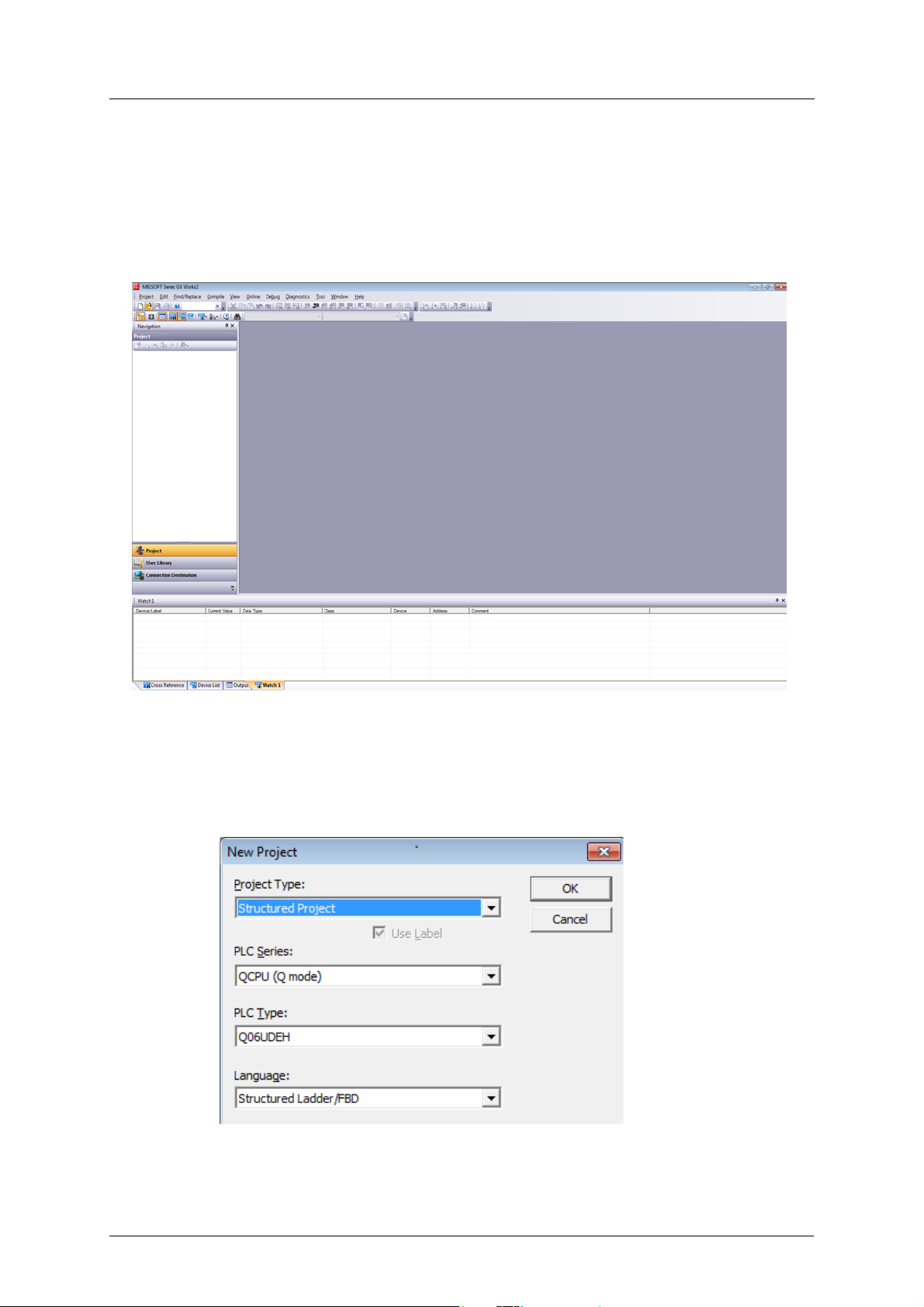
햲 Start with a new project.
햳 Select:
– Project type: Structured project;
– PLC Series: QCPU (Q mode);
– PLC type: select the cpu;
– Language: Structured Ladder/FBD.
16 Doc.Id. HMSI-216-127
Doc.Rev. 1.01
Page 27
Get Started GX Works2 (Q-CPU) Telegram 1 example
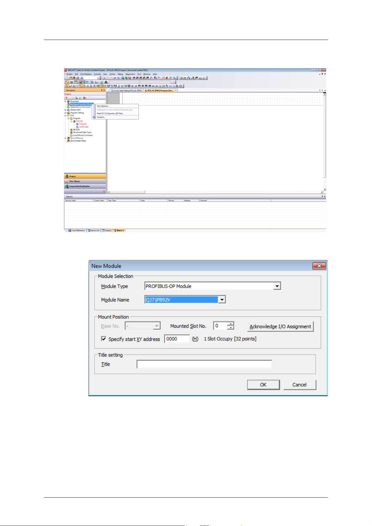
햴 Add a new Intelligent Function Module from the menu on the left (right click and select new):
햵 In the new window, click Module Type and select “PROFIBUS-DP Module”. Module Name
should be set to QJ71PB92V. Save this setting by clicking OK.
A8NDPV1 PROFIBUS Option Board 17
Page 28
GX Works2 (Q-CPU) Telegram 1 example Get Started
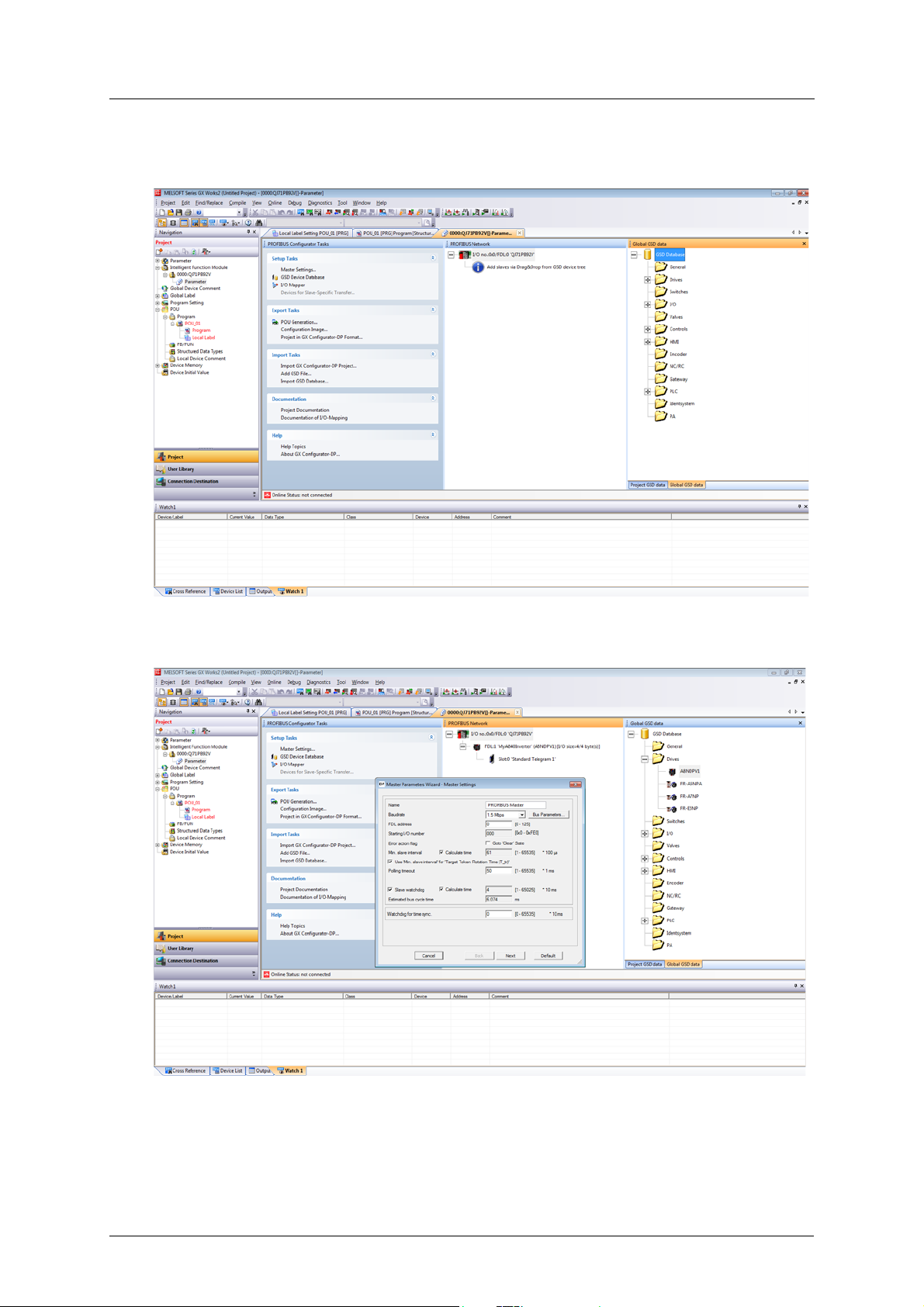
햶 The Profibus-DP module should be inserted into the Intelligent Function Module tree. Expand
it, and double click on Parameter. This should open the Profibus Configurator.
햷 First setup the Profibus Master. Double click on the master module (in the screenshot visible
as “I/O no.:0x0 FDL:0 ‘QJ71PB92V’. This will bring up the “Master Parameters Wizard”.
햸 It is possible to change the Baudrate, FDL address and other settings as needed. For this tuto-
rial these settings will not be changed. Click Next to proceed.
18 Doc.Id. HMSI-216-127
Doc.Rev. 1.01
Page 29
Get Started GX Works2 (Q-CPU) Telegram 1 example
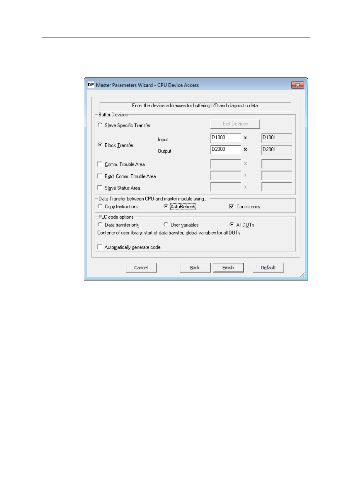
햹 On this screen the buffer devices, and data transfer between Profibus Master and CPU can be
changed. For this tutorial use AutoRefresh with Consistency. Click Finish to save settings and
close this wizard.
A8NDPV1 PROFIBUS Option Board 19
Page 30
GX Works2 (Q-CPU) Telegram 1 example Get Started
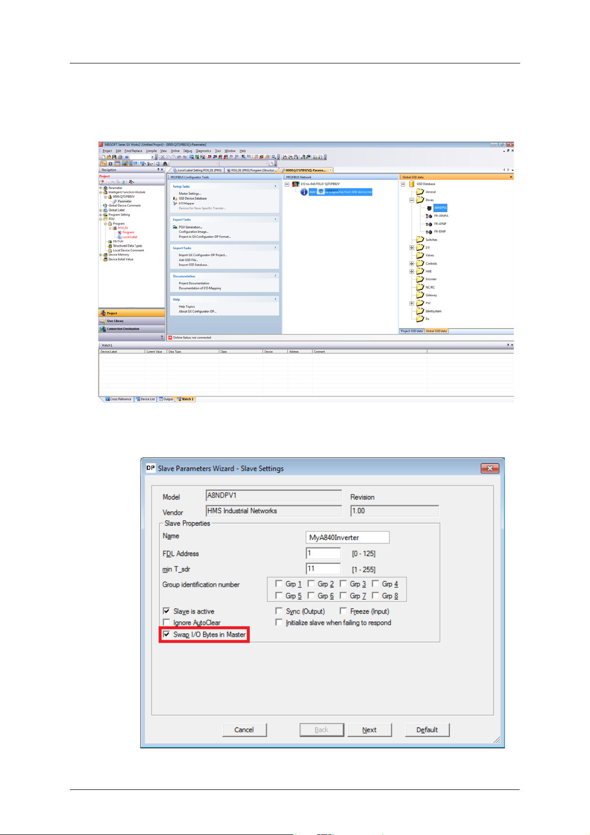
햺 In the Global GSD data section, expand drives and search for A8NDPV1. If it is not available,
right click and select Add GSD File. Search for the GSD File on the drive (included with this
manual), afterwards the A8NDPV1 should appear under drives. Drag this option to the Profibus Master, like on the screenshot.
The “Slave Parameters Wizard” should be shown. Enter a name, select 1 for FDL Address, and
make sure to select “Swap I/O Bytes in Master”. All other settings can remain as default. Click
Next to proceed.
20 Doc.Id. HMSI-216-127
Doc.Rev. 1.01
Page 31

Get Started GX Works2 (Q-CPU) Telegram 1 example
햻 Select the communication protocol used to communicate with the option card. For this tuto-
rial use “Standard Telegram 1”. Drag this option from the “Available Slave Modules” to “Project Slave Modules”. The A8NDPV1 supports only one module.
The result should be:
A8NDPV1 PROFIBUS Option Board 21
Page 32

GX Works2 (Q-CPU) Telegram 1 example Get Started
햽 Click Next to proceed. No changes are required on this screen, after clicking Next proceed to
the final screen and click Finish. The configured Profibus Slave should appear in the Profibus
Network window, like below.
햾 From the configurator’s left menu select POU Generation. This will create the user libraries
that can be used to control the inverter.
22 Doc.Id. HMSI-216-127
Doc.Rev. 1.01
Page 33

Get Started GX Works2 (Q-CPU) Telegram 1 example
햿 From the GX Works 2 Navigation window, expand Program settings. There should be two
tasks under “No Execution Type” – MAIN and PROFIBUS. Drag both tasks to “Scan Program” to
allow them to execute.
A8NDPV1 PROFIBUS Option Board 23
Page 34

GX Works2 (Q-CPU) Telegram 1 example Get Started
헀 The POU Generation creates a library containing global variable definitions. The global label
name conflicts with the project global label name setup by default in GX Works 2. In order to
avoid conflict, change the name of the project global label from “Global1” to “Global”. If this
is not done, an error will occur upon compilation.
헁 The Profibus controller is setup and ready to run after compilation and write to the PLC. Pro-
ceed to write the program to get the inverter running under a set frequency.
헂 Go to the User Library section, select the library generated by Profibus configurator and ex-
pand Global Label section. Double click on the global variables “Global1”. Take note of the
name of the global variables representing the input and output parameters to the inverter
Profibus controller. In this case it should be “vHA0_input” and “vHA0_output”. Both are an array of two words containing:
24 Doc.Id. HMSI-216-127
Doc.Rev. 1.01
Page 35

Get Started GX Works2 (Q-CPU) Telegram 1 example
– For vHA0_input: [0]=ZSW1, [1]=NIST_A.
– For vHA0_output: [0]=STW1, [1]=NSOLL_A.
헃 Return to the project section. From the MAIN Task, select the Program of POU_01. This Pro-
gram should be blank, this is where the example user program will be written.
A8NDPV1 PROFIBUS Option Board 25
Page 36

GX Works2 (Q-CPU) Telegram 1 example Get Started
General State Diagram
Power supply ON
S1: Switching ON Inhibited
ZSW1 bit 6 = true; 0, 1, 2 = false
OFF
AND No Coast Stop
AND No Quick Stop
STW1 bit 0 = fals e AND bit 1 = true
AND bit 2 = true
Coast Stop
OR Quick Stop
STW1 bit1 = false
OR bit 2 = false
S4: Operation
ZSW1 bit 0, 1, 2 = true; 6 = fa lse
ramp stop
quick stop
Coast Stop
STW1 bit 1 = fal se
Standstill detected
OR
Disable Operation
STW1 bit 3 = false
S5: Switching OFF
ZSW1 bit 0,1 = true,
bit 2,6 = false
Quick Stop
STW1 bit 2 = false
ON
STW1 bit 0 = true
OFF
STW1 bit 0 = false
Quick Stop
STW1 bit 2 = fal se
Disable Operation
STW1 bit 3 = false
Enable Operation
STW1 bit 3 = true
S3: Switched ON
ZSW1 bit 0, 1 = true; 2, 6 = fa lse
S2: Ready for Switching ON
ZSW1 bit 0 = true; 1, 2, 6 = false
Standstill
detected OR
Disable Operation
STW1 bit 3 = fal se
Coast Stop
STW1 bit 1 = false
ON
STW1 bit 0 = tr ue
OFF
STW1 bit 0 = false
Coast Stop
OR Quick Stop
STW1 bit1 = false
OR bit 2 = false
Coast Stop
STW1 bit 1 = fal se
accelerate with
Pr. 7 speed
coast stop
accelerate
with Pr. 7
speed
decelerate
with Pr. 8
speed
decelerate with
Pr. 1103 speed
쐌쐌쐌:1st priority
쐌쐌:2nd priority
쐌:3rd priority
헄 After powering up the inverter and Profibus master, connection will be established. Expect to
see bit 6 (Switching on inhibated) set in ZSW1. Below is a simplified state diagram, dependent
on control word 1 (STW1).
Control Word 1 (STW1) description
State / Bit combination Bit 10 Bit 7 Bit 3 Bit 2 Bit 1 Bit 0
Description
Control By
PLC
Switching on Inhibited - - - - 0 -
Ready To Switch On---11-
Switched On ---111
---0--
Operation - - 1 1 1 1
Rotation 1- 1111
Fault reset - 0 =>1 - - - -
26 Doc.Id. HMSI-216-127
Set both No Coast Stop and No Quick Stop to reset the Switching On Inhibited bit in ZSW1. To
do this set bits 1 and 2 in STW1, that is global label vHA0_output[0].
Faul t
acknowledge
Enable
operation
No quick
stop
No coast
stop
On
Doc.Rev. 1.01
Page 37

Get Started GX Works2 (Q-CPU) Telegram 1 example
Input the following ladder block to allow the inverter to enter “Ready For Switching On” status, after connection is established, and initialization command is given (M0).
헅 This initialization will result in setting bit 0 in ZSW1 (Ready To Switch On). It is now possible to
switch on the inverter, and start operation. To do this, enable bits 0 (ON/Off), 3 (enable operation), and 10 (Control By PLC) of STW1; while leaving bits 1 and 2 enabled.
At this moment it is also possible to set the desired rotation frequency. Assuming the motor
is rated for 50 Hz (inverter parameter 3) and a frequency of 10 Hz is requested, set 20% of the
rated motor speed to achieve this frequency. The value in Profidrive to allow full power is
16384, so setting 20% of this value (3276,8 round to 3277) will give the expected result. This
value shall be set in NSOLL_A.
Add the following ladder block to enable rotation command after initialization, and giving rotation command (M1).
헆 Finally add the code to stop the drive, when M1 is reset. In a new ladder block, check whether
the first 3 bits of ZSW1 are ON. This condition means that the drive is in operation mode. If this
condition is met, and M1 is not ON, reset the set point speed to zero, and set STW1 as 6.
A8NDPV1 PROFIBUS Option Board 27
Page 38

GX Works2 (Q-CPU) Telegram 1 example Get Started
21
Compile, and write the program and parameters to the PLC. After resetting the PLC, and powering up the inverter, set bits M0 and M1 to get the inverter running. Be sure to select the intelligent function module, like on the screenshot below.
28 Doc.Id. HMSI-216-127
Doc.Rev. 1.01
Page 39

Get Started GX Works2 (Q-CPU) Telegram 102 example
3.5 GX Works2 (Q-CPU) Telegram 102 example
This chapter describes running the inverter through the A8NDPV1 Profibus option card using
GX Works 2 with a QCPU and QJ71PB92V Profibus Master. First perform the setup using
telegram 1.
햲 Enter the Profibus Configurator and double click on the inverter to bring up the Slave Param-
eters Wizard. Click Next to proceed.
A8NDPV1 PROFIBUS Option Board 29
Page 40

GX Works2 (Q-CPU) Telegram 102 example Get Started
햳 Select “Standard Telegram 1” in the Project Slave Modules section. Click the red ‘x’ above this
section to clear this slot.
햴 From the Available Slave Modules, drag “Telegram 102 (Custom)” to the Project Slave Mod-
ules section. Click Next to proceed.
30 Doc.Id. HMSI-216-127
Doc.Rev. 1.01
Page 41

Get Started GX Works2 (Q-CPU) Telegram 102 example
햵 From the “select module” dropdown, select slot 0: Telegram 102 (Custom). It is now possible
to setup the input and outputs of the telegram. There are 18 inputs and outputs used in this
telegram, one of each is reserved for control/status word (leaving 17 inputs/outputs free for
custom setup).
A8NDPV1 PROFIBUS Option Board 31
Page 42

GX Works2 (Q-CPU) Telegram 102 example Get Started
햶 The setup of the telegram is done by entering signal/parameter numbers into the right col-
umn. All monitor data can be viewed as input, and some of the profile parameters as input/
output. Please keep in mind, that not all parameters can be accessed via cyclic communication. The PROFIdrive parameter numbers (PNUs) available for use are listed in the Data Exchange subchapters 7.1to 7.4. An example setup is provided:
Slot Description PNU
Output PZD/2 Speed set point 14317
Input PZD/2 Actual speed set point 14319
Input PZD/3 Output frequency 9193
Input PZD/4 Output voltage 9195
Input PZD/5 Actual operation time 9215
32 Doc.Id. HMSI-216-127
Doc.Rev. 1.01
Page 43

Get Started GX Works2 (Q-CPU) Telegram 102 example
햷 Click Next, and Finish to proceed. Complete the POU Generation, rebuild the project, and
write it to the PLC. The additional monitor data can be viewed in the appropriate position of
the vHA0_input array.
A8NDPV1 PROFIBUS Option Board 33
Page 44

GX Works2 (Q-CPU) Acyclic communication example Get Started
3.6 GX Works2 (Q-CPU) Acyclic communication example
This chapter describes using acyclic communication through the A8NDPV1 Profibus option card
using GX Works 2 with a QCPU and QJ71PB92V Profibus Master. It contains examples of reading
and writing individual parameters, as well as arrays. First perform the setup using telegram 1.
The process of acyclic communication parameter read consists of a write request, and a response
read. For details please refer to the Acyclic Data Exchange subchapter 7.7. These operations are
done using libraries supplied with the QJ71PB92V module (lib_dpv1). To perform acyclic communication without this library, please refer to the Simple Ladder example (chapter “GX Works2 (QCPU) Simple Ladder Acyclic communication example” on page 54).
3.6.1 Reading a parameter (Sequence 1)
Creating the request
Start by preparing the content for the parameter read request. The data request has the following
format:
Byte no. Description Value
0Request ID0x01
1Request reference0x01-0xFF
2No. of parameters0x01
3DO-ID0x01
4 No. of elements 0x00
5 Attribute value 0x10 (value attribute)
6-7 Parameter number Byte swapped PNU
Request reference is any valid number, this value is mirrored back in the response and can be
used to distinguish multiple requests. The parameter number needs to be byte swapped(the
SWAP instruction can be used to swap the lower and higher byte of a word).
In the code below requestParameterNo contains the unswapped parameter number, while re-
questParameterNoBS contains the byte swapped version. The content of the parameter request(DataToWrite), and the request to perform it (StartWrite), are shown in the screenshot
below:
34 Doc.Id. HMSI-216-127
Doc.Rev. 1.01
Page 45

Get Started GX Works2 (Q-CPU) Acyclic communication example
Proceed to issue the actual request using a function block from the lib_dpv1 library. Pick any
Dpv1WriteCh* function block, using different channels allows for simultaneous communication
to multiple slaves.
Receiving the response
If the request is completed successfully (bit wDone is ON), then perform a response read after a
delay of 500ms. Due to the nature of Profidrive acyclic communication, the response may not be
immediately available after execution of the request. Waiting a small amount of time significantly
increases the chance of receiving a response on the first try. Another solution is to keep executing
read requests, until a proper read request is received.
It should also be noted, that 240 bytes can always be read using the Dpv1ReadCh* function
blocks. This is the maximum allowed length of a response. In case of a shorter response, only the
available data will be read.
If the response is received successfully (bit rDone is ON), then the received data can be accessed
from DataRead. The format of a positive response is as follows:
Byte no. Description Value
0Request ID0x01
1 Request reference 0x01-0xFF (same as in request)
2No. of parameters0x01
3DO-ID0x01
4 No. of values 0x01
5 Format See data format type table
6-7 Parameter value Byte swapped parameter value
A8NDPV1 PROFIBUS Option Board 35
Page 46

GX Works2 (Q-CPU) Acyclic communication example Get Started
Extract the parameter value from DataRead, and byte swap it to receive the actual value:
In case of a negative response, the format is as follows:
Byte no. Description Value
0Request ID0x81
1 Request reference 0x01-0xFF (same as in request)
2No. of parameters0x01
3DO-ID0x01
4 No. of values 0x01
5 Format 0x44 (error)
6-7 Error value Byte swapped error value (see
error table)
Executing example requests
After compiling the program, and writing it to the PLC, it is possible to execute parameter read
requests. First, get the inverter running by setting bits M0 and M1. Now read the actual frequency
by writing PNU 9193 to requestParameterNo and setting bit requestParameter. The result should
be a value of 1000 in parameterValue which corresponds to 10Hz. The PROFIdrive parameter
numbers (PNUs) available for use are listed in the Data Exchange subchapters 7.1to 7.4.
36 Doc.Id. HMSI-216-127
Doc.Rev. 1.01
Page 47

Get Started GX Works2 (Q-CPU) Acyclic communication example
Try reading an inverter parameter, for example the FDL address of the inverter (parameter 1305
+ 5096 offset = PNU 6401). The expected result is 1. It is possible to read any inverter parameter
in this way.
3.6.2 Reading an array of parameters (Sequence 3)
Certain parameters are available in the form of an array. It is possible to access individual elements of the array be changing the subindex. It is also possible to retrieve multiple elements of
the array by executing sequence 3. This requires only changing byte no. 4 of the request (No. of
values) to the amount of array values wanted. The response will contain additional parameter
values added to the end of the response data.
Creating the request
For this example all 5 array elements of PNU 964 (Device identification) will be requested. Modify
the parameter request as described above:
A8NDPV1 PROFIBUS Option Board 37
Page 48

GX Works2 (Q-CPU) Acyclic communication example Get Started
Reading the response
Modify the code reading the response data, to read all 5 elements, and byte swap each one. An
example procedure how to do this is shown below. The byte-swapped elements will be available
in the parameterValueArray.
Executing example request
After executing a request, the response data is available in the parameterValueArray variable.
38 Doc.Id. HMSI-216-127
Doc.Rev. 1.01
Page 49

Get Started GX Works2 (Q-CPU) Acyclic communication example
3.6.3 Changing parameters (Sequence 2)
Creating the request
The format of the write request is as follows:
Byte no. Description Value
0Request ID0x02
1Request reference0x01-0xFF
2No. of parameters0x01
3DO-ID0x01
4 No. of elements 0x00
5 Attribute value 0x10 (value attribute)
6-7 Parameter number Byte swapped PNU
8-9 Subindex (irrelevant) 0x00
10 No. of values 0x01
11 Format 0x06 (UINTEGER16 for all inverter
parameters)
See data format type table
12-13 Set value Byte swapped set value
Modify the ladder block preparing the content of the request.
Change the actual length of the write request. Change the length to 28 hex characters in the ladder block that executes the request.
A8NDPV1 PROFIBUS Option Board 39
Page 50

GX Works2 (Q-CPU) Acyclic communication example Get Started
Reading the response
The length of the expected read response is up to 8 bytes.
Finally modify the ladder block processing the response data. A positive response consists of just
4 bytes of data in the following format:
Byte no. Description Value
0Request ID0x02
1 Request reference 0x01-0xFF (same as in request)
2No. of parameters0x01
3DO-ID0x01
In case of a negative response, the format is as follows:
Byte no. Description Value
0Request ID0x82
1 Request reference 0x01-0xFF (same as in request)
2No. of parameters0x01
3DO-ID0x01
4 No. of values 0x01
5 Format 0x44 (error)
6-7 Error value Byte swapped error value (see
error table)
After a successful response is received (bit rDone is ON), check the length of the received response to determine, whether the parameter write request was processed successfully. If the
length (rDataLengthRead) is equal to 4, set a bit indicating a successful parameter write. If this is
not true, a bit indicating parameter write failure shall be set, and the error code shall be extracted
to variable parameterWriteErrorCode.
40 Doc.Id. HMSI-216-127
Doc.Rev. 1.01
Page 51

Get Started GX Works2 (Q-CPU) Acyclic communication example
Executing example requests
To perform a parameter write, set the PNU of the parameter to change in requestParameterNo. As
an example, to change parameter 15 (Jog frequency), add the offset 5096 and write the result to
this variable. Set variable requestParameterValue to the requested value. The value that will be
set, will be the output of multiplication of the set value, and the minimum setting increments, as
according to the parameter list in the inverter manual. For parameter 15, the minimum setting
increment is 0.01Hz. If a jog frequency of 5Hz is requested, set requestParameterValue to 500. Finally execute the request by setting bit requestParameter to ON. A successful write will result in
setting of the parameterWriteSuccess bit.
Test receiving a negative response, by trying to write an out of range value. After trying to write
0xFFFF as the value of parameter 15, a negative response with error code 0x02
(LOW_OR_HIGH_LIMIT_EXCEEDED) will be received, which is the expected behavior.
A8NDPV1 PROFIBUS Option Board 41
Page 52

GX Works2 (Q-CPU) Simple Ladder Telegram 1 example Get Started
3.7 GX Works2 (Q-CPU) Simple Ladder Telegram 1 example
This chapter describes running the inverter through the A8NDPV1 Profibus option card using
GX Works 2 in Simple Ladder mode with a QCPU and QJ71PB92V Profibus Master. GX Configurator DP 7.10L or newer is required to perform the setup.
햲 Start with a new project in simple ladder mode. Select:
– Project type: Simple project;
– PLC Series: QCPU (Q mode);
– PLC type: select the cpu;
– Language: Ladder.
햳 Add a new Intelligent Function Module from the menu on the left (right click and select new):
42 Doc.Id. HMSI-216-127
Doc.Rev. 1.01
Page 53

Get Started GX Works2 (Q-CPU) Simple Ladder Telegram 1 example
햴 In the new window, click Module Type and select “PROFIBUS-DP Module”. Module Name
should be set to QJ71PB92V. Save this setting by clicking OK.
햵 The Profibus-DP module should be inserted into the Intelligent Function Module tree. Expand
it, and double click on Parameter. This should open the Profibus Configurator.
A8NDPV1 PROFIBUS Option Board 43
Page 54

GX Works2 (Q-CPU) Simple Ladder Telegram 1 example Get Started
햶 First setup the Profibus Master. Double click on the master module (in the screenshot visible
as “I/O no.:0x0 FDL:0 ‘QJ71PB92V’. This will bring up the “Master Parameters Wizard”.
햷 The Baudrate, FDL address and other settings can be changed as needed. For this tutorial
these settings will not be changed. Click Next to proceed.
햸 On this screen it is possible to change the buffer devices, and data transfer between Profibus
Master and CPU. For this tutorial use AutoRefresh with Consistency. Click Finish to save settings and close this wizard.
44 Doc.Id. HMSI-216-127
Doc.Rev. 1.01
Page 55

Get Started GX Works2 (Q-CPU) Simple Ladder Telegram 1 example
햹 In the Global GSD data section, expand drives and search for A8NDPV1. If it is not available,
right click and select Add GSD File. Search for the GSD File on the drive (included with this
manual), afterwards the A8NDPV1 should appear under drives. Drag this option to the Profibus Master, like on the screenshot.
The “Slave Parameters Wizard” should now be shown. Enter a name, select 1 for FDL Address,
and make sure to select “Swap I/O Bytes in Master”. All other settings can remain as default.
Click Next to proceed.
A8NDPV1 PROFIBUS Option Board 45
Page 56

GX Works2 (Q-CPU) Simple Ladder Telegram 1 example Get Started
햺 Select the communication protocol used to communicate with the option card. For this tuto-
rial use “Standard Telegram 1”. Drag this option from the “Available Slave Modules” to “Project Slave Modules”. The A8NDPV1 supports only one module.
The result should be:
46 Doc.Id. HMSI-216-127
Doc.Rev. 1.01
Page 57

Get Started GX Works2 (Q-CPU) Simple Ladder Telegram 1 example
햻 Click Next to proceed. No changes are required on this screen. After clicking Next proceed to
the final screen and click Finish. The configured Profibus Slave should appear in the Profibus
Network window, like below.
햽 As of now, the Profibus controller is setup and ready to run after compilation and write to the
PLC. Proceed to write the program to get the inverter running under a set frequency. Below
is a table of PLC devices and their corresponding meaning in PROFIdrive
Device Description
D1000 (input) ZSW1
D1001 (input) NIST_A
D2000 (output) STW1
D2001 (output) NSOLL_A
햾 Start the ladder program by initializing Profibus communication.
A8NDPV1 PROFIBUS Option Board 47
Page 58

GX Works2 (Q-CPU) Simple Ladder Telegram 1 example Get Started
햿 After powering up the inverter and Profibus master, connection will be established. Expect to
see bit 6 (Switching on inhibated) set in ZSW1. Refer to the simplified state diagram (chapter
GX Works2 (Q-CPU) Telegram 1 example), dependent on control word 1 (STW1).
Control Word 1 (STW1) description
State / Bit combination Bit 10 Bit 7 Bit 3 Bit 2 Bit 1 Bit 0
Description
Switching on Inhibited - - - - 0 -
Ready To Switch On---11-
Switched On ---111
Operation - - 1 1 1 1
Rotation 1- 1111
Fault reset - 0=>1 - - - -
Control By
PLC
---0--
Faul t
acknowledge
Enable
operation
No quick
stop
No coast
stop
On
Both No Coast Stop and No Quick Stop need to be set to reset the Switching On Inhibited bit
in ZSW1. To do this set bits 1 and 2 in STW1, that is D2000.
Input the following ladder to allow the inverter to enter “Ready For Switching On” status, after
connection is established, and initialization command is given (M0).
헀 This initialization will result in setting bit 0 in ZSW1 (Ready To Switch On). Switch on the in-
verter, and start operation. To do this enable bits 0 (ON/Off), 3 (enable operation), and 10
(Control By PLC) of STW1; while leaving bits 1 and 2 enabled.
헁 At this moment it is also possible to set the desired rotation frequency. Assuming the motor
is rated for 50 Hz (inverter parameter 3) and a frequency of 10 Hz is requested, set 20% of the
rated motor speed to achieve this frequency. The value in Profidrive to allow full power is
16384, so setting 20% of this value (3276,8 round to 3277) will give the expected result. This
value shall be set in NSOLL_A (D2001).
Add the following ladder block to enable rotation command after initialization, and giving rotation command (M1).
48 Doc.Id. HMSI-216-127
Doc.Rev. 1.01
Page 59

Get Started GX Works2 (Q-CPU) Simple Ladder Telegram 1 example
헂 Finally add the code to stop the drive, when M1 is reset. Check whether the first 3 bits of ZSW1
are ON. This condition means that the drive is in operation mode. If this condition is met, and
M1 is not ON, reset the set point speed to zero, and set STW1 as 6.
헃 Compile, and write the program and parameters to the PLC. Be sure to select the intelligent
function module, like on the screenshot below.
After resetting the PLC, and powering up the inverter set bits M0 and M1 to get the inverter
up and running.
A8NDPV1 PROFIBUS Option Board 49
Page 60

GX Works2 (Q-CPU) Simple Ladder Telegram 102 example Get Started
3.8
GX Works2 (Q-CPU) Simple Ladder Telegram 102 example
This chapter describes running the inverter through the A8NDPV1 Profibus option card using
GX Works 2 in Simple Ladder mode with a QCPU and QJ71PB92V Profibus Master. First perform
the setup using telegram 1.
햲 Enter the Profibus Configurator and double click on the inverter to bring up the Slave Param-
eters Wizard. Click Next to proceed.
햳 Select “Standard Telegram 1” in the Project Slave Modules section. Click the red ‘x’ above this
section to clear this slot.
50 Doc.Id. HMSI-216-127
Doc.Rev. 1.01
Page 61

Get Started GX Works2 (Q-CPU) Simple Ladder Telegram 102 example
햴 From the Available Slave Modules, drag “Telegram 102 (Custom)” to the Project Slave Mod-
ules section. Click Next to proceed.
햵 From the “select module” dropdown, select slot 0: Telegram 102 (Custom). It is now possible
to setup the input and outputs of the telegram. There are 18 inputs and outputs used in this
telegram, one of each is reserved for control/status word (leaving 17 inputs/outputs free for
custom setup).
햶 The setup of the telegram is done by entering signal/parameter numbers into the right col-
umn. All monitor data can be viewed as input, and some of the profile parameters as input/
output. Please keep in mind, that not all parameters can be accessed via cyclic communication. The PROFIdrive parameter numbers (PNUs) available for use are listed in the Data Exchange subchapters 7.1to 7.4. Below is an example setup:
Slot Description PNU
Output PZD/2 Speed set point 14317
Input PZD/2 Actual speed set point 14319
Input PZD/3 Output frequency 9193
Input PZD/4 Output voltage 9195
Input PZD/5 Actual operation time 9215
A8NDPV1 PROFIBUS Option Board 51
Page 62

GX Works2 (Q-CPU) Simple Ladder Telegram 102 example Get Started
52 Doc.Id. HMSI-216-127
Doc.Rev. 1.01
Page 63

Get Started GX Works2 (Q-CPU) Simple Ladder Telegram 102 example
햷 Click Next, and Finish to proceed. Save the project, and write it to the PLC. The additional mon-
itor data can be viewed in the appropriate buffer device. To view the devices that are occupied by Profibus, double click on the Profibus master to bring up the Master Parameters
Wizard and click Next. The buffer devices section displays which device addresses are occupied.
A8NDPV1 PROFIBUS Option Board 53
Page 64

GX Works2 (Q-CPU) Simple Ladder Acyclic communication example Get Started
3.9 GX Works2 (Q-CPU) Simple Ladder Acyclic communication example
This chapter describes using acyclic communication through the A8NDPV1 Profibus option card
using GX Works 2 in Simple Ladder mode with a QCPU and QJ71PB92V Profibus Master. It contains examples of reading and writing individual parameters. First perform the setup using telegram 1. For additional information refer to the QJ71PB92V manual.
The process of acyclic communication parameter read consists of a write request, and a response
read. For details please refer to the Acyclic Data Exchange subchapter 7.7.
3.9.1 Reading a parameter (Sequence 1)
Creating the request
The first part of the program should read the acceptance/completion status of the acyclic request. This can be done with the following code:
Prepare the content for the parameter read request. The data request has the following format:
Byte no. Description Value
0 Request ID 0x01
1 Request reference 0x01-0xFF
2 No. of parameters 0x01
3 DO-ID 0x01
4 No. of elements 0x00
5 Attribute value 0x10 (value attribute)
6-7 Parameter number Byte swapped PNU
54 Doc.Id. HMSI-216-127
Doc.Rev. 1.01
Page 65

Get Started GX Works2 (Q-CPU) Simple Ladder Acyclic communication example
Request reference is any valid number, this value is mirrored back in the response and can be
used to distinguish multiple requests. The parameter number needs to be byte swapped (the
SWAP instruction can be used to swap the lower and higher byte of a word). Below is an example
on how to prepare the request data:
The code above (after executing the write to the Profibus slave) will return information regarding
the success of making the request, not the actually requested data. Before making the actual request, prepare the data for the read request:
A8NDPV1 PROFIBUS Option Board 55
Page 66

GX Works2 (Q-CPU) Simple Ladder Acyclic communication example Get Started
In the program there is a delay of 500ms between receiving confirmation of the write request,
and executing the read request. Due to the nature of Profidrive acyclic communication, the response may not be immediately available after execution of the request. Waiting a small amount
of time significantly increases the chance of receiving a response on the first try. Another solution
is to keep executing read requests, until a proper read request is received.
Finally include the code that executes the prepared request:
56 Doc.Id. HMSI-216-127
Doc.Rev. 1.01
Page 67

Get Started GX Works2 (Q-CPU) Simple Ladder Acyclic communication example
Receiving the response
The requests are completed after buffer memory bit G25120.0 turns ON. Successful completion
is achieved if buffer memory G25121 is equal to 0xA400 for read request and 0xA401 for write request.
After the write request is executed successfully, expect G25121 (D3000) to equal 0xA401. Set M11
to continue the sequence and issue the read request. This time a value of 0xA400 means a successful execution. The received data starts from buffer memory address G25127 (D3006). In buffer memory G25121-25126 (D3000-D3005) data regarding the acyclic request is held, as described
in the QJ71PB92V manual. The format of a positive response is as follows:
Byte no. Description Value
0 Request ID 0x01
1 Request reference 0x01-0xFF (same as in request)
2 No. of parameters 0x01
3 DO-ID 0x01
4 No. of values 0x01
5 Format See data format type table
6-7 Parameter value Byte swapped parameter value
A8NDPV1 PROFIBUS Option Board 57
Page 68

GX Works2 (Q-CPU) Simple Ladder Acyclic communication example Get Started
In case of a negative response, the format is as follows:
Byte no. Description Value
0 Request ID 0x81
1 Request reference 0x01-0xFF (same as in request)
2 No. of parameters 0x01
3 DO-ID 0x01
4 No. of values 0x01
5 Format 0x44 (error)
6-7 Error value Byte swapped error value (see
error table)
The parameter value (or error value) can be therefore read from D3008. This value is byte
swapped and saved to address D3502.
Executing example requests
In the code above the following devices are used:
Device Description
M5 Perform acyclic request
M10 Trigger sequence / Prepare write request
M11 Continue sequence / Prepare read request
M100 – M108 Acceptance/completion status
D3000 Acyclic response code
D3001 – D3013 PROFIdrive response data (byte swapped)
D3500 PNU to read
D3501 Byte-swapped PNU no.
D3502 PNU value
After compiling the program, and writing it to the PLC, it is possible to execute parameter read
requests. First, get the inverter running by setting bits M0 and M1. Now read the actual frequency
by writing PNU 9193 to D3500 and setting bit M10. The result should be a value of 1000 in 3502
which corresponds to 10Hz. The PROFIdrive parameter numbers (PNUs) available for use are listed in the Data Exchange subchapters 7.1 to 7.4.
58 Doc.Id. HMSI-216-127
Doc.Rev. 1.01
Page 69

Get Started GX Works2 (Q-CPU) Simple Ladder Acyclic communication example
3.9.2 Changing parameters (Sequence 2)
Creating the request
The idea of executing a change (write) of a PNU is the same as reading one. The only difference
is the change of the data request / response.
The format of the write request is as follows:
Byte no. Description Val ue
0Request ID 0x02
1Request reference0x01-0xFF
2 No. of parameters 0x01
3DO-ID 0x01
4 No. of elements 0x00
5 Attribute value 0x10 (value attribute)
6-7 Parameter number Byte swapped PNU
8-9 Subindex (irrelevant) 0x00
10 No. of values 0x01
11 Format 0x06 (UINTEGER16 for all inverter parameters)
See data format type table
12-13 Set value Byte swapped set value
A8NDPV1 PROFIBUS Option Board 59
Page 70

GX Works2 (Q-CPU) Simple Ladder Acyclic communication example Get Started
Modify the content of the write request.
60 Doc.Id. HMSI-216-127
Doc.Rev. 1.01
Page 71

Get Started GX Works2 (Q-CPU) Simple Ladder Acyclic communication example
Modify the read request:
Modify the execution of the request:
A8NDPV1 PROFIBUS Option Board 61
Page 72

GX Works2 (Q-CPU) Simple Ladder Acyclic communication example Get Started
Reading the response
A positive response consists of just 4 bytes of data in the following format:
Byte no. Description Value
0 Request ID 0x02
1 Request reference 0x01-0xFF (same as in request)
2 No. of parameters 0x01
3 DO-ID 0x01
In case of a negative response, the format is as follows:
Byte no. Description Value
0 Request ID 0x82
1 Request reference 0x01-0xFF (same as in request)
2 No. of parameters 0x01
3 DO-ID 0x01
4 No. of values 0x01
5 Format 0x44 (error)
6-7 Error value Byte swapped error value (see
error table)
The requests are completed after buffer memory bit G25120.0 turns ON. Successful completion
is achieved if buffer memory G25121 is equal to 0xA400 for read request and 0xA401 for write request. If the write request is executed successfully, the program will continue with the read request, and if this is also successful bit M12 will be set ON to process the response.
62 Doc.Id. HMSI-216-127
Doc.Rev. 1.01
Page 73

Get Started GX Works2 (Q-CPU) Simple Ladder Acyclic communication example
If a successful parameter write request was performed (request ID = 0x02), bit M14 shall turn on.
In case of a failure (request ID = 0x82) bit M13 will be ON, and the error code will be stored in
D3504.
A8NDPV1 PROFIBUS Option Board 63
Page 74

GX Works2 (Q-CPU) Simple Ladder Acyclic communication example Get Started
Executing example requests
In this program the following devices are used:
Device Description
M5 Perform acyclic request
M10 Trigger sequence / Prepare write request
M11 Continue sequence / Prepare read request
M13 Parameter write failed
M14 Parameter write success
M100 – M108 Acceptance/completion status
D3000 Acyclic response code
D3001 – D3013 PROFIdrive response data
D3500 PNU to change
D3501 Byte-swapped PNU no.
D3502 PNU value to set
D3503 Byte-swapped PNU value to set
D3504 PROFIdrive error value
To perform a parameter write, set the PNU of the parameter to change in D3500. In order to
change parameter 15 (Jog frequency), add the offset 5096 and write the result to D3500. Set
D3502 to the requested value. The value that will be set, will be the output of multiplication of the
set value, and the minimum setting increments, as according to the parameter list in the inverter
manual. For parameter 15, the minimum setting increment is 0.01Hz. If a jog frequency of 5Hz is
requested, set D3502 to 500. Finally execute the request by setting bit M10 to ON. A successful
write will result in setting of the M14 bit.
Test receiving a negative response, by trying to write an out of range value. After trying to write
0xFFFF as the value of parameter 15, a negative response with error code 0x02
(LOW_OR_HIGH_LIMIT_EXCEEDED) will be received, which is the expected behavior.
64 Doc.Id. HMSI-216-127
Doc.Rev. 1.01
Page 75

Get Started GX Works2 (FX-CPU) Telegram 1 example
3.10 GX Works2 (FX-CPU) Telegram 1 example
This chapter describes running the inverter through the A8NDPV1 Profibus option card using
GX Works 2 (version 1.501X or newer) with a FXCPU and FX3U-64DP-M Profibus Master. GX Configurator DP 7.10L or newer is required to perform the setup.
햲 Start with a new project.
Select:
–Series: FXCPU;
– PLC type: Select the cpu;
– Project type: Structured project;
– Language: Structured Ladder/FBD.
햳 Add a new Special Module (Intelligent Function Module) from the menu on the left (right click
and select new):
A8NDPV1 PROFIBUS Option Board 65
Page 76

GX Works2 (FX-CPU) Telegram 1 example Get Started
햴 In the new window, click Module Type and select “PROFIBUS-DP Module”. Module Name
should be set to FX3U-64DP-M. Save this setting by clicking OK.
햵 The Profibus-DP module should be inserted into the Intelligent Function Module tree. Expand
it, and double click on Parameter. This should open the Profibus Configurator.
66 Doc.Id. HMSI-216-127
Doc.Rev. 1.01
Page 77

Get Started GX Works2 (FX-CPU) Telegram 1 example
햶 First setup the Profibus Master. Double click on the master module (in the screenshot visible
as “Slot:0x0/FDL:0 ‘FX3U-64DP-M”. This will bring up the “Master Parameters Wizard”.
햷 It is possible to change the Baudrate, FDL address and other settings as needed. For this tuto-
rial these settings will not be changed. Click Next to proceed.
A8NDPV1 PROFIBUS Option Board 67
Page 78

GX Works2 (FX-CPU) Telegram 1 example Get Started
햸 On this screen the buffer devices, and data transfer between Profibus Master and CPU can be
changed. For this tutorial use AutoRefresh with Consistency. Click Finish to save settings and
close this wizard.
68 Doc.Id. HMSI-216-127
Doc.Rev. 1.01
Page 79

Get Started GX Works2 (FX-CPU) Telegram 1 example
햹 In the Global GSD data section, expand drives and search for A8NDPV1. If it is not available,
right click and select Add GSD File. Search for the GSD File on the drive (included with this
manual), afterwards the A8NDPV1 should appear under drives. Drag this option to the Profibus Master, like on the screenshot.
The “Slave Parameters Wizard” should be shown. Enter a name, select 1 for FDL Address, and
make sure to select “Swap I/O Bytes in Master”. All other settings can remain as default. Click
Next to proceed.
A8NDPV1 PROFIBUS Option Board 69
Page 80

GX Works2 (FX-CPU) Telegram 1 example Get Started
햺 Select the communication protocol used to communicate with the option card. For this tuto-
rial use “Standard Telegram 1”. Drag this option from the “Available Slave Modules” to “Project Slave Modules”. The A8NDPV1 supports only one module.
The result should be:
70 Doc.Id. HMSI-216-127
Doc.Rev. 1.01
Page 81

Get Started GX Works2 (FX-CPU) Telegram 1 example
햻 Click Next to proceed. No changes are required on this screen, after clicking Next proceed to
the final screen and click Finish. The configured Profibus Slave should appear in the Profibus
Network window, like below.
햽 From the configurator’s left menu select POU Generation. This will create the user libraries
that can be used to control the inverter.
A8NDPV1 PROFIBUS Option Board 71
Page 82

GX Works2 (FX-CPU) Telegram 1 example Get Started
햾 The POU Generation creates a library containing global variable definitions. The global label
name conflicts with the project global label name setup by default in GX Works 2. In order to
avoid conflict, change the name of the project global label from “Global1” to “Global”. If this
is not done, an error will occur upon compilation.
햿 The Profibus controller is setup and ready to run after compilation and write to the PLC. Pro-
ceed to write the program to get the inverter running under a set frequency.
헀 Go to the User Library section, select the library generated by Profibus configurator and click
on the lock pad icon to unlock it.
72 Doc.Id. HMSI-216-127
Doc.Rev. 1.01
Page 83

Get Started GX Works2 (FX-CPU) Telegram 1 example
헁 Enter the global label definition file and modify the label names to your liking. To allow easy
following of this tutorial, please use the names like on the screenshot below:
헂 The data is defined as follows :
– For A800_In: [0] = ZSW1, [1] = NIST_A.
– For A800_Out: [0] = STW1, [1] = NSOLL_A.
A8NDPV1 PROFIBUS Option Board 73
Page 84

GX Works2 (FX-CPU) Telegram 1 example Get Started
헃 Return to the project section. From the MAIN Task, select the Program of POU_01. This Pro-
gram should be blank, this is where the example user program will be written.
헄 After powering up the inverter and Profibus master, connection will be established. Expect to
see bit 6 (Switching on inhibated) set in ZSW1. For details refer to chapter 7.5 "General State
Diagram"
Set both No Coast Stop and No Quick Stop to reset the Switching On Inhibited bit in ZSW1. To
do this set bits 1 and 2 in STW1, that is global label vHA0_output[0].
Input the following ladder block to allow the inverter to enter “Ready For Switching On” status, after connection is established, and initialization command is given (M0).
74 Doc.Id. HMSI-216-127
Doc.Rev. 1.01
Page 85

Get Started GX Works2 (FX-CPU) Telegram 1 example
헅 This initialization will result in setting bit 0 in ZSW1 (Ready To Switch On). It is now possible to
switch on the inverter, and start operation. To do this, enable bits 0 (ON/Off), 3 (enable operation), and 10 (Control By PLC) of STW1; while leaving bits 1 and 2 enabled.
At this moment it is also possible to set the desired rotation frequency. Assuming the motor
is rated for 50 Hz (inverter parameter 3) and a frequency of 10 Hz is requested, set 20% of the
rated motor speed to achieve this frequency. The value in Profidrive to allow full power is
16384, so setting 20% of this value (3276,8 round to 3277) will give the expected result. This
value shall be set in NSOLL_A.
Add the following ladder block to enable rotation command after initialization, and giving rotation command (M1).
헆 Finally add the code to stop the drive, when M1 is reset. In a new ladder block, check whether
the first 3 bits of ZSW1 are ON. This condition means that the drive is in operation mode. If this
condition is met, and M1 is not ON, reset the set point speed to zero, and set STW1 as 6.
A8NDPV1 PROFIBUS Option Board 75
Page 86

GX Works2 (FX-CPU) Telegram 1 example Get Started
21
Compile, and write the program and parameters to the PLC. Be sure to select the intelligent
function module, like on the screenshot below.
If this option is not visible, then the firmware on your FX3U-64DP-M module does not support
the new intelligent module function. Please upgrade the firmware, or download the module
setup using the standalone GX Configurator DP.
After resetting the PLC, and powering up the inverter, set bits M0 and M1 to get the inverter
running.
76 Doc.Id. HMSI-216-127
Doc.Rev. 1.01
Page 87

Get Started GX Works2 (FX-CPU) Telegram 102 example
3.11 GX Works2 (FX-CPU) Telegram 102 example
This chapter describes running the inverter through the A8NDPV1 Profibus option card using
GX Works 2 (version 1.501X or newer) with a FXCPU and FX3U-64DP-M Profibus Master.
햲 Enter the Profibus Configurator and double click on the inverter to bring up the Slave Param-
eters Wizard. Click Next to proceed.
A8NDPV1 PROFIBUS Option Board 77
Page 88

GX Works2 (FX-CPU) Telegram 102 example Get Started
햳 Select “Standard Telegram 1” in the Project Slave Modules section. Click the red ‘x’ above this
section to clear this slot.
햴 From the Available Slave Modules, drag “Telegram 102 (Custom)” to the Project Slave Mod-
ules section. Click Next to proceed.
78 Doc.Id. HMSI-216-127
Doc.Rev. 1.01
Page 89

Get Started GX Works2 (FX-CPU) Telegram 102 example
햵 From the “select module” dropdown, select slot 0: Telegram 102 (Custom). It is now possible
to setup the input and outputs of the telegram. There are 18 inputs and outputs used in this
telegram, one of each is reserved for control/status word (leaving 17 inputs/outputs free for
custom setup).
A8NDPV1 PROFIBUS Option Board 79
Page 90

GX Works2 (FX-CPU) Telegram 102 example Get Started
햶 The setup of the telegram is done by entering signal/parameter numbers into the right col-
umn. All monitor data can be viewed as input, and some of the profile parameters as input/
output. Please keep in mind, that not all parameters can be accessed via cyclic communication. The PROFIdrive parameter numbers (PNUs) available for use are listed in the Data Exchange subchapters 7.1 to 7.4. An example setup is provided:
Slot Description PNU
Output PZD/2 Speed set point 14317
Input PZD/2 Actual speed set point 14319
Input PZD/3 Output frequency 9193
Input PZD/4 Output voltage 9195
Input PZD/5 Actual operation time 9215
80 Doc.Id. HMSI-216-127
Doc.Rev. 1.01
Page 91

Get Started GX Works2 (FX-CPU) Telegram 102 example
햷 Click Next, and Finish to proceed. Complete the POU Generation and rename the global labels
inside the library like before. Rebuild the project, and write it to the PLC. The additional monitor data can be viewed in the appropriate position of the A800_In array.
A8NDPV1 PROFIBUS Option Board 81
Page 92

GX Works2 (FX-CPU) Acyclic communication example Get Started
3.12 GX Works2 (FX-CPU) Acyclic communication example
This chapter describes using acyclic communication through the A8NDPV1 Profibus option card
using GX Works 2 with a FXCPU and FX3U-64DP-M Profibus Master. It contains examples of reading and writing individual parameters. First perform the setup using telegram 1.
The process of acyclic communication parameter read consists of a write request, and a response
read. For details please refer to the Acyclic Data Exchange subchapter 7.7.
3.12.1 Reading a parameter (Sequence 1)
Creating the request
Start by preparing the content for the parameter read request. The data request has the following
format:
Byte no. Description Value
0 Request ID 0x01
1 Request reference 0x01-0xFF
2 No. of parameters 0x01
3 DO-ID 0x01
4 No. of elements 0x00
5 Attribute value 0x10 (value attribute)
6-7 Parameter number Byte swapped PNU
Request reference is any valid number, this value is mirrored back in the response and can be
used to distinguish multiple requests. The parameter number needs to be byte swapped (the
SWAP instruction can be used to swap the lower and higher byte of a word).
In the code below requestParameterNo contains the unswapped parameter number, while re-
questParameterNoBS contains the byte swapped version. The content of the parameter request(DataToWrite), and the request to perform it (StartWrite), are shown in the screenshot
below:
82 Doc.Id. HMSI-216-127
Doc.Rev. 1.01
Page 93

Get Started GX Works2 (FX-CPU) Acyclic communication example
Proceed to issue the actual request by setting the appropriate BFMs. Set the slave address, slot
number, target index, length of data and transfer the data of the request that was prepared
above. Finally set the acyclic write request flag (BFM#4510).
Receiving the response
When the write request has been processed, BFM#4510 will be equal to 0. If the request is completed successfully (BFM#7000 is equal to 0), then perform a response read. In case of an error,
read the error details from BFM#7008. For an explanation of the error codes refer to the FX3U64DP-M user manual.
To issue the read request, set the slave address, slot number, target index, and length of data of
the expected response. It should be noted, that 240 bytes can always be read. This is the maximum allowed length of a response. In case of a shorter response, only the available data will be
read.
When the read request has been processed, BFM#4500 will be equal to 0. Similarly like before
BFM#7000 will be checked for any errors.
A8NDPV1 PROFIBUS Option Board 83
Page 94

GX Works2 (FX-CPU) Acyclic communication example Get Started
If the read request was completed successfully, the requested data will be available starting from
BFM#4524.
Proceed to process the received response. The format of a positive response is as follows:
Byte no. Description Value
0 Request ID 0x01
1 Request reference 0x01-0xFF (same as in request)
2 No. of parameters 0x01
3 DO-ID 0x01
4 No. of values 0x01
5 Format See data format type table
6-7 Parameter value Byte swapped parameter value
In case of a negative response, the format is as follows:
Byte no. Description Value
0 Request ID 0x81
1 Request reference 0x01-0xFF (same as in request)
2 No. of parameters 0x01
3 DO-ID 0x01
4 No. of values 0x01
5 Format 0x44 (error)
6-7 Error value Byte swapped error value (see
error table)
First check the received request ID to identify the type of received response (positive or negative).
Set bit parameterReadError in case of a negative response, and write the error code to variable pa-
rameterValue. If a positive response was received, set bit parameterReadSuccess and write the
read parameter value to parameterValue.
84 Doc.Id. HMSI-216-127
Doc.Rev. 1.01
Page 95

Get Started GX Works2 (FX-CPU) Acyclic communication example
Executing example requests
After compiling the program, and writing it to the PLC, it is possible to execute parameter read
requests. First, get the inverter running by setting bits M0 and M1. Now read the actual frequency
by writing PNU 9193 to requestParameterNo and setting bit requestParameter. The result should
be a value of 1000 in parameterValue which corresponds to 10Hz. The PROFIdrive parameter
numbers (PNUs) available for use are listed in the Data Exchange subchapters 7.1 to 7.4.
Try reading an inverter parameter, for example the FDL address of the inverter (parameter 1305
+ 5096 offset = PNU 6401). The expected result is 1. It is possible to read any inverter parameter
in this way.
3.12.2 Changing parameters (Sequence 2)
Creating the request
The format of the write request is as follows:
Byte no. Description Value
0 Request ID 0x02
1 Request reference 0x01-0xFF
2 No. of parameters 0x01
3 DO-ID 0x01
4 No. of elements 0x00
5 Attribute value 0x10 (value attribute)
6-7 Parameter number Byte swapped PNU
8-9 Subindex (irrelevant) 0x00
10 No. of values 0x01
11 Format 0x06 (UINTEGER16 for all inverter
12-13 Set value Byte swapped set value
parameters)
See data format type table
A8NDPV1 PROFIBUS Option Board 85
Page 96

GX Works2 (FX-CPU) Acyclic communication example Get Started
Modify the ladder block preparing the content of the request.
Change the actual length of the write request. Change the length to 28 bytes, and change the
amount of words to transfer (7 words) starting from BFM#5764.
Reading the response
The length of the expected read response is up to 8 bytes. The ladder block responsible for waiting for completion of the write request, and issuing the read request does not change.
Finally modify the ladder block processing the response data. A positive response consists of just
4 bytes of data in the following format:
Byte no. Description Value
0 Request ID 0x02
1 Request reference 0x01-0xFF (same as in request)
2 No. of parameters 0x01
3 DO-ID 0x01
86 Doc.Id. HMSI-216-127
Doc.Rev. 1.01
Page 97

Get Started GX Works2 (FX-CPU) Acyclic communication example
In case of a negative response, the format is as follows:
Byte no. Description Value
0 Request ID 0x82
1 Request reference 0x01-0xFF (same as in request)
2 No. of parameters 0x01
3 DO-ID 0x01
4 No. of values 0x01
5 Format 0x44 (error)
6-7 Error value Byte swapped error value
(see error table)
After a successful response is received (BFM#7000 equals 0), check the received request ID to determine, whether the parameter write request was processed successfully.
If the request ID is equal to H02, a positive response was received, and the parameter write was
successful (bit parameterWriteSuccess is set). In case of a negative response (request ID is equal to
H82), bit parameterWriteError is set and the error code is saved to variable errorValue.
A8NDPV1 PROFIBUS Option Board 87
Page 98

GX Works2 (FX-CPU) Acyclic communication example Get Started
Executing example requests
To perform a parameter write, set the PNU of the parameter to change in requestParameterNo. As
an example, to change parameter 15 (Jog frequency), add the offset 5096 and write the result to
this variable. Set variable requestParameterValue to the requested value. The value that will be
set, will be the output of multiplication of the set value, and the minimum setting increments, as
according to the parameter list in the inverter manual. For parameter 15, the minimum setting
increment is 0.01Hz. If a jog frequency of 5Hz is requested, set requestParameterValue to 500. Finally execute the request by setting bit requestParameter to ON. A successful write will result in
setting of the parameterWriteSuccess bit.
Test receiving a negative response, by trying to write an out of range value. After trying to write
0xFFFF as the value of parameter 15, a negative response with error code 0x02
(LOW_OR_HIGH_LIMIT_EXCEEDED) will be received, which is the expected behavior.
88 Doc.Id. HMSI-216-127
Doc.Rev. 1.01
Page 99

Get Started TIA Portal Telegram 1 example
3.13 TIA Portal Telegram 1 example
This chapter describes running the inverter through the A8NDPV1 Profibus option card using TIA
Portal.
햲 Start with a new project.
햳 Select Add new device from the Project tree section. In the new window select the PLC and
click OK to add it to the project.
A8NDPV1 PROFIBUS Option Board 89
Page 100

TIA Portal Telegram 1 example Get Started
햴 Now add the power supply. Select the power supply from the hardware catalog on the right
side of the screen.
햵 From the top menu select Options and Install general station description file (GSD). Search for
the GSD file supplied with this manual, click install and follow instructions to add the option
card to the hardware library.
90 Doc.Id. HMSI-216-127
Doc.Rev. 1.01
 Loading...