

Page 1
M-Bus to Modbus-TCP Gateway
024380-C, 025070-C
USER MANUAL
SCM-1202-0096-EN 2.1 ENGLISH
Page 2

Important User Information
Liability
Every care has been taken in the preparation of this document. Please inform HMS Industrial Networks AB of any
inaccuracies or omissions. The data and illustrations found in this document are not binding. We, HMS Industrial
Networks AB, reserve the right to modify our products in line with our policy of continuous product development.
The information in this document is subject to change without notice and should not be considered as a
commitment by HMS Industrial Networks AB. HMS Industrial Networks AB assumes no responsibility for any errors
that may appear in this document.
There are many applications of this product. Those responsible for the use of this device must ensure that all the
necessary steps have been taken to verify that the applications meet all performance and safety requirements
including any applicable laws, regulations, codes, and standards.
HMS Industrial Networks AB will under no circumstances assume liability or responsibility for any problems that
may arise as a result from the use of undocumented features, timing, or functional side effects found outside the
documented scope of this product. The effects caused by any direct or indirect use of such aspects of the product
are undefined, and may include e.g. compatibility issues and stability issues.
The examples and illustrations in this document are included solely for illustrative purposes. Because of the many
variables and requirements associated with any particular implementation, HMS Industrial Networks AB cannot
assume responsibility for actual use based on these examples and illustrations.
Intellectual Property Rights
HMS Industrial Networks AB has intellectual property rights relating to technology embodied in the product
described in this document. These intellectual property rights may include patents and pending patent applications
in the USA and other countries.
Anybus
®
is a registered trademark of HMS Industrial Networks AB. All other trademarks mentioned in this document
are the property of their respective holders.
M-Bus to Modbus-TCP Gateway User Manual SCM-1202-0096-EN 2.1
Page 3

M-Bus to Modbus-TCP Gateway User Manual SCM-1202-0096-EN 2.1
Table of Contents
Page
1 Preface ............................................................................................................................... 3
1.1 About This Document.....................................................................................................3
1.2 Document History ..........................................................................................................3
1.3 Document Conventions ..................................................................................................4
2 Product Description ....................................................................................................... 5
3 Installation ........................................................................................................................ 6
3.1 Installation Overview......................................................................................................6
3.2 DIN Rail Mount ..............................................................................................................6
3.3 Connections and Indicators ............................................................................................7
3.4 Network Settings............................................................................................................8
4 Configuration ................................................................................................................... 9
4.1 Web Interface Login.......................................................................................................9
4.2 General Tab................................................................................................................. 10
4.3 Meter Tab.................................................................................................................... 11
4.4 Configuration Tab.........................................................................................................14
4.5 Server Tab...................................................................................................................16
4.6 Security Tab ................................................................................................................ 17
4.7 User Tab .....................................................................................................................18
4.8 Service Tab ................................................................................................................. 20
4.9 Print Page ................................................................................................................... 21
5 Modbus TCP Specification .........................................................................................22
5.1 Function Codes ........................................................................................................... 22
5.2 Data Format ................................................................................................................22
6 Acquiring and Processing Meter Data .....................................................................24
6.1 Meter Configuration .....................................................................................................24
6.2 Meter Data Format....................................................................................................... 26
7 Troubleshooting............................................................................................................ 31
7.1 Hardware Errors ..........................................................................................................31
7.2 Network Errors............................................................................................................. 32
7.3 Meter Reading Errors...................................................................................................34
7.4 Meter Data Transmit Error ............................................................................................ 36
Page 4

M-Bus to Modbus-TCP Gateway User Manual SCM-1202-0096-EN 2.1
Table of Contents
8 Advanced Configuration .............................................................................................37
8.1 FTP ............................................................................................................................37
8.2 SSH............................................................................................................................ 38
8.3 Ping ............................................................................................................................38
8.4 Configuration Files....................................................................................................... 39
A Technical Data................................................................................................................ 45
Page 5

Preface 3 (46)
1 Preface
1.1 About This Document
This document describes how to install and configure the Anybus M-Bus to Modbus-TCP
gateway, models 024380-C and 025070-C.
For additional documentation, configuration examples, FAQs, troubleshooting guides and
technical support, please visit www.anybus.com/support.
1.2 Document History
Version Date Description
2.1 2018-02-01 First release for this model version
M-Bus to Modbus-TCP Gateway User Manual SCM-1202-0096-EN 2.1
Page 6
Preface 4 (46)
1.3 Document Conventions
Ordered lists are used for instructions that must be carried out in sequence:
1. First do this
2. Then do this
Unordered (bulleted) lists are used for:
• Itemized information
• Instructions that can be carried out in any order
...and for action-result type instructions:
► This action...
➨ leads to this result
Bold typeface indicates interactive parts such as connectors and switches on the hardware, or
menus and buttons in a graphical user interface.
Monospaced text is used to indicate program code and other
kinds of data input/output such as configuration scripts.
This is a cross-reference within this document: Document Conventions, p. 4
This is an external link (URL): www.hms-networks.com
This is additional information which may facilitate installation and/or operation.
This instruction must be followed to avoid a risk of reduced functionality and/or
damage to the equipment, or to avoid a network security risk.
Caution
This instruction must be followed to avoid a risk of personal injury.
WARNING
This instruction must be followed to avoid a risk of death or serious injury.
M-Bus to Modbus-TCP Gateway User Manual SCM-1202-0096-EN 2.1
Page 7
Product Description 5 (46)
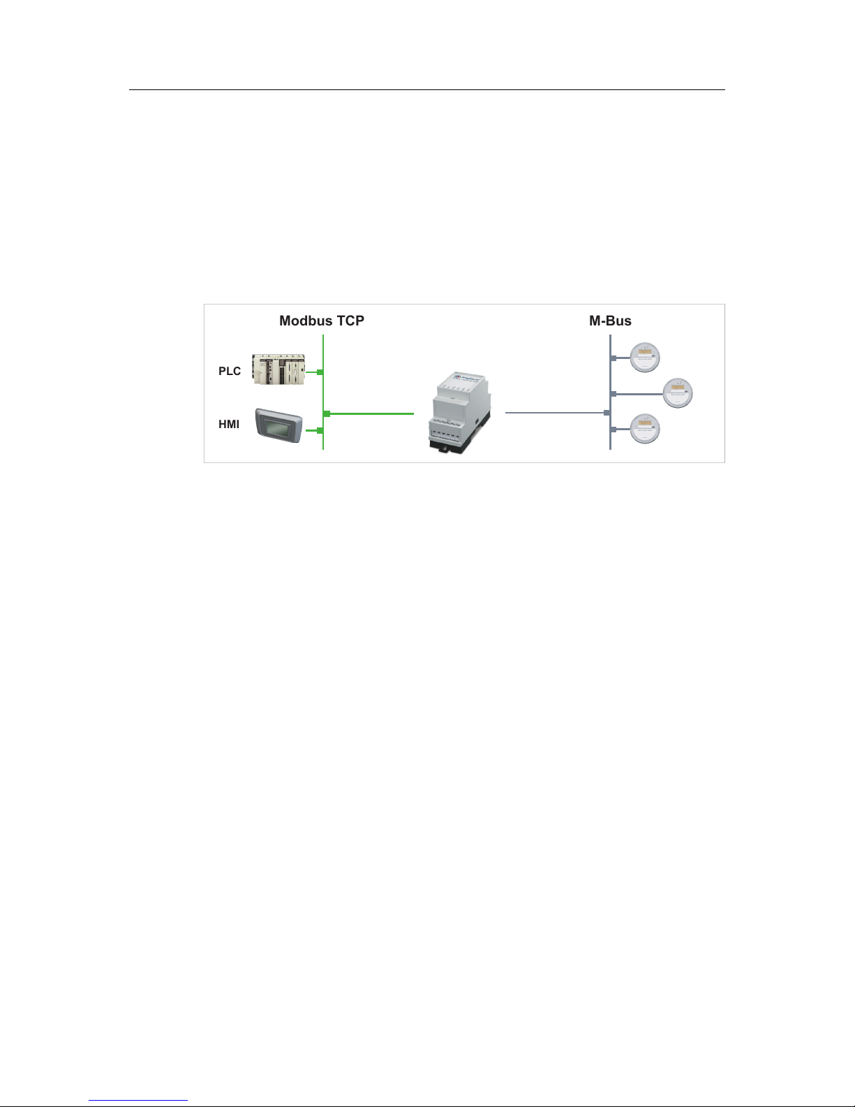
2 Product Description
The Anybus M-Bus to Modbus-TCP gateway allows measuring devices that use the M-Bus
protocol (meters) to communicate on a Modbus TCP network with up to 5 Modbus clients.
Meters can be added manually or automatically by scanning the M-Bus. The gateway
configuration maps data from each meter to a corresponding Modbus register. Meter data will
then be read automatically at an interval that can be set globally or individually for each meter.
The gateway and meters are configured through a built-in web interface, or by editing and
uploading configuration files via FTP. The complete configuration including the meter
configurations can be exported in HTML format.
PLC
HMI
Modbus TCP M-Bus
Fig. 1 Application example
Each gateway supports up to 20 or 80 unit loads (UL) on the M-Bus depending on model. 1 UL
equals 1.5 mA. Each meter can have more than one UL, so the total number of meters that can
be connected may be less than the maximum number of supported loads.
M-Bus to Modbus-TCP Gateway User Manual SCM-1202-0096-EN 2.1
Page 8
Installation 6 (46)
3 Installation
This product contains parts that can be damaged by electrostatic discharge (ESD).
Use ESD prevention measures to avoid damage.
3.1 Installation Overview
1. Mount the unit on a DIN rail.
2. Connect the M-Bus and Ethernet cables.
3. Connect the power supply and power on the unit.
4. Check the network settings and configure them as required.
5. Open the web interface to configure the unit.
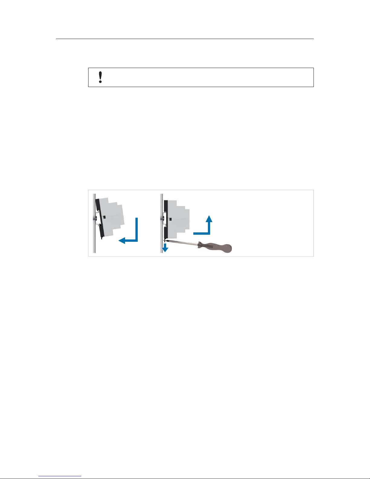
3.2 DIN Rail Mount
Fig. 2 DIN rail mounting/removing
Mounting
Hook the unit onto the rail and press it towards the rail until it snaps into place.
Removing
Pull the tab at the bottom of the unit gently downwards to release the unit.
M-Bus to Modbus-TCP Gateway User Manual SCM-1202-0096-EN 2.1
Page 9
Installation 7 (46)
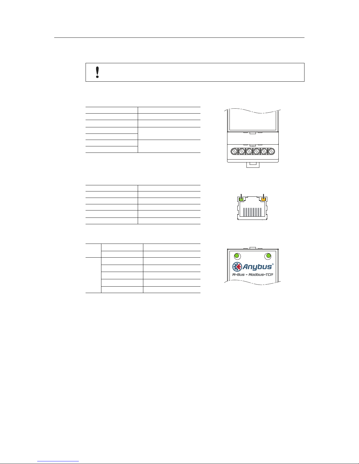
3.3 Connections and Indicators
To ensure a good M-Bus signal, make sure that power ground (GND) is NOT
electrically connected to protective earth (PE).
Maximum cross sectional area in terminal block = 2.5 mm
2
Terminal block
Pin Function
24VDC
GND
MBUS+
MBUS-
MBUS+
MBUS-
24VDC +24 VDC
GND Power ground
MBUS+
M-Bus connection
MBUSMBUS+
M-Bus connection
MBUS-
Ethernet connector (RJ45)
Pin Function
ACTIVITY LINK
18
1 TD+
2 TD3 RD+
4, 5, 7, 8 (reserved)
6 RD-
LED Indicators
ACT
OFF Inactive, standby
ACT ST
ACT ST
Green M-Bus readout
ST
Off Application not running
Green Application running
Orange Initializing
Orange, flashing M-Bus scan
Red Error
M-Bus to Modbus-TCP Gateway User Manual SCM-1202-0096-EN 2.1
Page 10
Installation 8 (46)
3.4 Network Settings
The Anybus M-Bus to Modbus-TCP gateway is normally configured using the built-in web
interface. The IP address of the gateway must be in the same subnet range of your local
network as the computer used for configuration.
Default network settings
Static IP address 192.168.1.101
Subnet mask 255.255.255.0
Default gateway 192.168.1.254
The network settings can be configured automatically from a DHCP server or manually using
the configuration tool Net discover. The settings can also be changed from the web interface
after you have logged in.
Make sure that you have all necessary information about your local network before
starting installation. Contact your network administrator if in doubt.
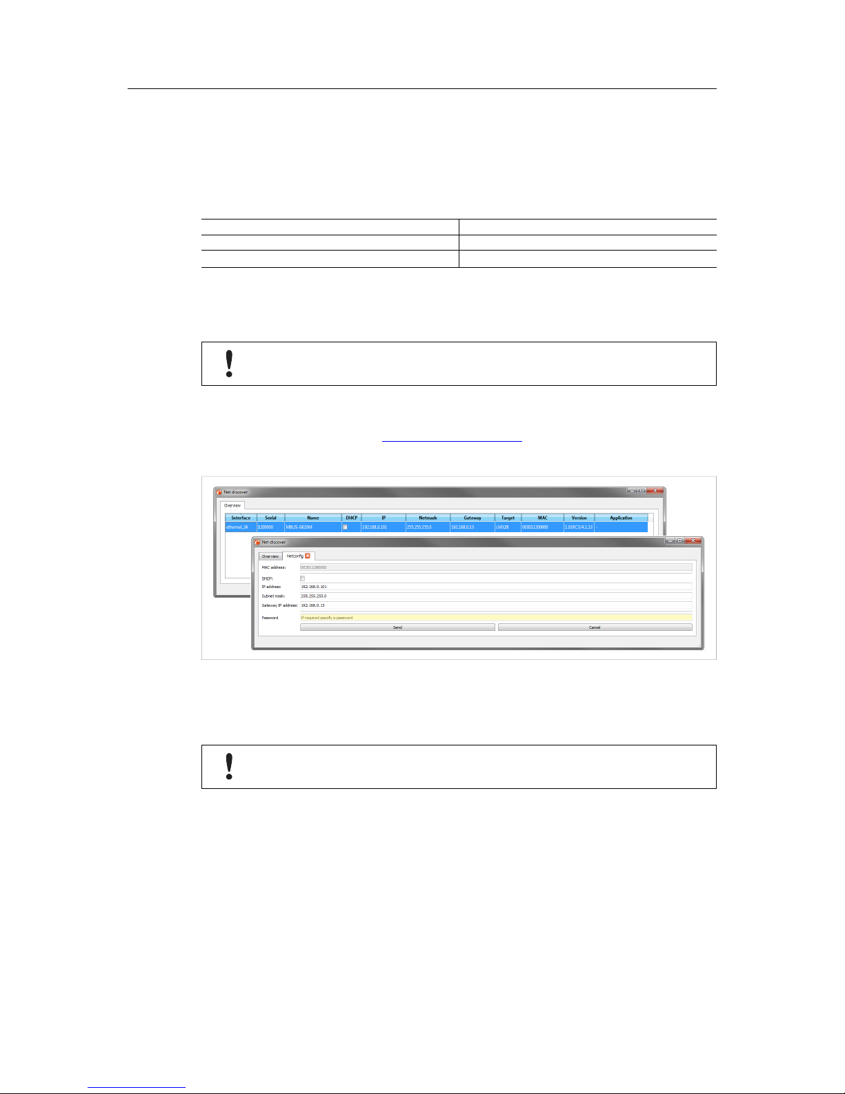
Changing Network Settings with Net discover
1. Download Net discover from www.anybus.com/support and install it on your computer.
2. In Net discover, right-click on the entry for the device and select the configuration option.
Fig. 3 Net discover
3. If the network uses static IP addressing, enter the desired IP address, subnet mask and
default gateway address. If the network uses dynamic IP addressing, check the DHCP
checkbox. Contact your network administrator if in doubt.
Do not enable DHCP if there is no active DHCP server on the network.
4. Click on Send to download the IP settings to the gateway.
Right-click on the gateway in Net discover and select HTTP Web to open the web interface in
your default browser. You can also access the web interface by entering the IP address in the
address field of any standard web browser.
Additional features of Net discover are described in Advanced Configuration, p. 37.
M-Bus to Modbus-TCP Gateway User Manual SCM-1202-0096-EN 2.1
Page 11
Configuration 9 (46)
4 Configuration
When power is applied the gateway will run the following startup sequence:
1. Applying TCP/IP network settings using DHCP or static configuration
2. Initial generation of SSL device keys (may take some time on first startup)
3. Setting system time via SNTP
4. Starting system services
5. Starting the main application
The Anybus M-Bus to Modbus-TCP gateway is normally configured using the web interface,
which gives access to all device parameters, meter configuration, and services.
The gateway can also be configured by editing and uploading configuration files directly to the
device using FTP. See Advanced Configuration, p. 37.
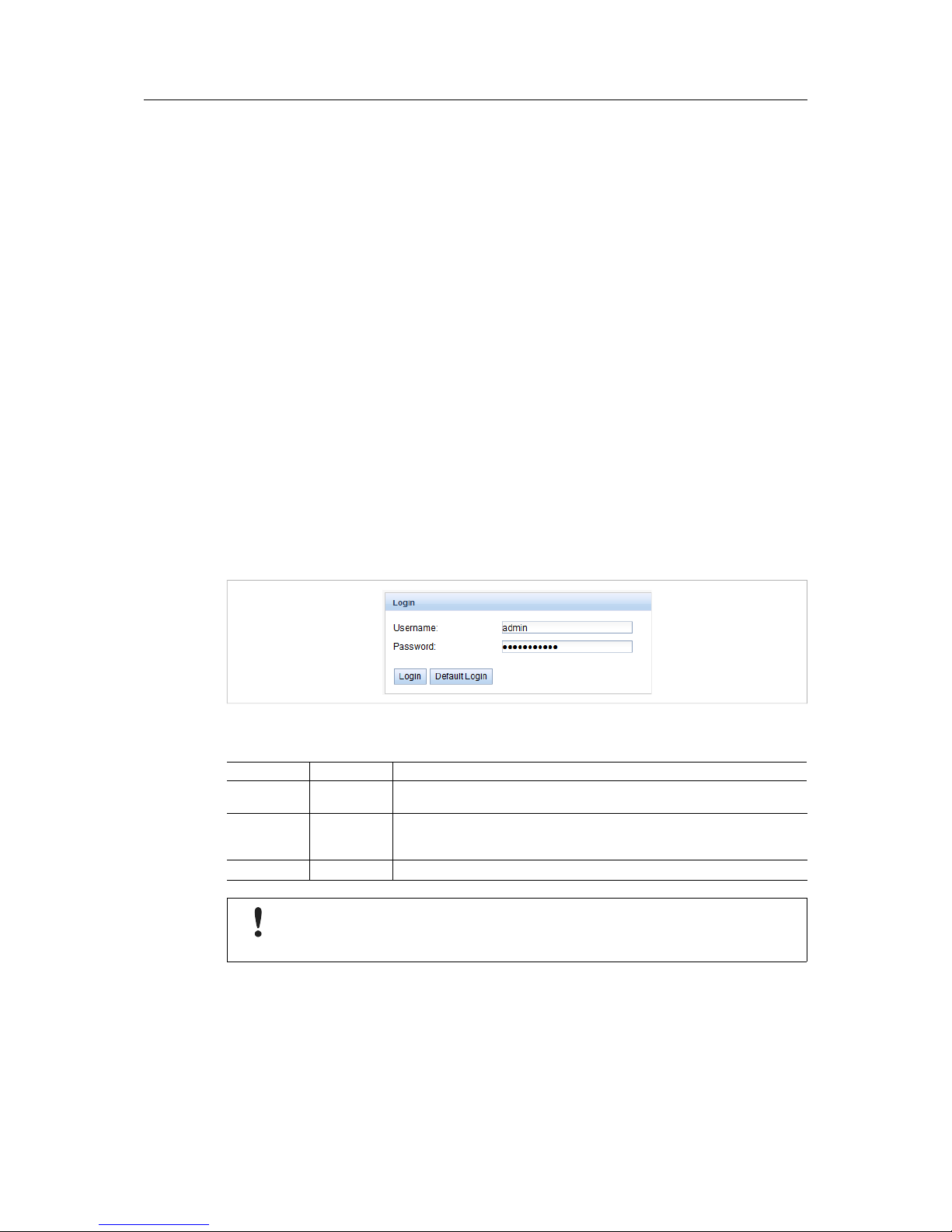
4.1 Web Interface Login
The first time you access the web interface you will be automatically logged in as the default
username (web). You can also log in as the default user manually by clicking Default Login on
the login screen. The default user only has read access.
If the default user has been disabled in the configuration, you must enter a valid username and
password and click Login.
Fig. 4 Login window
Default usernames and passwords
Username Password Description
admin admin Administrator user with root access, allows full access to all services (HTTP,
FTP, flash update, IP configuration).
web web Default user for the web interface. Allows write access to the web interface.
If a user with this name and password exists, the web server will automatically
log in with these credentials when accessed.
ftp ftp User for FTP access to the log directory of the gateway (C:/log/)
If you are logged in with write access you should always log out after finishing the
configuration, as only one user with write access can be logged in at a time. If your
session stays active, other users will not be able to log in with write access.
M-Bus to Modbus-TCP Gateway User Manual SCM-1202-0096-EN 2.1
Page 12
Configuration 10 (46)
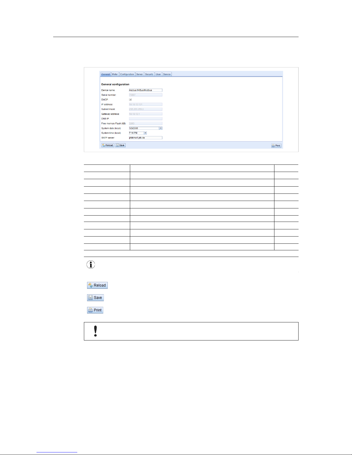
4.2 General Tab
This tab contains general network settings.
Fig. 5 General tab
Field Description Writable
Device name Name of the gateway (displayed in configuration tool) Yes
Serial number Serial number of the gateway No
DHCP Enable/disable dynamic IP addressing Yes
IP address IP address of the gateway Yes
Subnet mask Subnet mask of the gateway Yes
Gateway address IP address of the default gateway/router on the local network Yes
DNS IP IP address of the DNS server on the local network Yes
Free Memory Flash Available storage space in the internal memory No
System date (local) Current local system date Yes
System time (local) Current local system time Yes
SNTP Server IP address of SNTP time server Yes
The network parameters will be disabled if DHCP is checked.
Discard changes and reload the current settings
Save the changes and reinitialize the gateway
See Print Page, p. 21.
Changing the network configuration may restrict accessibility. Contact your
network administrator for guidance if in doubt.
If the network configuration is changed, the gateway will be available under the new IP address
after saving. All established network connections to the gateway will be terminated, and all
logged in users will be logged out.
Date and time are processed internally as UTC time (without time zone shift). The web browser
will then convert the date and time according to the local time zone of the computer.
M-Bus to Modbus-TCP Gateway User Manual SCM-1202-0096-EN 2.1
Page 13
Configuration 11 (46)
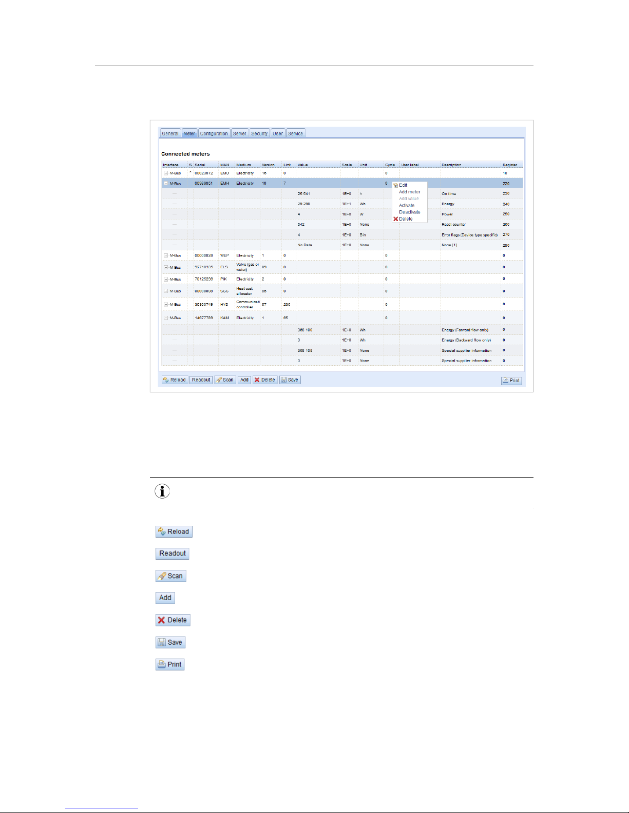
4.3 Meter Tab
This tab lists the connected meters and allows you to add and edit individual entries.
Fig. 6 Meter tab
The meter list is initially empty. After connecting meters to the gateway, click Scan to start
populating the list. The scanning settings can be changed on the Configuration tab.
Successive scans will add discovered meters to the list. Existing meters will not be deleted
even if they are unavailable. To delete a meter from the list, select it and click Delete.
Scanning can take a long time depending on the scan mode and the number of connected
meters. The scan process cannot be interrupted.
Discard the changes made on the page and reload the currently active settings.
Refresh all the read out meter values. The normal update cycle will not be not affected.
Scan for meters on the M-Bus.
Add meters not found during a scan or that do not support an automated scan.
Delete the selected meter entry. Individual value entries cannot be deleted.
Save the changes and reinitialize the gateway.
See Print Page, p. 21.
M-Bus to Modbus-TCP Gateway User Manual SCM-1202-0096-EN 2.1
Page 14

Configuration 12 (46)
The default configuration for each meter is applied immediately after scanning. Additional
changes to the configuration must be saved manually.
When activating or deactivating a meter, its meter values will automatically be enabled or
disabled according to the hierarchy. An inactive meter will be activated when one of its meter
values is enabled.
Hold down the SHIFT or CTRL keys to select multiple meters or meter values.
Meter tab fields
Field Description Writable
Interface Interface of meter (M-Bus) No
S Entry status
E = Value has been edited
* = Value display is limited in the configuration
! = Unable to read value
No
Serial Serial number of meter No
MAN Manufacturer of meter (3-letter abbreviation) No
Medium Medium of meter No
Version Version number of meter No
Link Primary address No
Value Meter reading or measurement value No
Scale Scale factor (scientific notation) No
Unit Unit No
Cycle Readout interval in seconds (0 = use general readout interval) Yes
User label User specific description of meter or value.
Included in export of CSV data, allows application specific mapping.
Yes
Description Description of meter value No
Register Modbus register address in steps of 10 Yes
The arrangement of data in the meter list corresponds to the order of the data in the M-Bus
protocol. The meaning of the values can thus be compared directly with the data sheet of the
meter. It is also possible to assign the meter values to the raw data of the meter.
Timestamps
Timestamp values transmitted within the M-Bus protocol are automatically assigned to the
other meter values where possible. This means that some of the timestamps may not appear in
the list. To enable the display of all timestamps values in the list, set the system configuration
parameter MUC_SHOWTIMESTAMPENTRIES to 1. See Configuration Files, p. 39.
Webserver capacity error
If a scan or a change in the meter list is terminated with the error message “Webserver capacity
exceeded”, see Troubleshooting, p. 31.
M-Bus to Modbus-TCP Gateway User Manual SCM-1202-0096-EN 2.1
Page 15
Configuration 13 (46)
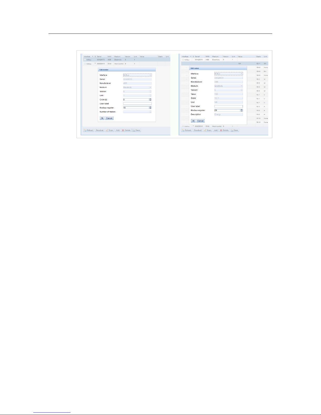
Editing Entries
Fig. 7 Editing meter and value entries
Meter and value entries can be configured by double-clicking the entry or by right-clicking the
entry and selecting Edit. The fields in the Edit dialog correlate with the fields in the meter list.
Depending on the used interface some fields may be disabled for editing.
The readout interval can be set independently for each meter in the field Cycle. If no value is
entered the global readout interval will be used, see Configuration Tab, p. 14.
Each meter or value entry can be assigned a User label for application-specific use. The label
can consist of up to 50 characters including spaces.
Valid characters in user labels:
A-Z, a-z, 0-9, ! § $ % & / ( ) = ? + , . *
Invalid characters: < > “ ”
Modbus Address Allocation
The Modbus register address can be assigned or reset for a single meter or for all meters by
right-clicking on the entry and selecting Allocate or Deallocate. If duplicate addresses are
detected an error message will be shown when the configuration is saved.
M-Bus to Modbus-TCP Gateway User Manual SCM-1202-0096-EN 2.1
Page 16

Configuration 14 (46)
4.4 Configuration Tab
This tab provides global meter settings.
Fig. 8 Configuration tab
Discard the changes made on the page and reload the currently active settings.
Save the changes and reinitialize the gateway.
See Print Page, p. 21.
M-Bus to Modbus-TCP Gateway User Manual SCM-1202-0096-EN 2.1
Page 17

Configuration 15 (46)
Configuration tab fields
Field Description Writable
Readout interval (s) Standard readout cycle of meters (in seconds). Value might be overwritten for each
meter by parameter Cycle in tab Meter
Yes
Description mode Mode of displaying the meter value description.
None No display of description
Standard Display of common value description.
Extended Extended display of value description (if not 0).
Notation: Description [Memory] <Tariff> {min|max|error}
Example: Energy [2] <1> {max}
Extended
with DIF/VIF
Extended display including DIF and VIF raw data.
Notation: Description [Memory] <Tariff> {Value Type} # XX XX XX…
Example: Energy [2] <1> # 8C 11 04
Extended
with raw data
Extended display including raw data of the complete value entry.
Notation: Description [Memory] <Tariff> {Value Type} # XX XX XX…
Example: Energy [2] <1> # 8C 11 04 96 47 06 00
DIF/VIF Display of DIF/VIF raw data
Raw data Displays the raw data of the complete meter value entry.
After changing this parameter a readout is needed to update the
meter list and to display the relevant data.
Yes
Maximum device count Maximum number of meters to scan (0 = no limitation).
Already configured meters are not affected by this parameter.
Yes
Maximum value count Maximum number of meter value entries to read during a readout (0 = no limitation).
Already configured meter value entries are not affected by this parameter.
Yes
RAW log active Activates the raw data log. Yes
M-Bus mode M-Bus scan mode (secondary, reverse secondary or primary search) Yes
Primary start address First address for primary search Yes
Primary final address Last address for primary search Yes
Secondary address
mask
Search mask for secondary search, 8 numerical characters.
F defines a wildcard. Missing characters will be filled up with leading zeros
Yes
M-Bus baud rate Baudrate for M-Bus communication (300–19200 baud) Yes
M-Bus timeout M-Bus timeout until reception of first data (ms) Yes
M-Bus idle timeout M-Bus timeout until end of reception (ms) Yes
M-Bus full timeout M-Bus timeout (complete) for reception of a whole data packet (ms) Yes
M-Bus request mode Mode of the M-Bus readout (REQ_UD2)
Standard Readout with REQ_UD2
Extended 1 Readout with Get-All-Data (DIF/VIF 7F 7E) and REQ_UD2
Extended 2 Readout with Get-All-Data (DIF 7F) and REQ_UD2
Yes
M-Bus reset mode Mode of the M-Bus Reset (before scan and readout)
None No reset
Standard Send SND_NKE to primary address of the meter or broadcast
address when using secondary adressing.
Extended 1 Send SND_NKE to primary address FD and SND_NKE to primary
address of the meter or broadcast address when using secondary
addressing.
Extended 2 Send SND_NKE and an Application Reset to primary address FD
and a SND_NKE to the primary address of the meter or to
broadcast address when using secondary addressing.
Yes
M-Bus max. multipage Limits the count of multipage requests Yes
M-Bus to Modbus-TCP Gateway User Manual SCM-1202-0096-EN 2.1
Page 18

Configuration 16 (46)
4.5 Server Tab
This tab provides settings for the Modbus TCP interface.
Fig. 9 Server tab
Server tab fields
Field Description Writable
Modbus mode Select Modbus TCP (default) or Modbus UDP.
A maximum of 5 simultaneous connections from Modbus masters are
accepted in Modbus TCP mode.
Yes
Modbus port Port number that the Modbus TCP client (master) should connect to.
Default = 502.
Yes
Modbus test Activates a dummy process image for testing purposes.
See Modbus TCP Specification, p. 22.
Yes
Modbus swap Swap the byte order from MSB first (default) to LSB first. Yes
Modbus float only Use a compressed register layout with double words per value and only
the floating point representation of a meter value.
Yes
Modbus multi slave Represent each meter as an individual Modbus slave address. Yes
Discard the changes made on the page and reload the currently active settings.
Save the changes and reinitialize the gateway.
See Print Page, p. 21.
M-Bus to Modbus-TCP Gateway User Manual SCM-1202-0096-EN 2.1
Page 19

Configuration 17 (46)
4.6 Security Tab
This tab allows you to enable/disable access to the gateway over FTP, SSH and Telnet
connections.
Fig. 10 Security tab
Server tab fields
Field Description Writable
FTP server active Enable FTP server Yes
SSH server active Enable SSH server Yes
Telnet server active Enable Telnet server Yes
Discard the changes made on the page and reload the currently active settings.
Save the changes and reinitialize the gateway.
See Print Page, p. 21.
M-Bus to Modbus-TCP Gateway User Manual SCM-1202-0096-EN 2.1
Page 20

Configuration 18 (46)
4.7 User Tab
This tab allows you to create and manage users and assign them specific access rights.
Fig. 11 User tab
User tab fields
Field Description Writable
Name Username No
Overwrite password Not used Yes
Change password User is allowed to change his/her password Yes
Sessions Number of currently open session with this user account No
Maximum sessions Max. number of simultaneous sessions for this user (-1 = unlimited) Yes
Read General Read access for tab General Yes
Write General Write access for tab General Yes
Read Meter Read access for tab Meter Yes
Write Meter Write access for tab Meter Yes
Read Config Read access for tab Configuration Yes
Write Config Write access for tab Configuration Yes
Read Server Read access for tab Server Yes
Write Server Write access for tab Server Yes
Read Security Read access for tab Security Yes
Write Security Write access for tab Security Yes
Read Service Read access for tab Service Yes
Write Service Write access for tab Service Yes
Write User Read/Write access for tab User Yes
FTP User is allowed to access the FTP server (maximum 2 users) No
Discard the changes made on the page and reload the currently active settings.
Add a new user
Delete the selected user
Save the changes and reinitialize the gateway.
See Print Page, p. 21.
M-Bus to Modbus-TCP Gateway User Manual SCM-1202-0096-EN 2.1
Page 21

Configuration 19 (46)
To edit the password and the maximum sessions setting, either double-click on the user entry
or right-click on the entry and select Edit from the context menu.
Fig. 12 Edit user
Username cannot be changed once the user has been saved.
FTP Access will only allow access to the log data directory (C:\log). Only the admin user will
have full access to the file system via FTP. This means that you can grant access to logged
data from a remote client without exposing any other data or services of the gateway.
Maximum sessions -1 = allow unlimited number of sessions.
To change the password, tick the Set password checkbox, then enter the new password in the
Password field.
Default usernames and passwords
Username Password Description
admin admin Administrator user with root access, allows full access to all services
(HTTP, FTP, flash update, IP configuration).
web web Default user for the web interface. Allows write access to the web interface.
If a user with this name and password exists, the web server will automatically
log in with these credentials when accessed.
ftp ftp User for FTP access to the log directory of the gateway (C:/log/)
Admin password
The administrator password cannot be changed from this page. To change the admin password
you must log in as admin and click the Change password link at the top of the web page.
If you lose the admin password the unit must be reset to factory defaults. Contact
Anybus support for assistance.
M-Bus to Modbus-TCP Gateway User Manual SCM-1202-0096-EN 2.1
Page 22

Configuration 20 (46)
4.8 Service Tab
This tab provides read-only information about the hardware and software for support and
troubleshooting.
Fig. 13 Service tab
Refresh the information on this page.
(disabled)
Restart the gateway and reinitialize all internal processes.
See Print Page, p. 21.
M-Bus to Modbus-TCP Gateway User Manual SCM-1202-0096-EN 2.1
Page 23

Configuration 21 (46)
4.9 Print Page
Clicking Print on any tab in the web interface will export the complete configuration (not only
the active tab) as a printable HTML page in a new browser tab or window.
The Meter Configuration section will be output in a table format that can be copied and pasted
directly into a spreadsheet program.
Fig. 14 Printable export page
M-Bus to Modbus-TCP Gateway User Manual SCM-1202-0096-EN 2.1
Page 24

Modbus TCP Specification 22 (46)
5 Modbus TCP Specification
The Modbus protocol is a single master protocol. The Modbus TCP client (master) controls the
entire communication, and the connected Modbus TCP servers (slaves) are only allowed to
respond to its requests. The Anybus M-Bus to Modbus-TCP gateway is a Modbus TCP server.
Modbus TCP communication requires an established connection between the servers and the
client over a specified TCP port. If there is a network firewall between the servers and the client,
the specified TCP port must be opened in the firewall. The default port number is 502.
5.1 Function Codes
Supported Modbus Function Codes
Code Name
Description
0x01 Read Coil Not used
0x03 Read Holding Register Reading of meter data
0x05 Write Single Coil Not used
0x06 Write Single Register Not used
0x10 Write Multiple Register Not used
0x0F Force Multiple Coil Not used
0x2B Read Device Identification Reading of device data by MEI = 0x0E
Function codes marked “Not used” are replied with ILLEGAL DATA ADDRESS (0x02). Other
unsupported codes are replied with ILLEGAL FUNCTION (0x01).
If the function code 0x2B (Read Device Identification) is used with MEI=0x03, the gateway will
respond with identification data. The values 0x01 and 0x02 are supported as Device ID code,
allowing to retrieve basic and regular device identification data.
Identification Data
Code Name Data type 20 UL model 80 UL model Type
0x00 VendorName String HMS Industrial Networks AB Basic
0x01 ProductCode String 1 2 Basic
0x02 MajorMinorRevision String 001 Basic
0x03 VendorUrl String www.anybus.com Regular
0x04 ProductName String Anybus M-Bus to Modbus-TCP Gateway Regular
0x05 ModelName String Standard Regular
0x06 UserApplicationName String Anybus M-Bus to
Modbus-TCP 20
Anybus M-Bus to
Modbus-TCP 80
Regular
5.2 Data Format
The arrangement of data in the Modbus registers corresponds to the usual structure. It uses big
endian representation. For the 16 bit registers, the higher byte is sent first, then the lower byte.
Example: value: 0x1234 transmission order: 0x12, 0x34
If number and data ranges go beyond 16 bits, representation is similar. Again, the most
significant 16 bit register is sent first and is addressed with the lowest register address.
Example: value: 0x12345678 transmission order: 0x12, 0x34, 0x56, 0x78
The byte order of 32 bit and 64 bit values can be changed within the system configuration file by
setting the parameter MODBUS_SWAP, see Configuration Files, p. 39.
M-Bus to Modbus-TCP Gateway User Manual SCM-1202-0096-EN 2.1
Page 25

Modbus TCP Specification 23 (46)
Dummy Data
For checking the data layout on the Modbus master side the gateway can be configured to
generate dummy data. See Server Tab, p. 16.
The following data will be represented via the Modbus interface according to the register layout
described in Meter Data Format, p. 26:
Address
Value Description Decoded value
0 0x0002 Serial number of device, upper word 0x2993A
1 0x993A Serial number of device, lower word
2 0x0001 Version of the communication protocol 1
3 0x006F Firmware version of device 0x6F = 111: Version 1.11
4 0x519C Timestamp of device system time, upper
word
0x519CC16D = 1369227629:Wednesday,
May 22nd 2013, 15:00:29 GMT+2
5
0xC16D Timestamp of device system time, lower
word
6 0x0000 Empty field
7 0x0100 Type field of register set in upper byte 0x01: Device entry
8 0x0000 Empty field
9 0x0000 Empty field
10 0x00BC Serial No. of meter, upper word 0xBC614E = 12345678
11 0x614E Serial No. of meter, lower word
12 0x0443 3-letter manufacturer Code 0x0443: ABC
13 0x0102 Version (upper byte) and medium (lower
byte) of the meter
0x0102: Version 1, medium 2 (electricity)
14 0x519C Timestamp of the meter, upper word 0x519CC164 = 1369227620:Wednesday,
May 22nd 2013, 15:00:20 GMT+2
15 0xC164 Timestamp of the meter, lower word
16 0x0000 Empty field
17 0x0200 Type field of register set in upper byte 0x02: Meter entry
18 0x0000 Empty field
19 0x0000 Empty field
20 0x0000 Meter value (integer), highest word 0xBC614E = 12345678
Calculation:12345678 * 10^-4 =
1234.5678 Wh
21 0x0000 Meter value (integer)
22 0x00BC Meter value (integer)
23 0x614E Meter value (integer), lowest word
24 0x449A Meter value (float), upper word 0x449A522B = 1234.567800
25 0x522B Mater value (float), lower word
26 0xFFFC Scaling factor (exponent to base 10) 0xFFFC = -4: Factor = 10^-4
27 0x0005 Type field of register set in upper
byteand unit of value in lower byte
0x00: Meter value entry
0x05: Wh
28 0x519C Timestamp of meter value, upper word 0x519CBBB3 = 1369226163:Wednesday,
May 22nd 2013, 14:36:03 GMT+2
29 0xBBB3 Timestamp of meter value, lower word
M-Bus to Modbus-TCP Gateway User Manual SCM-1202-0096-EN 2.1
Page 26

Acquiring and Processing Meter Data 24 (46)
6 Acquiring and Processing Meter Data
The main task of the Anybus M-Bus to Modbus-TCP gateway is the processing and
transmission of meter data. For proper operation, the following issues must be considered:
The following requirements must be fulfilled for the Anybus M-Bus to Modbus-TCP gateway to
process and transmit meter data:
• Each meter and value must be correctly configured and have a valid register address.
• The read out meter data must be transmittable over Modbus TCP.
• The Modbus TCP client must be able to interpret the meter data format.
6.1 Meter Configuration
Adding Meters Automatically
The Anybus M-Bus to Modbus-TCP gateway can scan the M-Bus for meters and add them
automatically without additional configuration.
Primary and Secondary Addressing
The M-Bus interface can use primary or secondary addressing when accessing a meter.
Secondary addressing is recommended if the meters should be recognized and read out
without additional configuration. This is also the default setting.
If all meters are pre-configured with a unique primary address, it is recommended to use
primary addressing and to set the start and end addresses for the scan. The read-out process
will then be considerably faster than when using secondary addressing.
Another major advantage of primary addressing is that meters of the exact same type and
configuration (but different serial numbers) can be swapped without reconfiguring the gateway.
Mixed Configuration Scan
It is also possible to scan for primary addresses first and then for secondary addresses. Meters
that are detected only in the secondary scan are appended to the existing list. Meters that are
found in both scanning runs remain unchanged if already configured.
If a meter is found for the first time during the primary scan, the primary address is used for all
further requests. This applies also to secondary scan and secondary addressing.
The scan mode is selected on the Configuration tab. The scanning process itself is started
from the Meter tab. See Configuration, p. 9.
M-Bus to Modbus-TCP Gateway User Manual SCM-1202-0096-EN 2.1
Page 27

Acquiring and Processing Meter Data 25 (46)
Adding Meters Manually
Fig. 15 Adding a meter
Meters that are connected but not found during a scan can be added manually by clicking on
the Add button in the Meter tab. The configuration of the meter must be known to be able to
add it manually.
The fields in the Add meter dialog correspond to the fields in the meter list. The following
parameters can be edited:
Serial Serial number of the meter (must be 8 digits)
Link Primary (link layer) address
Cycle (s) Readout interval in seconds (0 = use general readout interval)
User label User specific description of the meter
Modbus register Modbus register address
Number of meters If creating multiple meters with the same configuration
See also Meter Tab, p. 11.
Click OK to save the configuration. The new meter(s) will now appear in the list.
M-Bus to Modbus-TCP Gateway User Manual SCM-1202-0096-EN 2.1
Page 28

Acquiring and Processing Meter Data 26 (46)
6.2 Meter Data Format
The media IDs, value types and units used in meter data are defined in the EN 13757-3
standard. Custom types and units can be defined depending on the meter interface.
Predefined Media ID values
Index Description Index Description
0 Other 25 A/D Converter
1 Oil 26 Smoke detector
2 Electricity 27 Room sensor
3 Gas 28 Gas detector
4 Heat (outlet) 29 - 31 Reserved
5
Steam 32 Breaker (electricity)
6 Warm water 33 Valve (gas or water)
7 Water 34 - 36 Reserved
8 Heat cost allocator 37 Customer unit
9 Compressed air 38 - 39 Reserved
10 Cooling (outlet) 40 Waste water
11 Cooling (inlet) 41 Waste
12 Heat (inlet) 42 Carbon dioxide
13 Combined heat / cooling 43 - 48 Reserved
14 Bus / System component 49 Communication controller
15 Unknown medium 50 Unidirectional repeater
16 - 19 Reserved 51 Bidirectional repeater
20 Calorific value 52 - 53 Reserved
21 Hot water 54 Radio converter (system side)
22 Cold water
55
Radio converter (meter side)
23 Dual register (hot/cold) water 56 - 255 Reserved
24 Pressure
M-Bus to Modbus-TCP Gateway User Manual SCM-1202-0096-EN 2.1
Page 29

Acquiring and Processing Meter Data 27 (46)
Predefined Measurement Value Types
Index Description Index Description
0 None 46 Access code developer
1 Error flags (Device type specific) 47 Password
2 Digital output 48 Error mask
3 Special supplier information 49 Baud rate
4 Credit 50 Response delay time
5 Debit 51 Retry
6 Volts 52 Remote control (device specific)
7 Ampere 53 First storagenum. for cyclic storage
8 Reserved 54 Last storagenum. for cyclic storage
9 Energy 55
Size of storage block
10 Volume 56 Storage interval
11 Mass 57
Vendor specific data
12 Operating time 58 Time point
13 On time 59 Duration since last readout
14 Power 60 Start of tariff
15 Volume flow 61 Duration of tariff
16 Volume flow ext 62 Period of tariff
17 Mass flow 63 No VIF
18 Return temperature 64 wM-Bus data container
19 Flow temperature 65 Data transmit interval
20 Temperature difference 66 Reset counter
21 External temperature 67 Cumulation counter
22 Pressure 68 Control signal
23 Timestamp 69 Day of week
24 Time 70 Week number
25 Units for H. C. A. 71 Time point of day change
26 Averaging duration 72 State of parameter activation
27 Actuality duration 73 Duration since last cumulation
28 Identification 74 Operating time battery
29 Fabrication 75 Battery change
30 Address 76 RSSI
31 Meter specific description - can be
used to specify custom value types
(text based)
77 Daylight saving
32 Digital input 78 Listening window management
33 Software version 79 Remaining battery life time
34 Access number 80 Stop counter
35 Device type 81 Vendor specific data container
36 Manufacturer 82 Reactive energy
37 Parameter set identification 83 Reactive power
38 Model / Version 84 Relative humidity
39 Hardware version 85 Phase voltage to voltage
40 Metrology (firmware) version 86 Phase voltage to current
41 Customer location 87 Frequency
42 Customer 88 Cold/Warm Temperature limit
43 Access code user 89 Cumulative count max. power
44 Access code operator 90 - 255 Reserved
45 Access code system operator
M-Bus to Modbus-TCP Gateway User Manual SCM-1202-0096-EN 2.1
Page 30

Acquiring and Processing Meter Data 28 (46)
Predefined Units
Index Unit Description
0 None None
1 Bin Binary
2 Cur Local currency units
3 V Volt
4 A Ampere
5 Wh Watt hour
6 J Joule
7
m^3 Cubic meter
8 kg Kilogram
9
s
Second
10 min Minute
11 h Hour
12 d Day
13 W Watt
14 J/h Joule per Hour
15 m^3/h Cubic meter per hour
16 m^3/min Cubic meter per minute
17 m^3/s Cubic meter per second
18 kg/h Kilogram per hour
19 Degree C Degree celsius
20 K Kelvin
21 Bar Bar
22 Dimensionless
23 - 24 Res Reserved
25 UTC UTC
26 bd Baud
27 bt Bit time
28
mon
Month
29
y
Year
30 Day of week
31 dBm dBm
32 Bin Bin
33 Bin Bin
34 kVARh Kilo voltampere reactive hour
35 kVAR Kilo voltampere reactive
36 cal Calorie
37 % Percent
38 ft^3 Cubic feet
39 Degree Degree
40 Hz Hertz
41 kBTU Kilo british thermal unit
42 mBTU/s Milli british thermal unit per second
43 US gal US gallon
44 US gal/s US gallon per second
45 US gal/min US gallon per minute
46 US gal/h US gallon per hour
47 Degree F Degree Fahrenheit
48 - 255 Res Reserved
M-Bus to Modbus-TCP Gateway User Manual SCM-1202-0096-EN 2.1
Page 31

Acquiring and Processing Meter Data 29 (46)
Modbus Register Layout
The Anybus M-Bus to Modbus-TCP gateway uses a fixed address structure of 10 Modbus registers per
meter/meter value. Addresses are enumerated starting with 0.
• Data types using more than one register are encoded with the most significant word at the lowest
address.
• The function code 0x03 (Read Holding Register) is used for reading the data.
Within the Modbus protocol, data is formatted as either integer or float. Other data types, such as BCD, are
converted to integer values before transmission.
The first 10 Modbus register, starting at address 0, are status registers of the gateway:
Address Name Length Description
0 - 1 Serial number 32 Bit Serial number of the gateway in hexadecimal format
2 Protocol version 16 Bit Protocol version for the Modbus interface (value = 1)
3 Version 16 Bit Software version of the gateway (as integer)
4 - 5 Time stamp 32 Bit Unix timestamp of last read-out
Device system time must be set correctly (manually or via SNTP)
6 Reserved Reserved
7
Type field / reserved 16 Bit Type field for register set in the upper Byte (value=1 for device entry),
lower byte is reserved
8 - 9 Reserved Reserved
Each meter is characterized by 10 Modbus registers. Their offset has to be added to the starting register
address for each meter. They are defined as follows:
Offset Name Length Description
0 - 1 Serial number 32 Bit Serial number of meter as integer value (not BCD), only decimal
numbers allowed
2 Manufacturer ID 16 Bit Encoding of manufacturer by using different blocks of Bits: Bits 10 - 14:
first character, Bits 5 - 9: second character and Bits 0 - 4: third character,
the particular values point to the three letters, counting from "A" with
value 1
3 Version / medium 16 Bit Version of meter in the upper Byte and the medium ID in the lower Byte
4 - 5 Time stamp 32 Bit Unix timestamp of last meter read-out, system time of the gateway shall
be set correctly (manually or via SNTP)
6 Reserved Reserved
7
Type field / reserved 16 Bit Type field for register set in the upper Byte (value=2 for meter entry),
lower byte is reserved
8 Flags 16 Bit Bit 0: Value 1: Meter could not be read, Value 0: Meter could be read
correctly
Bit 1: Value 1: Not all meter values are updated, Value 0: All meter
values updated
Bit 2–15: Reserved
9 Reserved Reserved
Each meter value is characterized by 10 Modbus registers. Their offset has to be added to the starting
register address for each meter value. They are defined as follows:
Offset Name Length Description
0 - 3 Meter value 64 Bit Signed integer value (not scaled)
4 - 5 Meter value 32 Bit Floating point value (scaled to unit in register 7), IEEE 754
6 Scale factor 16 Bit Signed scale factor (exponent to the power of 10)
7
Type field / unit 16 Bit Type field for register set in the upper Byte (value=0 for meter value
entry), the lower byte is the unit index (see above).
8 - 9 Time stamp 32 Bit Unix time stamp transmitted by the meter, if there are no time stamps
transmitted by the meter, this value is set to 0
M-Bus to Modbus-TCP Gateway User Manual SCM-1202-0096-EN 2.1
Page 32

Acquiring and Processing Meter Data 30 (46)
Example Configuration
In this example, the following data will be transmitted to the Modbus master:
Address Value Name Decoded value
Device entry
0
1
0x0002
0x993A
Serial number 0x0002993A
2 0x0001 Protocol version 1
3 0x006F Version Version = 0x006F = 111 = v1.11
4
5
0x519C
0xC16D
Time stamp
0x519CC16D = 1369227629 =
Wednesday, 2013-05-22, 15:00:29 GMT+2
6 0x0000 Reserved
-
7 0x0100 Type field / reserved Type = 1 = device entry
8
9
0x0000
0x0000
Reserved
-
Meter entry
10
11
0x03F8
0x3CAA
Serial number 0x03F83CAA = 66600106
12 0x32A7 Manufacturer ID 0x32A7 = 0011.0010.1010.0111
1st letter: _011.00__.____.____ = 0x0C = 12 = L
2nd letter: ____.__10.101_.____ = 0x15 = 21 = U
3rd letter: ____.____.___0.0111 = 0x07 = 7 = G
13 0x0204 Version / medium Version = 2
Medium = 4 = Heat (outlet)
14
15
0x519C
0xC16D
Time stamp
0x519CC16D = 1369227629 =
Wednesday, 2013-05-22, 15:00:29 GMT+2
16 0x0000 Reserved
-
17 0x0200 Type field / reserved Type = 2 = meter entry
18 0x0000 Flags No read error, all meter values updated
19 0x0000 Reserved
-
Meter value entry
20
21
22
23
0x0000
0x0000
0x0000
0x010B
Meter value (integer)
0x000000000000010B = 267
Resulting value: 267 * 10^3 Wh
24
25
0x4882
0x5F00
Meter value (floating
point)
0x48825F00 = 267000.000000 Wh
26 0x0003 Scale factor Factor = 10^3
27 0x0005 Type field / unit Type = 0 = meter value entry
Unit = 5 = Wh
28
29
0x519C
0xBBB3
Time stamp 0x519CBBB3 = 1369226163 =
Wednesday, 2013-05-22, 14:36:03 GMT+2
M-Bus to Modbus-TCP Gateway User Manual SCM-1202-0096-EN 2.1
Page 33

Troubleshooting 31 (46)
7 Troubleshooting
This section lists some common problems and suggestions how to solve them.
If none of the suggested actions solves the problem, please contact Anybus support.
7.1 Hardware Errors
Gateway is not responding
After powering on the gateway it does not operate. Current consumption is ~0 mA and both
Ethernet LEDs are unlit.
1. Check that the power supply is connected with the correct polarity.
Fig. 16 Power supply voltage
2. Check that the voltage between
24VDC and GND is ~24 VDC.
Current consumption exceeds 500 mA
Fig. 17 M-Bus voltage
1. Check that the voltage between
MBUS+ and MBUS- is ~36 VDC.
2. Disconnect the gateway from the M-Bus.
3. Measure the voltage over the M-Bus terminals again.
4. Check if current consumption is back to normal.
24VDC
GND
MBUS+
MBUS-
MBUS+
MBUS-
24 V
24VDC
GND
MBUS+
MBUS-
MBUS+
MBUS-
36 V
M-Bus to Modbus-TCP Gateway User Manual SCM-1202-0096-EN 2.1
Page 34

Troubleshooting 32 (46)
7.2 Network Errors
Web interface and FTP server inaccessible
1. Run Net discover and check if the gateway appears in the list.
• If the gateway is not listed, continue to No network connection.
• If the gateway is listed:
– Run a connection test (ping).
– Try to access the FTP server in the gateway.
No network connection
The gateway cannot be accessed and is not visible in Net discover.
1. Check the physical connection (cables and connectors).
• Check that the link LED on the Ethernet port of the gateway shows an amber light and that
the activity LED is flashing green. See also Connections and Indicators, p. 7.
• Check the corresponding LEDs on the remote terminal (computer, switch, etc.).
• If necessary, replace the cables and try again.
2. If the gateway is still not visible in Net discover, check that communication is not blocked by
a firewall. Contact your network administrator if in doubt.
3. If the gateway is visible in Net discover now, run a connection test (ping).
• If no ping reply is received and the gateway is connected via a local network, try using a
direct network connection to the computer instead.
The following example IP configuration can be used with a direct connection:
IP Adress Subnet mask
Computer 192.168.1.100 255.255.0.0
gateway 192.168.1.101 255.255.0.0
Do not connect any other network devices to the computer except the gateway when using a
direct connection. A crossover Ethernet cable may be required.
No write access to the web interface
The web interface is accessible but the settings cannot be changed.
1. Make sure that you are logged in as a user with write access.
2. Write access is only allowed for one of the currently logged in users. If another user with
write access is already logged in, they will have to log out before you can log in with write
access.
If you are the only logged in user that has write access:
• Check if you have another active session in a different browser or browser tab. Close all
other sessions except the one you are using.
• A previous session may not have been closed properly. Try clearing the web browser
cache (see the documentation for your browser).
3. Log in as admin and edit the access rights for the user.
M-Bus to Modbus-TCP Gateway User Manual SCM-1202-0096-EN 2.1
Page 35

Troubleshooting 33 (46)
Web session is unexpectedly terminated
If the web session is unexpectedly terminated, this may be due to a connection timeout.
The timeout limit can be increased by editing the system parameter WEBCOM_TIMEOUT.
See Configuration Files, p. 39.
A timeout may also occur if the gateway is currently busy with the collection and transmission of
meter data, which takes priority over web communication.
FTP login fails or file list is empty
1. Log in to the web interface as admin and check the FTP user password.
2. Log in to the FTP server as admin and check the communication log.
3. If login was successful (no errors in the communication log) but the files in the gateway are
not visible, try using your FTP client in FTP passive mode.
4. Check the network configuration and that the gateway is not blocked by firewall settings.
Contact your network administrator if in doubt.
M-Bus to Modbus-TCP Gateway User Manual SCM-1202-0096-EN 2.1
Page 36

Troubleshooting 34 (46)
7.3 Meter Reading Errors
No meters are detected
A scan has been completed but none of the connected meters appear in the meter list.
1. Check the cable between the gateway and the meter and replace faulty cables.
2. Check that the voltage between terminals MBUS+ and MBUS- is ~36 VDC.
3. Check that the M-Bus interface (M-Bus mode) is enabled in the Configuration tab.
4. Check that the connected meters support configured search mode (primary or secondary).
5. Try searching for meters gradually by limiting the address space (Primary start address)
or by using a search mask (Secondary address mask).
6. Try different settings of M-Bus request mode and M-Bus reset mode.
7. Try a different M-Bus baud rate (300, 2400 or 9600), or a higher MBus timeout value.
8. If possible, disconnect the meters one by one to eliminate a possible source of error.
9. Connect another M-Bus meter (if available) and repeat the communication test with this
meter in order to locate the source of error.
10. Increase the system parameter MBUS_MAXRETRY from the default value.
See Configuration Files, p. 39.
Meters that do not respond to every request will be found easier by increasing the number
of retries the gateway makes.
Some meters are not detected
A scan has been completed but some of the connected meters do not appear in the meter list.
1. Perform the scan both as a primary scan and a secondary scan, as not every meter
supports both methods.
2. Try searching for meters gradually by limiting the address space (Primary start address)
or by using a search mask (Secondary address mask).
3. If possible, disconnect the meters one by one to eliminate a possible source of error.
4. Connect another M-Bus meter (if available) and repeat the communication test with this
meter in order to locate the source of error.
5. Increase the system parameter MBUS_MAXRETRY from the default value.
See Configuration Files, p. 39.
Meters that do not respond to every request will be found easier by increasing the number
of retries the gateway makes.
M-Bus to Modbus-TCP Gateway User Manual SCM-1202-0096-EN 2.1
Page 37

Troubleshooting 35 (46)
Meters are detected but have no data
Some meters may contain a wrong declaration of the secondary address. These meters will be
visible in the meter list but not addressable for meter readouts.
The system parameter MBUS_SELECTMASK makes it possible to mask parts of the secondary
address and replace them with a wildcard character. The version field especially is a frequent
cause of this problem (MBUS_SELECTMASK=4). See Configuration Files, p. 39.
Scanning takes too long
Under certain circumstances, scanning the M-Bus may take an extremely long time (an hour or
more).
1. Try searching for meters gradually by limiting the address space (Primary start address)
or by using a search mask (Secondary address mask).
2. Decrease the system parameter MBUS_MAXRETRY from the default value.
See Configuration Files, p. 39.
Meters that do not respond to a request will then not add excessively to the total scan time.
3. Select a different scan mode, either on the Configuration tab or by setting the system
parameter MBUS_SCANMODE.
Reversed secondary scan (SECONDARYSCANREVERSE) is often particularly useful to
speed up scanning of the M-Bus.
Gateway restarts occasionally during scan
The gateway is equipped with an internal watchdog to prevent denial of service (DoS). If a scan
takes a very long time, the watchdog may reboot the gateway.
Under certain circumstances there can be lots of collisions on the M-Bus, for example if all
meters are responding at the same time. These collisions and the resulting high current draw of
the M-Bus slaves can in exceptional cases trigger a reboot of the gateway.
1. If the scan usually takes a very long time (due to a large number of connected meters or a
slow connection) it may be necessary to increase the value of the system parameter
WATCHDOG_SCAN to prevent the watchdog from rebooting the gateway unnecessarily.
See Configuration Files, p. 39.
2. Try searching for meters gradually by limiting the address space (Primary start address)
or by using a search mask (Secondary address mask).
3. If possible, try to split the bus and scan each bus segment separately.
M-Bus to Modbus-TCP Gateway User Manual SCM-1202-0096-EN 2.1
Page 38

Troubleshooting 36 (46)
Webserver capacity error message
After a scan or a change in the meter list, the gateway (even after a reboot) may show the
following error message in the meter list:
The meter list exceeds the capacity of the internal webserver
This error message is caused by an internal limitation of the webserver. The meter list will be
generated in the gateway and meter data will be logged and sent via already configured
interfaces, but configuration of the meters via the web interface is not possible.
This can be caused by a large number of configured meters and/or very long parameter lists of
single meters. To be able to display the meter list, the number of displayed meters or the
number of values per meter need to be limited.
The following parameters on the Configuration tab can be used to set the limitation:
1. Description mode set to Standard or (if not needed) set to None.
2. Maximum device count set to the default value of 20 or 80, or to a lower value.
3. Maximum value count set to the default value of 25 or to a lower value.
4. Bus request mode set to Standard (deactivates the request of partly extensive additional
data of the meter).
5. M-Bus max. multipage set to the default value of 3 or lower.
Any change of the parameter Description Mode will be valid directly after clicking Save. All
other parameters need a regeneration of the meter list. This is accomplished by deleting all
meters and saving the now empty meter list, then performing a new scan.
Trying to save a meter list that exceeds the internal limit of the webserver leads to
the deletion of the meter list.
The meter configuration may also be changed manually by editing the meter configuration file,
see Configuration Files, p. 39. The gateway needs to be restarted for the changes to take effect.
It is not possible to display the meter list in the web interface when manual editing is used.
7.4 Meter Data Transmit Error
Meter data is not transmitted via Modbus
1. Check that the parameters for Modbus communication (IP address and port) are set
correctly in the Server tab.
2. If possible, check the network communication with the remote system using a network
analyzer such as Wireshark.
M-Bus to Modbus-TCP Gateway User Manual SCM-1202-0096-EN 2.1
Page 39

Advanced Configuration 37 (46)
8 Advanced Configuration
The file system in Anybus M-Bus to Modbus-TCP gateway can be accessed directly for
advanced configuration or troubleshooting. Right-clicking on the gateway in Net discover will
open a context menu for accessing the file system in different ways.
Fig. 18 Context menu
Editing the configuration files may restrict functionality of the device and should
always be done with care.
8.1 FTP
The file system can be accessed using a standard FTP client such as FileZilla, which is bundled
with Net discover. Right-click on the device in Net discover and select FTP to open FileZilla, or
select FTP (Default) to automatically connect and log in as the default user.
Fig. 19 FTP access
M-Bus to Modbus-TCP Gateway User Manual SCM-1202-0096-EN 2.1
Page 40

Advanced Configuration 38 (46)
8.2 SSH
Secure shell access to the file system is possible using a terminal emulator such as PuTTY,
which is bundled with Net discover and accessible from the context menu.
After logging in as admin you can use shell commands to access the file system.
Fig. 20 SSH access using PuTTY
8.3 Ping
The Ping command in Net discover can be used to test the network connection.
Fig. 21 Ping command
M-Bus to Modbus-TCP Gateway User Manual SCM-1202-0096-EN 2.1
Page 41

Advanced Configuration 39 (46)
8.4 Configuration Files
The configuration files are updated when changes are made via the web interface. They can
also be edited manually and downloaded to the gateway via FTP. Manual changes to the
configuration files will take effect after the gateway has been rebooted.
Some parameters can only be changed by editing the configuration files manually.
When editing the configuration files you must use an UTF-8 capable text editor. There is no
byte order mark (BOM) in the configuration files, which means that the text editor may need to
be manually set to use UTF-8 encoding.
Editing the configuration files may restrict functionality of the device and should
always be done with care.
Fig. 22 File system
System Configuration File
The file /app/chip.ini is the main system configuration file containing general system
parameters. Parameters that are not explicitly configured in this file will be set to their default
values.
The parameters are described in System Configuration File (chip.ini), p. 40. Parameters that
are not listed in this table should not be changed.
Meter Configuration File
Meter configuration is stored in the file /app/Device_Handle.cfg. If this file does not already
exist it will be generated when the meter list is populated.
Only the entries which differ from the default values will be stored (except version).
The parameters are described in Meter Configuration File, p. 43.
M-Bus to Modbus-TCP Gateway User Manual SCM-1202-0096-EN 2.1
Page 42

Advanced Configuration 40 (46)
System Configuration File (chip.ini)
Parameter Description Valid range Default value
[IP]
ADDRESS IP address of device 0.0.0.0 - 255.255.255.255 Not set
NETMASK Subnet mask of device 0.0.0.0 - 255.255.255.255 Not set
GATEWAY IP address of device 0.0.0.0 - 255.255.255.255 Not set
DHCP Enabling DHCP look-up 0, 1 1
TCPIPMEM Memory for the webserver (kB) 60–1000 280
[DEVICE]
NAME Name of device shown in Net discover Text (max. 20 characters) Anybus M-Bus/MTCP
20 (80)
[CONFIG]
MBUS_BAUDRATE Baud rate for serial M-Bus communication 2400
MBUS_DATABITS Data bits for serial M-Bus communication 7, 8 8
MBUS_DEBUGOUT Enables output of raw data to STDOUT 0, 1 0
MBUS_ENABLE Enables the M-Bus interface 0, 1 1
MBUS_FREEZESTORAGENUM Storage number for meter data on Freeze command 0 - 4294967295 0
MBUS_FULLTIMEOUT Maximum timeout for reading a meter (ms) 0-65535 10000
MBUS_IDLETIMEOUT Idle timeout for detecting end of communication 0-65535 100
MBUS_MAXMULTIPAGE Limits number of pages for multipage request 0 - 255 10
MBUS_MAXPRIMARYADDRESS Upper limit of address range for M-Bus primary scan 0 - 250 250
MBUS_MAXRETRY Number of retries for a M-Bus or multipage request 0 - 255 3
MBUS_MINPRIMARYADDRESS Lower limit of address range for M-Bus primary scan 0 - 250 0
MBUS_PARITY M-Bus parity: 0 = no, 1 = odd, 2 = even, 3 = mark, 4 = space 0 - 4 2
MBUS_RAWLOGENABLE Enables raw data log to drive B: 0, 1 0
MBUS_REQUESTMODE Defines request sequence for readout DEFAULT,EXT,ONLY,FREEZE DEFAULT
MBUS_RESETDISABLE Disables reset command 0, 1 0
MBUS_RESETMODE Reset mode: 0 = Reset after select, 1 = Reset prior to select, 2 = No reset 0 - 2 0
MBUS_SCANMODE Scan mode for M-Bus PRIMARYSCAN,
SECONDARYSCAN,
SECONDARYSCANALLOC,
SECONDARYSCANREVERSE,
SECONDARYSCANALLOCRE-
VERSE
SECONDARYSCAN
MBUS_
SECMASKMANUFACTURER
Predefined manufacturer ID for secondary scan Exactly 4 characters, 0-9 each
or 0xFFFF
0xFFFF
M-Bus to Modbus-TCP Gateway User Manual SCM-1202-0096-EN 2.1
Page 43

Advanced Configuration 41 (46)
System Configuration File (chip.ini) (continued)
Parameter Description Valid range Default value
MBUS_SECMASKMEDIUM Predefined medium ID for secondary scan Exactly 2 characters, 0-9 each
or 0xFFFF
0xFF
MBUS_SECMASKSERIAL Mask for serial number of meters for secondary scan Exactly 8 characters, 0-9 or 0xF
each
0xFFFFFFFF
MBUS_SECMASKVERSION Predefined version number for secondary scan Exactly 2 characters, 0-9 each
or 0xFFFF
0xFF
MBUS_SELECTMASK Disables parts of secondary address for exact selection, wildcards are used instead
(set via bit mask):
+1 = Serial number, +2 = Manufacturer, +4 = Version, +8 = Medium
0 - 15, 0
MBUS_STOPBITS Stop bits for serial M-Bus communication 1, 2 1
MBUS_TIMEOUT Timeout for M-Bus (ms) 0 - 65535 2000
MBUS_WAKEUPENABLE Enables specific wake-up request 0, 1 0
METER_MAXALLVALUECOUNT Limits the total number of meter values (0 = no limit) 0 - 65535 0
METER_MAXDEVICECOUNT Limits the number of meters (0 = no limit) 0 - 65535 0
METER_MAXVALUECOUNT Limits the number of meter values per meter (0 = no limit) 0 - 65535 0
METER_STAT_CONFIG Path for meter configuration file Text (max. 40 characters) /app/Device_Handle.
cfg
METER_TIME Interval for meter read-out (seconds)
IMPORTANT: Short cycle times and/or many meters may cause very high amounts
of data being generated.
10 - 4294967295 900
MODBUS_ADDRESS Modbus primary address or unit identifier 0 - 255 0
MODBUS_CONNECTIONTIMEOUT Connection timeout (seconds) 0 - 65535 60
MODBUS_DEBUGOUT Enables the debug output of Modbus data 0, 1 0
MODBUS_DISCONNECTTIMEOUT Timout for disconnection of an idle connection (seconds) 1 - 1000 60
MODBUS_ENABLE Enables the Modbus slaves 0, 1 0
MODBUS_MAXCONNECTIONS Maximum count of simultaneous Modbus TCP connections 0 - 80 5
MODBUS_NWPORT Network port of the Modbus slave 0 - 65535 502
MODBUS_SWAP Swap byte order of Modbus data
0: MSB first
1: LSB first
0, 1 0
MODBUSMETER_
PROTOCOLVERSION
Protocol version of the Modbus meter data:
Bit 0 = 2 registers per value (float-only)
Bit 1 = Multislave
Bit 2 = Word-Swapping of 32-bit values
Bit 3 = Dummy-mode
0 - 16 0
MUC_CONFIG_VER Version of the configuration file 1, 2 2 (explicit)
M-Bus to Modbus-TCP Gateway User Manual SCM-1202-0096-EN 2.1
Page 44

Advanced Configuration 42 (46)
System Configuration File (chip.ini) (continued)
Parameter Description Valid range Default value
MUC_LOG Sets the level for output of system data to STDOUT DEFAULT,NONE,ERRORON-
LY,ALL
DEFAULT
MUC_METERDESCRIPTION_
ENABLEFLAGS
Enable flags that control the display of the descripton field in the meter view:
Bit 0 = Description
Bit 1 = Storage-number, tariff, value type
Bit 2 = DIF/VIF raw data
Bit 3 = Complete raw data of meter value entry
0-16 1
MUC_SETDEVICES Activates writing of meter values S0,ALL,NONE S0
MUC_PROTOCOL_VER Protocol version for CSVand XML data 0, 1, 2, 3 30
MUC_SHOWTIMESTAMPENTRIES Explicit display of the meter timestamp 0, 1 0
MUC_USE_FREEZE Enables using the Freeze command prior to meter read-out 0, 1 0
SNTP_ENABLE Enables obtaining system time via SNTP 0, 1 1
SNTP_MAXTIMEOUT Maximum timeout for time request from a SNTP server (seconds) 1 - 4294967295 93600
SNTP_MINTIMEOUT Minimum timeout for a time request from a SNTP server (seconds) 1 - 4294967295 79200
SNTP_REQTIMEOUT Timeout for the SNTP request (ms) 1 - 65535 30000
SNTPIP IP address of SNTP time server Text (max. 40 characters) ptbtime1.ptb.de
WATCHDOG_IDLE Timeout for watchdog during idle state (seconds) 1 - 4294967295 120
WATCHDOG_PROCESS Timeout for watchdog during busy state (seconds) 1 - 4294967295 900
WATCHDOG_READOUT Timeout for watchdog during read-out (seconds) 1 - 4294967295 4 times the read-out
cycle, at least:
WATCHDOG_
PROCESS
WATCHDOG_SCAN Timeout for watchdog during scan process (seconds) 1 - 4294967295 1800
WEBCOM_TIMEOUT Timeout for a web session, user is logged out automatically after that period (ms) 1 - 4294967295 30000
[FTP]
CERT_COUNTRY
Certificate information for SFTP connection
Text SE
CERT_STATE Text Halland
CERT_LOCATION Text Halmstad
CERT_ORGANISATION Text HMS Industrial
Networks
CERT_ORGANISATION_UNIT Text BU Anybus
CERT_COMMON_NAME Text www.hms-networks.
com
[UDPCFG]
IPCFG_PASSWORD Password for IP configuration Text admin
M-Bus to Modbus-TCP Gateway User Manual SCM-1202-0096-EN 2.1
Page 45

Advanced Configuration 43 (46)
Meter Configuration File
Parent Element name Description Default value Example
root version Version of XML specification
-
0x08
meter
Parent element for each meter
- -
meter
interface Interface to meter
-
M-Bus
serial Serial number of meter
(hexadecimal notation with leading 0x)
0xFFFFFFFF 0x30101198
manufacturer Manufacturer of meter (abbreviation) Not set SLV
version Version of meter Not set 0x01
medium Medium of meter
(see Meter Data Format, p. 26)
Not set Electricity
primaryaddress Primary address of meter
(M-Bus or S0)
0 0x03
addressmode Used mode for addressing:
0 = Secondary,1 =: Primary
0 0
readoutcycle Specific read-out interval (seconds) 0 900
maxvaluecount Limit for number of meter values 0 12
encryptionkey Encryption key for meter (AES for
wM-Bus)
Not set, 0 0x82 0xB0 0x55 0x11 0x91
0xF5 0x1D 0x66 0xEF 0xCD
0xAB 0x89 0x67 0x45 0x23
0x01
active Enables logging of meter data or
transmission via WAN interface
1 1
rssi Received Signal Strength Indicator at last
reception (wM-Bus)
0 123
register Allocated Modbus register 0 20
value Parent element for meter values
- -
value description Description of value
(see Meter Data Format, p. 26)
None Energy
unit Unit of value
(see Meter Data Format, p. 26)
None Wh
encodetype Coding of value NODATA INT32
scale Scale factor (scientific notation) 1e0 1e-3
valuetype Type of value: instantaneous, maximum,
minimum, errorstate
instantaneous instantaneous
storagenum
Storage number of value 0 2
tariff Tariff information for value 0 3
confdata Generic data, OBIS code for value (X-X:X.
X.X*X; X=0...255)
(OBIS-ID in tab Meter)
Not set 0x01 0x00 0x01 0x08 0x00
0xFF
active Enables logging of value data or
transmission via WAN interface
1 1
register Allocated Modbus register 0 30
user
User specified, max. 50 chars
(User label in tab Meter)
Not set OG-1-Re
M-Bus to Modbus-TCP Gateway User Manual SCM-1202-0096-EN 2.1
Page 46

This page intentionally left blank
Page 47

Appendix A: Technical Data 45 (46)
A Technical Data
Technical Specifications
Model name Anybus M-Bus to Modbus-TCP gateway
Order code 024380 025070
M-Bus max. number of unit loads 20 80
M-Bus baud rates 300 to 19200 Bd
M-Bus Uspace 36 V
M-Bus Umark 24 V
M-Bus max. continuous current load 140 mA
Ethernet interface 100 Base-TX, RJ45 connector
Galvanic isolation (Ethernet) 1000 V
Dimensions (W x D x H) 89 x 35 x 58 mm
Weight 80 g
Operating temperature 0 to +50 °C
Humidity range 10 to 95 % RH, non-condensing
Input voltage 24 VDC (±5 %) SELV
Current consumption 300 mA (max.)
Power consumption 2.0 W (idle) 10 W (max.)
Mechanical rating IP20
Mounting DIN rail (EN 50022)
Certifications See www.anybus.com/support
M-Bus to Modbus-TCP Gateway User Manual SCM-1202-0096-EN 2.1
Page 48

last page
© 2018 HMS Industrial Networks AB
Box 4126
300 04 Halmstad, Sweden
info@hms.se SCM-1202-0096-EN 2.1.7247 / 2018-02-01
 Loading...