

HMI HOYME TMADP-0240-3WS Installation Instructions Manual
3-Way Switch + 24 Hour Timer–Damper Control
Easy to Follow Installation Instructions for the
A Forced Air Heating System having a Fresh Air Intake Duct leading into the return plenum
is often equipped with a Power Open Damper. Usually the thermostat causes the damper
to open for fresh air during furnace firing and allows the Damper to close when the fire
stops. To open the Fresh Air Damper at times when the furnace is not firing requires the
use of a 3-way switch (SPDT). This Timer/Adaptor, however, has been designed to
override the normal operation of a fresh air damper to remain closed at certain
intervals of the day due to the reoccurrence of foul outside air.
Purchasing a 3-way switch and the necessary extras can be time consuming. By
purchasing this Ready Mounted 3-way switch with an interval timer, TMADP-0240-3WS,
you have eliminated the trouble of buying a 3-way switch, an interval timer, an
electrical enclosure, all separately plus making the necessary connections and the
problems of assembly. This adaptor comes completely assembled with simple, easy-to-
follow installation instructions which follow:
*Manual Setting: In the “Manual” position, the switch will override the
thermostat and will power the damper to remain in the open position.
*NOTE: Engaging the Timer by positioning the white pins outward overrides both the
“Automatic/Manual” settings of the 3-way switch and the thermostat to keep the fresh air
damper closed during times of foul outside air. See “Interval Timer” page 2.
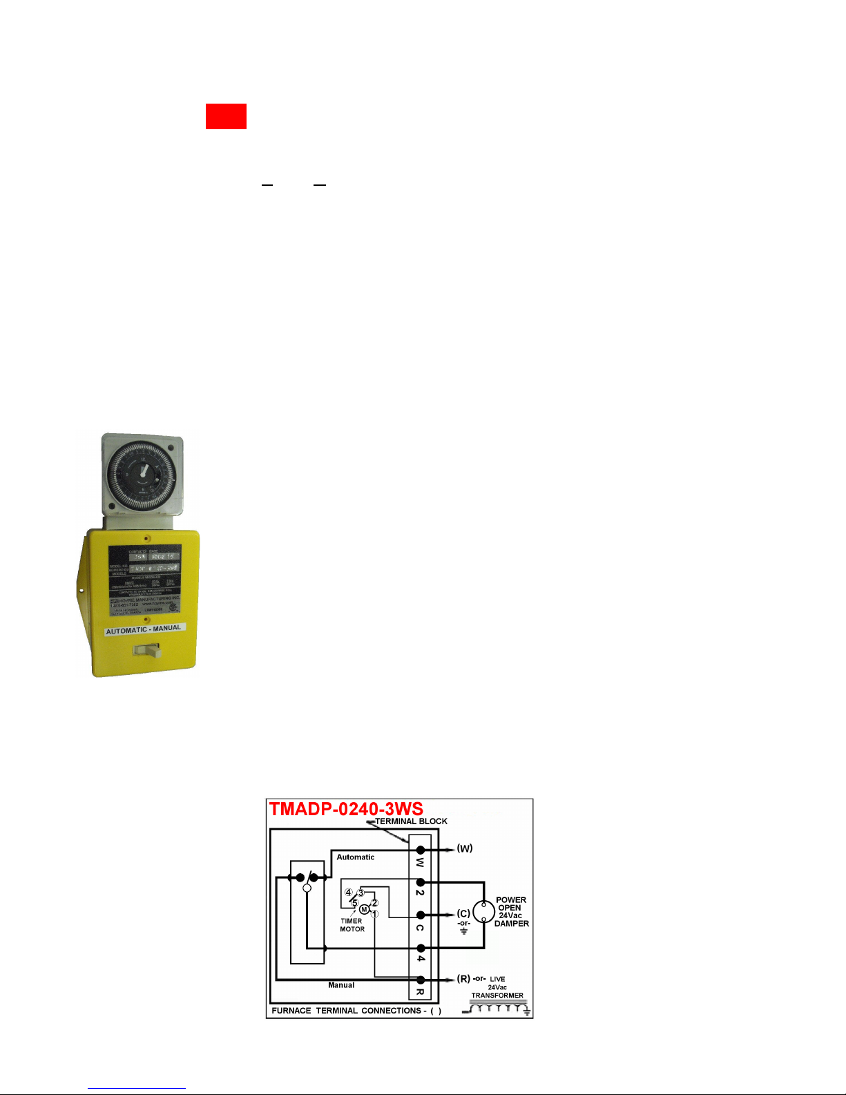
HMI HOYME Adaptor TMADP-0240-3WS
1. Mount the Adaptor TMADP-0240-3WS in a convenient place to
operate the timer on or around the furnace area with two screws
supplied.
2. Inside the adaptor are terminals “W”, “C” and “R” which are to
be connected to corresponding terminals inside your furnace. Use
3-C 18Ga. thermostat wire.
3. Connect adaptor terminals “#2” and #4 to the two wires on the
motor of the Hoyme Damper (Power Open Only).
*Automatic Setting: When the Adaptor switch is in the “Automatic”
position, the thermostat will operate normally which will cause the
damper to open during the heating cycle and will allow the damper to
close when the fire stops.
This Schematic Wiring Diagram in also on the Inside Cover of the Adaptor
1015-ld Printed in Canada
HMI HOYME Adaptor TMADP-0240-3WS
Installation Instructions
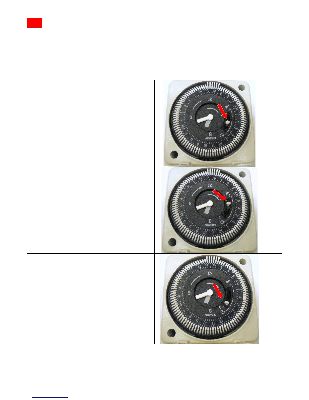
Interval Timer
In addition to the white pins which may be pulled outwards to override both the 3way switch and thermostat, there is another pin (switch) located in the centre of the
timer face as shown by the Red Arrow.
There are three positions for
the centre pin. The normal
position is in the ‘middle’. In
this position the timer will
operate as it should. Each
white pin extended outwards
on the periphery will keep the
damper closed 15 minutes.
-
Page 2
The centre pin placed in the up
‘ I ’ position will cause the
timer to act as if all the white
pins were extended. This will
override both the 3-way switch
and the thermostat. The
damper will remain continually
closed.
The centre pin in the down ‘ 0 ’
position will override the white
pins causing the timer to have
no effect on the circuit.
Therefore both the 3-way
switch and the thermostat will
have full control of the damper
to open and to close.
(For Adaptor applications, see Color Wire Diagrams #3A3; #4A3 & #8C4.)
1015-ld Printed in Canada
 Loading...