

HM-Funktechnik HM 2225, HM 2226, HM 2235, HM 2236 Installation And Operation Instruction Manual
Page 1

1
http://www.hmradio.de/
Installation- and Operation Instruction for
the Remote Control System HM22XX
V32 0108
HM-Funktechnik GmbH, Zum Handenberg 3, 66620 Primstal
Tel. 06875 9105 0, Fax. 06875 9105 10
Before operation,
read carefully this installation and
instruction manual!
Page 2

2
This instruction describes the installation and the operation of the
following HM-Funktechnik remote control systems:
HM 2225
professional remote control system for single drum
winches on forest skidders, including:
Release, pull, controlled brake release (deadman or intermittent
function), gear switch-over of the winch (optionally),
horn and accelerator, manual and automatic alarm
HM 2226
professional remote control system for single drum
winches on forest skidders, including:
Release, pull, controlled brake release (deadman or intermittent
function), gear switch-over of the winch (optionally), horn and
accelerator, manual and automatic alarm, engine start / stop
HM 2235
professional remote control system for single and dual
drum winches on forest skidders, including:
2x release, 2x pull, 2x controlled brake release (deadman or intermittent
function), gear switch-over of the winch (optionally), horn and
accelerator, manual and automatic alarm
HM 2236
professional remote control system for single and dual
drum winches on forest skidders, including:
2x release, 2x pull, 2x controlled brake release (deadman or intermittent
function), gear switch-over of the winch (optionally), horn and
accelerator, manual and automatic alarm, engine start / stop
Page 3

3
Table of Contents
1 Installation....................................................................................4
1.1 General information ...............................................................4
1.2 Mounting of the receiver........................................................4
2 Operation......................................................................................5
2.1 General information ...............................................................5
2.2 Functionality...........................................................................6
2.2.1 Button Functionality HM2225...........................................6
2.2.2 Button Combinations HM 2225........................................6
2.2.3 Button Functionality HM2226...........................................7
2.2.4 Button Combinations HM 2226........................................7
2.2.5 Button Functionality HM2235...........................................8
2.2.6 Button Combinations HM 2235........................................8
2.2.7 Button Functionality HM2236...........................................9
2.2.8 Button Combinations HM 2236........................................9
3 Safety instructions ....................................................................10
4 The receiver unit........................................................................10
4.1 Safety functions ...................................................................10
4.1.1 Self test ............................................................................10
4.1.2 Control isolation..............................................................10
4.1.3 Manual alarm function....................................................10
4.1.4 Automatic alarm function...............................................11
4.2 Safety functions during operation......................................11
4.3 Power supply requirements ................................................11
4.4 Control output protection....................................................11
4.5 Relay functionality................................................................12
4.6 DIL switch functions ............................................................13
5 The transmitter unit...................................................................14
5.1 Charging the hand held transmitter unit............................14
5.2 Battery charging cycle.........................................................14
5.3 Low battery warning ............................................................14
5.4 Data format ...........................................................................15
5.5 Radio licence ........................................................................15
6 Trouble shooting .......................................................................15
7 Marking of individual units .......................................................16
8 Cable numbers and functions ..................................................16
9 View on the pc board of the receiver.......................................17
10 Block diagram of the receiver ................................................18
11 Connector assignment and DIL-switch settings ..................19
Page 4
4
1 Installation
1.1 General information
All remote control receivers for forestry winches are equipped with a standard 7 pin or 13 pin
plug.
In general, if the make and model of the winch was specified with the order, the
plug will be correctly configured for the customer. However we strictly
recommend that the wiring between the winch and the plug is checked, to
ensure that it is correct. On the last page of this manual you will find the
configuration of the plug for your winch, please compare this against the wiring
information in the winch user‘s manual.
Once the 7/13pin plug of the remote control receiver is connected to the
corresponding socket on your winch, the unit is ready for operation !
After charging on the LG2 battery charger the transmitter is ready for use. (See section 5.1
for charging instructions)
1.2 Mounting of the receiver
There are 4 holes in the back of the receiver box for fixing the unit to the vehicle with 4 to 5
mm diammeter screws. The holes can be accessed simply by removing the plastic strips on
the top of the receiver housing however, to fit screws into the holes, the lid of the housing
will probably need to be removed. This is done by removing the plastic strips, and then
unscrewing the screws that hold on the lid. After the lid has been removed, the receiver can
then be fixed to the skidder with suitable screws.
If possible please use rubber vibration absorbers that reduces the mechanical stress for the
complete unit (they are available at your service station). Due to the special case
construction the receiver is resistant against splash water and dust.
Please do not screw the moun
ting screws directly through the top cover
of the receiver. There will be big tensions that can cause a break! Do not
install the receiver directly at the winch without adequate protection
against mechanical and weather impact!
In case you use the system on a detachable winch, mounted on the tractor using a standard
three point attachment point, it is recommended that the receiver is also not permanently
connected to the tractor. If the receiver is permanently connected, and the winch is
detached from the tractor, without unplugging the control cable, it is very likely that the cable
will be torn out of either the plug or the receiver. If the receiver is simply lying in the tractor,
for example, it is less likely that damage will occur.
Page 5
5
2 Operation
2.1 General information
The remote control series HM22xx conforms to the highest standards of safety (Details are
available in section 4.1 of this manual). The unit performs a self test every time it is switched
on and the internal status is permantly monitored. As a safety feature, if the unit detects an
error, it turns itself off. See also the block diagram in the appendix.
LED Function
Green LED: Indicates that the unit is in its standby mode
Red LED: Indicates that the unit is in its active mode
Yellow LED: Indicates the reception of a radio signal
Standby mode
The receiver unit is switched on by pressing the momentary action push button on the front
panel. The green LED should illuminate, indicating that the unit is in the standby state (see
also section 4.2).
N.B. The illumination of the Green LED indicates the standby mode.
The remote control of the receiver is still disabled until correct operation of the handheld unit
is confirmed. This is done by pressing and releasing any button on the transmitter. If the
transmitter is determined, by the receiver, to be operating correctly, the user can then
proceed to switch the system into the active mode, as explained below. (This feature
prevents unwanted and dangerous operation of the winch due to faulty parts or sticking push
switches on the transmitter unit)
Active mode
The following combination of button pressed on the transmitter will switch the receiver unit
from the standby mode into the active mode
press and hold Gas+
press and release Stop
release Gas+
The red LED on the receiver should now illuminate, indicating that the unit is in its active
mode. This means that the remote control functions are now enabled, and the system can
now control the winch (see also section 4.2).
N.B. The illumination of the red LED indicates the active mode.
Page 6
6
2.2 Functionality
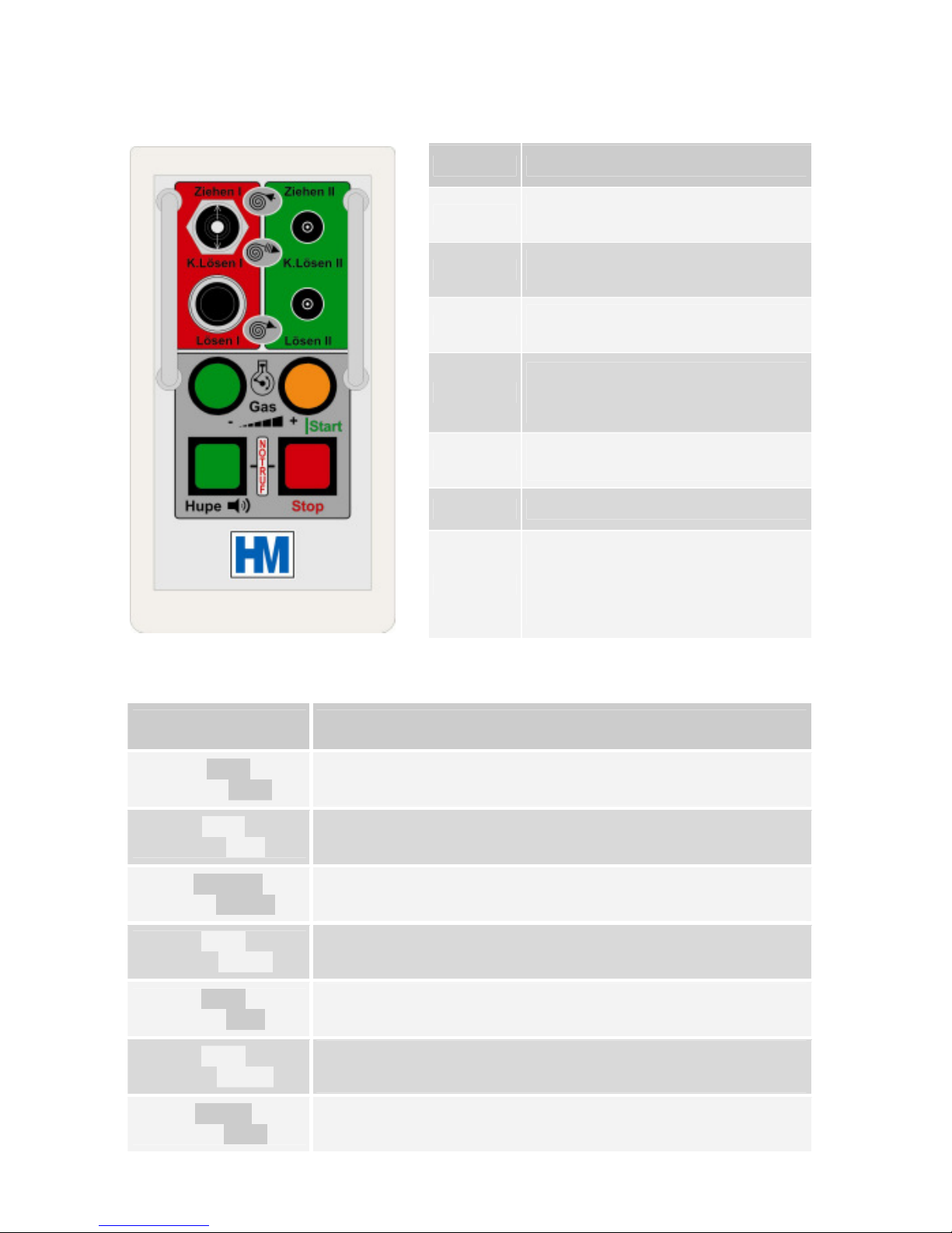
2.2.1 Button Functionality HM2225
Button Button Functionality
Ziehen I
The winch pulls in cable
(only winch 1)
K.Lösen I
Controlled brake release winch 1
(see DIL switch pos. section 4.6)
Lösen I
Brake is released
(only winch 1)
Gas+
The accelerator actuator pushes
out the compression pump lever
(see DIL switch pos. section 4.6)
Gas -
The accelerator actuator pulls in
the compression pump lever
Hupe
Sounds the vehicle horn
Stop
When the receiver is in the active
mode, switches to standby mode
(see section 4.2) Red LED will
extinguish, green LED will light.
2.2.2 Button Combinations HM 2225
Button Combination
Combination Functionality
Hold Gas+ and
press Stop
Switches the receiver unit from standby mode to active mode,
enabling the control output voltage. The red LED will illuminate
Hold Gas– and
press Stop
Switches the receiver completely off
(please use this function only if the engine is switched off)
Hold K.Lösen and
press Gas+/-
Adjusts the brake release interval of K.Lösen
(depends on DIL-Switch 6 - see section 4.6)
Hold Hupe and
press Gas+/-
Adjusts the ON/OFF-times of the brake release interval of
K.Lösen (depends on DIL-Switch 6 - see section 4.6)
Hold Hupe and
press Stop
Initiates an emergency alarm
(The external emergency call signal is triggered)
Hold Hupe and
press Ziehen
Switch-over 1./2. gear of the winch in standby mode
(release Ziehen before Hupe)
Hold Ziehen and
press Hupe
Switch-over 1./2. gear of the winch during pulling
(release Ziehen before Hupe)
Page 7

7
2.2.3 Button Functionality HM2226
Button Button Functionality
Ziehen I
The winch pulls in cable
(only winch 1)
K.Lösen I
Controlled brake release winch 1
(see DIL switch pos. section 4.6)
Lösen I
Brake is released
(only winch 1)
Gas+
The accelerator actuator pushes
out the compression pump lever
(see DIL switch pos. section 4.6)
Gas -
The accelerator actuator pulls in
the compression pump lever
Hupe
Sounds the vehicle horn
Stop
When the receiver is in the active
mode, switches to standby mode
(see section 4.2) Red LED will
extinguish, green LED will light.
2.2.4 Button Combinations HM 2226
Button Combination
Combination Functionality
Hold Gas+ and
press Stop
Switches the receiver unit from standby mode to active mode,
enabling the control output voltage. The red LED will illuminate
Hold Gas– and
press Stop
Switches the receiver completely off
(please use this function only if the engine is switched off)
Hold K.Lösen and
press Gas+/-
Adjusts the brake release interval of K.Lösen
(depends on DIL-Switch 6 - see section 4.6)
Hold Hupe and
press Gas+/-
Adjusts the ON/OFF-times of the brake release interval of
K.Lösen (depends on DIL-Switch 6 - see section 4.6)
Hold Hupe and
press Stop
Initiates an emergency alarm
(The external emergency call signal is triggered)
Hold Hupe and
press K.Lösen I
Engine Start
Hold Hupe and
press K.Lösen II
Engine Stop
Hold Hupe and
press Ziehen
Switch-over 1./2. gear of the winch in standby mode
(release Ziehen before Hupe)
Hold Ziehen and
press Hupe
Switch-over 1./2. gear of the winch during pulling
(release Ziehen before Hupe)
Page 8

8
2.2.5 Button Functionality HM2235
Button Button Functionality
Ziehen I
Ziehen II
Push lever up
winch 1 or winch 2 pulls in cable
K.Lösen I
K.Lösen II
Controlled brake release
(see DIL switch pos. section 4.6)
Lösen I
Lösen II
Pull lever down
brake 1 or brake 2 is released
Gas+
The accelerator actuator pushes
out the compression pump lever
(see DIL switch pos. section 4.6)
Gas -
The accelerator actuator pulls in
the compression pump lever
Hupe
Sounds the vehicle horn
Stop
switches to standby mode, when
the receiver is in the active mode
red LED will extinguish
green LED will light
2.2.6 Button Combinations HM 2235
Button Combination
Combination Functionality
Hold Gas+ and
press Stop
Switches the receiver unit from standby mode to active mode,
enabling the control output voltage. The red LED will illuminate
Hold Gas– and
press Stop
Switches the receiver completely off
(please use this function only if the engine is switched off)
Hold K.Lösen and
press Gas+/-
Adjusts the brake release interval of K.Lösen
(depends on DIL-Switch 6 - see section 4.6)
Hold Hupe and
press Gas+/-
Adjusts the ON/OFF-times of the brake release interval of
K.Lösen (depends on DIL-Switch 6 - see section 4.6)
Hold Hupe and
press Stop
Initiates an emergency alarm
(The external emergency call signal is triggered)
Hold Hupe and
press Ziehen
Switch-over 1./2. gear of the winch in standby mode
(release Ziehen before Hupe)
Hold Ziehen and
press Hupe
Switch-over 1./2. gear of the winch during pulling
(release Ziehen before Hupe)
Page 9

9
2.2.7 Button Functionality HM2236
Button Button Functionality
Ziehen I
Ziehen II
Push lever up, winch 1 or 2
pulls in cable
K.Lösen I
K.Lösen II
Controlled brake release
(see DIL switch pos. section 4.6)
Lösen I
Lösen II
Pull lever down, brake 1 or
brake 2 is released
Gas+
The accelerator actuator pushes out
the compression pump lever
(see DIL switch pos. section 4.6)
Gas -
The accelerator actuator pulls in the
compression pump lever
Hupe
Sounds the vehicle horn
Stop
switches to standby mode, when
the receiver is in the active mode
red LED will extinguish
green LED will light
2.2.8 Button Combinations HM 2236
Button Combination
Combination Functionality
Hold Gas+ and
press Stop
Switches the receiver unit from standby mode to active mode,
enabling the control output voltage. The red LED will illuminate
Hold Gas– and
press Stop
S
witches the receiver completely off
(please use this function only if the engine is switched off)
Hold K.Lösen and
press Gas+/-
Adjusts the brake release interval of K.Lösen
(depends on DIL-Switch 6 - see section 4.6)
Hold Hupe and
press Gas+/-
Adjusts the ON/OFF-times of the brake release interval of
K.Lösen (depends on DIL-Switch 6 - see section 4.6)
Hold Hupe and
press Stop
Initiates an emergency alarm
(The external emergency call signal is triggered)
Hold Hupe and
press K.Lösen I
Engine Start
Hold Hupe and
press K.Lösen II
Engine Stop
Hold Hupe and
press Ziehen
Switch-over 1./2. gear of the winch in standby mode
(release Ziehen before Hupe)
Hold Ziehen and
press Hupe
Switch-over 1./2. gear of the winch during pulling
(release Ziehen before Hupe)
Page 10

10
3 Safety instructions
The use of radio remote controllers lightens the load of daily work, while increasing
the daily yield.
However, in contrast to when the operator is standing next to the skidder, operating
the winches manually, the operator may be some distance away and may not be able
to appreciate the tension or strain on a winch cable, or the pull on the skidder. This
increases the chance of the system being overloaded, in which case the cable can
snap or the skidder can turn over.
It is for this reason that the operator is urged to keep a good distance from the
skidder and from loads pulled by the winches. He should keep at least half a cable
length from the whole system!
If a load becomes jammed, and the operator goes forward to work on it, the receiver
should be switched into the standby mode by pushing the Stop button on the handheld transmitter (see section 4.2).
The operation of the HM22xx radio remote control systems was designed to eliminate
the adverse of dangerous effect of interference or malfunction.
HM-Funktechnik, however, strictly recommends that if a user has any problems with a
unit it should be taken out of operation. It should then be checked by a skilled and
experienced electronic engineer, or sent to the service agent.
4 The receiver unit
4.1 Safety functions
4.1.1 Self test
The receiver has two main safety functions:The first is a continuous monitoring of the circuit
operation. If at any time the system detects a malfunction, the receiver unit will be switched
off automatically. The second safety feature is that the operator can isolate the control
output voltage from the control relays at any time. This function disables all the control
outputs, so that the remote control of equipment is disabled.
4.1.2 Control isolation
The output relay bus-bar voltage is available externally (units with a 13 pin plug only). This
allows the connection of a status indicator, for example a lamp on the back of the vehicle, to
show the operator the current status of the receiver unit. This would be a safety tool, as it
indicates to the operator whether the system is in the standby mode or in the active mode.
The receiver is programmed to test these two safety functions periodically.
4.1.3 Manual alarm function
The HM22xx systems have a manual or passive alarm operation. To activate the manual
alarm the operator must press the Stop button while holding down the Hupe button on the
transmitter. This will switch the external alarm relay and can be used to trigger an
emergency call system, such as the HM WECC2.
Page 11

11
4.1.4 Automatic alarm function
This function will only be active if the DIL switch no. 3 is set to enable it (see section 4.6).
If the receiver is on, and the operator does not press a button on the transmitter for six
minutes, the receiver switches into alarm mode and initiates a prealarm warning via the
vehicle horn. If the operator does not respond to this by pressing either the Gas+ button or a
Ziehen button, after a further two minutes, the receiver will switch into an external alarm
mode. An extern alarm trigger signal is given as an output from the receiver unit and, as
described above, it can be used to trigger an emergency call system such as the HM
WECC2.
4.2 Safety functions during operation
In case the operator has to work on a load, which is already connected to the skidder´s
winch, he is reminded to use the standby safety function. He can switch the relay bus-bar
voltage off, just by pressing the Stop button on the hand-held transmitter.
This function disables all the remote control functions so that, if the operator inadvertantly
presses a button on the transmitter, the winch is not set into operation. This control driver
voltage can be switched on again according to the procedure described in section 2.1.
4.3 Power supply requirements
The receiver unit is designed for operation on equipment with a 12 or 24VDC supply and
there are no adjustments or modifications needed. The voltage supplied to the unit from the
vehicle is switched through relays to give the control output signals, so that 12VDC is
supplied, the outputs will be at 12VDC, or if 24VDC is supplied the outputs will be at 24VDC.
4.4 Control output protection
In the receiver each output relay is protected by a 6 A poly-switch fuse installed in series
with the output relay contacts. If a maximum current of 6 A is exceeded on an output, due to
a short circuit or excessive load, the fuse will drop out and isolate that output. The fuse will
then automatically reset after the short circuit or excessive load is removed from the output.
These fuse elements are not permanently damaged by short circuits, and they protect the
rest of the circuitry from being damaged, however, they may become hot if any output is
constantly overloaded and this heat can damage the output relays.
Page 12

12
4.5 Relay functionality
Relay Relay functionality
1
For future use
2 Self test relay: O
n start up this relay is latched by pressing the button on the front
panel of the receiver unit.
If the self test routine of the microprocessor detects a malfunction at any time this
relay will be reset, completely isolating the unit from the vehicle power
supply. The
normal start up procedure can be used to restart.
3
It can be used either to drive a warning light, whenever the winches pull in cable, or to
control an hydraulic pump whenever the hydraulic system is used. The function of this
relay is controlled by DIL switch no.5 (see section 4.6 for details)
4
This relay is in series with the self test relay and switches the control relay bus
voltage. R4 can be latched on start up, after the self test funcion is complete, by
pressing the Stop button while holding the Gas+
button pressed (the normal methode
of switching into active mode)
R4 is alo used to switch between standby and active mode: The Stop
button is used
to enter Standby mode, isolating the control relays, and the same sequence as above
to enter the active mode.
The output of this relay is also available externally on the 13pin plug.
5 This relay switches if the Hupe and K. Lösen I buttons are both pressed on the hand-
held transmitter. This relay can be used to drive an engine start mechanism.
6 This relay can be used to initiate an external emergency call
. The function is
controlled by DIL switch no. 3 (see section 4.6 for details)
7 This relay switches if the Hupe and K. Lösen II buttons are both pressed on the hand-
held transmitter. This relay can be used to drive an engine stop mechanism.
8 This relay switches when the Hupe button on the hand-
held transmitter is pressed.
The output is normally open circuit and switches to the supply voltage of the vehicle
(12 or 24 VDC).
It is recommended that an external relay is installed to drive the horn
, as the horn
may draw a large current. This would cause the polyswitch fuse to drop out, and as
described above this can eventually damage the output relay.
9 This relay is controlled by the Ziehen I button on the hand-
held transmitter. It is used
to drive the clutch on winch no.1.
10
This relay drives an actuator to control the skidder´s accelerator mechanism in the
funktion Gas-. Its function is controlled by DIL switch no. 2 (see section 4.6 for details)
11 This relay is controlled by the Ziehen II button on the hand-
held transmitter. It is used
to drive the clutch on winch no.2.
12
This relay drives an actuator to control the skidder´s accelerator mechanism in the
funktion Gas+.Its function is controlled by DIL switch no. 2 (see section 4.6 for details)
13
This relay is controlled by the Lösen I button on the hand-held transmitter. It releases
the brake on winch No.1. It is controlled by DIL no. 4 (see section 4.6 for details).
14 This relay is controlled by the Lösen II button on the hand-held transmitter.It
releases
the brake on winch No.2. It is controlled by DIL no. 4 (see section 4.6 for details).
15
For future use
16
Switch-over 1./2. gear of the winch (optional)
Page 13

13
4.6 DIL switch functions
DIL-switch Functionality
1 Adjusts in combination with DIL 7 and 8 the
functionality of the release
locking function
DIL 7 DIL 8 DIL 1 = ON DIL 1 = OFF
OFF OFF Function doesn´t lock Function
is locked after
0,5 sec permanently
OFF ON Function is l
ocked after
1,0 sec for 5 Minutes
Function
is locked after
1,0 sec permanently
ON OFF Function
is locked after
2,0 sec for 5 Minutes
Function
is locked after
2,0 sec permanently
ON ON Function
is locked after
3,0 sec for 5 Minutes
Function is locked afte
r
3,0 sec permanently
The release locking function can be reset by pressing the Lösen
button
shortly (shorter than the selected locking time).
2 ON: fixed accelerator mode
If you press the Gas+ button on the hand-
held transmitter for at least
2 sec. the Gas+ function is latched.
This mode is selected if you use a
solenoid or air cylinder to set a fixed accelerator position. The function
can be reset by pressing the Gas+ button shorter than 2 seconds.
OFF: linear accelerator mode
In this mode
you can continuously adjust the engine speed with an
actuator. The adjustment is done by the Gas+ and Gas- buttons.
3 ON: Automatic alarm function enabled
Functionality described in section 4.1.4.
OFF: Automatic alarm function disabled
4 ON: Pressing the Ziehen button automatically activates the pull-
and
release-function
OFF: Pressing the Ziehen button only activates the pull-function
5 ON: R3 is activated if you either press the Ziehen or Lösen button
(Follow-up mode). You select this mode for exampl
e if you have to
drive an external hydraulic pump whenever the hydraulic system
needs pressure.
OFF: R3 is activated by pressing the Ziehen button (Movement-mode).
You select this mode for example to drive a warning light whenever
the winch is pulling.
6 ON: Pressing the K.Lösen
button activates the release function only as
long as you press the button.
OFF:
Pressing the K.Lösen
button pulses the release function in adjustable
intervals
7 - 8 See settings of DIL 1 for details
Page 14

14
5 The transmitter unit
In the hand-held remote control unit, apart from the radio transmitter module, there is an
encoder, which formats the control data for transmission, and a battery charge management
unit, which permanently monitors the state of the internal battery.
5.1 Charging the hand held transmitter unit
There is a 4.8V NiMH battery permanently installed in the transmitter. The charging cycle of
this battery is controlled by the battery charge management unit.
There are two metal belt loops on back of the transmitter unit. These loops are also the
charging contacts for the internal NiMH battery. These contacts are short circuit protected!
The battery can be charged by slotting the transmitter onto the LG2 battery charger, or any
12VDC source can be used to charge the battery by connecting it accross the two belt loops
(the polarity does not matter).
5.2 Battery charging cycle
When the transmitter is put on to charge the internal circuitry first discharges the battery
completely, to prevent damage to the battery and to maximise its working life of about 1000
charging cycles. The battery is then charged from flat. The discharging can take up to sixty
minutes, and the charging can take up to eight hours.
N.B. The complete charge needs minimum nine hours and the temperature shouldn`t be
below 0°C (32°F).
If the battery is discharged to 30% (for example) of its capacity during the day’s work, when
it is put on to charge, the internal charging circuitry will first discharge the battery completely,
then begin to charge it. This means that putting the unit on to charge for a short time when
the battery is not completely flat may, in fact, decrease the residual charge in the battery.
Important:
Charge the transmitter over-night by leaving it on the LG2 charger or
connecting it to any 12VDC voltage (polarity does not matter). If you want to use
the charging function during a working break please push together the buttons
Gas- and Gas+ after putting the transmitter on the charger. This charging is
limited to one hour.
5.3 Low battery warning
If the residual charge in the battery decreases to about 10% of its maximum capacity, while
in operation, the operator will be warned via the vehicle horn: It will sound for about 1 sec
each time any button on the transmitter is pressed (except the Stop button). This ten
percent is sufficient for a further four to five hours normal work, but this warning informs the
driver that the battery is almost flat and should soon be put on to charge.
A completely charged battery allows a couple of days of operation, depending on how much
the transmitter unit is used: The battery capacity is enough for about 18 hours continuous
transmission (pressing any button permanently).
Page 15

15
5.4 Data format
The HM22XX radio remote control systems use an highly sophisticated data protocol
between TX and RX. Apart from the control functions, a 16 bit system address and
incremental code element is transmitted, which gives the code a unique format. If the code
were transmitted continuously, it would repeat about every 30 years.
5.5 Radio licence
The HM22XX series remote controllers use HM-Funktechnik GmbH radio modules 70TXRXM1 for the data link.
The used radio modules 70TX-M1 and 70RX-M1of HM-Funktechnik GmbH are approved by
the FCC under the code PUX and also fulfil the European R&TTE directive.
6 Trouble shooting
If the remote control system doesn`t work, please check first the wiring on the skidder. Is the
plug inserted correctly? Are the contacts of the plug clean, dry and not oxidized? Is the cable
ok and without damages?
Did you charge the battery?
Does the the receiving signal lamp at the receiver lightens when you push a button on the
transmitter?
Do you hear the clicking of the relays when you push a button on the transmitter. If yes,
please check if the driver voltage is activated and the red LED lightens?
Is there maybe a short-circuit in the cable to the winch due to wrong modifications?
If nothing helps please contact our service. They will help you in either case. If it is
necessary to send in the remote control system for service please don`t forget to add a short
failure description. It is often very hard to find a failure that is not obvious or not constant.
For further information please contact our service department or your dealer. The HMFunktechnik service department is available via phone no. +49 (0)6875 9105 17
If you send units for repair to HM-Funktechnik, please send it to the following address:
HM-Funktechnik GmbH
Zum Handenberg 3
D-66620 Primstal
Please send the units with return postage payed. These expenses are refundable in case of
guarantee.
It is recommended that you inform HM-Funktechnik by phone to discuss the arrival of units
for repair. It is also helpful if you include detailed information about the problems
experienced with the unit.
Page 16

16
7 Marking of individual units
The radio remote controllers from the HM22xx series are labelled as follows:
e.g. Serial no.: 801011234/36
8 Year of production, 2005
01 Week of production
01 Counting number
1234 internal 16-bit HEX-Code
/36 Exact model of the unit, e.g. HM2236
and Frequency: 434,075 MHz
informs you about the exact channel of the unit.
This manual is valid for HM22xx radio remote controllers from serial no. 801......... !
8 Cable numbers and functions
Cable No. Funktion
1
Power supply voltage 12 - 24 VDC
2
Pull 1
3
Release 1
4
Pull 2
5
Release 2
6
Gas+
7
Gas -
8
Horn (switch high)
9
Emergency call initiation (switch high)
10
Movement or follow up relay
11
Driver voltage
12
Engine Start
13
Engine Stop
green/yellow
Earth and ground for the radio
Units with only 7-pin plug can´t use all of these functions.
Page 17

17
9 View on the pc board of the receiver
Page 18

18
10 Block diagram of the receiver
Page 19

19
Connector assignment and DIL-switch settings for winch type: ___________________________
11 Connector assignment and DIL-switch settings
Connecting lead – type of plug: ________
Contact
Function
Cable-No.
-
-
-
-
-
-
-
-
-
-
-
-
-
-
-
-
-
-
-
-
-
-
-
-
-
-
Add. connecting lead – type of plug: ____
Contact
Function
Cable-No.
-
-
-
-
-
-
-
-
-
-
-
-
-
-
Add. connecting lead – type of plug: ____
Contact
Function
Cable-No.
-
-
-
-
-
-
-
-
-
-
-
-
-
-
DIL-switch settings
on = yes off = no on off
1 Release locking mode
2 Fixed accelerator
3 Automatic alarm enabled
4 Pull releases brake autom.
5 Follow up / movement
6 K.Lösen permanent / pulsed
7 Release lock time + 1,0 sec.
8 Release lock time + 2,0 sec.
Add. connecting lead – type of plug: ____
Contact
Function
Cable-No.
-
-
-
-
-
-
-
-
Mating face view
(A) 13
-
pin plug
(B) 7 - pin plug
(C) 6 - pin Harting- plug
(D) 10 - pin Harting- plug
(E) 4-pin plug
Page 20

20
 Loading...