

Page 1
FreeSpeak II™ User Guide
(Base station version)
PN: 399G087 Rev 9 06/16/14
Page 2

Document Reference
Clear-Com FreeSpeak II User Guide
Part Number: 399G087 Revision: 9
Legal Disclaimers
Copyright © 2014 HME Clear-Com Ltd.
All rights reserved.
Clear-Com, the Clear-Com logo, Clear-Com Concert and HelixNet are registered trademarks
of HM Electronics, Inc.
The software described in this document is furnished under a license agreement and may be
used only in accordance with the terms of the agreement.
The product described in this document is distributed under licenses restricting its use,
copying, distribution, and decompilation/reverse engineering. No part of this document may be
reproduced in any form by any means without prior written authorization of Clear-Com, an
HME Company.
Clear-Com Offices are located in California, USA; Cambridge, UK; Dubai, UAE, Montreal,
Canada; and Beijing, China. Specific addresses and contact information can be found on
Clear-Com’s corporate website:
www.clearcom.com
Clear-Com Contacts
Americas and Asia-Pacific Headquarters
California, United States
Tel: +1.510.337.6600
Email: CustomerServicesUS@clearcom.com
Europe, Middle East, and Africa Headquarters
Cambridge, United Kingdom
Tel: +44 1223 815000
Email: SalesSupportEMEA@clearcom.com
Canada Office
Quebec , Canada
Tel: +1 (450) 653-9669
China Office
Beijing Representative Office
Beijing, P.R.China
Tel: +8610 65811360 / 65815577
2
FreeSpeak II User Guide
Page 3

Contents
Document Reference......................................................................................................... 2
1 Important Safety instructions ....................................................................... 9
1.1 Safety symbols .............................................................................................. 10
2 Introduction to FreeSpeak II™ ................................................................... 11
2.1 An FS II communication system .................................................................... 12
3 Installing a system ...................................................................................... 14
3.1 Placing the Base station ................................................................................ 14
3.2 Placing the antennas and splitters ................................................................. 14
3.2.1 Wiring the antennas and splitters ......................................................................... 15
3.2.2 Power supplies to the components of an FS II System ........................................ 15
3.2.3 Determining coverage areas ................................................................................ 17
3.3 Doing a site survey to determine coverage areas .......................................... 18
3.3.1 Doing a site survey with a beltpack ...................................................................... 18
3.3.2 Testing antenna handoff ....................................................................................... 20
3.3.3 Getting information on active antenna status ....................................................... 20
3.3.4 Assigning beltpacks to coverage areas ................................................................ 21
3.3.5 Conditions affecting coverage areas .................................................................... 21
3.4 Registering beltpacks .................................................................................... 21
3.4.1 Over the air (OTA) registration of a beltpack from the Base station .................... 22
4 Connecting the Base station ...................................................................... 24
4.1 Understanding the Back-Panel Connectors ................................................... 25
4.2 Connecting to partyline intercom systems ..................................................... 28
4.2.1 Clear-Com and compatible partyline .................................................................... 28
4.2.2 Connecting directly to Clear-Com partyline beltpacks ......................................... 29
4.2.3 Connecting to an RTS™ wired beltpack .............................................................. 30
4.2.4 Front-panel adjustments for partyline connections............................................... 30
4.2.5 Troubleshooting partyline connections ................................................................. 30
4.3 Wireless partyline .......................................................................................... 32
4.4 Connecting to 4-Wire and digital matrix intercom .......................................... 33
4.4.2 Connecting to Clear-Com matrix plus .................................................................. 34
4.4.3 Connecting to Clear-Com Eclipse digital matrix ................................................... 35
4.4.4 Connecting with other digital matrix intercom systems ........................................ 35
4.4.5 Connecting with other 4-wire devices ................................................................... 36
3
FreeSpeak II User Guide
Page 4

4.5 Connecting to a program audio source .......................................................... 36
4.6 IFB configuration ........................................................................................... 36
4.7 Connecting to the stage announce output ..................................................... 37
4.8 Connecting to a PC ....................................................................................... 38
4.8.1 Connecting using the serial port ........................................................................... 38
4.8.2 Connecting using the LAN port............................................................................. 39
4.9 Connecting to transceiver/antennas .............................................................. 40
4.9.1 Connecting one transceiver/antenna directly to a transceiver port ...................... 40
4.9.2 Connecting transceiver/antennas with a splitter (PD2203) .................................. 40
4.9.3 Powering an antenna or antenna splitter .............................................................. 41
5 Operating the Base station ......................................................................... 42
5.1 Introduction ................................................................................................... 42
5.2 Understanding Front-Panel Operation ........................................................... 43
5.2.1 Call Channel A ...................................................................................................... 43
5.2.2 Call Channel B ...................................................................................................... 43
6 Programming a system from the Base station .......................................... 46
6.1 Introduction ................................................................................................... 47
6.2 Using the Base station’s programming menus .............................................. 47
6.3 Saving changes ............................................................................................. 48
6.4 Changing beltpack labels .............................................................................. 48
6.4.1 To change a beltpack label ................................................................................... 48
6.5 Setting and changing port labels ................................................................... 49
6.5.1 To create a port label ............................................................................................ 50
6.6 Setting and changing group labels ................................................................ 51
6.6.1 To create a group label ......................................................................................... 51
6.7 Adding group members ................................................................................. 53
6.7.1 To assign members to a group ............................................................................. 53
6.8 Beltpacks ...................................................................................................... 54
6.9 Assigning audio routes to a beltpack ............................................................. 54
6.10 Setting the beltpack audio level ..................................................................... 56
6.11 Setting beltpack latching ............................................................................... 57
6.12 Over the Air (OTA) beltpack registration from the Base station ..................... 57
6.13 Setting input and output port levels ............................................................... 57
6.13.1 Input level ............................................................................................................. 57
4
FreeSpeak II User Guide
Page 5

6.13.2 Output level........................................................................................................... 57
6.13.3 To set the audio level for a port ............................................................................ 58
6.14 Setting port call destination ........................................................................... 59
6.15 Configuring a wired partyline ......................................................................... 61
6.15.1 To select the type of partyline system for a partyline port .................................... 61
6.15.2 To configure the Noise Gate for a partyline port .................................................. 62
6.15.3 To configure the levels for a partyline port ........................................................... 63
6.16 Base station System Menu ............................................................................ 65
6.17 System Info ................................................................................................... 66
6.18 Restoring the Defaults ................................................................................... 66
6.19 Antennas ....................................................................................................... 66
6.20 Setting the IP address ................................................................................... 67
6.21 Locking front-panel enable buttons................................................................ 67
6.22 Remote microphone kill ................................................................................. 68
6.22.1 Kill beltpack microphones ..................................................................................... 68
6.22.2 Kill partyline microphones ..................................................................................... 68
6.22.3 Kill all microphones ............................................................................................... 68
6.23 Battery indicator ............................................................................................ 68
7 Operating the wireless beltpack................................................................. 69
7.1 Overview of the wireless beltpack ................................................................. 69
7.2 Beltpack user controls ................................................................................... 70
7.2.1 Top controls .......................................................................................................... 70
7.2.2 Beltpack display .................................................................................................... 71
7.2.3 Front controls ........................................................................................................ 71
7.2.4 Beltpack bottom connectors ................................................................................. 72
7.2.5 Beltpack rear panel ............................................................................................... 73
7.3 Using the beltpack ......................................................................................... 74
7.3.1 Registering the beltpack ....................................................................................... 74
7.3.2 Charging the beltpack ........................................................................................... 74
7.3.3 Powering on the beltpack ..................................................................................... 75
7.3.4 Using the beltpack to communicate ..................................................................... 75
7.3.5 Entering and exiting Menu mode .......................................................................... 76
7.3.6 Setting and Adjusting Listen Levels ..................................................................... 76
7.3.7 Updating the beltpack software ............................................................................ 76
7.3.8 Updating the Configuration Editor ........................................................................ 76
5
FreeSpeak II User Guide
Page 6

8 Programming on the beltpack .................................................................... 77
8.1 Introduction to programming on the beltpack ................................................. 77
8.2 Configuring the beltpack volume settings ...................................................... 78
8.2.1 Configuring the beltpack channel volumes and master volume ........................... 78
8.2.2 Configuring the volume level of the line input ....................................................... 78
8.2.3 Configuring the rotary controls ............................................................................. 79
8.3 Configuring the beltpack headset .................................................................. 79
8.3.1 Setting headset autodetect ................................................................................... 79
8.3.2 Setting the sidetone level ..................................................................................... 80
8.3.3 Setting the headset limiter .................................................................................... 80
8.4 Configuring the beltpack microphone ............................................................ 80
8.4.1 Setting the microphone type ................................................................................. 80
8.4.2 Setting the microphone echo cancellation ............................................................ 81
8.5 Configuring the beltpack display and LEDs ................................................... 81
8.5.1 Setting the display and LED brightness ............................................................... 81
8.5.2 Setting the display dim timeout............................................................................. 82
8.5.3 Setting the display off timeout .............................................................................. 82
8.6 Configuring the beltpack alarm options ......................................................... 82
8.6.1 Setting the low battery alarm ................................................................................ 82
8.6.2 Setting the low battery alarm threshold ................................................................ 83
8.6.3 Setting the out of range alarm .............................................................................. 83
8.6.4 Setting the call alert .............................................................................................. 84
8.7 Selecting the beltpack role default set ........................................................... 84
8.8 Selecting the beltpack administration ............................................................ 84
8.8.1 Enabling OTA registration mode .......................................................................... 85
8.8.2 Setting full menu access ....................................................................................... 85
8.8.3 Setting system sync mode .................................................................................... 86
8.9 Setting the listen again option ....................................................................... 86
8.10 Accessing beltpack information ..................................................................... 86
8.11 Setting display mode ..................................................................................... 87
8.12 Setting system connect ................................................................................. 87
8.13 Enabling over the air (OTA) registration mode from a beltpack .................... 87
8.14 Performing a site survey ................................................................................ 88
9 Operating the transceiver/antenna ............................................................ 89
9.1 Transceiver/antenna ..................................................................................... 89
6
FreeSpeak II User Guide
Page 7

9.1.1 IP rating (International Protection Marking) .......................................................... 89
9.1.2 FS II transceiver/antenna connector panel ........................................................... 90
9.1.3 Cabling the antennas ............................................................................................ 91
9.1.4 Beltpack support capacities for transceiver/antennas .......................................... 91
9.1.5 Coverage areas under various conditions ............................................................ 91
9.1.6 Transceiver/antenna setup rules and tips ............................................................ 92
9.2 Transceiver/antenna splitter (PD2203) .......................................................... 92
9.2.1 PD2203 Front connector panel............................................................................. 93
9.2.2 PD2203 rear panel ............................................................................................... 94
9.2.3 Connecting an antenna splitter to the FS II Base station and to
transceiver/antennas ............................................................................................ 94
10
FS II Configuration Editor
........................................................................... 95
10.1 Loading configurations .................................................................................. 96
10.1.1 Loading a local configuration file .......................................................................... 96
10.1.2 Loading a configuration file from a Base station using a serial link...................... 96
10.1.3 Loading a configuration from a Base station using Ethernet ................................ 98
10.1.4 Loading a configuration file to the Base station from the Configuration
Editor .................................................................................................................... 99
10.2 Configuration Editor Screen basics ............................................................... 99
10.3 Registering beltpacks using the over the air (OTA) facility ........................... 100
10.4 Configuring beltpacks .................................................................................. 102
10.4.1 Selecting the beltpack to register or edit ............................................................ 102
10.4.2 Registering beltpacks using the micro USB cable.............................................. 103
10.4.3 Viewing beltpack registration information ........................................................... 103
10.4.4 Viewing beltpack properties ................................................................................ 104
10.4.5 Beltpack audio levels .......................................................................................... 106
10.4.6 Beltpack alarm options ....................................................................................... 107
10.4.7 Setting the beltpack role options ........................................................................ 108
10.4.8 Assig ni n g bel t pa ck keys ..................................................................................... 109
10.4.9 Configuring the Reply key .................................................................................. 110
10.4.10 Key assignment types ........................................................................................ 111
10.5 Configuring ports ......................................................................................... 111
10.5.1 Selecting the port to edit ..................................................................................... 112
10.5.2 Changing the label of the port ............................................................................ 112
10.5.3 Selecting the port type ........................................................................................ 112
10.5.4 Selecting a communication path for the port ...................................................... 113
7
FreeSpeak II User Guide
Page 8

10.5.5 Setting the input, output and VOX levels ............................................................ 115
10.6 Configuring groups and wireless partylines ................................................. 115
10.6.1 Selecting the group to edit .................................................................................. 116
10.6.2 Changing the label of the group ......................................................................... 116
10.6.3 Changing the members of the group .................................................................. 116
10.6.4 Displaying a group overview ............................................................................... 117
10.7 Reducing antenna interference ................................................................... 117
10.8 Configuring IFBs ......................................................................................... 118
10.8.1 Selecting the IFB to edit ..................................................................................... 119
10.8.2 Changing the label of the IFB ............................................................................. 119
10.8.3 Changing the IFB sources .................................................................................. 119
10.8.4 Setting the IFB dim level ..................................................................................... 119
10.9 Configuring Base station system parameters .............................................. 120
10.9.1 Editing the system parameters: .......................................................................... 120
10.9.2 Enabling Over The Air (OTA) registration .......................................................... 120
10.10 Diagnostics ................................................................................................. 120
10.10.1 Beltpack status ................................................................................................... 121
10.10.2 Static log ............................................................................................................. 123
10.10.3 Antenna status .................................................................................................... 123
10.10.4 Antenna roles...................................................................................................... 124
10.10.5 Event Log ............................................................................................................ 125
11 Specifications ............................................................................................ 127
11.1 FreeSpeak II Base station ........................................................................... 127
11.2 FreeSpeak II Beltpack ................................................................................. 128
11.3 FreeSpeak II Transceiver/Antenna .............................................................. 128
11.4 FreeSpeak II Transceiver/Antenna Splitter .................................................. 129
11.5 Transmission Method .................................................................................. 129
12 Compliance ................................................................................................ 131
8
FreeSpeak II User Guide
Page 9

1 Important Safety instructions
• Read these instructions.
• Keep these instructions.
• Heed all warnings.
• Follow all instructions.
• Do not use this apparatus near water.
• Clean only with dry cloth.
• Do not block any ventilation openings. Install in accordance with the manufacturer’s
instructions.
• Do not install near any heat sources such as radiators, heat registers, stoves, or
other apparatus (including amplifiers) that produce heat.
• Do not defeat the safety purpose of the polarized or grounding-type plug. A polarized
plug has two blades and a third grounding prong. The wide blade or the third prong is
provided for your safety. If the provided plug does not fit into your outlet, consult an
electrician for replacement of the obsolete outlet.
• Protect the power cord from being walked on or pinched particularly at plugs,
convenience receptacles, and the point where they exit from the apparatus.
• Only use attachments/accessories specified by the manufacturer.
• Use only with the cart, stand, tripod, bracket, or table specified by the manufacturer,
or sold with the apparatus. When a cart is used, use caution when moving the
cart/apparatus combination to avoid injury from tip-over.
• Unplug this apparatus during lightning storms or when unused for long periods of
time.
• Refer all servicing to qualified service personnel. Servicing is required when the
apparatus has been damaged in any way, such as power-cord supply or plug is
damaged, liquid has been spilled or objects have fallen into the apparatus, the
apparatus has been exposed to rain or moisture, does not operate normally, or has
been dropped.
• Use only chargers provided by HME/Clear-Com to charge the battery packs or
beltpacks. These include:
BAT60 Battery pack and beltpack charger manufacturered by
HME/Clear-Com
USB Charger model PA1015-050SIB200/PA1015-1SI/ PA1015-
1SI050200 provided by HME/Clear-Com with your beltpack.
• This product uses Lithium Ion Batteries which can be a fire hazard, if used
improperly. Use only HME/Clear-Com supplied BAT60 or equivalent battery packs to
ensure safe operation of the beltpack.
9
FreeSpeak II User Guide
Page 10
• When using AA Batteries follow all safety instructions from manufacturer. Do not mix
different battery chemistries. When depleted, replace all batteries.
• The in-belt pack USB charging feature has only been tested utilizing USB2.0 port.
Warning: To reduce the risk of fire or electric shock, do not expose this product to rain or
moisture.
1.1 Safety symbols
Familiarize yourself with the safety symbols in Figure 1: Safety symbols. These symbols are
displayed on the apparatus and warn you of the potential danger of electric shock if the
system is used improperly.
Figure 1-1: Safety symbols
Note: For compliance notices, see 12 Compliance.
10
FreeSpeak II User Guide
Page 11
2 Introduction to FreeSpeak II™
This chapter provides an overview of the FreeSpeak II digital wireless beltpack system.
With a Fr eeSpeak II (FS II) wireless beltpack you can roam freely around a studio or
production facility while talking and listening to all, or selected, members of the production
team. With its four communication routes, the beltpack gives you the flexibility to communicate
quickly and seamlessly with individuals or groups, and to change communication routes as
often as needed.
The system operates in the unlicensed 1.90 GHz band. With its unique and innovative digital
technology, which continually searches for unused radio frequency (RF) channels, FS II
avoids the noise and interference issues associated with traditional wireless systems using
congested UHF and VHF bands.
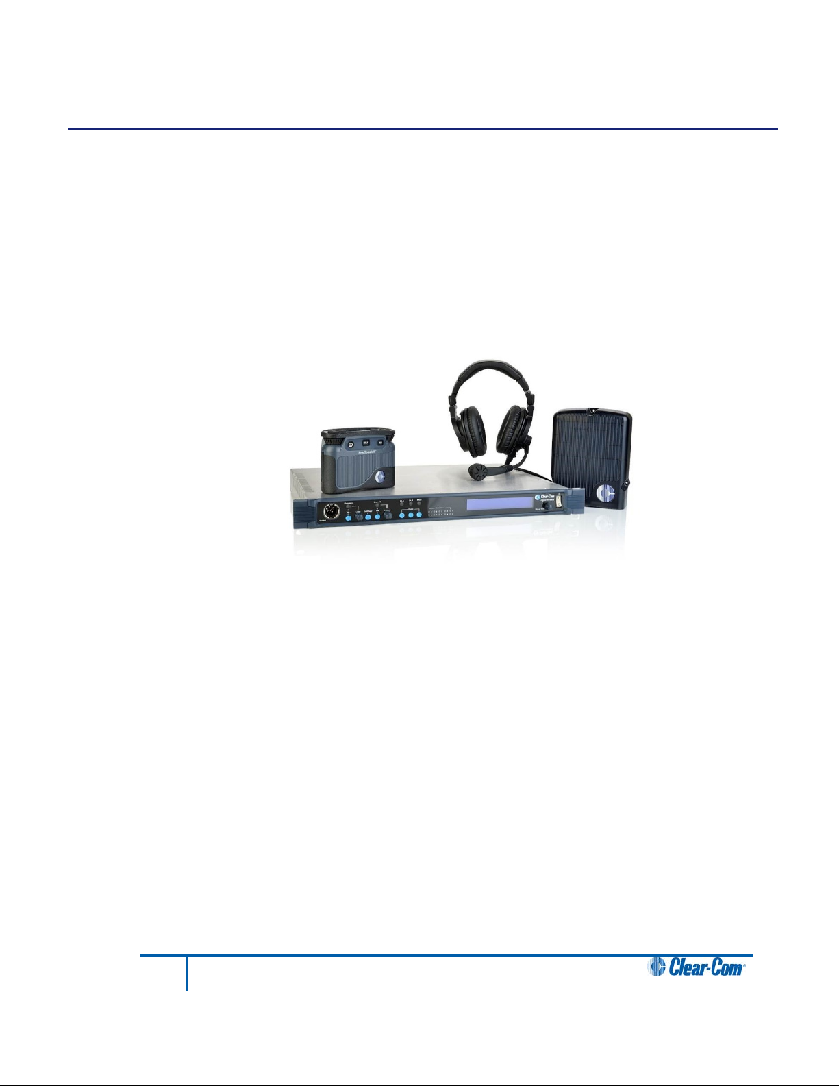
Figure 2-1 An FS II Base station, antenna, and beltpack
With FS II you can set up a wireless system specifically tailored to local needs by locating
antennas and beltpacks in areas where they are needed most. And because the beltpacks
operate in the unlicensed 1.90 GHz frequency spectrum, there is no interference with existing
wireless systems, even those located in the same production area.
You can use FS II stand-alone or connected with partyline, digital matrix intercom systems or
both. The Base station holds connections for several wired interfaces, including partylines, 4wire sources, a program audio source, and a stage announce output device. When connected
to the Base station , these devices communicate seamlessly with the wireless beltpacks.
Partyline beltpacks and 4-wire matrix stations and panels can key directly to wireless beltpack
by name.
You can configure FS II either from the Base station or from a PC Configuration Editor.
FreeSpeak II components can be used either with a Base station or with a matrix equipped
with E-Que cards in antenna or splitter mode. For more information, See the Eclipse HX
Configuration Software User Guide.
11
FreeSpeak II User Guide
Page 12
2.1 An FS II communication system
An FS II system consists of three main elements:
• The wireless beltpacks.
• The Base station that routes communication to and from wireless beltpacks and other
audio devices, and also allows you to configure the FS II system.
Note: You can also configure the system by connecting it to an Eclipse HX Matrix
and using the EHX software. For more information, see the Eclipse HX
Configuration Software User Guide.
• The antennas that provide custom coverage zones in which beltpacks can operate.
Beltpacks can roam freely between coverage zones.
FS II also includes a drop-in battery charger for the beltpack Li-Ion batteries. You can
conveniently charge the battery by placing the whole beltpack into the charger.
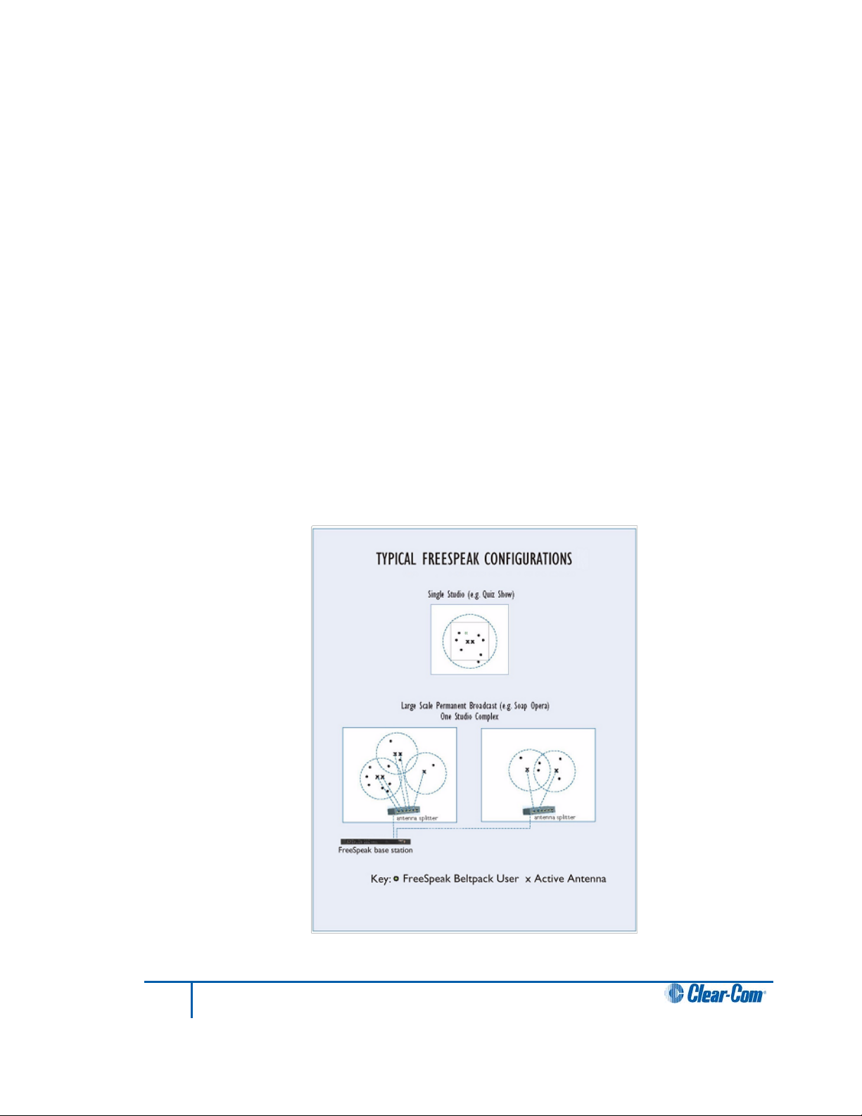
FS II operates using a cellular network of antennas located around a working environment.
The antennas connect directly to the FS II Base station with CAT-5 cable. Each antenna
provides an area or cell in which four to five full-duplex beltpacks can operate. Figure 2-2
shows an example configuration.
Beltpacks can roam among and between cells without disconnecting because each beltpack
continually signals an antenna as to the strongest available signal. When the signal from an
antenna starts to diminish due to the distance from a beltpack, the beltpack automatically
“hands off” its signal to the nearest antenna, ensuring smooth transfer.
Figure 2-2 Configurations for a studio and large-scale broadcast facility
12
FreeSpeak II User Guide
Page 13

Using an antenna splitter allows up to five antennas to be connected to one Base station
antenna port. A single FS II Base st ation supports up to twenty beltpacks and up to ten
antennas, giving a great deal of flexibility in placing beltpacks where they are needed most,
and for providing wireless reliability. Figure 2-2 illustrates how an FS II system can be set up
to operate in a single studio or in a large-scale permanent broadcast facility.
Note: Each antenna is designed to handle five beltpacks simultaneously in good conditions.
However, if int erference or propagation problems occur in an area, to ensure proper operation
and reliability, it may be more practical to install four beltpacks for each antenna.
For zones which are likely to need coverage for five or more beltpacks simultaneously you
must install a second antenna. Similarly, for good coverage for nine or more beltpacks
simultaneously, a third antenna may be required.
13
FreeSpeak II User Guide
Page 14

3 Installing a system
This chapter explains how to install a FreeSpeak II system, including cable connections,
positioning the equipment, registering beltpacks and performing a site survey to optimize
system performance. It contains the following sections:
• Placing the Base station
• Placing the antennas and splitters
• Doing a site survey to determine coverage areas
• Registering beltpacks
3.1 Placing the Base station
The first stage in setup is placing the Base station in a convenient location, knowing that it is
the central routing unit of the FS II system. It should be made accessible.
At this stage you might choose to register all of the beltpacks with the Base station, or at least
register one or two for system setup and testing.
3.2 Placing the antennas a nd splitters
The next step is to begin placing antennas and splitters to provide the necessary coverage
areas for all of the beltpacks. The first placements of antennas and splitters will be
experimental and temporary. After placing the antennas, walk through the coverage areas to
check for gaps and then re-locate the antennas accordingly.
More information on checking coverage areas is given later in this chapter, in sections:
• 3.2.3 Determining coverage areas
• 3.3 Doing a site survey to determine coverage areas
Consider the following:
• What areas will have more than five active beltpack users in them at any time? Co-
locate a second antenna there.
• Is there a central place to locate an antenna so that it will provide omnidirectional (all
directions / circular) coverage?
• Are there balcony areas, corridors, or other rooms or areas that will require coverage
with antennas?
For systems with only one or two transceiver/antennas, the cable runs will go directly from the
two transceiver ports on the Base station. If you need more than two transceiver/antennas you
will need to decide where the splitters that feed these will be located.
The Base station supports two splitters.
If you need more than one antenna splitter, the second splitter must be connected directly to
the Base station. Splitters cannot be connected in a daisy chain configuration. Each splitter
supports up to 5 antenna/transceivers which in turn support up to 5 beltpacks.
14
FreeSpeak II User Guide
Page 15

For antenna coverage options see 3.2.3 Determining coverage areas in this chapter.
3.2.1 Wiring the antennas and splitters
To wire antennas and splitters:
1) Run 4-pair shielded Ethernet cable from the Base station to the antenna or splitter,
and determine that the antenna or splitter is showing both power (green) and signal
(amber) LEDs alight when the Base station is on.
Note: To meet FCC emissions requirements, a ferrite must be fitted on any shielded Ethernet cable
plugged into either of the two ports labeled “transceivers.” The ferrite should be fitted at the
Base station end of the CAT-5 cable. Position the ferrite as close to the Base station as
possible. The manufacturer of the ferrite is Wurth Elektronix (part number is 742 711 32).
2) Run 4-pair shielded Ethernet cable from the splitter to each of the
transceiver/antennas.
3) Make sure that the local power supplies are plugged into the antennas.
If the green power LED and the amber data LED light up, then the transceiver/antenna has
sufficient power from the cable. If the amber data LED flashes, a data link is established, and
if the LED is solid, DECT synchronization is established and the system is ready to use. If
there are several longer runs and you are attempting to power the transceiver/antennas from
the Base station / splitter connection, check each one again when they are all connected. The
local powering for the transceiver/antenna is recommended in most cases to provide the most
reliable long-term FS II installation.
During the initial system setup, before walking through the system with a beltpack to check for
gaps in coverage, it is wise to avoid “permanently” installing the transceiver/antennas. Hold
them in place in some temporary way until their optimal position is determined.
Note: 4-pair shielded Ethernet cable (CAT-5/5e/6) with RJ-45 connectors on each end is specified
for connection between the Base station and the transceiver/antennas. Use of other cable can
result in markedly shorter distances of cable runs and other possibly other performance
problems.
3.2.2 Power supplies to the components of an FS II System
See figure 4-1 and figure 4-2 below for recommended powering and cable lengths for an FS II
system.
15
FreeSpeak II User Guide
Page 16
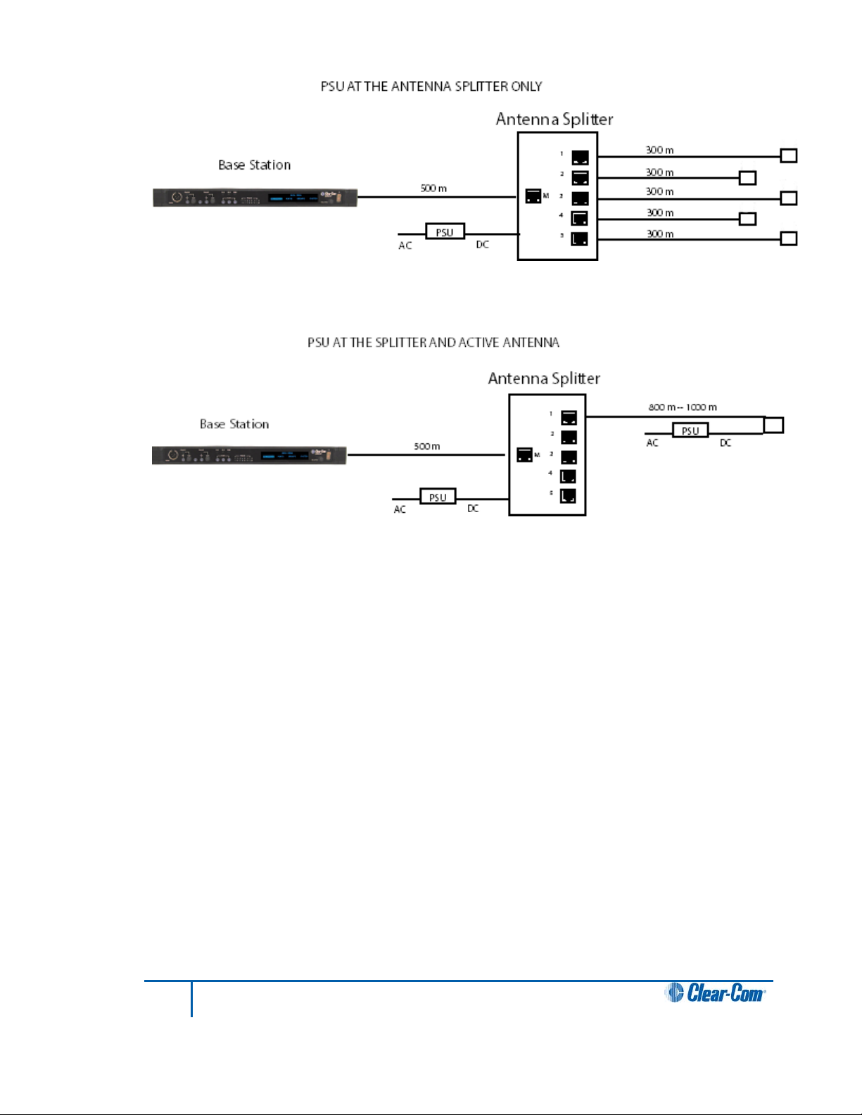
Figure 3-1 Recommended antenna and splitter powering schemes and cable lengths, psu at
splitter only
Figure 3-2 Recommended splitter and antenna powering schemes and cable lengths, psu at
splitter and antenna/transceiver
16
FreeSpeak II User Guide
Page 17
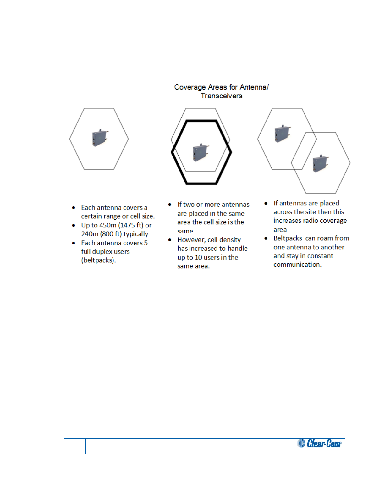
3.2.3 Determining coverage areas
After the transceiver/antennas and splitters have been initially set up proceed to test the
coverage areas and re-locate antennas and splitters, if necessary, for optimal coverage.
The following figure illustrates some FreeSpeak II coverage scenarios.
Figure 3-3 Coverage areas for FS II TAs
Note: Cells can be completely overlapped for density (by co-locating multiple antennas).
Cells can be overlapped at boundaries (increases radio coverage).
For most working systems Clear-Com uses a ratio of 3 -4 users per antenna. This is due to
system losses.
To determine coverage areas:
1) When the B ase stati on, splitter(s), and transceiver/antennas have been placed and
wired, turn on an FS II beltpack (assuming that it has been registered with the Base
station) and walk the coverage area.
Alternatively, use the “site survey” mode on the beltpack (see “Doing a Site Survey to
Determine Coverage Areas” below). It is often best to begin with one antenna in place, and
then place additional units to enhance coverage.
17
FreeSpeak II User Guide
Page 18
2) Walk through all of the areas where beltpack users will typically be moving, and note
Received signal
strength indication
(RSSI)
8-digit system name
an d 2-digit RPN
2-digit RPN
Frame error rate Link quality
any areas of weak signal, dropout, or disconnection from the system. Pay special
attention to the overlap areas between antenna coverage zones, making sure
sufficient signal strength is there from each of the transceiver/antennas to make a
clean handoff between them for the beltpack.
3) Finally, when the coverage zones have been properly and effectively set up, it is time
to program the system. See Chapter 5, “Programming a System from the Base
station” for instructions.
3.3 Doing a site survey to determine coverage areas
You might want to test coverage areas more extensively before setting up a complete system.
Testing a system in the setting in which it will be located helps to meet operational needs.
Factors in the local setting may affect the areas a system can cover, so it is important to plan
a site setup accordingly.
Doing a complete site survey, as described below, helps to set up an optimal system. You can
do a site survey using a beltpack that is connected to the system or one that is not connected
to the system.
3.3.1 Doing a site survey with a beltpa c k
1) Place the FS II Base station in a convenient location. Register one beltpack to the
Base station.
2) Place one connected antenna in the center of the coverage area.
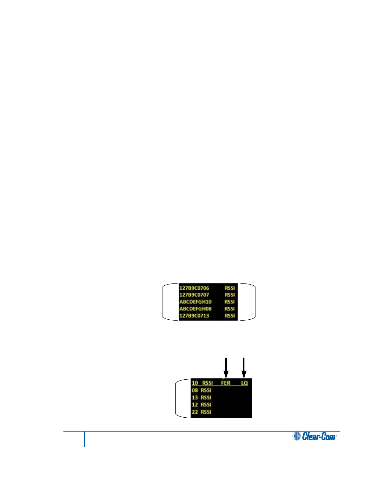
3) Put the beltpack into Site Survey mode using t he beltpack menu. See 7 Operating
the wireless beltpack. The following figures show the information that the Site
Survey mode displays for connected and unconnected beltpacks.
Figure 3-4 An unconnected beltpack site survey screen
Figure 3-4 A connected beltpack site survey screen
18
FreeSpeak II User Guide
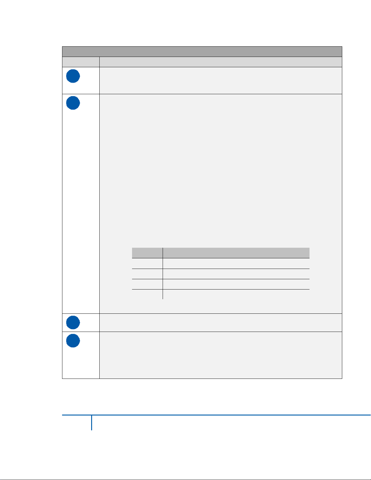
Page 19

Parameter
Meaning
Received Signal Strength Indication (RSSI)
Frame Error Rate (FER)
A measure of the signal connection quality.
Zone A
1 user
Zone C
4 users
Zone B
5 users
A measure of the signal strength in a wireless
environment. The higher the value, the
stronger the signal.
The lower the FER, the better the signal
connection.
Link Quality (LQ)
A combined quality metric ranging from 1
(poor) to 5 (high).
Table 3-1 Key to site survey terms
4) Walk around the antenna with the beltpack, monitoring the beltpack signal strength
and goodness rating at various distances.
The signal strength is shown in the Received Signal Strength Indication (RSSI) field.
• The signal strength number will fluctuate, ranging between 0 - 59 as you walk
through the coverage area, and may even fluctuate as you stand still. As a rule-ofthumb the best system performance will be obtained when the signal strength
remains at 30 or above. If the signal strength falls below 30 the beltpack may start
losing audio. This is the limit of the coverage zone.
• A high Received Signal strength indication and a high Error rate may indicate that
there is another RF system causing interference.
A beltpack can transmit to an antenna at a range of approximately 500m in good conditions.
5) Draw a map of the coverage zone for the antenna. The coverage zone is the area
where the signal strength, as a rule-of-thumb, is 30 or above and the Line Quality is
3-5.
6) Repeat this process for as many antennas as necessary to cover the required area.
Overlap coverage zones so that there is no area where the signal strength is below
30, and no area where the error rate is above a few percent.
7) The antenna placement will need to be adjusted to get the best coverage.
In some environments you might observe that despite having a high signal strength, the
beltpack consistently reports a high error rate.
19
FreeSpeak II User Guide
Figure 3-5 Mapping overlapping coverage zones
Page 20

This could be due to two things:
• In-band interference from an RF source broadcasting in the DECT area of the
spectrum. This can be verified using a DECT band monitor or by using a Spectrum
Analyzer.
• Long Delay Spread Multipath, where the signal is bounced off a number of reflective
surfaces, such as metal ceilings, gantries, walkways or other large structures. This
problem is greatest where the reflective surface is large and exists at a range of
distances from the antenna. To resolve this problem, consider siting the antenna
where it cannot “see” the reflective surface or installing a reflector close to the
antenna between it and the reflective surface.
3.3.2 Testing antenna handoff
After testing the coverage areas for individual antennas, test the handoff between the
antennas. When you walk through a coverage area with the beltpack, the beltpack searches
to find the antenna with the best signal strength, and switches transmission to that antenna.
Therefore the beltpack continually hands off transmission among antennas as you move
through the coverage area. You can determine which antenna the beltpack is connected to
using the Configuration Editor Diagnostics Tool.
To test antenna handoff, connect any additional antennas in the installation and walk through
the coverage areas to ensure that the coverage is continuous and complete, without audio
breakups. Reposition antennas if necessary.
3.3.3 Getting information on active antenna status
You can also monitor which beltpacks are connected to which antennas using the Base
station SYSTEM menu and using the Configuration Editor Diagnostics Tool.
When you select ANTNS from the SYSTEM menu, the display shows the status of the active
antennas that are connected to the Base station, and shows the slots on each antenna that
are occupied by beltpacks. This information may be useful during a site survey, or when
troubleshooting coverage areas or antenna connections.
A typical display is shown below:
Figure 3-6 ANTNS menu
The numbers 1 through 10 represent the maximum number of antennas that can be
connected to the Base station. Numbers 1 through 5 can be positions on a splitter connected
to transceiver port 1, while 6 through 10 can be positions on a splitter connected to transceiver
port 2. An antenna connected directly to transceiver port 2 would appear at position 6.
“__” indicates an empty slot on an active antenna that is connected to the Base station. A
number in place of a “__” indicates that this slot is occupied by the indicated beltpack.
20
FreeSpeak II User Guide
Page 21

Blank spaces next to an antenna number indicate that no connected antenna has been
detected in this position.
So the above display would indicate that five antennas are connected to the Base station in
positions 1, 2, 3, 6, and 7. There are no active antennas in positions 4, 5, 8, 9, and 10.
There are 4 beltpacks currently connected. Beltpacks 2 and 4 occupy the first 2 slots of
antenna 3; beltpack 1 occupies the first slot of antenna 6; and beltpack 3 occupies the first slot
of antenna 7.
The display updates every 4 seconds to reflect changes in antenna status and beltpack
connections.
Rotate or push in the setup/enter encoder to exit this menu.
3.3.4 Assigning beltpacks to coverage areas
Each antenna is designed to handle five beltpacks simultaneously. Although it can achieve
this in good conditions, this may not always be possible for a number of reasons. First,
interference or propagation problems may mean that not all antenna slots are available all the
time. Second, a beltpack constantly searches for the best antenna signal, and may frequently
switch antennas. To make this transmission seamless, a beltpack maintains the connection to
its current antenna until it is confident that the new antenna is functioning well. Therefore, for a
short period of time during this transition, a single beltpack can occupy slots on more than one
antenna.
This means that for zones likely to need coverage for five or more beltpacks simultaneously it
is recommended that a second antenna is installed. Similarly, for good coverage for nine or
more beltpacks simultaneously, a third antenna may be required.
3.3.5 Conditions affecting coverage areas
The environment in which a system is located affects the coverage area for any particular
beltpack/antenna combination. The presence of walls, floors, ceilings, trees, shrubbery,
people, and numerous other items may affect the coverage zone. Metallic objects, safety
doors, lighting equipment, and bodies of water may possibly block transmission. These factors
must be taken into consideration when planning the installation.
3.4 Registering beltpacks
Before you can use a beltpack, you must first register it with the FreeSpeak II system. The
beltpacks can be registered to the Base station using the Configuration Editor or, for larger
systems, directly to an Eclipse matrix (Omega, Median or Delta) using Eclipse HX software
(EHX).
In either case, you can register the beltpacks using a USB cable or over the air (OTA).
• For USB cable registration, use:
o The FS II configuration editor (see 10.4.2 Registering beltpacks using the
micro USB cable.)
o Eclipse EHX software. See the Eclipse HX Sofware Configuration User Guide.
• For Over the air (OTA) registration, use:
21
FreeSpeak II User Guide
Page 22

o The FS II Base station (see below)
o A previously registered beltpack
o The Freespeak Configuration Editor (10.3 Registering beltpacks using the
over the air (OTA) facility.)
o The Eclipse EHX software. See the Eclipse HX Sofware Configuration User
Guide.
When registering beltpacks OTA the basic steps are the same in each context, though the
detail is slightly different in each case.
1) The registration process must be enabled.
2) The beltpack must be registered over the air (a DECT connection must be opened
between the beltpack and the antenna).
3) The beltpack registration details must be added to the software configuration.
3.4.1 Over the air (OTA) registration of a beltpack from the Base station
Beltpack registration mode can be registered OTA from the Base station.
1) From the Base station menu go to MAIN MENU ->SYSTEM->REG->START using
the setup/enter rotary encoder on the front panel of the Base station.
(screenshot)
This enables registration mode. Enable registration mode has a two minute inactive
time-out. This is so that several beltpacks can be registered sequentially without the
user having to re-enable registration mode. It also prevents unauthorised users from
registering beltpacks.
2) On the beltpack to be registered, hold the menu key for two seconds to enter MENU
options. Scroll to SYSTEM CONNECT using the rotary controllers and select it using
key D. In menu mode the D key on the beltpack operates as SELECT and the C key
exits the menu level and cancels the selection.
Note: On a new system there will be no previous connections at this point.
However, if the beltpack is currently connected to an active system, a
confirmation screen will appear. Select Yes to connect to a new system or
No to remain connected to the current system.
3) Available systems, and previously registered systems, will be visible on the beltpack
menu screen.
22
FreeSpeak II User Guide
Page 23

Figure 3-6 Beltpack systems
To connect the beltpack to the system, the system must be visible (V) and in
registration (pairing) mode (P) on the beltpack screen. If the system is not in
registration mode, registration should be re-enabled on the Base station. (Step 1).
Note: If a beltpack is currently registered to a system ‘C’ will be visible in this
screen. If a beltpack is not currently registered but has been in the past ‘R’
will be visible. This shows that the beltpack has been previously registered
with the system which might recognise it.
4) Enter the four digit pairing code for the system using both rotary controllers and the
menu select key (D). The default code is 0000.
Note: The OTA registration code is available from the Base station menu. Go to
MENU->SYSTEM->REG->PIN. It can also be found in Eclipse HX software,
Configuration > Preferences > Wireless Beltpacks and in the
Configuration Editor, under the System tab.
5) Select an available role from the list displayed on the beltpack.
(screenshot)
6) The beltpack is now registered and ready for operation. The inactive timer is
restarted now.
7) If required, the next beltpack can now be registered (Step 2).
Note: On the Base station these changes are persistent, but should still be retrieved from the unit by
the Configuration Editor so they can be backed up.
23
FreeSpeak II User Guide
Page 24

4 Connecting the Base station
This chapter explains how to connect the Base station to various wired and wireless audio
interfaces through its rear-panel connectors. It contains the following sections:
• Understanding the Back-Panel Connectors
• Connecting to partyline intercom systems
• Wireless partyline
• Connecting to 4-Wire and digital matrix intercom
• Connecting to a program audio source
• IFB configuration
• Connecting to the stage announce output
• Connecting to a PC
• Connecting to transceiver/antennas
24
FreeSpeak II User Guide
Page 25
A
B
C
D
E
F
G
H
I
J
K
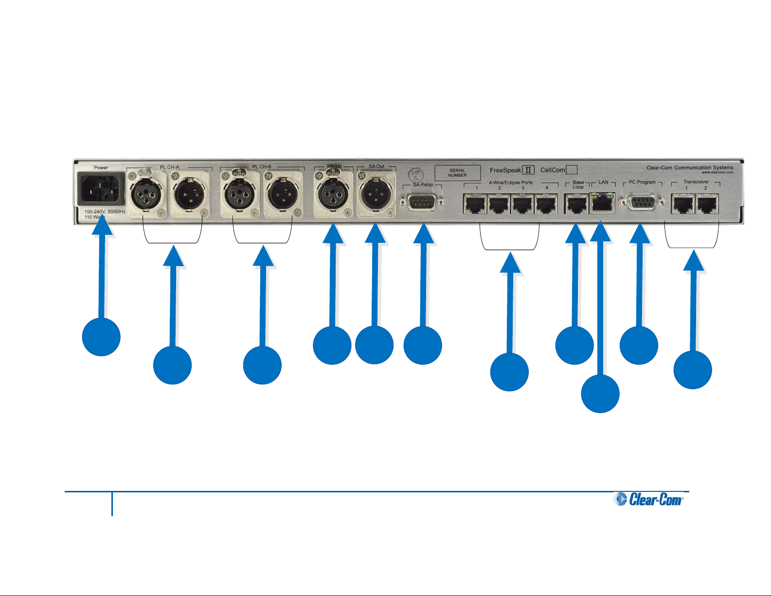
4.1 Understanding the Back-Panel Connectors
Figure 4-1 FS II Base station Back Panel
25
FreeSpeak II User Guide
Page 26
Key to FS II Base stati on rear panel
Feature
Description
A
Power connector
B
Partyline channel A connectors
3
Earphone ground
4
Earphone
C
Partyline channel B connectors
These connectors are the same as the the partyline channel A connectors.
D
Program input.
The 3-conductor AC power connector and universal power supply accepts
voltages from 90 to 250 volts, at 50/60 Hz. Power consumption is 80 watts.
The FS II Base station provides two pairs of partyline connectors, labeled
“Channel A” and “Channel B.” Each pair of female and male 3-pin XLR
connectors joins a channel of partyline intercom to the FS II, allowing
communication between the wired partyline equipment and FS II wireless
beltpacks. Input and Output level control is set via the front-panel display
programming.
The second connector of each pair is a loop-through, so that the user can
continue the connection to another FS II Base station or to another partyline
beltpack or station. This connector auto-detects a connection with a powered
partyline channel (30-VDC on Pin 2), and the Base station’s internal 200-ohm
partyline termination and DC voltage to power PL beltpacks is not activated.
Alternatively, when a wired, unpowered partyline beltpack (up to four) is
connected to PL CH-A with standard two-conductor shielded microphone cable,
the Base station engages the 200-ohm termination and supplies 24-VDC to the
beltpack(s) – allowing them to operate and communicate with the wireless
beltpacks in the system.
Pin Function
1 Mic ground
2 Mic +
Table 2-1: Headset socket pin out
This female 3-pin XLR connector accepts a line-level audio signal from an
outside source such as a mixing console or audio player. It is transformerisolated. Level adjustment is done via the front-panel display programming. The
program input can be assigned as an IFB source from the front panel.
26
FreeSpeak II User Guide
Page 27

Key to FS II Base stati on rear panel
Feature
Description
E
Stage announce output
F
G
Four-wire m atrix ports
H
Base loop connector
I
J
monitoring of the system configuration. It functions as a serial port.
K
should be fitted at the Base station end of the CAT-5 cable. Position the ferrite
This male 3-pin XLR connector allows a line-level audio signal, typically from
wireless beltpacks or 4-Wire sources, to be sent to a paging system or other
audio system. It is transformer-isolated. Level adjustment is done via the frontpanel display programming. More than one audio source at a time can be routed
to the Stage Announce, with the audio being combined to give a single audio
output.
Stage announce relay
This DB-9 male connector provides a relay closure that is triggered
simultaneously with the SA Output. The relay may be used to open an audio
pathway for the signal from the SA Output, or could also be used to activate a
light or lock or some other device. The relay may be wired for normally closed or
normally open operation, and the signal appears on pins 1 & 6 or 2 & 6. It is
rated to a maximum of 30-VDC at 1 amp.
These four RJ-45 connectors can connect four full-duplex (input pair and output
pair) audio connections from a 4-wire communications device, digital matrix
intercom, or similar – making them available to the wireless beltpacks. Any of
the 4-wire ports or the program input can be assigned as IFB sources from the
front panel.
Each of these connectors has its own time slot, and can be addressed
separately from a beltpack, or combined with other beltpacks and rear-panel
connectors in a group. Level adjustment is done via the front-panel display
programming.
The connector has no function in FS II.
LAN connector
This RJ-45 connector allows the Base station to be connected to a LAN for
system software upgrades and configuration downloads from the Configuration
Editor. It is a 10BaseT Ethernet port.
PC connector.
This female DB-9 connects to a PC computer for firmware updates and
Transceiver connectors
These two RJ-45 connectors connect the Base station to two remote FS-TA
transceiver/antennas or antenna splitters.
Each wired transceiver/antenna communicates with five wireless beltpacks.
Each antenna splitter provides connection for five transceiver antennas,
providing communication with up to a maximum of 10 beltpacks depending
upon available bandwidth.
To meet FCC emissions requirements a ferrite must be fitted on any CAT-5
cable plugged into either of the two ports labeled “transceivers.” The ferrite
27
FreeSpeak II User Guide
Page 28

Key to FS II Base stati on rear panel
Feature
Description
as close to the Base station as possible. A suitable ferrite is available from
Wurth, part number 742 711 32.
Pin
Description
2
Power
4.2 Connecting to partyline intercom systems
Up to two channels of partyline intercom can be connected to the FS II Base station. The
descriptions below will discuss connections with Clear-Com and compatible partyline, RTS
partyline, the ability of FS II to power up to four Clear-Com partyline beltpacks by itself, and
the front-panel settings associated with these partyline connections.
Using the front-panel display and rotary encoder, the user may go into the PORTS menu,
select the desired partyline channel, and create a five-character alphanumeric label for it. This
is the label that would then appear on any beltpacks to which that partyline connect ion was
assigned for communications. In the GROUPS menu, the partyline connection can be
assigned as a member of any of the groups, as desired.
4.2.1 Clear-Com and compatible partyline
Clear-Com and Clear-Com-compatible wired partyline intercoms connect to the PL CH-A and
PL CH-B connectors in a similar manner to connecting beltpacks or remote stations to the
intercom line. Typically that wired intercom connection would have a 30-VDC current on Pin 2,
coming from a main station or an intercom power supply. The second connector in the pair
may be used as a loop-through to go to other wired partyline stations or beltpacks, or to a
second FS II Base station. The pinout for partyline connector is shown in Table 4-1.
1 Ground (shield)
3 Audio
Table 4-1 Partyline pinout
4.2.1.1 To connect partyline equipment to the Base station
1) Check that the partyline LED on the front-panel is out, which indicates that the
partyline connection is disabled from the Base station.
2) Connect, and if appropriate, power up, the external partyline equipment.
3) Enable the partyline by pressing the “enable” button on the Base station’s front panel.
The Base station detects power and termination settings when the partyline is enabled by
pressing the “enable” button on the Base station’s front panel, or when the Base station is
powered up after having enabled the partyline. The Base station remembers that the partyline
is enabled when it powers up.
28
FreeSpeak II User Guide
Page 29

When the FS II Base station detects a wired partyline being connected with 30 VDC on Pin 2,
it does not enable the 24-VDC power supply that the FS II Base station supplies to the
connector to support a handful of locally connected wired partyline beltpacks. The Base
station then appears to the wired partyline system as a remote station.
The first call to a Partyline channel A or B results in the call alert and subsequent ones do not
give any further alerting unless the Partyline channel buttons on the Base station are toggled.
This prevents all calls giving alerts when this is not necessary.
4.2.2 Connecting directly to Clear-Com partyline beltpacks
PL CH-A and PL CH-B have the ability to directly support up to four Clear-Com RS501/601/701 partyline beltpacks each, without any other connection to a wired partyline
system. This feature gives the convenience of being able to add a few wired beltpacks when
needed to an FS II installation.
Connect a standard two-conductor shielded microphone cable to the PL CH-A connector, and
then connect it to a Clear-Com single-channel partyline beltpack. Enable the partyline and the
Base station will enable the required 200-ohm termination, and will supply 24-VDC to Pin 2 to
power the beltpack(s)
It is possible to daisy-chain up to four beltpacks, or use an intercom XLR splitter at the Base
station to feed microphone cables connected to the individual beltpacks. Because it is a 24volt rather than a 30-volt current, the maximum length of cable that can be connected (the
sum of all of the runs) will be shorter than what is expected with the standard partyline
voltage. Do the same with PL CH-B to support an additional four beltpacks.
4.2.2.1 To connect to the partyline
1) From the main menu, scroll to PORTS and select by pressing the setup/enter
encoder in.
2) Scroll to PLCHA or PLCHB and press to select.
The SELECTED PORT screen appears.
3) Scroll to and select CALLS.
The CALL DESTINATION screen appears.
4) Select the port or group to be connected to the partyline by scrolling to it and
pressing the rotary encoder. Doing so creates a route to the selected destination—
this port or group can now hear the activity on the partyline.
Note: This option can also be set to NONE.
5) Select TYPE from the menu.
6) Select either Clear-Com, Drake, or RTS.
7) The Base station automatically sets the termination, audio levels, and call signaling
options for the selected partyline system.
Note: The Base station does not detect the RTS call signal.
29
FreeSpeak II User Guide
Page 30

8) If the changes are saved the route will be reinstated on power up.
Note: Suggested settings for a partyline connection are that the VOX should be set to -26dB, the
gain output to -6dB and the input to 0dB.
4.2.3 Connecting to an RTS™ wired beltpack
FS II can only transmit and receive audio from channel 2 of an RTS wired beltpack. Connect
using a standard XLR cable. Ensure that the partyline type is set to “RTS” using the menu on
the Base station before enabling the partyline. See the chapter “Programming a System from
the Base station” for more information.
Warning: Previous versions of this manual described a cable which would allow access
to channel 1 of a dual channel RTS beltpack. DO NOT attempt to use a cable
like this as it could result in damage to the FS II Base station.
4.2.4 Front-panel adjustments for partyline connections
To connect the partyline channels to FS II and make the communication available to the rest
of the system, press the CH-A and/or CH-B enable switches. The LED will light, and the
connection is made. To disconnect the partyline connections, press these switches again. The
switch may be “locked” in the SYSTEM menu so that the partylines may not be disconnected.
Because partyline intercom does not have global level control on a channel, input and output
level controls are provided via the front panel programming. Scroll to PORTS on the main
display screen and press the rotary encoder to select. Scroll to PLCHA or PLCHB and press
to select. Select LEVELS, then select the input or output level. This notation is relative to the
Base station–input level refers to the level at which everyone else hears the partyline, and
output level refers to the level at which the users on the partyline channel hear everyone else.
Use the rotary encoder to adjust the numerical level—clockwise to increase the level and
counter-clockwise to decrease the level.
Make the estimated changes in level and press the rotary encoder to save the changes. Test
the levels between the partyline and FS II beltpack, and make additional changes as needed.
When the levels are set as desired, press to select and the display will go to the previous
INPUT/OUTPUT screen. When both are adjusted, select BACK on each screen until the main
screen is displayed.
Users connected to the Base station can be forced to listen to the activity on the partyline by
initiating a “call”.
For more information on programming the Base station, see the chapter “Programming a
System from the Base station”.
4.2.5 Troubleshooting partyline connections
4.2.5.1 Reducing FS II beltpack echo when talking to a analogue partyline
If the Base station and beltpack are not set up correctly the FS II user will experience an echo
when talking to a partyline (either directly or via a group or a wireless partyline). The echo is
caused by either local audio coupling in the headset due to the microphone gain being set too
high or audio reflections from the partyline that can minimized by setting a VOX gate on the
partyline and the partyline being auto nulled. An FS II system has a built-in microphone gain
control, but a VOX gate level can also be set in the configur ation editor (see next section).
30
FreeSpeak II User Guide
Page 31

4.2.5.2 Include the partyline channel inside a wireless partyline group
It is recommended that when connecting to an analogue partyline system that the user
includes the wireless partylines (WPL). The WPLs reduce the variation in audio levels heard
when talking to analogue partylines. The WPLs are created in the configuration editor in a
similar way to a user creating a group.
4.2.5.3 How to set the VOX gating level on the partyline connected to the Base station
Figure 4-2 VOX Gating Level on partyline connection
The VOX gate allows the user to set limits to the audio that will be passed from the partyline to
the Base station mixer; by setting the VOX level at the correct level the user can cut the audio
reflections (which cause the echo) from the partyline when a wireless beltpack user speaks.
This is achieved when the VOX level is set above the audio level of the reflections, thus
allowing a partyline user’s voice to pass through the VOX gate in the Base station mixer but
the VOX gate will reject the audio reflections.
Note: If both the partyline user and the FS II user speak at the same time, the FS II user may hear
the echo as the audio reflections piggy back the partyline audio.
31
FreeSpeak II User Guide
Page 32

Party-line A
Nulling
circuit
-15dB
-30dB
The reflections fr om the party-li ne get delaye d by the base sta tion
encoding, decoding and the DEC T stack which c aus es the echo.
V2.0 VOX gate
set to -26db
0dB
Party-line A
Nulling
circuit
-15dB
-30dB
V2.0 VOX gate
set to -26db
-20dB
Party-line A
Nulling
circuit
-5dB
-20dB
The reflection from the party-li ne c an be remove d by us ing the
new V2.0 VOX gate functionality therefore removing the echo.
But if the audio volume is inc r eased eit her by shouting or incre as ing
the mic ga in the party-line reflec tions will ret ur n, due to the VOX gate
set at a lower level.
Figure 4-3 VOX Gate Setting Examples
Note: If the FS II beltpack users shouts or increases the microphone gain into the beltpack the echo
might return if the audio reflects are above the VOX gate level.
4.2.5.4 Auto null the partyline channel at the Base station
Partylines connected to the Base station can be auto nulled by first enabling partyline channel
by pressing the partyline button on the front of the Base station.
The auto nulling is then activated by pressing and holding the enable partyline button. The
Base station will go then into an auto null routine.
4.3 Wireless partyline
The FS II Base station provides five wireless partyline groups which allow up to twenty eight
members to be connected together in a conference call. The beltpack keys assigned to the
wireless partyline group are assigned as dual talk and listen and partylines connected to the
group are assigned as talk and listen.
When a beltpack or partyline talks to a wireless partyline group the talk signal from the
beltpack or partyline is subtracted from the listen signal to remove the sidetone resulting from
the user’s voice being looped back in the conference audio, leaving only the audio from other
members.
32
FreeSpeak II User Guide
Page 33

Wireless Party Line
Group
(WPLG)
Auto
Nulling
Party Line
Channel A
(PLCHA)
BP1
BP2
Audio from
BP1
Audio to BP1
Audio from
BP2
Audio to BP2
Audio from
Party Line A
Audio to
Party Line A
Wireless Party Line
Group
(WPLG)
Party Line
Channel A
(PLCHA)
BP1
BP2
Audio from
BP1
Audio to BP2
Audio from
Party Line A
Audio to
Party Line A
BP3
Audio to BP3
Figure 4-4 Wireless partyline Audio Flow
This facility allows conferencing over a large area between a mix of beltpacks, partyline
stations and Eclipse system panels through an FS II Base station.
FS II beltpacks can only connect to a wired partyline via a wireless partyline. Therefore in
order to allow beltpacks to talk to each other and a wired partyline a wireless partyline must be
set up that includes the wired partyline (PLCHA or PLCHB) and the beltpacks (see Figure 4-5
Connecting beltpacks to a wired partyline). This ensures that the audio on the beltpacks is the
talk audio and not the sidetone audio.
Figure 4-5 Connecting beltpacks to a wired partyline
4.4 Connecting to 4-Wire and digital matrix intercom
Up to four channels of 4-wire/digital matrix intercom can be connected to the FS II Base
station. The descriptions below will discuss connections with Clear-Com Matrix Plus digital
matrix, Clear-Com Eclipse digital matrix, other brands of digital matrix intercoms, other 4-wire
audio devices, and the front-panel settings associated with these 4-wire connections.
4.4.1.1 To connect the Base station to a matrix port:
1) Scroll to PORTS on the main display screen and press the rotary encoder to select.
33
FreeSpeak II User Guide
Page 34

2) Scroll to 4-WIRE and press to select.
Pin
Description
3
Audio Output +
6
Audio Output -
8
Not used
3) Scroll to CALLS and press to select.
4) Select the port or group to create an audio path to and press to select. Doing so
creates a route to the selected destination—this port or group can now hear the
activity on the partyline.
Note: This option can also be set to NONE.
5) Once the changes have been saved, the route will be reinstated on power up.
Note: Call signalling is not currently supported on 4-wire connections.
In the GROUPS menu, the 4-wire port can be assigned as a member of any of the groups, as
desired.
4.4.1.2 4-Wire Pinout
The pinout for the RJ-45 4-wire port is shown in Table 4-2 FS II Base station 4-wire pinout.
1 Not used
2 Not used
4 Audio Input +
5 Audio Input -
7 Not used
Table 4-2 FS II Base station 4-wire pinout
4.4.2 Connecting to Clear-Com matri x p lus
The connection between a Matrix Plus digital intercom port and an FS II 4-wire port is
accomplished with a standard 4-pair straight-throug h C AT-5 data cable with RJ-45 connectors
on both ends. In the current generation of FS II, the audio input and audio output pairs are all
that will be used.
In the Matrix Plus PGM-WIN configuration software, set the matrix port that is connected to
the FS-BASE Base station 4-wire port to “4-Wire”. If the label of this FS II 4-wire port is to be
put onto more than one intercom panel within the matrix system, and any and all people who
have activated a talk/listen to that port are to be able to hear each other, as well as hearing
the person talking to them from the FS II wireless beltpack, also check “Partyline Enable” for
that 4-Wire connection in the configuration software.
34
FreeSpeak II User Guide
Page 35

Within the FS II Base station configuration software, the user can adjust the input and output
Pin
Function
1
Data Tx+
3
Audio Out+
6
Audio Out–
level for that port. Alternately, the input and output levels can be adjusted on the FS II Base
station for the particular 4-wire port, using the front-panel display. Repeat the procedure for
each FS II 4-wire port that is connected with the Matrix Plus system.
Note: FS II does not currently generate a call signal to the Matrix port.
4.4.3 Connecting to Clear-Com Eclipse digital matrix
The procedure to connect between an FS II 4-wire port and the Eclipse digital matrix is similar
to that of Matrix Plus 3. An identical connection is made with 4-pair straight-through CAT -5
cable between an Eclipse port and the FS II port.
Within the Eclipse Configuration System software (EHX) or ECS 5.2, set the port to “Direct.”
This will allow intercom stations in the Eclipse system to converse with the FS II Base station
and beltpacks. Because there is not a “Partyline Enable” within Eclipse, if several users of
intercom stations connected with Eclipse need to hear each other as well as the wireless FS II
beltpack, another procedure will need to be added. Within the configuration software, the user
would create a new partyline label, with members including the desired intercom stations and
the particular FS II 4-wire port. That label would then be assigned to a key on each of the
intercom stations, allowing connection with the FS II 4-wire port and the other members of the
new partyline.
Within the FS II Base station configuration software, the user can adjust the input and output
level for that port. Alternately, the input and output levels can be adjusted on the FS II Base
station for the particular 4-wire port, using the front-panel display. Repeat the procedure for
each FS II 4-wire port that is connected with the Eclipse system.
4.4.4 Connecting with other di git al mat rix intercom systems
Because FS II features standard 4-wire ports, with an input pair and an output pair, virtually
any 4-wire signal can be connected with it. Make sure to properly match the input and output
pairs between the digital matrix port and the FS II 4-wire port (see diagram below).
The pinouts for the first two 4-wire ports contain both audio and data connections, though the
data connections are not currently used. Those pinouts are shown in the following table.
2 Data Tx–
4 Audio In+
5 Audio In–
7 Data Rx+
35
FreeSpeak II User Guide
Page 36

8 Data Rx–
Table 4-3 Pinouts for connecting to other digital matrix intercom systems
The remaining two 4-wire connections are audio only, and the data connections are
unterminated (see Table 4-2 FS II Base station 4-wire pinout).
Within the configuration software of the other digital intercom system, configure its connected
port to 4-wire or similar. Adjust the input and output levels either at matrix side or within the FS
II front-panel display for the particular FS II 4-wire port.
4.4.5 Connecting with other 4-wire devices
Various other 4-wire audio devices can be connected with FS II. The Clear-Com EF-701M 4wire interface can be used to attach additional partyline channels to FS II, converting them
from partyline on the wired side to 4-wire on the FS II side.
The Clear-Com IF4W4 interface can be used similarly. The audio input side of the FS II 4-wire
connectors could be used for additional program or other audio inputs that could then be
accessed by FS II beltpacks. The audio output side of the FS II 4-wire connectors could be
used to route an FS II wireless beltpack user’s voice out of the system for paging or other
reasons, similar to the SA OUT connector.
When using the FS I I 4-wire ports in this way, make sure that proper connections are made
between FS II and the other device. Adjust the input and/or output levels either at the 4-wire
device or within the FS II front-panel display for that particular 4-wire port.
4.5 Connecting to a program audio source
FS II can connect with a program audio source, making it accessible to be assigned by itself
to a communication path to one or more FS-BP wireless beltpacks, or to be added to a group
with other communications and assigned to beltpacks. Using the two separate rotary encoder
volume controls on the beltpack, the user can monitor the program on one control while
talking and listening on an intercom channel with the other.
The balanced female 3-pin XLR connector accepts a standard audio signal from a mixing
console or similar, with Pin 1 ground, Pin 2 audio hot (+), and Pin 3 audio cold (-).This
connector is transformer-isolated.
To make the program input signal available to the system, the front-panel PRGM enable
button must be activated/on. The red LED above it will light, indicat ing that it is now available.
This front-panel switch may be “locked” to prevent accidental disengagement, using the front
panel display.
Using the front-panel display and rotary encoder, the user may select PORTS and give the
connector a five-character alphanumeric label. The user may assign that program input by
itself to a beltpack using the BELTPACKS menu, or use the GROUPS menu to assign the
program input to any group or wireless partyline. Program input can be assigned to multiple
groups or wireless partylines using the GROUPS menu.
4.6 IFB configuration
One of five FS II Base station inputs can be defined as a source for an IFB. These inputs are
the Program Input and the four 4-Wire ports. All the 4-Wire ports, partyline channels,
beltpacks, wireless partylines and stage output can be defined as IFB destinations.
36
FreeSpeak II User Guide
Page 37

Up to ten IFB key configurations can be set up that group together an IFB source and a
IFB Source
IFB Destination
IFB Talks
All beltpacks
number of IFB destinations and set the dimming level for that IFB key configur ation.
Program Audio Four-wire 3
All beltpacks
Four-wire 4
All beltpacks
Four-wire 3 Four-wire 4
Four-wire 4 Four-wire 3
All beltpacks
All beltpacks
All Beltpacks
Table 4-4 IFB key configurations
An IFB talk is a panel or beltpack with a key set up to talk to the IFB key configuration.
Whenever an IFB talk key is pressed the audio from the IFB source to the IFB destinations
configured in the IFB key configuration is dimmed by the set amount and the audio from the
IFB talk is heard by all the IFB destinations set up in that IFB key configuration.
4.7 Connecting to the stage announce output
Figure 4-6 IFB Audio Path
The IFB source audio will be dimmed on the IFB destinations for as long as the IFB talk key is
active. When the IFB talk key is released the IFB source audio to the destinations will return to
normal level.
The stage announce feature allows a talker to route their voice to an external paging system
or other audio destination by pressing one of the rotary encoders to which the SA OUT
connector is assigned. The adjacent SA RELAY is simultaneously triggered. One beltpack
user at a time may use this feature, though the capability may be assigned to any or all of the
wireless beltpacks, as desired.
37
FreeSpeak II User Guide
Page 38

Connect a microphone cable to the male 3-pin XLR connector on the rear of the FS II Base
Pin
Function
1
Normally Closed
3
5
N/C
8
N/C
2
3
station, and connect the other end to the external audio system. When the output is activated,
the beltpack user’s voice will be sent at line level to the audio system. The audio output
ceases when the beltpack user stops pressing the rotary encoder; it is good practice to make
sure that any rotary encoder to which the SA OUT is assigned is set to momentary/nonlatching mode.
2 Normally Open
N/C (no
connection)
4 N/C
6 Pole
7 N/C
9 N/C
Table 4-5 Pin assignments for stage announce connector
The associated SA RELAY can be assigned to open an audio route for the paging or
announcement, or can be assigned to initiate any other event such as turning on a light or
activating a lock. It is rated at a maximum of 30 VDC at 1 ampere. The relay can be wired to
be either normally open or normally closed, using the pinout information in Table 4-5 Pin
assignments for stage announce connector .
4.8 Connecting to a PC
4.8.1 Connecting using the serial port
The PC serial port on the rear of the FS II Base station is mainly used for firmware version
upgrades of the system.
A specially wired cable is required for these updates, consisting of two 9-pin D-type
connectors for the PC and the FS II ends. On the FS II end, a male 9-pin D connector is used,
and is wired as follows in relation to the D connector pins on the PC end. Pin 2 goes to pin 3,
pin 3 goes to pin 2, and pin 5 goes to pin 5; in other words, the data Tx and Rx lines on pins 2
and 3 are reversed. Those are the only wiring connections on the FS II end of the cable.
PC Connection (9-pin F) Base station (9-pin M)
1 N/C
3 2
38
FreeSpeak II User Guide
Page 39

4 N/C
6
N/C
9
N/C
PC Connection (9-pin
BELTPACK (3.5 MM
2
tip
5
screen
7
N/C
8
N/C
5 5
7 N/C
8 N/C
Table 4-6 Pinout for cable to upgrade Base station firmware
On the PC end, a female 9-pin D connector is used. Make sure that the data connections of
pin 2 to pin 3 and pin 3 to pin 2 are followed, and that pin 5 goes through to pin 5. Then short
pins 1, 4, 6, and 8 together on the PC end of the cable. The cable will now be ready to use
with the any upgrade files from the factory. Table 4-6 Pinout for cable to upgrade Base station
firmware gives the pin configuration for this cable. Table 4-7 Pinout for cable to upgrade
beltpack firmware shows the pin configuration for the cable used to upgrade beltpack
firmware.
F)
1 N/C
3 ring
4 N/C
6 N/C
9 N/C
Table 4-7 Pinout for cable to upgrade beltpack firmware
4.8.2 Connecting using the L AN port
This connection is used for rapid firmware updates, as well as in the future for system
configuration and intelligent connection with the Eclipse digital matrix. It is wired as a standard
Ethernet connection.
JACK)
The Base station has a fixed IP address. This can be found by selecting SYSTEM and then
INFO from the front-panel display menu. Refer to the chapter “FS II Toolkit” for more
information on using the LAN port to upgrade firmware.
39
FreeSpeak II User Guide
Page 40

4.9 Connecting to transceiver/antennas
4.9.1 Connecting one transceiver/antenna directl y to a transceiver port
A transceiver/antenna connects to the transceiver port on the FS II Base station using a
standard 4-pair CAT-5 data cable with RJ-45 connectors. It may be located up to 1,000
metres from the Base station if 24AWG cable is used or for 500 metres if 26AWG cable is
used creating a coverage area for five FS-BP wireless beltpacks in that location. The port is
able to provide the required power to the transceiver/antenna at a distance of up to 300
metres (approximately 900 feet); beyond that distance, the FS-TA transceiver/antenna must
be locally powered via its in-line external universal power supply.
Note: It is recommended that shielded CAT-5 cable is used.
To know that a transceiver/antenna is active, observe the green power LED and the yellow
signal LED on the face of the unit where the RJ-45 connector is connected. Both must be lit.
Also, wireless beltpacks in the vicinity of the active transceiver/antenna will be connected to
the system and their displays will show labels and other information.
Using both transceiver ports, a Base station may be connected with up to two
transceiver/antennas via a direct connection with the Base station. For the best, most reliable
coverage, it is advisable to use a minimum of two transceiver/antennas in any installation,
positioned in different locations in the coverage area. When more antennas are requi red to
support a larger coverage area or more wireless beltpacks, an antenna splitter will need to be
introduced between the Base station and the transceiver/antennas.
Note: In some situations, particularly in outdoor venues, interference from non-DECT sources can
severely reduce the range of the system. In these cases we recommend a site survey as
described in Chapter 8, “Installing a System”.
4.9.2 Connecting transceiver/antennas with a splitter (PD2203 )
A splitter (PD2203) will connect up to five transceiver/antennas to one of the transceiver ports
on the FS II Base station, creating up to five coverage zones that can be overlapped to make
large areas where FS-BP wireless beltpacks can have continuous coverage. The use of the
splitter also extends the distance that the transceiver antennas can be located from the Base
station to 2,000 metres (6,400 feet) if 24AWG cable is used or 1.000 metres (3,200 feet) if
26AWG cable is used (assuming the same cable type is used to connect the antenna to the
splitter and the splitter to the Base station).
Note: It is recommended that shielded CAT-5 cable is used.
For example, a splitter can be used to connect to an FS II Ba se statio n that is located in a
production truck outside an arena or stadium, with a single CAT-5 cable going to the splitter
which is then located just inside the stadium. From that splitter, up to five transceiver/antennas
are distributed throughout the stadium to create wide coverage – each with a run of CAT-5
cable back to the splitter. A similar arrangement may be used in a large theatre or performing
arts facility.
The connection between a transceiver port on the FS II Base station and a PD2203 splitter is
accomplished with standard 4-pair CAT-5 data cable with RJ-45 connectors. It is connected to
the port labeled MATRIX on the splitter. This cable can be as long as 1,000 metres (3,200
feet) if 24AWG cable is used or 500 metres (1,600 feet) if 26AWG cable is used. The splitter
must be locally powered via its DC IN connector, using the in-line external universal power
supply. The RJ-45 ports on the splitter labeled “1” through “5” are the connections to the FSTA transceiver/antennas. Transceiver/antennas connected to the splitter can be powered at a
40
FreeSpeak II User Guide
Page 41

distance of up to 300 metres (900 feet); beyond that distance they will need to be locally
powered.
4.9.3 Powering an antenna or antenna splitter
Provision of 24 VDC power to an FS II antenna is done as follows:
• Connect the antenna to a 150/UNI-DIN power supply unit through the 4-pin DIN connector
at the antenna.
• Connect the antenna to an antenna splitter which is powered by a power-supply unit.
The preferred method is to connect the antenna to a powered antenna splitter, as illustrated in
Figure 4-9 Powering an antenna splitter . An antenna splitter distributes power to all antennas
connected to it. A single power-supply unit can power the maximum 5 antennas. However,
maximum cable lengths will be reduced.
Figure 4-7 Recommended antenna and splitter powering schemes and cable lengths, psu at
splitter only
Figure 4-8 Recommended splitter and antenna powering schemes and cable lengths, psu at
splitter and antenna/transceiver
Figure 4-9 Powering an antenna splitter
41
FreeSpeak II User Guide
Page 42

5 Operating the Base stat ion
5.1 Introduction
The FS II Base station provides all of the intelligence and signal routing for the FS II digital
wireless intercom system. The Base station is a full-duplex digital matrix communications
system, with virtual “ports” for the wireless beltpacks rather than physical ports.
In its memory, the Base station contains all of the labels and communications paths assigned
to each beltpack, and this information is sent to the beltpacks via the transceiver/antennas as
soon as they are switched on and recognized by the base.
The Base station also functions as the interface between wired and wireless communication
devices. The two partyline intercom connectors, four 4-Wire connectors, and program
input/stage-announce output each have their own full-duplex time slot. They can be labeled,
added to communication groups, and assigned to beltpacks as desired. Additionally the
program input or one of the four 4-Wire connections can be assigned as IFB sources on the
Base station.
42
FreeSpeak II User Guide
Page 43

A B
C
D
E
F
G
H
I
J
K
L
5.2 Understanding Fron t-Panel Operation
Figure 5-1 FS II Base station Front Panel
5.2.1 Call Channel A
Pressing buttons (B) & (D) together will send a call signal to the port, group or wireless partyline (WPL) assigned under headset channel
A. The Talk button (B) must be engaged momentarily before the Call/Reply (D).
5.2.2 Call Channel B
Pressing buttons (E) & (D) together will send a call signal to the port, group or WPL assigned under headset channel B. The Talk button
(E) must be engaged momentarily before the Call/Reply (D).
43
FreeSpeak II User Guide
Page 44

Key to FS II Base stati on front panel
Feature
Description
A
Headset connector
B
C
Headset channel A talk control/listen control
D
E
F
G
Partyline channels A and B
The 4-pin male XLR-type headset socket connects to Clear-Com headsets and
other headsets with 4-pin female connectors. This headset connector is for the
on-board two-channel intercom, with controls just to the right of the connector.
The channel A talk switch and associated light, and listen level encoder, allow
full-duplex conversations with any FS II wireless beltpacks or other
communications systems wired to the rear of the Base station to which the onboard Channel A has been assigned. Assignments are done via the front-panel
programming.
The talk switch is momentary/latching, such that pressing it and holding down
will create a talk path that ends when the user releases the switch, while quickly
tapping it will latch the talk, and a second tap will release it. The LED lights red
when a talk is active.
Turning the listen level encoder clockwise will allow the user to hear the other
party’s voice, increasing the level to maximum when fully clockwise.
A/B reply button.
Pressing this button will reply to the last caller to call A or B.
Headset channel B talk control/listen control
The channel B talk switch and associated light, and listen level encoder,
function the same as the controls for Channel A.
The channel A and channel B enable switches and associated lights activates
the power only on the rear-panel to partyline intercom channels A and B.
Activating one or both of these switches enables the power to that party line but
does not affect the audio to the partyline which is always connected. These
switches may be “locked” via the front-panel SYSTEM programming menu so
that they may not be disengaged accidentally. See 6.21 Locking Front Panel
Enable Buttons.
If the button is held in for more than 8 seconds autonulling mode will be enabled
for the current partyline and the following message will be displayed:
“Release button to begin autonulling”
When the button is release the Base station will perform an autonulling on the
current partyline. On completion the following message will be displayed:
“Partyline A/B Autonulling complete”
The autonulling process is recommended on initial system set up and when the
partyine system has been changed.
44
FreeSpeak II User Guide
Page 45

Key to FS II Base stati on front panel
Feature
Description
H
Program audio enable switch
I
Antenna ready light display
J
Display screen
K
L
This latching switch makes any program audio signal that enters via the rearpanel line-level 3-pin XLR connector available to be assigned to wireless
beltpacks, either separately or mixed with communications groups. This switch
may be “locked” via the front-panel SYSTEM programming menu so that it may
not be disengaged accidentally..
These green LEDs, one for each of the ten antennas that the Base station will
support, light when an antenna is connected and ready.
.
The display screen shows all of the menus and programming options that are
available within the FS II system. The user can select a particular beltpack and
view all of its current talk/listen assignments, or see all of the current members
of a particular group. Via the screen and rotary encoder, labels (5-character
user names) can be created and/or changed, new members assigned to
groups, input and output levels adjusted, and so on.
Scroll/enter control
The setup/enter encoder is used to scroll through the various menu options
within the FS II Base station, in order to discover specific information regarding
users or to program communications routes and groups. Turning the encoder
clockwise scrolls display items toward the right, and turning the encoder counter
clockwise scrolls display items toward the left.
When a desired menu item is highlighted, pushing the setup/enter encoder
inward will select that item. The lists of available beltpacks and groups typically
span two or more screens, so when the highlight is at the leftmost or rightmost
part of the screen and the user continues to turn the rotary encoder in that
direction, the display will jump to the next screen selections (Example: in the
beltpack sections, the first screen shows beltpacks 1 through 5, and the second
shows 6 through 10.)
45
FreeSpeak II User Guide
Pressing and holding the setup/enter encoder for more than three seconds will
return the display to the battery monitor.
Power switch
The power switch will turn the FreeSpeak Base station on and off.
Page 46

6 Programming a system from the Base station
This chapter describes how to program the FreeSpeak II system using the Base station front
panel controls and menu. It contains the following sections:
• Introduction
• Using the Base station’s programming menus
• Saving changes
• Changing beltpack labels
• Setting and changing port labels
• Setting and changing group labels
• Adding group members
• Beltpacks
• Assigning audio routes to a beltpack
• Setting the beltpack audio level
• Setting beltpack latching
• Over the Air (OTA) beltpack registration from the Base station
• Setting input and output port levels
• Setting port call destination
• Configuring a wired partyline
• Base station System Menu
• System
• Restoring the Defaults
• Antennas
• Setting the IP address
• Locking front-panel enable buttons
• Remote microphone kill
• Battery indicator
46
FreeSpeak II User Guide
Page 47

6.1 Introduction
An FS II system is programmed using the menus displayed on the Base station’s front panel.
Programming the system requires four basic steps:
1) Create individual names (“labels”) for the wireless beltpacks and for the wired
devices connected to the Base station. Use individual labels for building “point-topoint” communication paths.
Labels are composed of five alphanumeric characters. Labels can be created for users’
names (“John” or “Susan”), roles (“AUDIO” or “DIR”), or for connections (“PL_A” or “PL_B”).
Alternatively a device’s generic name can be used, which never changes. An example of a
generic name is “BPK01” for Beltpack 1. Generic names are always displayed on the
programming men u s.
2) Create names (“labels”) for groups. A group label is used when an FS II beltpack
needs to communicate with all members of a group simultaneously, as in a partyline.
Up to ten groups can be created, with five groups being standard groups and five
groups being wireless partyline groups. Up to fifteen members can be assigned to a
standard group and up to twenty eight members can be assigned to a wireless
partyline group.
A label can be customized to reflect the group’s function, such as “STG-A” for communicating
with the production staff on Stage A.
Alternatively the generic names assigned for the ten possible groups can be used. For
example, “GP#01” is the generic name for Group 1.
3) Assign members to the groups created. Group members are drawn from the
wireless beltpacks and from the wired devices connected to the Base station. A
group created from these devices functions as a partyline, in which all members of
the group can communicate simultaneously with all other members of the group.
4) Assign individual and grouped devices each FS II beltpack by using the programming
screens on the Bas e station’s fr ont panel. Each assignment creates a communication
route from the FS II beltpack to the selected device or group. Up to four
communication routes can be assigned to a beltpack.
These steps are discussed in more detail in the following sect ions.
6.2 Using the Base station’s programming menus
An FS II system can be programmed using the programming menus that appear on the Base
station’s front-panel display screen. The user navigates through the menus to select
programming options for the system.
Rotating the setup/enter encoder allows the user to scroll through the selections on the
screen. As the user scrolls through the menu items are highlighted on the screen. To select an
item as a new programming option, press the setup/enter encoder in, as if it were a
pushbutton, when the desired item is highlighted on the screen.
47
FreeSpeak II User Guide
Page 48

6.3 Saving changes
The changes are saved and applied automatically when changes are made to the unit’s
programming. Five seconds after the last time the setup/enter encoder was turned or pressed,
the front-panel display flashes to indicate that the changes are being saved and applied.
6.4 Changing beltpack labels
The first step in creating an FS II system is to create individual names (“labels”) for the
wireless beltpacks and for the wired devices connected to the Base stati on. Use individual
labels for building “point-to-point” communication routes.
6.4.1 To change a beltpack label
1) From the MAIN menu on the Base station’s front panel display, scroll to and select
BELTPACKS, as shown in Figure 6-1 From the MAIN menu, select BELTPACKS.
Figure 6-1 From the MAIN menu, select BELTPACKS
The AVAILABLE BELTPACKS menu appears, as shown in Figure 6-2 Available beltpacks
menu below. The first page shows the first five beltpack labels.
Figure 6-2 Available beltpacks menu
• The beltpacks’ generic labels BPK01 through BPK05 appear on the upper row, while
the labels given to the beltpacks appear just under the generic labels. At first both
upper and lower labels will have the same generic designations.
• To get to the second, third and fourth pages of beltpacks, scroll all the way to the
right of the screen, and then continue to scroll. The second, third and fourth pages
will be displayed showing beltpacks 6 - 10, 11 - 15 and 16 - 20 (BPK06 - BPK10,
BPK11 - BPK15, BPK16 - BPK20).
2) Scroll to and select the desired beltpack.
The next menu that appears gives the options for programming the selected beltpack, as
shown in Figure 6-3 First beltpack programming options menu.
Figure 6-3 First beltpack programming options menu
48
FreeSpeak II User Guide
Page 49

3) Scroll all the way to the right of the screen and continue to scroll. The second
beltpack programming options menu will be displayed.
Figure 6-4 Second beltpack programming menu
4) Scroll to and select LABEL from the menu.
A menu to edit the selected beltpack’s label appears, as shown in Figure 6-5 editing a
beltpack’s label. The current 5-character label appears, just under its generic name.
Figure 6-5 editing a beltpack’s label
5) Scroll to and select the alphanumeric character to be changed. A box appears
around the character.
6) Rotate the setup/enter encoder. As the encoder is rotated the entire range of
available characters appears, starting with upper-case characters, proceeding to
lower-case characters, then to digits, and finally to punctuation characters.
7) When the desired new character appears, press the setup/enter encoder to select it.
The box disappears, and is replaced by the solid highlight.
8) Repeat steps 4 through 6 for all the characters in the label that are to be changed.
9) When editing the label has been completed, select BACK to return to the
PROGRAMMING OPTIONS menu.
10) The changes are saved and applied automatically five seconds after the last time the
setup/enter encoder was pressed or turned. The front-panel display flashes to
indicate that the changes are being saved and applied.
11) The beltpack that has had a new label assigned to it should be power cycled to
ensure it is updated with the new label.
To edit another beltpack label, scroll clockwise to the BACK command and select the
beltpack. The AVAILABLE BELTPACKS screen appears. Select a new beltpack label to edit,
and repeat steps 2 through 9.
6.5 Setting and changing port labels
Port labels are created to identify the audio devices wired to the Base station’s rear panel
ports, such as partyline beltpacks, 4-wire devices, program sources, and stage-announce
outputs and relays.
49
FreeSpeak II User Guide
Page 50

6.5.1 To create a port label
1) From the Base station’s MAIN menu, scroll to and select PORTS (see Figure 6-6
Select “Ports” from the main menu).
Figure 6-6 Select “Ports” from the main menu
The first AVAILABLE AUDIO PORTS menu is displayed, as shown in Figure 6-7 First
available ports menu.
The first page of the menu shows the first 5 ports, starting with HDSTA (front-panel headset
A) and continuing through 4WIR3 (the third 4-wire connector on the rear panel), as shown in
Figure 6-7 First available ports menu.
Figure 6-7 First available ports menu
By scrolling all the way to the right, and then continuing to scroll, 4WIR4 through PRGRM
(program) will be displayed (Figure 6-8 Second available ports menu).
Figure 6-8 Second available ports menu
Note: The upper character of the pair is a generic label, while the lower character
is editable.
2) Select an audio port from the menu. A screen appears that gives the options for
programming the selected port, as shown in Figure 6-9 Port programming options
menu.
Figure 6-9 Port programming options menu
3) Select LABEL from the menu.
A menu to edit that port’s label appears as shown in Figure 6-10 Editing a port’s label.
50
FreeSpeak II User Guide
Page 51

Figure 6-10 Editing a port’s label
4) Scroll to and select the alphanumeric character to be changed. A box appears
around the character.
5) Rotate the setup/enter encoder. As the encoder is rotated the entire range of
available characters appears, starting with upper-case characters, proceeding to
lower-case characters, then to digits, and finally to punctuation characters.
6) When the desired new character appears, press the setup/enter encoder to select it.
The box disappears, and is replaced by the solid highlight.
7) Repeat steps 4 through 6 for all the characters in the label that are to be changed.
8) Select ‘BACK’ to save the label. The front-panel display flashes to indicate that the
changes are being saved and applied.
To edit another port label, scroll clockwise to the BACK command and select it. The
AVAILABLE AUDIO PORTS menu appears. Select a new audio port to edit, and repeat steps
2 through 9.
6.6 Setting and changing group labels
A group label is used when an FS II beltpack needs to communicate with all me mbers of a
group simultaneously, as in a partyline. The user can create up to ten groups. Five of these
can be standard groups with up to twelve members per group and five can be wireless
partyline groups with up to thirty members per group.
Group members can be individual beltpacks or wired devices connected to the Base station.
To form a group, the user must first create a name or “label” for the group, and then assign
members to the group.
6.6.1 To create a group label
1) From the main menu, select GROUPS. The first page of the AVAILABLE GROUPS
menu appears, as shown in The 5 standard group labels appear on the first page of
the menu. The generic labels GP#01 through GP#05 appear on the top row, and their
editable versions appear on the lower row. The default values are GRP01 through
GRP05.
Figure 6-11 Standard group labels
51
FreeSpeak II User Guide
Page 52

By scrolling all the way to the right, and then continuing to scroll, the wireless partyline groups
appear on the second page of the menu.
Figure 6-12 Wireless partyline group labels
The generic wireless partyline group labels WP#01 through WP#05 appear on the top row,
and their editable versions appear on the lower row. The default values are WPL01 through
WPL05.
2) From the AVAILABLE GROUPS menu, select a group label. A menu appears that
gives the options for programming the selected group, as in Figure 6-13 Select label
from the menu.
Figure 6-13 Select label from the menu
3) Select LABEL from the menu.
A menu to edit that group label appears, as shown in Figure 6-14 Group name edit menu.
Figure 6-14 Group name edit menu
4) Scroll to and select the alphanumeric character to be changed. A box appears
around the character.
5) Rotate the setup/enter encoder. As the encoder is rotated the entire range of
available characters appears, starting with upper-case characters, proceeding to
lower-case characters, then to digits, and finally to punctuation characters.
6) When the desired new character appears, press the setup/enter encoder to select it.
The box disappears, and is replaced by the solid highlight.
7) Repeat steps 4 through 6 for all the characters in the label that are to be changed.
8) Select ‘BACK’ to save the label. The front-panel display flashes to indicate that the
changes are being saved and applied.
In order to edit another group label scroll clockwise to the BACK command and select it. The
AVAILABLE GROUPS menu appears. Select a new group label to edit, and repeat steps 2
through 9.
52
FreeSpeak II User Guide
Page 53

6.7 Adding group members
When a group name or “label” has been chosen the user may then “populate” that group.
Group members are drawn from the individual wireless beltpacks and individual wired devices
connected to the FS II Base station. A group created from these devices functions as a
partyline, in which all members of the group can communicate simultaneously with all other
members of the group. A standard partyline group may contain up to fifteen members and a
wireless partyline group may contain up to twenty eight members.
Note: Headsets cannot be added to a wireless partyline type group by this method.
6.7.1 To assign members to a group
1) From the MAIN menu, select GROUPS. The AVAILABLE GROUPS menu appears.
2) Select the group to which members are to be added. The PROGRAMMING
OPTIONS menu appears, as shown in Figure 6-15 Group programming options
menu.
Figure 6-15 Group programming options men u
3) Select MEMBERS from the menu.
The MEMBERS menu appears, as shown in Figure 6-16 Adding members to a group. On this
set of pages, all of the Base station wired ports appear (HDSTA through PRGRM, “headset A”
through “program”), followed by the labels for all twenty FS II beltpacks. The menu header
displays the number of members currently in the group out of a possible maximum of twelve
members e.g. 4/12 for four members.
Figure 6-16 Adding members to a group
4) Scroll through the pages of this list to find the desired members for the group. When
a desired member is highlighted, press the setup/enter encoder to select that
member. A box appears around it.
5) To de-select a member that has already been selected, highlight that member and
press the setup/enter encoder. Pressing the setup/enter encoder effectively works as
a toggle switch, first selecting the item by putting a box around it, and then deselecting it and removing the box.
53
FreeSpeak II User Guide
Page 54

6) When all of the desir ed beltpack labels and Base station port labels have been
selected, scroll clockwise to BACK and select it to exit the selection process.
Continue selecting the BACK command until the desired screen is reached.
7) The changes are saved and applied automatically five seconds after the last time the
setup/enter encoder was pressed or turned. The front-panel display flashes to
indicate that the changes are being saved and applied.
To edit a group that already has members, go through the procedure above to reach the
member labels. Scroll through the list, using presses of the rotary encoder to select and deselect members. Exit as above, and save the changes in the system memory.
6.8 Beltpacks
The following steps have been completed in setting up the system:
• Created names (“labels”) for the FS II beltpacks and for the devices wired to the Base
station’s rear panel
• Created names (“labels”) for communication groups and assigned members to the each
group.
6.9 Assigning audio routes to a beltpack
The next step is to assign communication routes to the individual FS II beltpacks.
For this example, communication routes are assigned to the beltpack in position one—BPK01.
The procedure is identical for all remaining beltpacks.
8) From the MAIN menu, select BELTPACKS.
The AVAILABLE BELTPACKS screen is displayed.
9) Select the required beltpack. The BELTPACK menu is displayed. Scroll through the
screens to KEYS.
10) Select KEYS. The KEY EDITING screen appears,
11) A list of the audio routes and groups available for selection is visible. Select the
beltpack key to assign communication to (A, B, C or D).
(screenshot)
12) A screen appears with a list of available sources and destinations to assign to this
key. This list will include:
• Headset A and B
54
FreeSpeak II User Guide
Page 55

• 4 wire ports 1-4
• Stage announce
• Program feed
• Beltpacks 1-20
• Groups 1-5
• Wireless partylines 1-5
• Interruptible foldback (IFB) 1-10
Figure 6-17 Select the source/destination to assign to that beltpack key
13) Scroll through the list and select the desired source or destination to assign to that
beltpack key. A box appears around the selection and the next screen appears for
assigning the key type.
14) For some destinations and sources (headsets, stage and program announce,
beltpacks and IFB’s) the system will assign the feed to the beltpack key when you
press the setup/Enter rotary controller. You will be returned to the previous screen
and it will flash to show a change has been accepted by the system.
For other audio routes (4 wire ports, groups and wireless partylines) it will be
necessary to select a key assignment type. See step 8 below.
15) Select either talk (TLK), listen (LIS), talk/listen (T+L), dual talk/listen (DTL), forced
listen (FL) or talk/forced listen (TFL) for that key.
Figure 6-18 Key type menu
Note: For more information on audio route key types see 10.4.10 Key Assignment Types.
16) The display automatically returns to the screen for selecting the next key to program.
17) Select the next key and follow steps 4 through 6. Continue until sources and
destinations have been assigned to all desired keys on that beltpack.
Note: Keys C & D default to call keys for A & B respectively if not assigned.
To assign keys for another beltpack continue selecting the BACK command on each
successive screen until reaching the AVAILABLE BELTPACKS menu. Highlight and select the
next beltpack, and repeat the above procedures.
55
FreeSpeak II User Guide
Page 56

18) The screen will flash after a change has been made to show that it has been
accepted by the system.
6.10 Setting the beltpack audio level
1) From the MAIN menu, select BELTPACKS.
The AVAILABLE BELTPACKS screen is displayed ( Figure 6-2 Available beltpacks menu).
2) Select the beltpack for which audio levels are to be set. The BELTPACK menu is
displayed.
3) Select ‘LEVELS’. The beltpack levels editing menu is displayed, as shown in Figure
6-19 Beltpack levels menu.
Figure 6-19 Beltpack levels menu
4) Use the setup/enter encoder to select the input level to display the beltpack input
level setup.
Figure 6-20 Beltpack Input level setup
5) Use the setup/enter encoder to set the beltpack input level in the range -20dB to
+6dB by rotating it anticlockwise to reduce the level and clockwise to increase the
level. Press the setup/enter encoder to select the input level.
6) Use the setup/enter encoder to select the output level to display the beltpack output
level setup.
Figure 6-21 Beltpack output level setup
7) Use the setup/enter encoder to set the beltpack output level in the range -20dB to
+6dB by rotating it anticlockwise to reduce the level and clockwise to increase the
level. Press the setup/enter encoder to select the output level.
56
FreeSpeak II User Guide
Page 57

6.11 Setting beltpack latching
Beltpack latching determines whether the beltpack A and B latch when pressed so that the
user does not have to keep the button pressed to maintain an audio route, or are non-latching
so the audio route is only open when the button is pressed.
1) From the MAIN menu, select BELTPACKS.
The AVAILABLE BELTPACKS screen is displayed (see Figure 6-2 Available beltpacks menu).
2) Select the beltpack for which audio levels are to be set. The BELTPACK menu is
displayed.
3) Select ‘LATCH’. The beltpack latching menu is displayed, as shown in Figure 6-22
Beltpack latching menu.
Figure 6-22 Beltpack latching menu
4) Use the setup/enter encoder to select ‘NON-LATCHING’ or ‘LATCHING’ on the menu
and press the setup/enter encoder to set the latching status.
6.12 Over the Air (OTA) beltpack registration from the Base station
Before beltpacks can be used they must be registered to the Base station. There are a
number of ways of doing this, either OTA or via a USB cable using the configuration software.
For more information, see 3.4.1 Over the air (OTA) registrat ion of a beltpack from the
Base station for the procedure.
6.13 Setting input and output port levels
The settings at the Base station determine the input and output audio levels of a device
connected to a port. The user can adjust the levels from -20 to +6 dB.
6.13.1 Input level
The input level affects the volume of a signal coming into the Base statio n, for example from
the Stage Announce (STGAN) port. Adjusting this level will affect the volume of this channel to
ALL the users of the Base station.
• Setting the “input” level alters how loudly all users of the system will hear a channel; it is a
global volume control.
6.13.2 Output level
The output level refers to the signal output to individual ports.
57
FreeSpeak II User Guide
Page 58

• Setting the “output” level alters how loudly individual ports hear audio sources.
For example, to adjust the Stage Announce audio to head set A only, adjust the Output level
on that port (HDSTA). See instructions below.
6.13.3 To set the audio level for a port
1) From the MAIN menu, select PORTS. A menu of the available audio ports is
displayed.
Figure 6-23 Available audio ports menu
2) Select the port for which the audio levels are to be adjusted from the AVAILABLE
AUDIO PORTS menu. The SELECTED PORT menu will be displayed.
Figure 6-24 Selected port menu for level setting
3) Select ‘LEVELS’ from the next menu.
The EDITING LEVELS menu appears.
Figure 6-25 Port levels menu
4) Select ‘INPUT’ to display the input level setup menu.
Figure 6-26 Port input level setup
5) Rotate the setup/enter encoder clockwise or counter clockwise to increase or
decrease the input level in 1 dB increments.
6) When the desired audio level appears on the screen, press and release the
setup/enter encoder to select it,
58
FreeSpeak II User Guide
Page 59

7) The changes are saved and applied automatically five seconds after the last time the
setup/enter encoder was pressed or turned. The front-panel display flashes to
indicate that the changes are being saved and applied.
8) Select ‘OUTPUT’ to display the output level setup menu.
Figure 6-27 Port output level setup
9) Rotate the setup/enter encoder clockwise or counter clockwise to increase or
decrease the output level in 1 dB increments.
10) When the desired audio level appears on the screen, press and release the
setup/enter encoder to select it.
11) The changes are saved and applied automatically five seconds after the last time the
setup/enter encoder was pressed or turned. The front-panel display flashes to
indicate that the changes are being saved and applied.
In some cases, the audio paths must be re-made before the changes will take effect.
6.14 Setting port call destination
Partyline, 4-Wire, Stage Announce and Program ports can also have call destinations
configured. In this case any audio on the port will immediately be routed to the specified
destination which may be any of the other available ports. If the VOX trigger is set then audio
on this port will be routed to the destination when the specified threshold is exceeded.
1) From the MAIN menu, select ‘PORTS’. A menu of the available audio ports is
displayed.
Figure 6-28 Available audio ports menu
2) Select the port for which the call destination is to be set (excludes headset ports).
The menu for the selected port will be displayed.
Figure 6-29 Selected port menu for calls
59
FreeSpeak II User Guide
Page 60

3) Select ‘CALLS’ from the menu. The call destination menu will be displayed.
Figure 6-30 Port call menu
4) Use the setup/enter encoder to scroll through the available ports and select the
required destination port. It is possible to select the source port as the call destination
to create an audio loopback system. This may be used for audio testing purposes.
Figure 6-31 Port destination select menu
5) When the port is selected, the user is returned to Selected Port Menu for Calls
(Step 2). The screen will flash momentarily to indicate that the port change has been
accepted by the system.
6) The port destination can be cleared by repeating the process and selecting the
‘NONE’ entry.
If one of the headset ports (HDSTA, HDSTB) is selected the port menu is different in that
‘KEY’ is displayed rather than ‘CALL’. This indicates than in order to trigger an auto route from
the headset to the chosen destination the key on the Base station front panel should be used.
7) From the MAIN menu, select ‘PORTS’. A menu of the available audio ports is
displayed.
Figure 6-32 Available audio ports menu
8) Select the head set for which the call destination is to be set. The menu for the
selected headset will be displayed.
Figure 6-33 Selected port menu for calls
9) Select ‘KEY’ from the menu. The audio destination menu will be displayed.
60
FreeSpeak II User Guide
Page 61

Figure 6-34 Port call menu
10) Use the setup/enter encoder to scroll through the available ports and select the
required destination port. It is possible to select the source port as the call destination
to create an audio loopback system. This may be used for audio testing purposes.
11) The port destination can be cleared by repeating the process and selecting the
‘NONE’ entry.
6.15 Configuring a wired partyline
Before enabling a partyline from the Base station’s front panel the type of partyline must be
set on the Base station so that it can set the proper termination, gain level, and call signalling
for that system.
The three types of partyline systems are: Clear-Com, Drak e, and RTS.
6.15.1 To select the type of part yline system for a partyline port
1) Select PORTS from the main menu, then select PLCHA or PLCHB from the
AVAILABLE AUDIO port menu which appears.
(screenshot)
2) The port configuration menu is displayed. Scroll rightwards to display the second
page of the menu.
(screenshot)
3) Select TYPE. The first port type menu is displayed.
Figure 6-35 First partyline connection type menu
4) All the options on the first menu imply that the partyline port will have termination
enabled. If this is correct select either Clear-Com, Drake, or RTS. If the partyline port
should have termination disabled because the partyline is already terminated by
another device scroll rightwards to display the second partyline type menu.
61
FreeSpeak II User Guide
Page 62

Figure 6-36 Second partyline connection type menu
5) Select ‘OFF’ to disable partyline termination on the port. This will apply regardless of
the type of partyline connected to the port. For example if the partyline is connected
to an MS-702 master station with termination enabled the Base station termination
must be disabled.
6) The changes are saved and applied automatically five seconds after the last time the
setup/enter encoder was pressed or turned. The front-panel display flashes to
indicate that the changes are being saved and applied.
The Base station automatically sets the port’s termination, gain, and call signalling options for
the selected partyline type.
6.15.2 To configure the Noise Gate for a partyline port
The noisegate sets a cutoff level below which audio input is ignored in order to avoid
transmitting low levels of background noise. The noisegate can be set to a value in the range 70dB to -10dB when enabled.
1) Select PORTS from the main menu, then select PLCHA or PLCHB from the
AVAILABLE AUDIO port menu which appears.
2) The port configuration menu is displayed. Scroll rightwards to display the second
page of the menu.
3) Select GATE. The Noise Gate menu is displayed.
Figure 6-37 Partyline noisegate menu
4) Scroll to the ‘STATE’ option and press the setup/enter encoder to display the
noisegate state menu.
Figure 6-38 Partyline noisegate options menu
62
FreeSpeak II User Guide
Page 63

Scroll through the options to enable or disable the noisegate and use the enter function to
select the required state. The main noisegate menu will be redisplayed.
5) Select the level entry to display the partyline level setup menu.
Figure 6-39 Partyline noisegate trigger level
The vertical bar indicates the noisegate trigger level. Turning the setup encoder clockwise
increases the noisegate level (towards the maximum -10dB) and turning it counter clockwise
reduces the noisegate level (towards -70dB). The horizontal bar indicates the current input
audio level in real-time to assist in setting the noisegate level.
6) Select the ‘DELAY’ option on the noisegate menu to set the VOX off delay level. This
allows the operator to set a delay in milliseconds before audio is cut by the noisegate.
Figure 6-40 VOX delay setup
The VOX delay can be set to values between 50ms and 5000ms in 50ms steps. Turn the
Setup encoder clockwise to increase the delay and anticlockwise to reduce the delay.
6.15.3 To configure the levels for a partyline port
The Levels menu allows Input, Output and nulling levels to be set for a partyline.
1) Select the partyline port and then select ‘LEVELS’ from the partyline menu to display
the levels menu.
Figure 6-41 Level editing menu for partyline
2) Select the ‘INPUT’ item to display the input level setup menu.
Figure 6-42 Partyline input level
63
FreeSpeak II User Guide
Page 64

3) Rotate the setup/enter encoder clockwise or counter clockwise to increase or
decrease the level in 1 dB increments between -20dB and +6dB.
4) When the desired audio level appears on the screen, press and release the
setup/enter encoder to select it,
5) The changes are saved and applied automatically five seconds after the last time the
setup/enter encoder was pressed or turned. The front-panel display flashes to
indicate that the changes are being saved and applied.
6) Select the ‘OUTPUT’ item to display the output level setup menu.
Figure 6-43 Partyline output level
7) Rotate the setup/enter encoder clockwise or counter clockwise to increase or
decrease the level in 1 dB increments between -20dB and +6dB.
8) When the desired audio level appears on the screen, press and release the
setup/enter encoder to select it.
9) The changes are saved and applied automatically five seconds after the last time the
setup/enter encoder was pressed or turned. The front-panel display flashes to
indicate that the changes are being saved and applied.
10) Select the ‘LoNULL’ item to display the output level setup menu.
Figure 6-44 Partyline LoNULL level
11) Rotate the setup/enter encoder clockwise or counter clockwise to increase or
decrease the nulling level in increments of 1 between 0 and 127.
12) When the desired audio level appears on the screen, press and release the
setup/enter encoder to select it,
13) The changes are saved and applied automatically five seconds after the last time the
setup/enter encoder was pressed or turned. The front-panel display flashes to
indicate that the changes are being saved and applied.
14) Select the ‘HiNULL’ item to display the output level setup menu.
64
FreeSpeak II User Guide
Page 65

Figure 6-45 Partyline HiNULL level
15) Rotate the setup/enter encoder clockwise or counter clockwise to increase or
decrease the nulling level in increments of 1 between 0 and 127.
16) When the desired audio level appears on the screen, press and release the
setup/enter encoder to select it.
17) The changes are saved and applied automatically five seconds after the last time the
setup/enter encoder was pressed or turned. The front-panel display flashes to
indicate that the changes are being saved and applied.
6.16 Base station System Menu
The Base station System menu offers several system-wide capabilities, including giving
information on firmware, DECT system ID, IP address, and active antenna status, in addition
to locking the front-panel enable buttons, remote microphone kill, and restoring the most
recent downloaded configuration.
The left and right arrows at the edges of the display allow scrolling backwards and forwards
between screens on the system menu.
From the MAIN menu, select SYSTEM. The SYSTEM menu appears as shown in Figure 6-47
System menu 1.
Figure 6-46 System menu 1
Rotate the setup/enter encoder clockwise to scroll through the list and display further options.
Figure 6-47 System menu 2
Figure 6-48 System menu 3
The following sections describe the items on this menu.
65
FreeSpeak II User Guide
Page 66

6.17 System Info
When Info is selected the screen displays the system’s current firmware version, DECT
system ID (for registering beltpacks), and if applicable, IP address.
Figure 6-49 System info menu
To return to the S YSTEM menu , press the setup/enter button.
6.18 Restoring the Defaults
When F.DEFAULT is selected the factory default map is loaded into memory, the IP address
is set to 172.30.3.100 and the IP mask is set to 255.255.0.0
Note: The F.DEFAULT feature will only work on Base stations that have been upgraded by Clear-
Com or a qualified Clear-Com representative.
Figure 6-50 Restore defaults menu
6.19 Antennas
When Antennas is selected the display shows the status of the active antennas that are
connected to the Base station, and shows the slots on each antenna that are occupied by
beltpacks. This information may be useful during a site survey, or when troubleshooting
coverage areas or antenna connections.
A typical display is shown below:
The numbers 1 through 10 represent the maximum number of antennas that can be
connected to the Base station. Numbers 1 through 5 can be positions on a splitter connected
to transceiver port 1, while 6 through 10 can be positions on a splitter connected to transceiver
port 2. An antenna connected directly to transceiver port 2 would appear at position 6.
“__” indicates an empty slot on an active antenna that is connected to the Base station. A
number in place of a “__” indicates that this slot is occupied by the indicated beltpack.
Blank spaces next to an antenna number indicate that no antenna has been detected in this
position.
Figure 6-51 Antennas menu
66
FreeSpeak II User Guide
Page 67

So, for example, the above display would indicate that five antennas are connected to the
Base station in positions 1, 2, 3, 6, and 7. There are no active antennas in positions 4, 5, 8, 9,
and 10.
There are 4 beltpacks currently connected. Beltpacks 2 and 4 occupy the first 2 slots of
antenna 3; beltpack 1 occupies the first slot of antenna 6; and beltpack 3 occupies the first slot
of antenna 7.
The display updates every 4 seconds to reflect changes in antenna status and beltpack
connections.
Rotate or push in the setup/enter encoder to exit this menu.
6.20 Setting the IP address
When IP is selected a screen appears allowing the IP address of the Base station to be set.
Figure 6-52 IP address menu
The IP address may be changed by use of the Enter/Setup rotary encoder. The current part of
the IP address that will be changed is highlighted and slowly rotating the encoder increases
the IP address in increments of 1 per step whilst rapidly rotating the encoder increases the IP
address in increments of 10 per step. When the required value is set press the encoder to
confirm it and then rotate the encoder one step to select the next part of the IP address and
repeat the procedure.
When the required IP address has been set select ‘BACK’ to save the IP address and exit the
menu.
To exit without saving any changes to the IP address allow the menu to timeout (about 30
seconds).
6.21 Locking front-panel enable buttons
From the main menu go to SYSTEM -> LOCK.
When LOCK is selected a menu appears that allows the user to lock the front-panel enable
buttons for partyline channel A, partyline channel B, and the wired program source.
Figure 6-53 Lock enable menu
Selecting ON for the lock maintains whatever state the buttons are in when they are locked.
That state is maintained even when the Base station is turned off and re-started. The buttons
can be locked either in the enabled or disabled position, in any desired combination.
Selecting OFF allows the buttons to be toggled on and off with a single push.
67
FreeSpeak II User Guide
Page 68

6.22 Remote microphone kill
When RMK is selected the remote microphone kill menu will be displayed.
Figure 6-54 Remote MIC kill menu
6.22.1 Kill beltpack microphones
Selecting this function will kill the microphones on all the wireless beltpacks connected to the
Base station. Beltpack users will have to press a talk key again to re-enable the beltpack
microphone.
6.22.2 Kill partyline microphones
Selecting this function will kill the microphones on all the partyline stations connected to the
Base station. As this operates by interrupting the power to the partyline stations it does not kill
microphones on partyline stations that are externally powered .i.e not powered from the FS II
Base station.
6.22.3 Kill all microphones
Selecting this function will kill the microphones on all beltpacks and partyline stations attached
to the FS II Base station other than partyline stations that are externally powered.
Beltpack and partyline users must press a talk button in order to re-enable microphones
afterwards.
6.23 Battery indicator
Selecting the “BATT” function will display the battery life monitor screen.
The line below the title line is battery monitor that shows the battery levels of all beltpacks that
are connected to the Base station. When the battery level of a beltpack drops to the alarm
level and the battery low alarm is triggered the display for that beltpack will be displayed
highlighted.
Figure 6-55 Battery level menu
68
FreeSpeak II User Guide
Page 69

7 Operating the wireless beltpack
This chapter explains how to operate the FS II beltpack. It contains the following sections:
• Overview of the wireless beltpack
• Beltpack user controls
• Using the beltpack
7.1 Overview of the wireless beltpack
Figure 7-1 FreeSpeak II beltpack
An FS II wireless beltpack gives you simultaneous access to up to five channels of talk/listen
communication, with the ability to switch among them as desired. Any or all of these routes
may be kept open during use. You can adjust Incoming volume levels (“listen levels”) using
the two rotary level controls, so that one conversation can be monitored in the background
while a primary conversation is held.
The panel display contains the role (label) of the beltpack user, identifies up to four talk/listen
labels currently selected, and gives other information such as signal strength and battery
level. You can choose between two display modes:
• Intercom display mode – displays key labels, role name, signal strengths, battery
level and volume levels.
Figure 7-2 Intercom display mode
• Partyline display mode – displays role name, signal strength, battery level and
volume levels for channel A and channel B.
Figure 7-3 Partyline display mode
69
FreeSpeak II User Guide
Page 70

A 4-pin male headset connector is provided for connection with a standard Clear-Com
Key to beltpack top controls
Feature
Description
A
Talk key A and B. Press to talk or listen on channel A and channel B.
B
Talk key C. Press to talk or listen on channel C.
C
Talk key D. Press to talk or listen on channel D.
D
headset or similar device. The FS II beltpack will operate for approximately 18 hours using a
rechargeable Li-Ion battery. Real operational times depend on usage and quality of batteries
used. You can also use AA batteries, but you must not attempt to recharge them.
On the bottom of the beltpack, there is an LED torch with a latching key that provides a quick
and convenient source of illumination when working in poorly lit areas.
7.2 Beltpack user controls
7.2.1 Top controls
Figure 7-4 View of top of beltpack
In menu mode, press to cancel menu.
70
In menu mode, press to select menu.
Display. When the beltpack is not in menu mode, information about each of the
four channels supported by the beltpack is displayed on screen. Exactly what is
present on the screen depends on the display mode (intercom or partyline).
Table 7-1 Key to beltpack top controls
FreeSpeak II User Guide
Page 71

7.2.2 Beltpack display
Beltpack display icons and indicators
Name
Icon
Description
Signal
Bars that indicate the strength of the signal from the Main
The following table lists the beltpack display icons and indicators.
Key label
Role name
Channel listen
volume level
strength
Battery level
7.2.3 Front controls
A descriptive name for the channel. The maximum length
is 10 characters (5 characters for the Base station
system).
A descriptive name for the beltpack role.
The volume of the channel audio.
Table 7-2 Beltpack display icons and indicators
Station.
Indicates the battery time remaining.
Figure 7-5 Beltpack front controls
71
FreeSpeak II User Guide
Page 72

Key to beltpack front controls
Feature
Description
A
Right rotary level control
B
C
D
8.9 Setting the listen again option.
E
Left rotary level control. Turn clockwise or counter-clockwise to adjust
. Turn clockwise or counter-clockwise to adjust
volume.
In menu mode, turn clockwise or counter-clockwise to navigate the menus.
Power button. Press to power up or power down the beltpack.
Reply key. Reply key can be configured as an extra fifth ch annel usin g the
Configuration Editor or EHX software.
Menu key. Press firmly for about two seconds to enter menu mode To exit
menu mode, press the menu key again. If you tap the Menu key, the Listen
Again feature is activated. See
volume.
In menu mode, turn clockwise or counter-clockwise to navigate the menus.
Table 7-3 Key to beltpack front controls
7.2.4 Beltpack bottom connectors
Figure 7-6 Beltpack bottom connectors
72
FreeSpeak II User Guide
Page 73

Key to beltpack bottom connectors
Feature Description
A
B
C
Pin
Function
1
Mic ground
2
Mic +
D
E
Micro USB connector.
LED torch
LED torch control
Headset socket (4-pin XLR–M)
3.5 mm stereo jack.
3 Earphone ground
4 Earphone
Table 7-4: Headset socket pin out
Table 7-5 Key to beltpack bottom connectors
7.2.5 Beltpack rear panel
Figure 7-7 Beltpack rear panel
73
FreeSpeak II User Guide
Page 74

Key to beltpack rear panel
Feature
Description
A
Beltpack clip
B
Beltpack battery compartment
Table 7-6 Key to beltpack rear panel
Talk key A
red
Talk key A
green
RF component
Beltpack
screen
Battery
Battery fully
Disabled
Displays
7.3 Using the beltpack
7.3.1 Registering the beltpack
Before you can use a beltpack, you must first register it with the FreeSpeak II system. For
more information, see 3.4 Registering beltpacks.
7.3.2 Charging the beltpack
The beltpack batteries are located inside the beltpack battery compartment. The beltpack can
use a Clear-Com rechargeable Li-Ion battery or AA batteries. A dedicated battery charger can
charge up to five batteries simultaneously.
Note: You can also recharge batteries by using a USB cable to connect them to a device such as a
laptop computer. In this case, the RF is not turned off. When using the battery charger, the RF
is turned off.
Caution: Only us e the ba t tery c har ger wi t h t he supplied
rechargeable batteries. If you use the charger with any other
batteries, serious damage or injury could res ult .
To recharge the beltpack battery:
1) Insert either the beltpack containing the battery, or the battery itself into one of the
recharging bays on the battery charger. A red LED indicates that the battery is
recharging.
If you are recharging the battery while it is still in the beltpack battery compartment,
an illuminated beltpack key (Talk key A) indicates the charging status. The beltpack
charging sequence depends on whether you insert a powered on upowered beltpack
into the charger. The table below shows the charging status conditions.
charging
recharged
current
percentage
charge and
software
version
74
FreeSpeak II User Guide
Page 75

Note: If a beltpack is powered on when placed in the charger, on removal the RF
component is re-enabled and the beltpack attempts to reconnect to its
previous connection.
Note: If a beltpack is powered off when placed in the charger, on removal it will
power off.
2) Wait until the recharging LED turns from red to green. The battery is now fully
recharged.
Figure 7-8 FreeSpeak II battery charger
7.3.3 Powering on the beltpack
The recessed power button is used to turn the FS II beltpack on and off. Press and hold the
button for about three seconds to turn the beltpack on. To turn it off, press and hold the button
for about three seconds.
7.3.4 Using the beltpack to communica t e
The beltpack has four keys labelled A, B, C, D and Reply. You can program each of these
keys to determine their communication destinations, and the type of communication possible.
For example, a key could be programmed to call a partyline channel, with both talk and listen
enabled. You can program the beltpack keys by using:
• The Eclipse HX software. For more information, see the Eclipse HX Configuration
Software User Guide.
• The FreeSpeak II Configuration Editor. For more information, see 10 FS II
Configuration Editor.
• The FreeSpeak II Base station.
To talk to all the devices connected to the channel:
3) Connect a headset, using the 4-pin XLR–M connector on the base / rear of the
beltpack.
4) Press the appropriate key.
75
FreeSpeak II User Guide
Page 76

While the key is held down audio transmits on that channel. When the key is released
audio no longer transmits. To latch a key on for hands-free use, quickly tap the key.
Another quick tap releases the latch.
5) Speak into the headset microphone.
To adjust the volume of incoming audio for a channel, turn the appropriate side-
mounted rotary control. Turn the rotary control clockwise to increase the volume,
and counter-clockwise to decrease volume. The current volume level for the channel
is shown on screen.
7.3.5 Entering and exiting Menu m ode
Use Menu mode to:
• Configure the settings for the beltpack.
• Read beltpack information such as software version
• Perform a site survey to maximize signal strength and coverage.
To enter Menu mode, press and hold the Menu ke y for three seconds. To exit Menu mode,
press the Menu key again.
For more information about using Menu mode on the beltpack, see 8 Programming on the
beltpack.
7.3.6 Setting and Adjusting Li s t e n Level s
You can adjust a beltpack’s incoming audio volume in two ways:
• The master volume level for the beltpack can be set by using the beltpack menu
options. See 8.2 Configuring the beltpack volume settings.
• The incoming audio level can be adjusted during talk or listen on the beltpack using
the beltpack’s rotary level controls.
To adjust the listen level during talk or listen from the beltpack:
• During talk and listen, rotate an assignment’s talk button to increase or decrease the
incoming volume level (“listen level”) for that assignment.
Note: You can also configure the incoming audio volume using the Configuration Editor or the EHX
software.
7.3.7 Updating the beltpack sof tware
You can download software updates Over The Air to the B ase stati on or EHX matrix, and then
use the Configuration Editor or EHX software to update the beltpacks
7.3.8 Updating the Configura t ion Editor
Update the Configuration Editor using the update file supplied.
76
FreeSpeak II User Guide
Page 77

8 Programming on the beltpack
This chapter explains how to program the beltpack using the beltpack's menu system. It
contains the following sections:
• Introduction to programming on the beltpack
• Configuring the beltpack volume settings
Configuring the beltpack headset
• Configuring the beltpack microphone
• Configuring the beltpack display
• Configuring the beltpack alarm options
• Selecting the beltpack role default set
• Selecting the beltpack administration
• Setting the listen again option
• Accessing beltpack information
• Setting display mode
• Setting system connect
• Performing a site survey
8.1 Introduction to programming on the beltpack
You can access the beltpack menu by pressing and holding the menu key. The Master Menu
screen is displayed. This consists of the following submenus:
• Volume Level Control
• Volume Operation
• Line In Volume Level
• Settings
• Information
• Display Mode
• System Connect
• Site Survey
Note: The menus that appear depend on the menu access level. See 8.8.2
Note: Setting full menu access.
To select a submenu turn either of the two rotary dials clockwise. This will scroll down the
submenu options. If you turn the rotary dials counter-clockwise, you will scroll upwards.
To select a submenu, press the Menu Select key (D).
77
FreeSpeak II User Guide
Page 78

To return to the previous screen, press the Menu Cancel key (C). You can also return to the
previous screen by pressing the Menu key.
Each menu screen on the beltpack has the following structure:
• Header - this displays the menu title
• Body - this displays a scrollable list of menu items
• Footer - this displays the current value of the current menu selection
To exit the beltpack menus, press and hold the Menu key.
8.2 Configuring the beltpack volume settings
You can configure the following:
• The volume on each of the four channels
• The beltpack master volume
• The volume of the line-in feed.
8.2.1 Configuring the beltpac k channe l volumes and master volume
Each of the four beltpack channel volume levels is configurable separately.
Note: You can only change volume levels on keys that have been configured.
To configure a channel volume:
1) To enter the beltpack menu, press and hold the Menu key.
2) Turn either rotary control clockwise to highlight Vol Level Ctrl, and press the Menu
Select key (D). The Volume Level Control screen appears:
3) Use the left-hand rotary control to select the required channel, or select M for the
master volume
4) Use the right-hand rotary control to adjust the volume level. The default is 0dB for
channel audio, and -9.6dB for master volume.
Note: The volume level appears in the footer.
5) To confirm the selection, press the Menu Select key (D).
8.2.2 Configuring the volume le vel of the line input
You can configure the volume of an audio line input:
1) To enter the beltpack menu, press and hold the Menu key.
78
FreeSpeak II User Guide
Page 79

2) Turn either rotary control clockwise to highlight Line In Vol Lvl, and press the Menu
Select key (D).
3) Use either rotary control to select between -15 dB to 6dB
4) To confirm the selection and exit the menu screen, press the Menu Select key (D).
8.2.3 Configuring the rotar y control s
You can configure the rotary controls on the beltpack to either:
• Control the volume of the audio on keys A and B
• Control the master volume of the beltpack audio.
1) To enter the beltpack menu, press and hold the Menu key.
2) Turn either rotary control clockwise to highlight Vol Operation, and press the Menu
Select key (D).
3) Use either rotary control to select between:
• Talk Key
• Master
4) To confirm the selection and exit the menu screen, press the Menu Select key.
8.3 Configuring the beltpac k hea ds et
You can configure the following headset settings:
• Headset autodetect
• Headset sidetone level
• Headset limiter
The menus that appear depend on the menu access level. See 0
Setting full menu access.
8.3.1 Setting headset autodetect
Use this setting to allow the beltpack to automatically detect when you plug in a headset, and
route the audio to the headset.
Note: To use this feature, first set Mic Type to Auto. See 8.4.1 Setting the microphone type.
1) To enter the beltpack menu, press and hold the Menu key.
2) Use the rotary and Menu Select keys to select Settings > Headset Options > Auto
Detect.
3) Use either rotary control to select between:
79
FreeSpeak II User Guide
Page 80

• On
• Off
4) To confirm the selection and exit the menu screen, press the Menu Select key (D).
8.3.2 Setting the sidetone level
Use this setting to set the level of the sidetone. You can either set the sidetone to a fixed level,
or choose to have the sidetone track the master volume level. To set sidetone to a fixed level:
1) To enter the beltpack menu, press and hold the Menu key.
2) Use th e rotary and Menu Select keys to select Settings > Headset Options >
Sidetone > Sidetone Level.
3) Use either rotary control to select the sidetone level between -70dB and 0dB.
4) To confirm the selection and exit the menu screen, press the Menu Select key.
8.3.3 Setting the headset l imiter
Use this setting to limit the incoming headset audio level to prevent excessive sound levels.
1) To enter the beltpack menu, press and hold the Menu key.
2) Use the rotary and Menu Select keys to select Settings > Headset Options >
Limiter.
3) Use either rotary key to select the sidetone level between -32dB and 16dB. The
default is 0dB.
4) To confirm the selection and exit the menu screen, press the Menu Select key (D).
8.4 Configuring the beltpac k mic ro pho ne
You can configure the following microphone settings:
• Microphone type
• Microphone echo cancellation
The menus that appear depend on the menu access level. See 8.8.2
Setting full menu access.
8.4.1 Setting the microphone type
Use this setting to specify the type of microphone you are using. You can also allow the
beltpack to automatically detect what kind of microphone is present.
1) To enter the beltpack menu, press and hold the Menu key.
80
FreeSpeak II User Guide
Page 81

2) Use the rotary and Menu Select keys to select Settings > Mic Options > Mic Type.
3) Use either rotary control to select between:
• Automatic (default)
• Electret
• Dynamic Unbalanced
4) To confirm the selection and exit the menu screen, press the Menu Select key (D).
8.4.2 Setting the microphone echo ca nce llation
Use this setting to improve the microphone audio quality.
1) To enter the beltpack menu, press and hold the Menu key.
2) Use the rotary and Menu Select keys to select Settings > Mic Options > Echo
Cancellation.
3) Use either rotary control to select between:
• On
• Off (default)
4) To confirm the selection and exit the menu screen, press the Menu Select key.
8.5 Configuring the beltpac k dis pla y and LED s
You can configure the following display options:
• Display brightness level
• Display dim timeout
• Display off timeout
8.5.1 Setting the display and LED bri ght ne ss
Use this setting to control the brightness of the display. The beltpack automatically dims after
a timeout period if no key is used or there is no incoming call or call alert. You can adjust the
timeout period.
When the beltpack is dimmed, the display goes off after a timeout period if no key is used or
there is no incoming call or call alert. You can adjust the timeout period.
1) To enter the beltpack menu, press and hold the Menu key.
2) Use the rotary and Menu Select keys to select Settings > Display Options >
Brightness Level
3) Use either rotary control to select the dim level between 1 and 5 (default).
81
FreeSpeak II User Guide
Page 82

4) To confirm the selection and exit the menu screen, press the Menu Select key.
8.5.2 Setting the display dim time out
Use this setting to determine when the beltpack display will dim if no key is used or there is no
incoming call or call alert.
1) To enter the beltpack menu, press and hold the Menu key.
2) Use the rotary and Menu Select keys to select Settings > Display Options > Dim
Timeout
3) Use either rotary control to select the dim level between Off and 120 seconds
(default).
Note: Setting the dim timeout to Off disables the timeout function.
4) To confirm the selection and exit the menu screen, press the Menu Select key.
8.5.3 Setting the display off timeout
Use this setting to determine when a dimmed beltpack display will switch off.
1) To enter the beltpack menu, press and hold the Menu key.
2) Use the rotary and Menu Select keys to select Settings > Display Options > Off
Timeout
3) Use either rotary control to select the dim level between Off and 120 seconds (35
second default).
Note: Setting the display off timeout to Off disables the timeout function.
4) To confirm the selection and exit the menu screen, press the Menu Select key (D).
8.6 Configuring the beltpack alarm options
You can configure the following alarm options:
• Low battery alarm
• Low battery alarm threshold
• Out of range alarm
• Call alert mode
8.6.1 Setting the low battery alarm
Use this setting to determine how the beltpack behaves when battery power is low. You can
set the following types of alarm:
• Audio warning
• Vibrate
82
FreeSpeak II User Guide
Page 83

• Audio warning and vibrate
• Off
1) To enter the beltpack menu, press and hold the Menu key.
2) Use the rotary and Menu Select keys to select Settings > Alarm Options > Alarm
Mode.
3) Use either rotary control to select between:
• Vibrate & Audio (default)
• Vibrate Only
• Audio Only
• Off
4) To confirm the selection and exit the menu screen, press the Menu Select key (D).
8.6.2 Setting the low battery alarm threshold
Use this setting to determine the battery power level that triggers the low battery alarm.
1) To enter the beltpack menu, press and hold the Menu key (D).
2) Use the rotary and Menu Select keys to select Settings > Alarm Options > Low
Battery Threshold.
3) Use either rotary control to select a value between 0 and 100%.
4) To confirm the selection and exit the menu screen, press the Menu Select key (D).
8.6.3 Setting the out of range alarm
Use this setting to determine what kind of alarm the beltpack issues when it moves out or
range of an antenna. You can set the following alarms:
• Audio on
• Off
1) To enter the beltpack menu, press and hold the Menu key.
2) Use the rotary and Menu Select keys to select Settings > Alarm Options > Out of
Range Alarm.
3) Use either rotary control to select between:
• Audio only
• Off
83
FreeSpeak II User Guide
Page 84

4) To confirm the selection and exit the menu screen, press the Menu Select key (D).
8.6.4 Setting the call alert
Use this setting to determine what kind of alert the beltpack issues when it receives an
incoming call. You can set the following alerts:
• Audio warning
• Vibrate
• Audio warning and vibrate
• Off
1) To enter the beltpack menu, press and hold the Menu key.
2) Use the rotary and Menu Select keys to select Settings > Alarm Options > Call
Alert Mode.
3) Use either rotary control to select between:
• Vibrate & Audio (default)
• Vibrate Only
• Audio Only
• Off
4) To confirm the selection and exit the menu screen, press the Menu Select key (D).
8.7 Selecting the beltpack role default set
Use this setting to set the beltpack configuration to the default settings defined in the EHX
configuration map for that role.
1) To enter the beltpack menu, press and hold the Menu key.
2) Use the rotary and Menu Select keys to select Settings > Role Default Set.
3) Use either rotary control to select between:
• On (default)
• Off
4) To confirm the selection and exit the menu screen, press the Menu Select key (D).
8.8 Selecting the beltpack administration
You can select the following administration settings:
• System pairing mode
• Full menu access
84
FreeSpeak II User Guide
Page 85

• System sync mode
8.8.1 Enabling OTA registra ti on mode
Use this setting to enable or disable system pairing mode. Enable this mode if you want to
register a beltpack over the air.
1) To enter the beltpack menu, press and hold the Menu key.
2) Use the rotary and Menu Select keys to select Settings > Admin Options. You will
be prompted to enter a four digit code. The default code is 4632.
3) Select Enable Pair Mode.
4) Use either rotary control to select between:
• Disable
• Enable
5) To confirm the selection and exit the menu screen, press the Menu Select key (D).
8.8.2 Setting full menu access
Use this setting to override the menu access for the beltpack role. The following menu access
levels apply:
• None
• Basic
• Normal
• Advanced
If this setting is not enabled, the menu access is set in the EHX software to one of the above
four levels. When it is enabled, the beltpack has full menu access.
Note: If you change this setting, it will apply until the beltpack role changes, or the beltpack is power
cycled.
1) To enter the beltpack menu, press and hold the Menu key.
2) Use the rotary and Menu Select keys to select Settings > Admin Options. You will
be prompted to enter a four digit code. The default code is 4632.
3) Select Full Menu Access.
4) Use either rotary control to select between:
• Disable (default)
• Enable
85
FreeSpeak II User Guide
Page 86

8.8.3 Setting system sync mode
Item
Value
Use this setting to make antenna synchronization readings.
1) To enter the beltpack menu, press and hold the Menu key.
2) Use the rotary and Menu Select keys to select Settings > Admin Options. You will
be prompted to enter a four digit code. The default code is 4632.
3) Select System Sync.
4) Use either rotary control to select the antenna group to synchronize.
8.9 Setting the listen again option
Use this setting to configure an option to allow you to play back an incoming message. When
Listen Again is active, if you tap the Menu key on the beltpack, the last received message is
played back. You can select the length of the recorded message, and also how long the
message is stored on the beltpack before automatic deletion. To play back a recorded
message, press the Menu button.
To select the length of the recording:
1) To enter the beltpack menu, press and hold the Menu key.
2) Use the rotary and Menu Select keys to select Settings > Listen Again Opt >
Recording Time.
3) Use either rotary control to select a value between Off and 15 seconds.
To determine how long the message is stored:
1) To enter the beltpack menu, press and hold the Menu key.
2) Use the rotary and Menu Select keys to select Settings > Listen Again Opt > Auto
Delete Time.
3) Use either rotary control to select a value between Off and 240 minutes.
8.10 Accessing beltpack information
You can access a list of beltpack information, including battery and fault-finding information.
1) To enter the beltpack menu, press and hold the Menu key.
2) Use the rotary and Menu Select keys to select Information.
You can read the following information:
Beltpack role Role name
86
FreeSpeak II User Guide
Page 87

SW (software)
Version number
Beltpack. ID (beltpack identity) ID number
Battery Level
Percentage charge, hours of use
RFP (Remote Fixed Part – antenna/receiver) ID number
Regional (DECT frequency area) DECT region. For example, US_DE CT.
Table 8-1 Beltpack information
8.11 Setting display mode
You can select between two display modes: Intercom mode and Partyline mode.
Note: You can only access this option if you have advanced menu access.
1) To enter the beltpack menu, press and hold the Menu key.
2) Use the rotary and Menu Select keys to select Display Mode.
3) Use either rotary control to select between:
• Intercom mode
• Partyline mode
8.12 Setting system connect
Use this option to connect to an antenna.
1) To enter the beltpack menu, press and hold the Menu key.
2) Use the rotary and Menu Select keys to select System Connect.
A list of available systems appears on the beltpack screen.
3) Use the rotary control to select a system.
8.13 Enabling over the air (OTA) registration mode from a beltpack
In some circumstances you may need to enable registration of beltpacks without having
access to a Base station or computer. In this case it can be done from a beltpack.
The beltpack needs to be previously registered and connected. You need the system admin
code, available from Eclipse EHX, the Configuration Editor or the Base station. (The default
code is 4632).
Note: The admin code is available on the System tab in the FS II Configuration Editor. On the Base
station go to MENU->SYSTEM->REG->PIN to find this code.
1) From the registered, connected beltpack press and hold the MENU button for 2
seconds to enter the menu options.
87
FreeSpeak II User Guide
Page 88

2) Go to SETTINGS -> ADMIN OPTIONS
3) Enter the admin code using the left and right hand rotary controllers on the beltpack.
4) If the admin code is successful, the beltpack will display the ‘Enable Pair Mode’
screen.
5) Press the D key on the beltpack to select this option.
6) A confirmation screen will appear. Select Y to confirm.
The system will now be open for registration for 2 minutes.
7) From the beltpack to be registered, follow the registration procedure. See 3.4.1 Over
the air (OTA) registration of a beltpack from the Base station, step 2.
8.14 Performing a site survey
Note: You can only access this option if you have advanced menu access.
You can survey an intercom installation to determine how may FreeSpeak II antennas are
present. You can do this in two ways:
• Connecting to a system and detecting all FreeSpeak II antennas connected to that
system
• Performing a survey with no system connection. All FreeSpeak II antennas are
detected regardless of which system they are connected to.
1) To enter the beltpack menu, press and hold the Menu key.
2) Use the rotary and Menu Select keys to select Site Survey.
88
FreeSpeak II User Guide
Page 89

9 Operating the transceiver/antenna
Mounting
ho l es
Mounting
ho l es
Mounting
ho l es
Micr ophone stand
connectors (3/8
and 5/8 inch)
This chapter describes how to use the FreeSpeak II transceiver/antenna. It contains the
following sections:
• Transceiver/antenna
• Transceiver/antenna splitter (PD2203)
9.1 Transceiver/antenna
The FS II transceiver/antennas form the transmission link between the FS II beltpacks and the
FS II Base station. It has internal omnidirectional (all directions/circular coverage) antennas.
Multiple units are used to support the beltpacks and to create larger, customized coverage
areas. Each transceiver/antenna is connected to the Bas e station , either directly or via a
PD2203 splitter.
The unit has two methods of fixing:
• Three screw points for mounting on a flat surface.
• Two microphone stand connectors, 3/8 in and 5/8 in.
9.1.1 IP rating (International Protection Marking)
Figure 9-1 FS II Transceiver/Antenna
The transceiver/antenna has an IP rating of 65 so it can be mounted outside and will be
resistant to weather conditions.
89
FreeSpeak II User Guide
Page 90

9.1.2 FS II transceiver/antenna connector panel
Key to transceiver/antennas
Feature
Description
A
USB connector. Used to upgrade the firmware in the FS II-TA.
B
C
D
power, either from its local power supply or from the connected CAT-5 cable
G
A
G
B
G
C
G
D
G
E
Figure 9-2 FS II Transceiver/Antenna Connector Panel
Base/Matrix connector. This RJ-45/etherCON connector is used to connect
the bi-directional signal from the Base station, directly or via the splitter. Up to
1,000 metres (3,200 feet) of 4-pair 24AWG shielded Ethernet cable (CAT5/5e/6)
can be used for this connection between Base station and transceiver/antenna.
If 26AWG cable is used the maximum distance is 500 metres (1,600 feet).
DC in power connector. This connector is used to locally power the
transceiver/antenna with the supplied universal power supply. Use of local
power is required when the transceiver/antenna is located more than 300
metres (925 feet) from the FS II Base station or the splitter, and is
recommended even when the transceiver/antenna is closer whenever it is
available and convenient.
Data signal/Power LEDs. This amber LED indicates that a connection has
been established between the Base station and the transceiver/antenna, and
that it is actively creating a coverage zone within which the beltpacks can
operate.
A flashing amber LED indicates that a data connection has been established
with the Base station. A solid amber light shows that there is a DECT
synchronization lock between the devices. A solid light is required for normal
operation of the system.
Power LED. This green LED indicates that the transceiver/antenna is receiving
90
FreeSpeak II User Guide
Page 91

Key to transceiver/antennas
Feature Description
(distances up to 300 metres, or 925 feet, from the Base station or the splitter)
E
being powered via the FS II Base stati on.
Mode button. The mode button is currently not in use.
9.1.3 Cabling the antennas
See 3.2.1Wiring the antennas and splitters.
9.1.4 Beltpack support capacities for transceiver/antennas
Each transceiver/antenna can support five beltpacks within one coverage zone. With the
omnidirectional antennas, the coverage pattern is circular, with a maximum range of up to 500
metres.
When designing the system, determine how many beltpack users will be in or passing through
a given coverage zone. If it will be five or fewer users, then place one transceiver/antenna in
the center of that area. If it is between 6 and 10 users, place two transceiver/antennas next to
each other, both with a direct connection to the FS II Base station or splitter. In larger systems
– approaching 20 beltpacks – it is wiser to allow one transceiver/antenna for every 3 to 4
users to ensure smooth handoffs between transceiver/antennas. It is good practice to have
each beltpack “seeing” two or more antennas, so a minimum of two antennas in any system is
to be considered.
If a sixth beltpack user goes into a coverage zone with only one transceiver/antenna, and that
user is out of range from another transceiver/antenna, it will lose connection with the system.
This is because the transceiver/antenna has a maximum capacity of five beltpacks at a time. If
one of the existing users in that coverage area turns off a beltpack or leaves the area, then the
sixth beltpack will find an open slot and will be reconnected with the system.
The proprietary technology within FS II permits the beltpack user to go between coverage
zones created by different transceiver/antennas connected to the Base station, and for the
system to hand over the communication between beltpack and Base station from one
transceiver/antenna to the next one. Thus, a larger, customizable communications area may
be designed.
For more information on the coverage range of the FS II-TA, see 4.2.3 Determining
coverage areas.
Note: For most working systems, Clear-Com recommends a ratio of 3-4 users per antenna due to
system losses.
9.1.5 Coverage areas under various conditions
Just as with any other product communicating via radio waves, the effective distance between
the beltpack and the transceiver/antenna (the range) will differ depending on the particular
environment in which it is being used. Radio waves can be attenuated by walls, floors,
ceilings, trees, shrubbery, the human body (such as an audience), and numerous other
91
FreeSpeak II User Guide
Page 92

objects. They can be reflected and/or stopped by metallic objects such as structural beams,
safety doors, lighting equipment and truss, bodies of water, and so on.
Under ideal conditions, the maximum range between an FS II beltpack and a
transceiver/antenna is 500 metres. Typical distances are between approximately 50 metres
(about 160 feet) and 150 metres (about 485 feet), depending on the particular environment.
As the transceiver/antenna requirements for a particular installation are being determined,
keep in mind both the number of beltpack users who will be working in a particular area
(based on the five-beltpack capacity of each transceiver/antenna), and the layout and
potential RF attenuating and reflecting items in the location. Be conservative in distance
estimates to make sure that enough transceiver/antennas are included to provide the
necessary coverage for the installation. Remember that additional transceiver/antennas may
be added to a Base station, up to a maximum of 10.
9.1.6 Transceiver/antenna setup rules and tips
Keep the following general rules and tips in mind:
• Keep antennas high (typically, though lower placements away from interfering objects
can at times be beneficial) and line-of-sight.
• Keep them away from larger metallic objects and surfaces, and from lighting truss.
• Antenna coverage is circular so put the transceiver/antennas in the center of the area
in which coverage is required.
• When overlapping the coverage zones of transceiver/antennas to create larger
continuous coverage areas, test the in-between areas with a beltpack for potential
areas of low RF signal; adjust the positioning of the antennas as needed.
• Because of potential body shielding during movement, it is useful to place two
transceiver/antennas in different locations within larger working areas to minimize
low-level signals and potential signal dropouts.
• Going between a larger area and a corridor via a door, especially a heavy or shielded
one, or where the walls are thick, place a second antenna in the corridor near the
doorway to assure continuous coverage.
9.2 Transceiver/antenna splitter (PD2203)
The PD2203 antenna splitter is the device that connects multiple transceiver/antennas to the
FS II Base station. It has an RJ-45 connector that carries the data between a Base station
transceiver port and the splitter, and five RJ-45 connectors to feed that information to and
from up to five antennas. The splitter must be locally powered via the supplied external in-line
universal power supply.
Note: You must power on the splitter before you power on the Base station, otherwise the Base
station might power the splitter. In this case there might be insufficient power.
92
FreeSpeak II User Guide
Page 93

9.2.1 PD2203 Front connector panel
Figure 9-3 FS II Splitter Front Connector Panel
9.2.1.1 Base station connection indicator light
This yellow light indicates that the PD2203 splitter is receiving data from the FS II Base
station.
9.2.1.2 Matrix (FS II Base station) connector
This RJ-45 connector accepts a 4-pair data cable from the FS II Base station transceiver port.
This cable can be up to 1,000 metres (3,200 feet) in length if 24AWG cable is used or up to
500 metres (1,600 feet) if 26AWG cable is used.
Note: It is recommended that shielded Ethernet cable (for instance, CAT-5/5e/6) is used.
9.2.1.3 Splitter-to-transceiver/antenna signal indicator light
These yellow lights indicate that a connection from the FS II Base station is available to the
particular transceiver connected to that port.
9.2.1.4 Transceiver/antenna connectors
These five RJ-45 connectors are used to connect up to five remote transceiver/antennas to
the splitter, and via the splitter to the FS II Base station. Each of these cables can be up to
1,000 metres (3,200 feet) in length if 24AWG cable is used or up to 500 metres (1,600 feet)
long if 26AWG cable is used.
Note: It is recommended that shielded Ethernet cable (for instance, CAT-5/5e/6) is used.
93
FreeSpeak II User Guide
Page 94

9.2.2 PD2203 rear panel
9.2.2.1 Serial data connector
This 3.5 mm (1/8 inch) tip-ring-sleeve (TRS) connector is used for upgrading the firmware in
the PD2203. It will typically be unused.
Figure 9-4 FS II Splitter Rear Connector Panel
9.2.2.2 Power Indicator
This green LED indicates that the splitter is receiving power fr om the external power supply.
9.2.2.3 DC IN power connector
This connector is used to locally power the antenna splitter with the supplied universal power
supply. Use of local power is required .
9.2.2.4 EXP IN connector
This male DB-15 connector is reserved for future use.
9.2.2.5 EXP OUT connector
This female DB-15 connector is reserved for future use.
9.2.3 Connecting an antenna splitter to the FS II Base station and to transceiver/antennas
After the connections have been made between the splitter and the transceiver/antennas,
make sure that the data LED’s are lit at the individual ports on the antenna splitter. Also make
sure that the both the green power LED and the yellow data LED are lit on each FS II-TA. If all
are properly lit, then the connection has been successfully made and the coverage zones will
be active and will support beltpacks. If the transceiver antennas are not lit, check the
connections.
94
FreeSpeak II User Guide
Page 95

10 FS II Configuration Editor
This chapter explains how to use the Configuration Editor software to program the FreeSpeak
II system. Configuration Editor is a convenient and flexible tool that allows you to quickly and
easily create or edit configurations.
You can use the FS II Configuration Editor to extract, backup, edit and restore configurations
from the FS II Base stations. Configurations are initially extracted from an FS II Base station
via Ethernet or the serial cable, and once extracted they can be edited and either sent back to
the Base station or saved to disk for future use.
It can also be used to clone a Base station in case of systems failure - all beltpack
registrations and the system ID are stored within the configuration.
This chapter contains the following sections:
• Loading configurations
• Configuration Editor screen basics
• Registering beltpacks using the over the air (OTA) facility
• Configuring beltpacks
• Configuring ports
• Configuring groups and wireless partylines
• Reducing antenna interference
• Configuring IFBs
• Configuring Base station system parameters
• Diagnostics
95
FreeSpeak II User Guide
Page 96

10.1 Loading configurations
When you start the Configuration Editor the following screen appears:
Figure 10-1 Configuration Editor Initial Screen
You can either load a local configuration file from disk, or extract one from a Base station.
10.1.1 Loading a local configuration file
To load a configuration from disk:
1) Click Load. The following dialog box appears:
2) Browse on your local disk for the configuration file.
Note: Configuration files end in a .map extension.
3) Click Open. The configuration loads into the Configuration Editor.
10.1.2 Loading a configurat ion file from a Base station using a serial link
1) Connect the PC to the Base station using a standard FreeSpeak II serial cable.
2) From the Serial comms list, select a COM port. Power on the FS II Base station and
wait for at least 30 seconds.
Note: The Serial comms list shows only those ports that are available for
connection to the Base station. If the required port is not shown, it may be
that another program is using this port. Close the other program, and try
again.
96
FreeSpeak II User Guide
Page 97

3) In the Serial Comms section of the screen, click Retrieve. If the program fails to
connect to the Base station, the following dialog appears:
Figure 10-2 Configuration Editor Serial Timeout
If this occurs, check the cable, PC and Base station connection, and also make sure
that 30 seconds have elapsed since powering on the Base station to ensure that
serial comms have been activated.
The following screen is an example of a loaded configuration (with beltpacks
selected):
Figure 10-3 Configuration Setup
97
FreeSpeak II User Guide
Page 98

10.1.3 Loading a configuration from a Base station using Ethernet
1) Connect the PC and the Base station to the local network and set up an IP address
on the Base station.
Note: You can set the Base stati on IP address in the Configuration Editor under
the System tab, and on the Base station using the System menu. The
procedure for setting the Base station IP address using the configuration
editor is described in this chapter and the procedure for setting up the IP
address on the Base station is described in 6.20 Setting the IP address.
2) In the LAN section of the screen, click Retrieve. A progress window appears.
Figure 10-4 Map Upload Progress
Retrieval of the configuration should take about 15 seconds. If the program fails to
connect to the FS II Base station, the following dialog appears:
Figure 10-5 Configuration Editor Ethernet Timeout
If this occurs, check the Ethernet connections at the PC and the Base station. Ensure
that the IP address is correct and that it is valid for use on the local network.
98
FreeSpeak II User Guide
Page 99

10.1.4 Loading a configuration file to the Base station from the Configuration Editor
You can load an edited configuration file from the Configuration Editor to the Base station
using:
• A serial link
• Ethernet
10.1.4.1 Using the Serial Link
1) Re-connect the Base station (if it has been disconnected) and ensure that at least 30
seconds elapse since Base station power-up to allow serial comms to be activated.
2) In the Serial comms area of the Configuration Editor screen, click Apply.
3) If you want to reset the Base station after the file is uploaded, select the Reset On-
Apply checkbox. The Base station reboots and the levels are reset to the default
values. If a reset is not requested, the file is applied but the levels are not reset to the
defaults.
10.1.4.2 Using Ethernet
1) Ensure that there is an Ethernet link between the computer and the Base station.
2) In the LAN area of the screen, click Save & Apply.
3) If you want to reset the Base station after the file is uploaded, select the Reset On-
Apply checkbox. The Base station reboots and the levels are reset to the default
values. If a reset is not requested, the file is applied but the levels are not reset to the
defaults.
10.2 Configuration Editor Screen basics
There are six tabs at the top of the Configuration Editor screen:
• Beltpacks – Allows you to register and unregister beltpacks, set beltpack properties
and assign beltpack keys.
• Ports – Allows you to configure ports.
• Groups/WPL – Allows to create and edit groups.
• Antennas – Allows you to set cable lengths for transceiver/antennas
• IFB – Allows you to configure IFBs.
• System – Allows you to configure system parameters such as system IP, pin
numbers and access codes.
The are five buttons at the bottom of the Configuration Editor screen:
99
FreeSpeak II User Guide
Page 100

• Diagnostics – Opens the FS II Diagnostics Tool. Allows you to view the current state
of the Base station , inc lu din g beltpack and transceiver/antenna statuses and the
Base station event log.
• Help - Opens the online help for the Configuration Editor
• Clear Map - Clears the current file from the Configuration Editor buffer. All the
parameters set in the editor will be reset to the startup defaults.
• Send File - Sends a firmware file (normally a 4kr file) to the Base station. This is
normally only used to update the Base station firmware, and to send antenna and
beltpack software.
• Exit - Exits the Configuration Editor. If a file has been changed or retrieved from the
Base station and not saved, you are prompted to save the file before exiting the
editor.
10.3 Registering beltpacks using the over the air (OTA) facility
Beltpacks can be registered wirelessly from the Configuration Editor.
1) Go to the System tab in the editor. Click Start Over the Air Registration.
2) If the Base station is unavailable for any reason there will be an error message,
otherwise you will see Over the Air Registration Mode Active.
100
FreeSpeak II User Guide
 Loading...