

Page 1
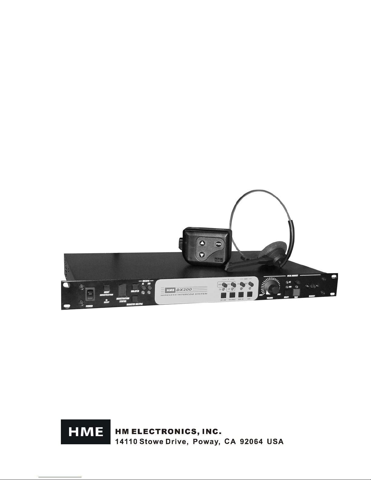
DX200
Wireless Intercom
HME# 400G527
Rev D 6/23/05
Operating Instructions
Page 2

Table of Contents
SECTION 1.
EQUIPMENT IDENTIFICATION...............................................................................................................2
MAIN EQUIPMENT FEATURES...............................................................................................................3
Base Station Features...............................................................................................................................3
Beltpac Features.......................................................................................................................................4
SECTION 2. EQUIPMENT SETUP........................................................................................................5
BATTERY CHARGER SETUP...................................................................................................................5
Connect AC Power Supply.......................................................................................................................5
Charge Batteries.......................................................................................................................................5
BASE STATION SETUP............................................................................................................................6
Equipment Connections...........................................................................................................................6
BELTPAC SETUP AND REGISTRATION.................................................................................................7
Set Up Beltpacs........................................................................................................................................ 7
Register Beltpacs.....................................................................................................................................7
INTERCOM AND AUXILIARY EQUIPMENT SET UPS ...........................................................................9
2-Wire Intercom.......................................................................................................................................9
4-Wire Intercom.......................................................................................................................................9
Auxiliary Equipment..............................................................................................................................10
8-Ohm Speaker......................................................................................................................................10
Multiple DX200 Units............................................................................................................................10
SECTION 3. EQUIPMENT OPERATION...........................................................................................11
BASE STATION OPERATION ................................................................................................................11
Front Panel Controls, Indic ators and Conne ctor......................................................................................11
BELTPAC OPERATION ..........................................................................................................................13
Beltpac Controls and Indicator Lights.....................................................................................................13
Microphone Gain Adjustment................................................................................................................14
Batteries ................................................................................................................................................14
SECTION 4. TROUBLESHOOTING....................................................................................................15
SECTION 5. TECHNICAL DATA........................................................................................................16
EQUIPMENT SPECIFICATIONS.............................................................................................................16
Base Station ........................................................................................................................................... 16
Beltpac.................................................................................................................................................. 17
BLOCK DIAGRAM..................................................................................................................................18
DX200 Base Station............................................................................................................................... 18
INTRODUCTION...............................................................................................................1
Illustrations in this pub lic ation are app roximate repre se ntations o f the ac tu al
equipment, and m ay not be exactly as the equipment appear s.
HM Electronics, Inc. is not responsible for equipment malfunctions due to
erroneou s translation o f its pub lications f ro m the ir o riginal English version.
The HME logo and product names are registered trademarks of H M Electronics, Inc. All rights reserved.
© 2005 HM Electronics, Inc.
Page 3

FCC NOTICE
This device complies with Part 15 of the FCC rules. Operation is subject to the following two conditions:
(1) This device may not cause harmful interference, and (2) This device must accept any interference
received, including interference that may cause undesired operation.
NOTE: This equipment has been tested and found to comply with the limits for a Class A digital device,
pursuant to Part 15 of the FCC rules. These limits are designed to provide reasonable protection against
harmful interference when the equipment is operated in a commercial environment. This equipment generates,
uses and can radiate radio frequency energy and, if not installed and used in accordance with the instruction
manual, may cause harmful interference to radio communication. Operation of this equipment in a residential
area is likely to cause harmful interference, in which case the user will be required to correct the interference
at his own expense.
Changes or modifications not expressly approved by HM Electronics, Inc. could void the users auth orit y
to operate this equipment.
MANDATORY SAFETY INSTRUCTIONS
FOR INSTALLERS AND USERS
Use only manufacturer or dealer supplied antennas.
The Federal Communications Commission has adopted a safety standard for human exposure to RF (Radio
Frequency) energy, which is below the OSHA (Occupational Safety and Health Act) limits.
The term “IC:” before the certification/registration number only signifies that the Industry Canada technical
specifications were met.
Base Station Antenna minimum safe distance: 7.9 inches (20 cm) at 100% duty cycle.
Base Station Antenna gain: This device has been designed to operate with an antenna having a maximum
gain of up to 7dBi.
Antenna mounting: The antenna(s) used for the base transmitter must be installed to provide a separation
distance of at least 7.9 inches (20 cm) from all persons and must not be co-located or operating in conjunction
with any other antenna or transmitter.
Antenna substitution: Do not substitute any antenna for the one supplied by the manufacturer or radio dealer.
You may be exposing person or persons to excess radio frequency radiation. You may contact your radio
dealer or the manufacturer for further instructions.
WARNING: Maintain a separation distance from the base station transmit antenna to a person(s) of at least
7.9 inches (20 cm) at 100% duty cycle.
You, as the qualified end-user of this radio device must control the exposure conditions of bystanders to ensure
the minimum separation distance (above) is maintained between the antenna and nearby persons for satisfying
RF exposure compliance. The operation of this transmitter must satisfy the requirements of
Occupational/Controlled Exposure Environment, for work-related use. Transmit only when person(s) are at
least the minimum distance from the properly installed, externally mounted antenna.
Hereby, HM Electronics, Inc. declares that the DX200 is in compliance with the essential requirements and other
relevant provisions of R&TTE Directive 1999/5/EC.
This product operates in the 2400 to 2483.5 MHz frequency range. The use of this frequency range is not yet
harmonized between all countries. Some countries may restrict the use of a portion of this band or impose other
restriction re lating to po wer le v e l o r use. Yo u should c o ntact your Spe ctr um autho rity to dete rmine po ssible re strictio ns.
Page 4
SECTION 1. INTRODUCTION
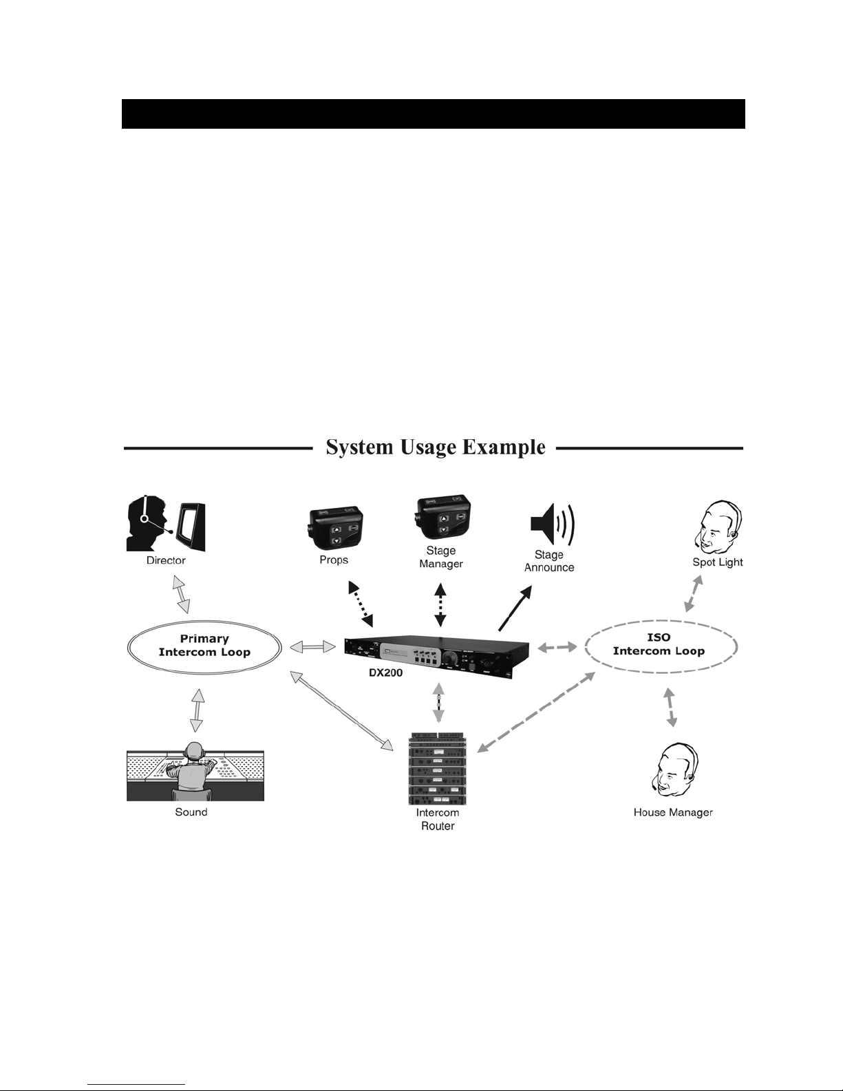
The DX200 provides private, secure communication. E a ch base station can have up to fifteen Beltpacs
“registered” to it. Four of the fifteen Beltpacs can transmit at the same time. However, by connecting two or
more base stations together, these numbers can be increased. For example, two base stations can support thirty
Beltpacs, of which eig ht can transmit at the same time. Beltpacs c an b e use d either in the push-to- talk or handsfree mode. The base station operator can stop any Beltpac from transmitting.
®
The DX200 can be used w ith RTS
and 4-wire cabled intercoms can be operated at the same time. Also, using the AUX In and AUX Out
conn ections , a secon d 4-wir e int ercom ch annel can be used.
Either a monitor speaker or a local headset can be used with the DX200. Using a local headset, the base station
operator can talk to crew members on the cabled intercom channel, Beltpacs only or all channels.
The ba s e s tati on can be opera ted usi ng st andard DC electricity or a veh icle elect rica l system for mobile
operation. A power supply and cable are included with the base station.
and Clear-Com® cabled intercom s yste ms. On the interco m channel, 2-wire
1
Page 5
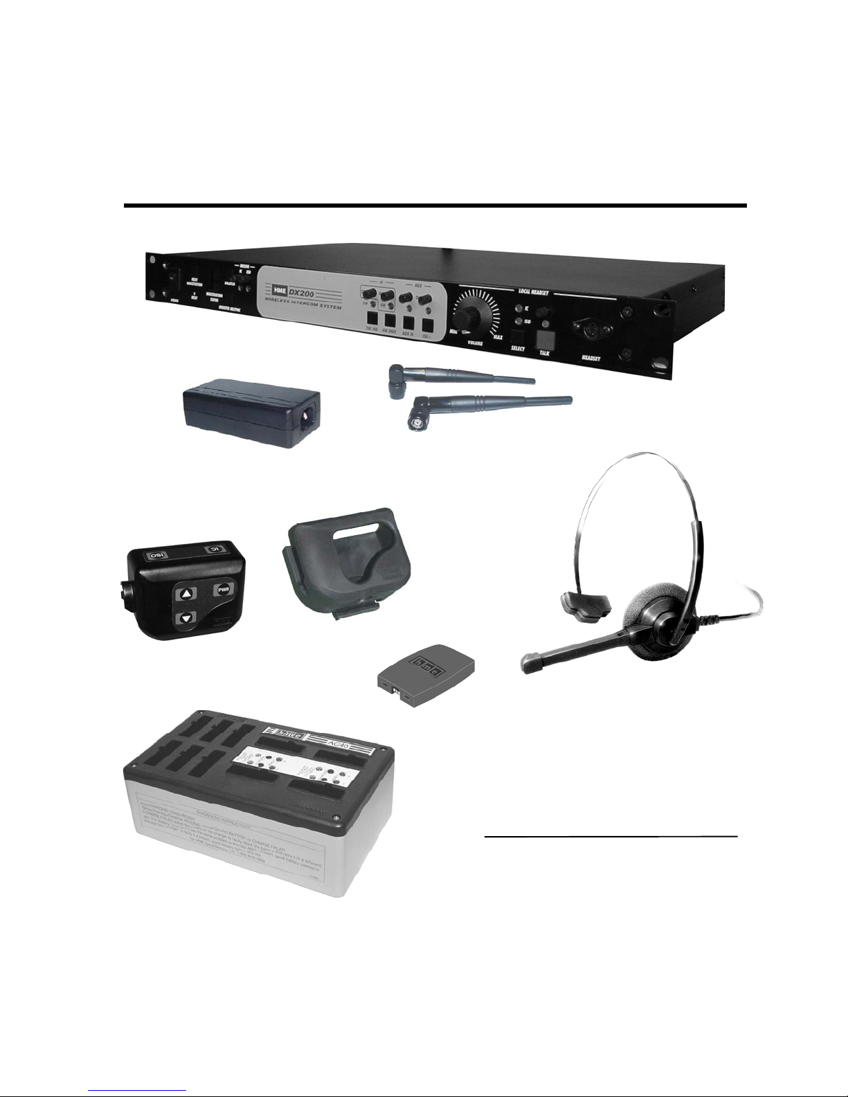
EQUIPMENT IDENTIFICATION
The following equipment i s standard with the DX200 Wireless Intercom System.
As you unpack the equipmen t, ch eck the p acking li st to be sure you received a ll items listed.
BS200 Base Station
Base Station Antennas
(1 per AC40A Battery Charger, with Power Cables)
AC40A Battery Charger
115/230 Volt AC Power Supply
(1 per Base Station, with Power Cables)
Beltpac Pouch
BP200 Beltpac
Beltpac Battery
(2 per Base Station)
OPTIONAL EQUIPMENT
HS4-3
Sin g le Earpiece & Lapel Microphone
HS14
Single-Muff Medium-Weight Headset
HS20-3
XLR Headset Adapters:
MD-XLR4M
MD-XLR4F
HS12 Hea dset
Dual - Ear p iece Lightweight Head s et
Mini-DIN to 4-Pin Male
Mini-DIN to 4-Pin Female
MD-XLR5F
2
Mini-DIN to 5-Pin Female
Page 6
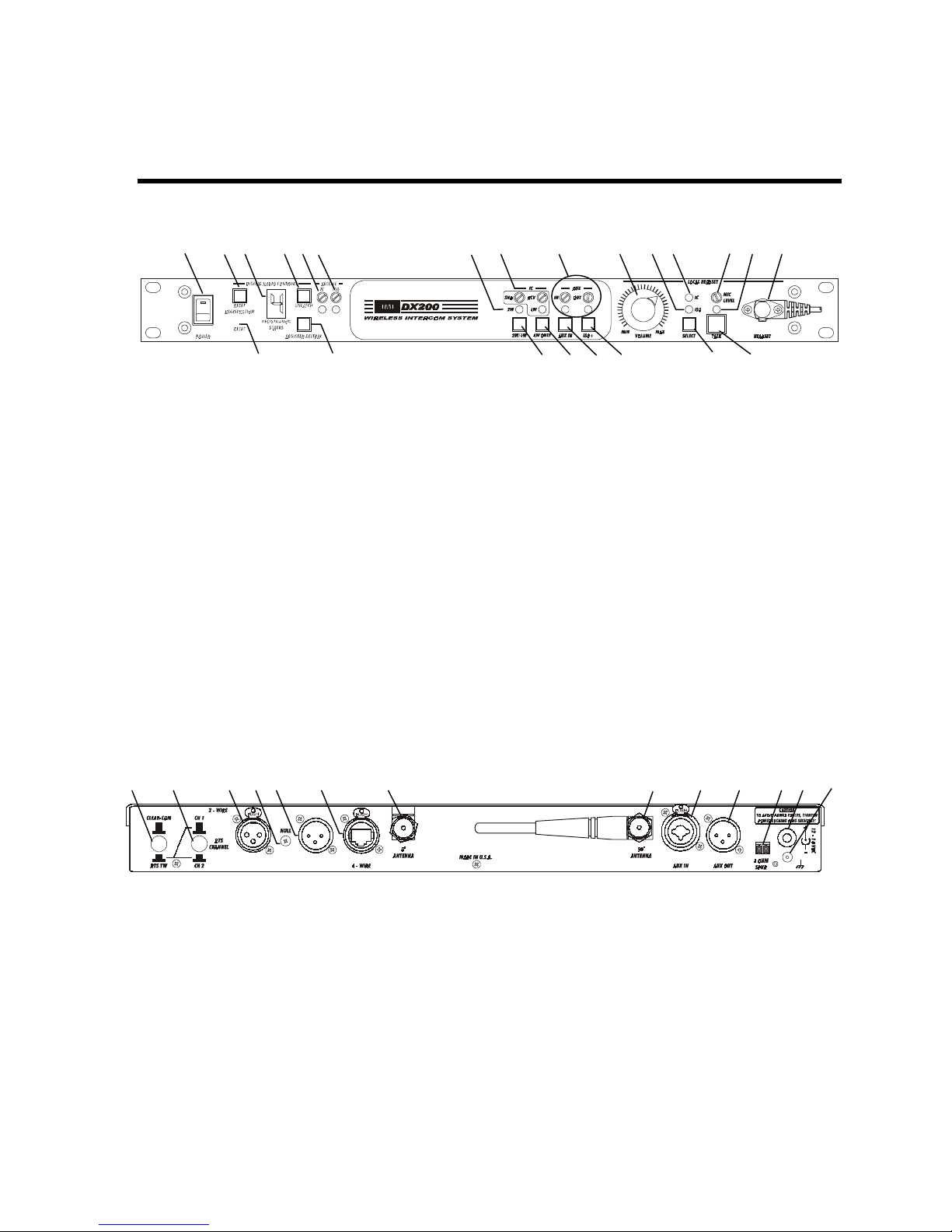
MAIN EQUIPMENT FEATURES
Base Station Features
1 2 3 4 5 6 7 8 9 10 11 12 13 14 15
1. POWER switch
2. RESET REGISTRAT ION button
3. REGISTRATION STATUS display
4. UNLATC H switch
5. IC (Intercom) receiver level control and
indicator light
6. ISO (Isolate) recei ver level contr ol and
indicator light
7. 2W and 4W indicator li ghts
8. SND and RCV (S end and Receive) controls
9. AUX IN and OUT (Auxiliary In and Out)
controls
10. LOCAL HEADSET VOLUME control
16 17 18 19 20 21 22 23
Front Panel
11. LOCAL HEADSET ISO indicator light
12. LOCAL HEADSET IC indicator light
13. LOCAL HEADSET MIC LEVEL con trol
14. LOCAL HEADSET TALK indicator light
15. LOCAL HEADSET cabl e connector
16. RESET button (recessed)
17. REGI S TER BELTP A C but ton
18. 2W/4W button
19. 4W ONLY button
20. AUX IN button
21. ISO+ button
22. LOCAL HEADSET IC / ISO SELE CT button
23. LOCAL HEADSET TA LK bu tton
24 25 26 27 28 29 30 31 32 33 34 35 36
24. CLEAR-COM / RTS TW button
25. RTS CHANNEL select button
26. 2-Wire inter com connector (fem ale)
27. NULL control
28. 2-Wire inter com connector (male)
29. 4-Wire connector
o
30. 0
ANTENNA conn ector
Rear Panel
31. 90
32. AUX IN connector
33. AUX OUT connector
34. 8-OHM SPKR 2-pin Phoenix connector
35. Power connector
36. Chassi s g round connector
3
o
ANTENNA conn ector
Page 7

Beltpac Features
1
1. Headset cable connector
2. Beltpac power lights
3. ISO (Isolate) button
4. IC (Intercom) button
5. PWR (Power) button
2 3 4 2
8 9
5
6
7
6. Volume-up button
7. Volume-down button
8. Battery
9. Battery release latch
4
Page 8

SECTION 2. EQUIPMENT SETUP
y
BATTERY CHARGER SETUP
IMPORTANT! – Before installing the system, connect the AC power supply to the battery charger and plug
it into an electrical outlet. Charge all the Beltpac batteries while the other equipment is being installed.
Charging time is about 2.5 hours.
Connect AC Power Supply
• Attach the AC power supply cable connector to the screw connector on the battery charger.
• Plug the power cable connector into the AC power supply.
• Plug the power cable i nto an elect rica l outlet.
The red lights on the charger will come on and go off, and then the yellow lights will come on and stay on.
Power supply
cable con nector
Power cable
connector
To electrica l
outlet
charger
Batter
AC power supply
Charge Batteries
Up to four batteries can be charged in the battery
charger at the same time. The battery status lights
next to each chargin g port a re explained below.
Up to six fully charged batteries can be stored in the
battery stor age ports.
• Insert a battery in each of four charging ports
until it clicks in place.
• A yellow light next to each charging port stays on
while the port is empty. When a battery is in a
charging port, a flashing yellow light next to it
indi ca t es CHARGE PENDING, which m ea ns th e
battery is too hot. Adjust the room temperature or
move the charger to a cooler area. When a battery is
in a charging port, a ye llo w light o n ste ady ne xt to it
means CHARGE FAILED. If this happens, follow
the instructions on the side of battery charger.
• A red CHARGING light next t o a battery port
stays on while a battery in the port is charging.
A green READY light next t o a bat tery port goes
on when a battery in the port is fully charged.
Store fully charged batteries in storage ports.
Batteries should not b e left in c harge ports afte r b eing
fully charged. If a battery is left in a charge port for
more than three weeks, the yellow indicator may light
up. In this case, it does not indicate a faulty battery.
Charged batteries
in storage port s
Empty
charging ports
Battery in
chargin g port
5
Page 9

BASE STATION SETUP
The following description is for a basic, stand-alone DX200 system setup. Connections with 2-wire and 4-wire
intercoms, and other auxiliary equipment are described in the INTERCOM AND AUXILIARY EQUIPMENT
SETUPS on pages 9 and 10.
Equipment Connectio ns
1 2 3 4
The num bers (#
Step 1. Connect the two enclosed antennas to the antenna connectors (#1 and #2) on the rear panel of the b ase
station. Position the antenna at the 0° ANTENNA connector (#1) ve rtically. Position the antenna at the 90°
ANTENNA connector (#2) horizontally, p ointing to the left as indicate d on the panel. Turn the sleeve on
each of the antenna connectors clockwise to tighten them securely in place.
Step 2. Plug the connector at the end of the AC powe r supply cord into the 12-14VDC power connector (#3) on the
rear panel of the base station. Turn the nut on the c able connecto r c lockwise to secure it to the bas e station.
Plug the large female connector at one end of the AC power cord into the power supply . Plug the other end
of the AC power cord into an elec tric al outlet.
Step 3. Co nnect a grounding wire from # 4 to an earth ground.
Step 4. Plug a heads et into the HEADSET co nnector (#8) on the front panel of the base s tation.
6 7
) below refer to items on the illustrations above.
Rear Panel
Front Panel
8 5
Step 5. Press the POWER sw itch (#5) to tu rn on the base s tation. The red light on the s witch shou ld go on.
6
Page 10

BELTPAC SETUP AND REGISTRATION
The first time you operate the DX200 system, you must register each Beltpac for use with a specific base
station. The base station will then recognize all registered Beltpacs when their power is on, and will know the
diff erence betw een them and other electronic equipment operating on the same frequencies. If a Beltpac is added
or replaced later, the new one must be registered and the old one remains in memory. A maximum of 15
Beltpacs can be registered to a single base station at one time.
Set Up Beltpacs
Before registering them, set up all Beltpacs as follows.
Step 1. Insert a fully charged battery in the
Be ltp ac, with the metal contacts on
the end of the battery inse rte d first.
Press it in until it snaps.
Step 2. Place the Beltpac in the pouch.
Step 3. Plug the headset cable connector into the Beltpac.
Step 1
Step 2
Step 3
Register Beltpacs
Beltpacs must be within 6 feet (1.83 meters) of the base station while you are registering them. Be certain the
base station powe r is o n, and each Beltpac yo u are g oing to regis ter is turned of f be fore you begin. Beltpacs that
are alr eady regi s tered can be on or off.
Step 1. Put the heads et, of the Beltpac being regis tered, on your head .
Step 2. Press the REGISTER BELTPAC button on the f ront panel of the base s tation (#7 on base station front
panel illustration).
• The REGISTRATION STATUS display (#6 on base station front panel illustration) will show a
smal l “o” for open.
NOTE: If you wait too long before going on to Step 3, the base station will go out of the registration
mode and you will have to repeat Step 2.
Step 3. Press and ho ld the ISO button on the Beltpac while you p ress and
release the PWR ( power) butto n to tu rn the unit o n, then rele as e the
ISO button. This will caus e the Be ltp ac to enter the re gistration mode .
• The two power lights at the corners of the Beltpac near the IC
and ISO buttons will begin blinking red, then will blink green
two or three times and go off.
•
Wait! There may be a short delay.
If registrati o n is successfully complete d :
• A voice message in the headset will say “Power on, Beltpac #, Version #, Begin registration, Registration
complete, …”
• After a delay o f up to 15 se co nds, the REGISTRATION STATUS display w ill sho w the ID numbe r assig ned
to this Beltpac for about 10 seconds.
NOTE: ID numbers are assign ed sequentiall y as 0 thr u 9, A, b, C, d a nd E.
• The power light on the Beltpac, next to the IC button, will remain on steady green.
• Repeat Steps 1 to 3 above for each Beltpac to be registered.
7
Page 11

If registration fai led :
• A voice message in the headset will say “Power on, Beltpac #, Version #, Begin registration, …” Both
power lights on the Beltpac will be blinking red, and there may be a delay of up to 90 seconds before you
hear “Registration failed.”
• Press th e RESET button on the base station. To press the RESET button, insert a small paper clip or
similar object into the RESET hole at the lower-left corner of the base station front panel. When the
REGISTRATION STATUS displa y becomes blank, press the REGISTER BELTPAC button and register
the Beltpac again. If registration fails again, call your dealer for assistance.
If you try to register more than 15 Beltpacs
• An F will appear on the REGISTRATION STATUS display on the
base station and you will hear “Registration failed” in the headset.
• Clear all current registrations by pressing the RESET
REGISTRATION button and the RESET button at the same time.
To press the RESET button, insert a small paper clip or similar
object into the RESET hole at the lower-left corner of the base
station front panel. Continue holding the RESET REGISTRATION button after you release the RESET
button, until the clear code “c” (lower case) appears on the REGISTRATION STATUS display.
• Register all active Beltpacs, one at a time. Previously registered Beltpacs must be re-registered.
:
NOTICE
You have completed the stand-alone system setup.
The instru ct i on s u nder INT ERCOM AND AUXILIARY EQUIPMENT SETUPS on th e followin g p a g es
are for setting up additional equipment which you may want to use with your DX200, such as a 2-wire
intercom, 4-wire intercom, an external speaker or other auxiliary audio equipment. Instructions are also
provided for daisy-chaining two or more base stations together.
8
Page 12

INTERCOM AND AUXILIARY EQUIPMENT SETUPS
1 2 3 4 5 6 7 8 9
Rear Panel
10 11 12 13 14 15 16 17 18 19 20 21 22
Front Panel
The num bers (#
23 24 25 26 27 28 29 30
) below refer to items on the illustrations above.
2-Wire Intercom
Step 1. If us ing a 2- wire interco m, p lu g it into the base s tation at #3 or #5, depending on whether a male or female
connec tion is required.
Step 2. Depe nding on whether you are u s ing a C lear-Com® o r RTS® compatible 2 -wire intercom system, position
the CLEAR-COM / RTS TW button (#1) as follow s:
In position = RTS® Mode Out po s ition = Clear-Co m® Mode
Step 3. If you selected RTS TW, pos ition the RTS CHANNEL selec t button (# 2) to the desired channel as follo ws:
Out position = Channel 1 In position = Channel 2
Step 4. Press the 2W/4W b u tton (#25) on the front panel of the bas e station. The 2W and 4W lights (#15) above the
butto n s ho u ld g o on. Turn the Be ltp ac power on. Pre s s the IC button on the Beltpac pres s ed and speak into
the headse t microphone. Y ou will he ar a de laye d echo of your v oice. A d just the NULL control (#4) with a
small scre wdrive r while you are speaking, until the echo is eliminated.
4-Wire Intercom
Step 1. If us ing only a 4-wire intercom, plug it into the 4-WIRE connector (#6).
Step 2. Press the 4W ONLY b utton (#26). The 4W light (#15) above the button should go on.
Step 3. Adjus t the 4 - wire intercom send and receive levels with the SND and RCV controls (#16).
Pin designations for the RJ45
4-WIRE connector are as follows: Pins 1, 2, 7 & 8 = N/C
Pin 3 = Interco m O u t +
Pin 4 = Intercom In +
Pin 5 = Intercom In –
Pin 6 = Interco m O u t –
NOTE: If no 2-wire intercom will be used, you must
heard in the headsets .
press the 4W ONLY bu tton (#26), or a squ eal will be
9
Page 13

The num bers (#
) below refer to items on the illustrations on page 9.
Auxiliary Equipment
Step 1. If using auxiliary equipment, such as another intercom, a CD player or other audio source, connect its
output cable connect or (ma le) to t he AUX IN connect or (#7) , an d its i nput cable connector (female) to
the AUX OUT con nector (#8) (if applicable).
The cable connectors must be 3-pin
XLR type fo r balanced +20dBV Pin 1 = Ground
maximum audio input/output, with Pin 2 = Audio +
the fo l l owing p i n co nnect i ons: Pin 3 = Audio –
Step 2. If the aux iliary equip ment provides audio input only, pre s s the AUX IN button (#27). The light above the
butto n (#17) s hould go on. Liste n to the audio inpu t in your head s et as you adj u st the IN control (#17)
above the light to the desired level.
Step 3. If the aux iliary equip ment requires two-way communication, have so meone lis tening at the auxiliary unit.
Press the ISO+ button (#28) on the front panel of the base station. The light above the button should go on.
While speaking into your headset micropho ne , ad just the OUT control (#17) above the light to the desired
listening level at the auxiliary unit. Liste n to the audio input in you r heads et as you adj u st the IN control
(#17) above the light to the desired level.
8-Ohm Speaker
Step 1. If an external 8 ohm speaker will b e used, connect its cable wires to the 8 OHM SPKR 2-pin Phoenix
connector (#9).
Step 2. Adjust the speaker volume with the LOCAL HEADSET VOLUME control knob (#18).
NOTE: Either a local heads et or an external speaker can b e used, but not b oth. The LOCAL HEADSET
VOLUME control k no b is the adj u s tment for b oth.
Multiple DX200 Units
Two or more DX200 units can be “daisy-chained” together with cables connected to the 2-wire connectors
(#3 and #5) on the rear panels of each base station, following Clear-Com
NOTE: DX200 does not provide or require 2-wire lin e power.
The cable connectors must be
3-pin XLR type for balanced RTS
+20dBV maximum audio Pin 1 = Common Pin 1 = Common
input/output, with the Pin 2 = Channel 1 Pin 2 = N/C
following pin connections: Pin 3 = Channel 2 Pin 3 = Audio
If “daisy-chaining” multiple base stations, you must do the following:
Step 1. Remove the cover from one
locate the JP1 jumper on the main ci rcu it board.
Slide the jumper to the up ward pos ition
and replace the cover on the base station.
Be s u re yo u do this in only one
of the base s t ations and
base station.
®
Mode Clear-Com® Mode
®
/RTS
®
stand a rds.
+
JP1
Jumper
Step 2. For each base s t ation, follow all the s teps for
the base station setup on page 6.
10
Page 14

SECTION 3. EQUIPMENT OPERATION
BASE STATION OPERATION
Front Panel Controls, Indicators and Connector
1. POWER Switch
2. Beltpac Registration Controls a nd Sta t us Indica t or
3. UNLATCH Button
4. IC (Intercom) and ISO (Isolate) Receiver Indicators and Controls
5. Local Headset Connector, Indicators and Controls
1 3 4
2 6 7 5
Press the upper part of the switch to turn the power on. A red light on the switch will be lit when the base
station power is on. Press the lower part of the switch to turn the power off. The red light will go off. All
settings are preserved when the power is turned off, and will be restored when the power is turned on again.
Use these controls to regist er each Beltp ac used with a specific bas e station, as descr ibed on pages 9 a nd 10 .
Use this butto n to unlatch all Be ltpac transmitters. (B e ltpac us ers c an “latc h” their Be ltpac s o n, in order to talk
and listen to e ach o ther. Bas e s tatio n ope rators c an use the UNLATCH butto n to s top B eltpac c o nve rsations , i n
order to have uninterrupted communication with the Beltpac users.)
Ligh ts indica te whether Beltpa c reception is IC or ISO. Use IC and ISO controls to independently adjust
IC and ISO recei ve l evel s . NOTE: This adjustment does not affect Beltpac-to-Beltpac communication.
• Adju s t the m icr ophone l e vel control, above t he TALK button on the front panel, to mid-point. The
level can be readjust ed during use, as needed.
• Adjust the receive level by turn ing on a Beltpac, s p eaking into the Beltp ac headset m icrophone and
listening through the local headset earpiece while adjusting the VOLUME control on the b as e s tatio n to
the desired level.
• Use the SELECT button to select communication via IC or ISO. Above the SELECT button, the
indicator light will be lit f o r the se lec tio n y o u made . IC w ill allo w you to co mmunic ate v ia the inte rco m
channel. ISO will send your audio to Be ltp acs and auxiliary output if ISO+ is enabled (See #7 above).
NOTE: If neither 2W nor 4W is on, this will have no effect. It will stay on ISO.
• For open communica tion , pres s and relea s e the TALK button qui ckly to “latch on .” T o “l atch off,”
press and release the button again quickly.
• For momentary communication, press and hold the TALK button for more than one second. In this
mode, the selected channel will remain open only as long as you are pressing the TALK button.
The TALK light indicates the TALK mode is active via the local headset.
• Use the TALK control knob to adjust the outbound audio level from the local headset microphone.
• Use the VOLUME contr ol knob to a d ju s t th e input to t he local hea d s et ear p iece.
The following base station indicators and controls are used only if 2-wire or 4-wire
intercoms, or other auxiliary equipment is being used with the DX200, as described under
INTERCOM AND AUXI L IARY E Q UI PMENT SE T UPS on pages 9 and 10.
11
Page 15

6. 2Wire/4Wire IC Indicators and Controls
The 2W/4W button turns on/off both 2-wire a nd 4-wire i nte rcom s sim ult an eously. Th e 2W light a bove th e
button indicates intercom on/off status. The 4W ONLY button turns on/off the 4-wire intercom alone. The
4W lig ht above the button indicates i nte rcom on/ off s tatus. Use the SND an d RCV controls in the outlined
area to ad ju s t th e 4 - wi re inter com send and receive levels.
7. AUX IN and ISO+ Indi c a t ors a nd Contr ols
The AUX IN button enables/disables the auxiliary input. The light above the button indicates auxiliary
equipment’s on/off status. IN and OUT controls adjust auxiliary inbound and outbound audio levels.
ISO+ button enables/disables the AUX IN / OUT audi o input and out put. The l ight above the button
indicates ISO+ on/off status. Either AUX IN or ISO+ can be on, but not both at the same time. If ISO+
is on and you push the AUX IN button, ISO+ w ill automatically go off when AUX IN goes on, and vice versa.
Enabling ISO+ will open an audio path from the Beltpacs and local headset to AUX OUT.
12
Page 16

BELTPAC OPERATION
Beltpac Controls and Indicator Lights
The Beltpac control buttons have a snap action. They will activate when
pressed firmly. Use your fingertips, not your fingernails, to press the buttons.
Power On/Off
• Power On – Press an d relea s e the PWR (power) button.
A voice messa ge in the ea rpiece will say “power on,” and the red power lights
at t he corners of the IC and ISO buttons will go on. After a short time, one light
will go off and the other will change to green, indicating the Beltpac is ready for use.
The REGISTRATION STATUS indicator on the base station will mo mentarily indicate the I D of the Beltpac.
• Power Off – Press and hold the PWR button for approximately two seconds.
A voice messa ge in the ea rpiece will say “power off,” and the green power light will go off.
NOTE: While the Beltpac is transmitting, the green power light will be flashing.
The green power light will be on steady whenever the Beltpac is ready, but not transmitting.
ISO (Isolate) an d IC (Intercom)
Use the ISO button to communicate with other Beltpac users and the DX200 base station operator.
Pressing ISO on the Beltpac will send audio to AUX OUT if ISO+ button on the base station is on.
Use the IC button to communicate via the intercom chan nel and with th e DX200 base station operator, or
anyone listening to a local speaker connected to the DX200 base station. Pressing IC on the Beltpac will send
audio to the intercom if intercom is on.
• Push-To-Talk Mode Setting – To se t the B e ltpac fo r pus h-to- talk (P TT) co mmu nicatio n, with the po w e r
off , press and hold the volume-dow n T and ISO butto ns w hile y o u p ress and releas e the PWR (pow e r) button.
You will hear “Hands-free off” in the headset earpiece. Pres s and hold t he IC or ISO button while talking.
• Hands-free Mode Setting – To set the Beltpac for hands-free communication, with the power off,
press and hold the volume-up S and ISO buttons while you p ress and release the PWR (powe r) butto n. You
will hear “Hands-free on” in your headset earpiece. When set up for ha nds- free commu nica tion, th e Beltpa c
can be operat ed in ei ther hands - free or PTT.
NOTE: The a bove s e ttin gs are saved in memory and only need to be repeated when you want to change between
hands-free and PTT operation. When changing mode s , if bo t h power lights begin b linking, turn the B eltpac
off and beg in again.
Hands-f ree and Pus h-To -Talk mo de se ttings af f e ct b o th IC and ISO. Individual ad ju st ment is not po ss ib le .
• Push-To-Talk Mode Operation – press and hold the IC or ISO button for more than one second. In
PTT operation, audio will be transmitted only while you are pressing the IC or ISO button.
• Hands-free Mode Operation – Quickly press and release the IC or ISO button to “latch” the
transmitter on. Talk and listen, as in a normal telephone conversation. Press and release the IC or ISO
button aga in t o “u nla tch, ” to end th e conversa tion. All Beltpacs can be unlatched by the base station operator,
by pressing the UNLATCH button on the base station.
NOTE: In hands-free mode, pressing the IC button while latched in ISO will latch on IC. Pressing the ISO
button while latched in IC will latch on ISO.
Volume Up/Down
• Volume Up Adjustment – Each time you press and release the volume-up S button, a beep will be
heard in the earpiece as the volume increases one step. If you press and hold the volume-up button, repeating
beeps will be heard as the volume steps up to maximum. When maximum volume is reached, “maximum”
will be heard in the earpiece, and will be repeated until you release the volume-up button.
• Volume Down Adjustment – Each time you press and release the volume-down T button, a beep will
be heard in the ear piece as the volu me decreases one s t ep. If you pr es s and hold t he volum e- down butt on,
repeating beeps will be heard as the volume steps down to minimum. When minimum volume is reached,
rapidly repeating beeps will be heard.
13
Page 17

Microphone Gain Adjustment
Some users talk louder or softer than others. To allow for this, microphone gain adjustment is provided.
To increase microphone gain – Press the volume-up S button while holding down the ISO button in
the normal operating mode. The microphone gain increas e can be monitored through sid etone, o r pre ferably by
someone else on a Beltpac or at the base station.
To Decrease microphone gain – Press the volu m e-down T button while holding down the ISO button
in the normal operating mo d e. The micropho ne g ain de crease can be mo nitored through side tone, or preferably
by someone els e on a Be ltp ac or at the base station.
NOTE: You will hear “Maximum” if you attempt to go higher than maximum microphone gain.
You will hear beeps if you attempt to go lower than minimum microphone gain.
Microphone gain will be saved in non-volatile memory and does not require readjustment each time
the power is turned on.
Batteries
Battery
Battery
release latch
Change Batteries
When a bat tery becomes weak, a voice in th e
earpiece will say “Change battery.” When this
happens, take the Beltpac out of its pouch and
remove its battery. Slide the arrow-shaped batteryrelease latch in the direction of the arrow. Pull up
on the end of the battery near the battery-release
latch and lift the battery out of the Beltpac, or turn
the Beltp ac over and catch the batte ry in your hand.
When replacing a battery in the Beltpac, place the end
of the battery with the metal contacts into the battery
holder on the Beltpac, in the same position as the
battery you removed. Press the top of the battery
carefully into the battery holder until it snaps in place
under the battery-release latch.
14
Page 18

SECTION 4. TROUBLESHOOTING
If you are unable to correct any of the problems described below, contact your dealer for assistance.
• Red light on base station power switch does not come on.
Be certain power cords are properly connected to base station, power supply and electrical outlet.
• Beltpac power lights do not turn green and “out of range” is heard in the headset.
Be certain your base station power is on. Turn the Beltpac and base station power on and off.
You may be too far from the base station. The range varies with each location’s layout.
• When trying to register, it keeps saying registration failed.
Refer to “If registration failed” on page 8, an d repeat the registrat ion procedure.
• Others cannot hear me when I talk.
Be certain the headset is securely connected to the Beltpac or base station, and that you are pressing the IC
or ISO button on the Beltpac, o r the TALK butto n on the base station. Be certain the appropriate IC or ISO
setting is selected under LOCAL HEADSET on the base station.
• People on the 4-wire intercom cannot hear me or I cannot hear them.
Be certa in t he cabl es are secu rely connected and the 4 - wire intercom is on. If us ing a local heads et, be
certain the IC setting is selected under LOCAL HEADSET on the base station.
• People on the RTS/ClearCom systems cannot hear me or I cannot hear them.
Be certa in t he cabl es are secu rely connected and the 2 - wire intercom is on. If us ing a local heads et, be
certain the IC setting is selected under LOCAL HEADSET on the base station.
• The 2-wire intercom is on and there is a loud squeal whenever I try to talk.
This can occur if two or more base stations are daisy-chained and the JP1 jumper on the circuit board in
one of the base stations has not been set properly. Contact your dealer.
• Settings are not retained when the base station power is turned off and on again.
The internal battery may be low. Contact your dealer.
2400MHz cordless telephone interference —
If there is a 2400MHz cordless telephone nearby, interference may occur. However, because the DX200
is a frequency-hopping system, this problem is unlikely. If it does occur, changing frequencies on the
telepho ne may allev iate the prob le m. If not, mo v e the pho ne as f ar as prac tical f ro m the b ase statio n, o r use
another type phone.
In the event of an electrical power outage —
such as from a lightning storm or power generator failure, if you experience problems with your HME
equipment after the electricity comes on again, unplug the AC power supplies from their electrical outlets
and wait 15 seconds, then plug th em back in.
15
Page 19

SECTION 5. TECHNICAL DATA
EQUIPMENT SPECIFICATIONS
Base Station
GENERAL ⎯
Frequency Range: 2400 – 2483.5 MHz
Frequency Response: 200 Hz to 3.5 kHz
Power Requirements: 100-240VAC, 50-60Hz or 12-14VDC
Temperature Range: 32-122°F (0-50°C)
Size: 19” x 1.72” x 17.13” (1-RU) (48.26 x 4.37 x 43.51 cm)
Weight: 9.2 lbs. (4.18 kg) maximum
# of Beltpacs per Base: 15 can be registered
Any 4 can have simultaneous full-duplex communication at one time
4-Wire I/O: RJ45, 600Ω balanced, level adjustable, simultaneous operation with 2-wire
2-Wire I/O: XLR-3M, XLR-3F, externally-switchable RTS
200Ω, level adjustable, null adjustable
Auxiliary Input: XLR-3F/¼” (6.35 mm) combo jack, 600Ω balanced, level adjustable
Auxiliary Output: XLR-3M, 600Ω balanced, level adjustable
8Ω Speaker Output: 1W into 8Ω
Headset Connector: 4-pin mini-DIN
Electret microphone
Headset Output: 250mW into 32Ω
Front Panel Controls: Power switch
Reset Registration, Reset, Unlatch and Register Beltpac buttons,
IC and ISO Recei ve l evel adjust ments, IC 2 W/4W and 4W-O nly butt ons,
IC4W-O nly Send and Recei ve l evel adjus tmen ts,
Auxiliary In and ISO+ buttons, Auxiliary In and Out level adjustments,
Rotary knob for volum e adju s tment ,
Headset IC/ISO Select button and Headset Talk button
Fron t Panel Indicators : Registrat ion St atus indicator, IC and I S O Recei ve LEDs,
IC 2W and 4W-Only LEDs, Auxiliary In/Out LEDs,
Headset IC/ISO select LEDs, Headset PTT LED
Rear Panel Controls: Clear-Com
2-wire channel line null adjustment
Antenna Type: External ½ -wave dipole (R-TNC connector)
RX/TX horizontal/vertical diversity
System Distorti on : < 2 %
Communication Security: 64-bit encryption dual-slot diversity
®
/RTS® mode switch, RTS® Channel 1/2 switch,
®
or Clear-Com
®
mode,
TRANSMITTER ⎯
Type: Frequency hopping, spread spectrum
Transmit Power: 100mW burst
Modulation Type: Gaussian filtered FSK, TDM
Frequency Stability: 13 ppm
Harm onics/ Spurious: Exceeds FC C and ETSI s p ecificat ions over temperatu re
RECEIVER ⎯
Type: Frequency hopping, spread spectrum
RF Sensitivity: <−90dBm w 10
Frequency Stability: 13 ppm
Distortion: <2%
16
-3
BER
Page 20

Beltpac
GENERAL ⎯
Frequency Range: 2400 MHz – 2483.5 MHz
Antenna Type: Internal, horizontal/vertical diversity
Frequency Response: 200 Hz to 3.5 kHz
Battery Requirements: 3.6V lithium ion
Battery Life: Up to 20 hours
Temperature Range: 32-122°F (0-50°C)
Weight: 7.4 oz (.21 kg) with battery and pouch
Headset Connector: 4-pin, mini-DIN
Mic Input: Electret microphone
Headset Output: 160mW into 32Ω
Controls: Power, Volume-up S, Volume-down T, IC, ISO
Indicators: Dual -color LED (red/green)
Communication Security: 64-bit encryption
System Distorti on : < 2 %
TRANSMITTER ⎯
Type: Frequency hopping, spread spectrum
Transmit Power: 100mW burst
Transmissi on Modes: Momentary or latch
Modulation Type: Gaussian filtered FSK, TDM
Frequency Stability: 13 ppm
Harm onics/ Spurious: Exceeds FC C and ETSI s p ecificat ions
RECEIVER ⎯
Type: Frequency hopping, spread spectrum
RF Sensitivity: <−90dBm w 10
Frequency Stability: 13 ppm
Distortion: <2%
-3
BER
17
Page 21

18
BLOCK DIAGRAM
DX200 Base Station
 Loading...