

Page 1

COM401
Person-to-Person COMMUNICATOR
OPERATING INSTRUCTIONS
The COM401 is a person-to-person wireless Communicator. Operation of this belt-pac unit is
simply push-to-talk and release to listen. The COM401 comes with its own battery charger.
IMPORTANT: Before using the Communicator, plug the battery charger into an AC electrical
outlet, and place all Communicator batteries into it for charging. Refer to the
battery charging instructions in section II on page 3.
I. COM401 COMMUNICATOR
A. Communicator Controls and Indicators
1 – POWER button; turns Communicator on and off.
2 – VOLUME control buttons; adjust listening level in earpiece.
®
®
3 – Power light; lights when power goes on, and remains lit until battery needs
replacing or Communicator is turned off. The power light blinks rapidly when
transmitting on “A” or “B” channel.
4 – Buttons A & B; Either button “A” or button “B” must be pushed and held to
talk, and released to listen. The two buttons are in convenient positions whether
Communicator is worn on left or right hip.
5 – Button C; switches from one transmit frequency to another, two channels higher.
The power light will blink slowly, indicating an alternate frequency is being used.
NOTE: All COM401’s must be on the same frequency in order to communicate.
6 – Battery; provides power for the wireless belt-pac Communicator.
7 – Battery release latch; slides to release battery for removal, and snaps in place
when a battery is inserted to secure battery in Communicator.
8 – 5-pin DIN receptacle; receptacle for earpiece/microphone cable connector.
Figure 1. Communicator controls, connector and indicator light
HM ELECTRONICS, INC. 6675 Mesa Ridge Rd., San Diego, CA 92121 USA !! Phone: 1-800-848-4468 Fax: (858) 552-0172
HME# 400437 k
Rev B 7/19/00
Page 2

A. Wearing the Communicator
To wear the COM401 COMMUNICATOR® on your
belt (or waist band), simply squeeze open the belt
clip on the back of the Communicator pouch and
slide it over your belt. It can be worn on your left or
right side.
Plug the headset cable plug into the receptacle on
the side of the Communicator. Refer to Figure 2 for
proper wearing of the headset. Place the headset
earpiece on your ear, and clip the microphone to
your lapel or the front of your clothing, and clip the
collar clip to your collar as shown in Figure 2.
Figure 2. Correct wearing l
of the HS4 Headset
with lapel microphone
B. Operating the Communicator
Turn the Communicator on by pressing the POWER button. Be certain the red power
light on top of the Communicator is lit, indicating it is turned on. If the power light is
not lit, or if it goes off during Communicator operation, the battery must be changed.
To operate the Communicator, simply push and hold either the “A” or “B” button on
top of the unit while talking. Speak into the microphone and listen for your own voice
in the earpiece. Adjust the volume by pushing on the up ▲ or down ▼ volume control button on the transceiver until a comfortable listening level is reached. When you
have finished talking, release the “A” or “B” button immediately.
C. Communicator Frequency Selection
If it is necessary to change the operating frequency of the COM401, refer to Figure 3
for the Communicator DIP switch location, and to the following table for DIP switch
settings.
NOTE: Switch #1 in the Communicator is
on the left side.
Switches #5-10 are not used.
Figure 3. To access the frequency selection switch
in the Communicator, remove the rubber
DIP switch cover in the battery compartment
Communicator DIP Switch
Configuration Settings
Channel
0 468.4875MHz
*
1 468.7625MHz ON
2 468.8375MHz ON
3 469.1375MHz ON ON
4 469.4625MHz ON
5 469.6375MHz ON ON
6 469.6625MHz ON ON
7 469.8875MHz ON ON ON
8 468.4875MHz ON
9 468.7625MHz ON ON
10 468.8375MHz ON ON
11 469.1375MHz ON ON ON
12 469.4625MHz ON ON
13 469.6375MHz ON ON ON
14 469.6625MHz ON ON ON
15 469.8875MHz ON ON ON ON
TX and RX
frequencies
DIP Switch
1 2 3 4
* Default
2
Page 3
II. The Optional Battery Charger
A. Battery Charger Power Supply Connections in the U.S.A.
NOTE: For use outside the United States, see 230VAC
adapter connections in section IV, B.
Connect the battery charger cable to the 16.5VAC
adapter as shown in Figure 4. Plug the adapter into an
AC electrical outlet and secure it to the outlet with the
grounding screw (if provided). The green and red lights
will come on, one at a time, until they are all lit. Then
they will go off, one at a time, indicating the charger is
ready for use when all the lights are off.
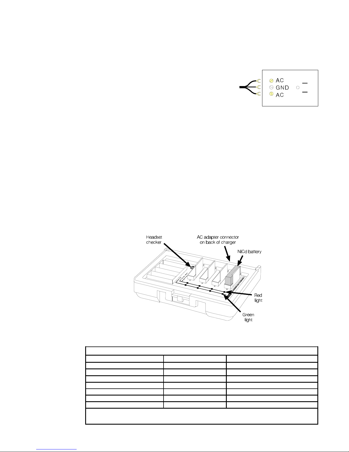
Place batteries in the AC420 Battery Charger as shown in Figure 5. A few seconds
after each battery is placed in the charger, the red CHARGING light on the panel
adjacent to the battery will indicate the battery charging status. See the CHARGING
LIGHT STATUS TABLE below for a detailed explanation of what is happening.
When the battery is fully charged, the green READY indicator below it will light
(approximately 4 hours).
Figure 4. 16.5VAC adapter
cable connections cable connections
CAUTION: Do not remove batteries from the battery charger until the green
READY light is lit, or the charger will restart the charge cycle.
Figure 5. Battery charger shown with a properly installed battery
CHARGING LIGHT STATUS TABLE – WITH BATTERY INSERTED
RED CHARGING LIGHT WHAT IT MEANS WHAT TO DO
OFF Charger doesn’t see the battery SEE NOTE
STEADY ON Battery is being charged Wait. Do not remove battery.
BLINKS: 2 seconds ON; 2 seconds OFF Battery is being discharged Wait. Do not remove battery.
BLINKS: 2 times quick; 3 seconds OFF DISCHARGE ERROR Battery is not discharging properly. SEE NOTE
BLINKS: 3 times quick; 3 seconds OFF CHARGING ERROR Battery is not charging properly. SEE NOTE
BLINKS: 4 times quick; 2 seconds OFF LOW BATTERY ERROR SEE NOTE
BLINKS: 5 times quick; 2 seconds OFF CHARGING ERROR SEE NOTE
Either the battery or the charger has a problem. Mark the battery and retry in a different slot. The battery is faulty if it
NOTE:
has the same problem in a different slot AND a known-good battery passes in the same slots. The charger circuitry is faulty if
a known-good BATTERY fails in the same slots.
3
Page 4

B. Battery Charger Power Supply Connections Outside the U.S.A.
In countries that require a 230 volt AC power supply, the power supply cable connections must be made as described below.
Step 1 Connect an electrical plug to the wires on the power cable according to color
codes (BrownBrown = live, BlueBlue = neutral, Green with yellow stripesGreen with yellow stripes = ground).
Step 2 Remove the spade lugs from the wires of the cable on the back of the battery
charger. Cut the connector off the AC adapter output cable. Strip enough of
the insulation from the wires of both cables, so they can be spliced. Splice
the wires from the AC adapter cable to the wires of the battery charger cable.
Cover the splice with electrical tape or shrink tubing.
Step 3 Plug the electrical plug into the power supply. The green and red lights will
come on, one at a time, until they are all lit. Then they will go off, one at a
time, indicating the charger is ready for use when all the lights are off.
Figure 6. 230VAC power supply wiring for battery charger
The COM401 is a wireless radio system, type-accepted under Part 74 and Part 90 of the
Federal Communications Commission (FCC) Code of Federal Regulations governing
general purpose applications. The system requires an FCC station license if operated
within the United States or its possessions. Because licensing depends on the system’s
application, it is the user’s responsibility to apply for a license from the Federal
Communications Commission.
4
 Loading...