

HM Digital PS-202 User Manual
USER’S GUIDE
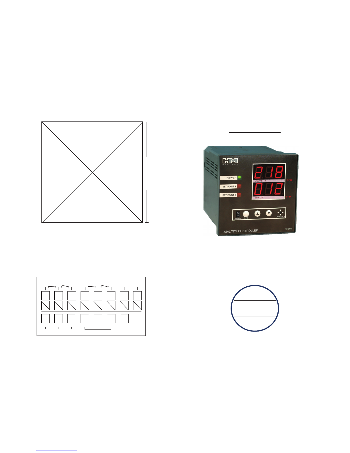
PANEL CUT-OUT DIAGRAM
M
H
D I G I T A L
®
PS-202
PANEL MOUNT DUAL DISPLAY
TDS CONTROLLER
1. Using a knife, cut the diagram out (cut on the outer part of the line).
2. Align the cut-out to your panel and draw cut marks.
3. Cut the hole in the panel to the precise dimensions of the cut-out:
3-9/16 in. x -3-9/16 in. (90 mm x 90 mm)
--> See the installation section for complete instructions.
CONTACT DIAGRAM
3 9/16 in. (90 mm)
3
9
/16 in. (90 mm)
AC
WHITEREDBLACK
LINE 1 SENSOR (IN)
110-220V
LINE 2 RELAY (SWITCH)
N.C. N.O.
WHITEREDBLACK
LINE 2 SENSOR (OUT)
8
9
10
11
12
13
14
15
1
2
3
4
5
6
7
16
17
18
19
20
21
22
23
LINE 1 RELAY (SWITCH)
N.C. N.O.
HM PS-202
2 7
Thank you for purchasing HM Digital’s PS-202 The PS-202 is a dual display panel mount total dissolved
solids (TDS) controller that monitors and controls levels of TDS in water. The controller has two
independent maximum set point to help maintain a limit of TDS allowed in two water lines, such as the
product water and the feed water. If the TDS level rises to either set point, the controller will activate a
warning light, sound an alarm (optional) and switch the dry contact position from the normal position
(to operate a valve, pump, etc.). Once the TDS level drops below the set point, this will deactivate the
light and alarm and switch the contacts back to the normal position (normally open or closed).
CONTACT INFO
BOX CONTENTS
SPECIFICATIONS
If you have any problems or questions regarding your controller, please contact HM Digital, Inc.
HM Digital, Inc. info@hmdigital.com
5819 Uplander Way www.tdsmeter.com
Culver City, CA 90230 1-800-383-2777
U.S.A
1. Controller 3. Two sensor cables (grey) 5. Mounting brackets
2. Two sensors (SP-1) 4. Power cord (black) 6. U.S. plug adapter
TDS Range: 0 - 999 ppm (mg/L)
Resolution: 1 ppm
Accuracy: ±2% (of the reading)
Temperature Compensation: Automatic (ATC) (1-60
o
C)
Calibration: Manual by trimmer pot calibration screw
Set-Point: Single point, controlled by on-screen up/down buttons (to any point within the range)
Set-Point Relay: dual, isolated, 2A, Max. 220V, resistive load 100,000 strokes
Relay Control: The unit will open or close a circuit via dry contacts when the ppm level of either
sensor reaches or exceeds the control setting (simple switch). It can be used to control a pump,
solenoid valve or other device. Each relay control is independent.
Relay Voltage: 5V (the connected device needs its own power source)
Alarm: Optional steady beep (set by user), one for each set point.
Probe: ½” NPTF bushing
Cable Length: 3 meter (9.8 ft) shielded cable
Display: Bright tri-color L.E.D.
Power Supply: 110V/230V, ±10% Vac; 50/60Hz
Enclosure: Front and back with ABS
Environment: -10 to 50
o
C (4 to 122oF); RH max 95% non-condensing
Dimensions: 7.2 x 7.2 x 10.2 cm (2.8 x 2.8 x 4 in.)
Monitor Weight: 476 grams (1 lb 0.8 oz)
THIS SPACE INTENTIONALLY LEFT BLANK
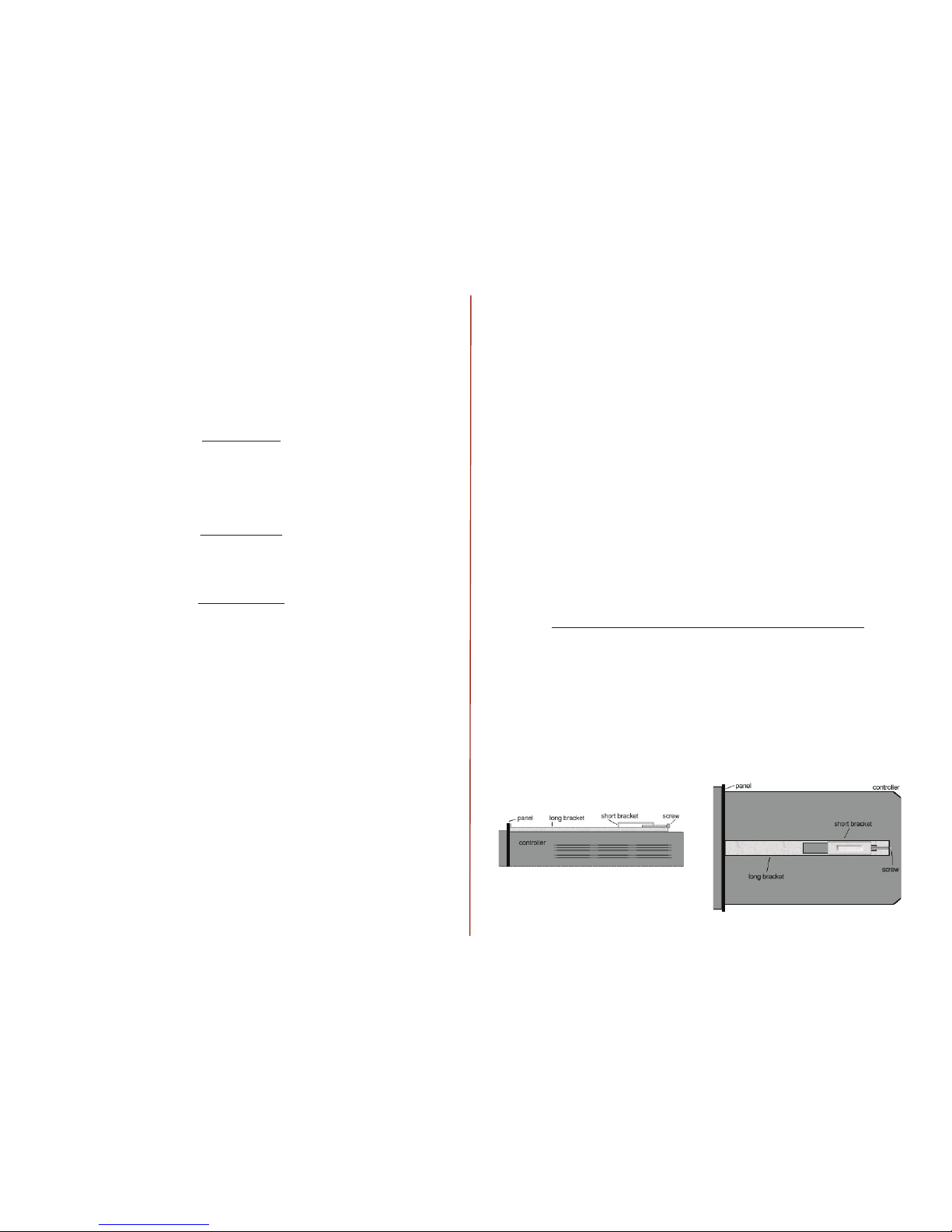
ATTACHING THE MOUNTING BRACKETS
1. Slide the controller through the hole in the panel.
2. From the rear of the controller, place one long bracket with the ridge side facing up, on the top of the
controller.
3. Place a short bracket, with the legs facing down, through the holes in the long bracket, and into the
holes in the controller. The hooked leg should be closer to the controller face.
4. Slide the long bracket towards the controller face, so that the front end is pressed against the panel.
5. Secure a screw from the hole in the long bracket through the hole in the short bracket. Tighten, but
do not overtighten.
6. Do the same for the bracket on the bottom of the controller. Tighten both brackets equally.
TOP VIEW
SIDE VIEW (of the top bracket)
 Loading...