

HM Digital CIC-152 User Manual
USER’S GUIDE
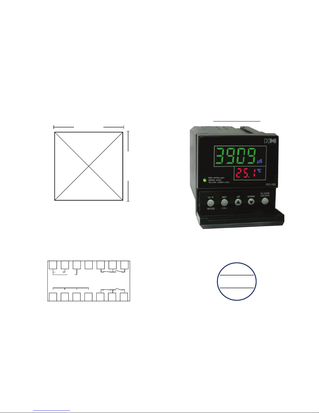
PANEL CUT-OUT DIAGRAM
M
H
D I G I T A L
®
CIC-152
DUAL CONTROL DOSING/INJECTION
TDS/EC CONTROLLER
1. Using a knife, cut the diagram out (cut on the outer part of the line).
2. Align the cut-out to your panel and draw cut marks.
3. Cut the hole in the panel to the precise dimensions of the cut-out:
2-5/8 in. x 2-5/8 in. (66.5 mm x 66.5 mm)
--> See the installation section for complete instructions.
CONTACT DIAGRAM
2 5/8 in. (66.5 mm)
2
5
/8 in. (66.5 mm)
8 9 10 11 12 13 14
1 2 3 4 5 6 7
220V
110V
N.C. N.O.
BLUE BLACKRED WHITE
SENSOR
POWER
RELAY (SWITCH) #2
N.C. N.O.
RELAY (SWITCH) #1
2 7
Thank you for purchasing HM Digital’s CIC-152. The CIC-152 is a TDS/EC controller that monitors and controls levels
of Total Dissolved Solids (TDS) or Electrical Conductivity (EC) in water. The controller has two programmable control
points (maximum limit (CP2) and minimum level (CP1)) to help maintain the TDS/EC within a designated range. If
the TDS/EC level is within the range, the controller will display a green light. Each control point can be used to
control a distinct device, or both can be used to control a single device. If the TDS/EC level descends to Control
Point 1 (CP1), the controller will activate a yellow warning light, and switch the dry contact position of Relay 1 from
the normal position (to operate a valve, pump, etc). Once the TDS/EC ascends over CP1, the light will revert to green
and switch the contacts of Relay 1 back to the normal position (normally open or closed). If the TDS/EC level rises to
Control Point 2 (CP2), the controller will activate a red warning light, and switch the dry contact position of Relay 2
from the normal position (to operate a valve, pump, etc). Once the TDS/EC level drops below CP2, the light will
revert to green and switch the contacts of Relay 2 back to the normal position (normally open or closed).
CONTACT INFO
BOX CONTENTS
SPECIFICATIONS
If you have any problems or questions regarding your controller, please contact HM Digital, Inc.
HM Digital, Inc. info@hmdigital.com
5819 Uplander Way www.tdsmeter.com
Culver City, CA 90230, U.S.A. 1-800-383-2777
1. Controller 3. Sensor cable (grey) 5. Mounting brackets
2. Sensor 4. Power cord (black) 6. U.S. plug adapter
EC Range: 0-9999 µS (µS/cm)
TDS Range: Model CIC-152 (NaCl): 0 - 4995 ppm (mg/L); Model CIC-152-4 (442TM): 0 - 8500 ppm
Temperature Range: 1-80oC; 33-176oF
Resolution: 0-999: 0.1 µS/ppm; 1000-9999: 1 µS/ppm
Accuracy: ±2% (of the reading); Thermometer: ±1oC, ±1.8oF
Conversion Factor: Model CIC-152: NaCl (avg. 0.5); Model CIC-152-4: 442TM (avg. 0.4 - 0.7)
Temperature Compensation: Automatic (ATC) (1-60oC)
Calibration: Digital by push button (manual ne-tuning in high ranges)
Control Points: Dual, controlled by on-screen up/down buttons (set points can be any point within
the range, but max (CP2) and min (CP1) cannot cross each other).
Control Point Relays: Dual, isolated, 2A, Max. 220V, resistive load 100,000 strokes
Relay Control: The unit will open or close a circuit via dry contacts when the ppm/µS level reaches
or surpasses each minimum or maximum control setting (simple switch). Each relay control can be
used to control a separate device.
Relay Coil Voltage (internal): 5V each (the connected devices need their own power source)
Alarms: Two (AP1 and AP2). Optional steady beep (set by user). Independent of control points.
Probe: ½” NPTF bushing
Cable Length: 3 meter (9.8 ft) shielded cable
Display: Bright tri-color L.E.D.
Power Supply: 110V/220V, ±10% Vac; 50/60Hz
Enclosure: Front and back with ABS
Environment: -10 to 50oC (4 to 122oF); RH max 95% non-condensing
Dimensions: 7.2 x 7.2 x 11.1 cm (2.8 x 2.8 x 4.4 in.)
THIS SPACE INTENTIONALLY LEFT BLANK
“442” is a registered trademark of the Myron L Company.
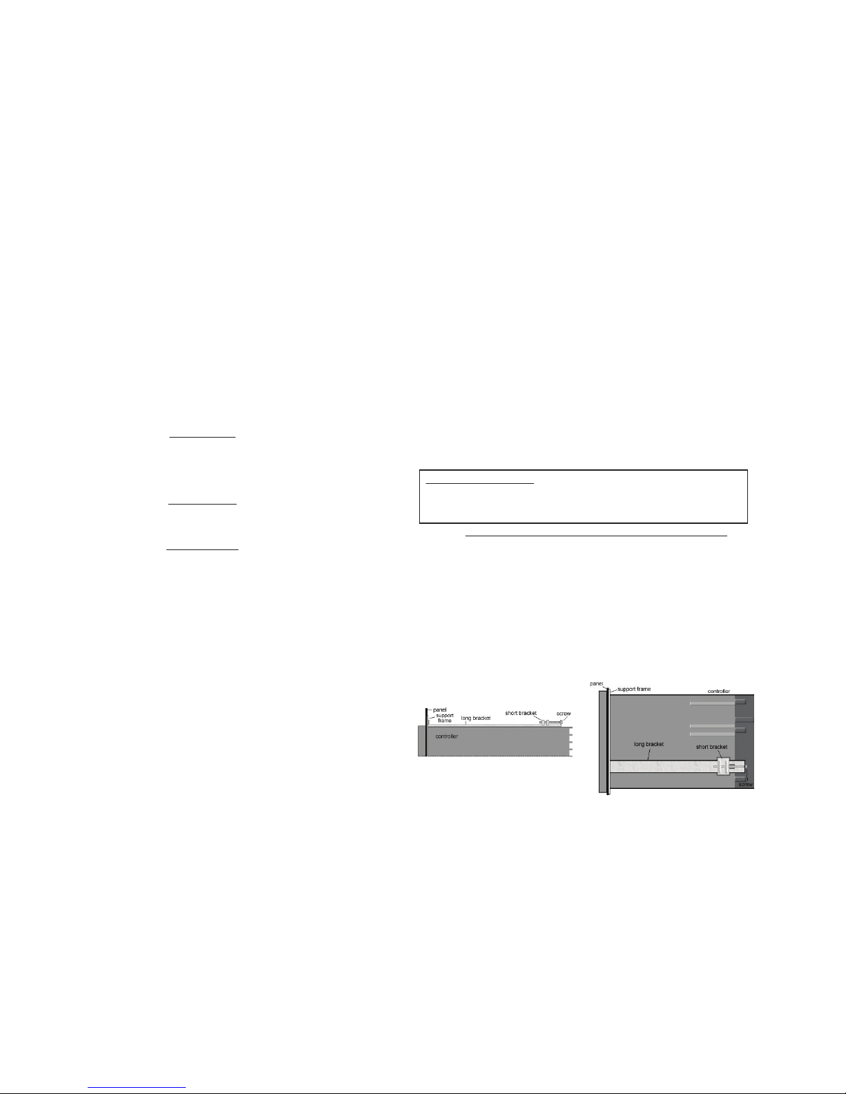
ATTACHING THE MOUNTING BRACKETS
1. Slide the controller through the hole in the panel.
2. From the rear of the controller, slide the metal square support frame over the controller, so that it is
pressed against the interior of the panel.
3. If not assembled, on the top of the controller, place one long bracket with the ridge side facing up.
Insert the short bracket into the slots on the controller, so that it ts snugly against the long bracket.
4. Slide the long bracket towards the controller face, so that the front end is pressed against the support
frame (or the panel, if not using the support frame).
5. Secure a screw from the hole in the long bracket through the hole in the short bracket. Tighten, but
do not overtighten.
6. Do the same for the bracket on the bottom of the controller. Tighten both brackets equally.
SIDE VIEW (of the top bracket)
TOP VIEW
User’s Guide Abbreviations
CP1: Control Point 1 (lower level set point)
CP2: Control Point 2 (upper limit set point)
R1: Relay 1 (Relay for CP1 - contacts 5, 6, 7)
R2: Relay 2 (Relay for CP2 - contacts 12, 13, 14)
AL1: Alarm 1 (lower alarm)
AL2: Alarm 2 (upper alarm)
 Loading...