

HMC HG User manual

HG-50/HG-80
OPERATING MANUAL
(Form: CE-014a-01)
WARNING
● Be sure to read this operation manual carefully and handle it properly.

Introduction
(1) No part of this document may be reproduced without permission.
(2) The contents of this document are subject to change without notice.
(3) This document has been carefully compiled. If you have any questions or require
information not covered in the manual, please contact :
HMC-Europe GmbH
Hafing 21
84549 Engelsberg
Tel.: +49 (0) 8634 625-994
Fax.:+49 (0) 8634 625 996
info@HMC-Europe.com
-1-

Read Carefully Before Using
● Determine the handling person responsible of this product.
● In this manual the following headings are applied to items to which great attention should be
given:
WARNING
CAUTION
IMPORTANT
△△△△
● Never use the autoclave to sterilize any of the following hazardous materials or substances with
NOTE
WARNING
alkali content. Sterilization of such objects can cause explosion, corrosion of the working
chamber or chamber piping, and deterioration of gaskets.
List of Hazardous Materials
① Explosive substances
・ Nitroglycol, nitroglycerin, nitrocellulose, and other explosive nitric esters.
: Items that will aid in proper operation of the equipment.
: Precaution indicating an imminent dangerous situation which if not
avoided may lead to death or serious injury.
: Precaution indicating a dangerous situation which if not avoided may
lead to moderate or slight injury.
: Indicates items you are strongly advised to obey.
・ Trinitrobenzene, trinitrotoluene, picric acid, and other explosive nitro compounds.
・ Peracetic acid, methyl ethyl ketone peroxide, benzoyl peroxide, and other organic peroxides.
② Ignitable substances
・ Metallic lithium, potassium, sodium, yellow phosphorous, phosphorus sulfide, and red
phosphorus.
・ Celluloids, calcium carbide (carbide), lime phosphide, and magnesium powder
・ Aluminum powder, magnesium powder, and metallic powders other than aluminum powder
・ Sodium dithionite (or sodium hydrosulfite)
③ Oxidizing agents
・ Potassium chlorate, sodium chlorate, ammonium chlorate, and other chlorates
・ ・ Potassium perchlorate, sodium perchlorate, ammonium perchlorate, and other
perchlorates.
・ Potassium peroxide, sodium peroxide, barium peroxide, and other inorganic peroxides
・ Potassium nitrate, sodium nitrate, ammonium nitrate, and other nitrates
・ Sodium chlorite and other chlorites
・ Calcium hypochlorite and other hypochlorites
④ Flammable substances
・ Ethyl ether, gasoline, acetaldehyde, propylene oxide, carbon disulfide, and other substances
whose flash points range from -30 to 0°C.
・ Methanol, ethanol, xylene, benzyl acetate (or amyl acetate), and other substances whose
flash points range from 0 to 30°C.
・ Kerosene, gas oil, turpenine oil, isopentyl alcohol (or isoamyl alcohol), acetic acid, and other
substances whose flash points range from 30 to 65°C.
⑤ Flammable gas (hydrogen, acetylene, ethylene, methane, ethane, propane, butane, and other
substances that are gases at a temperature of 15°C under 1 atmospheric pressure.)
-2-

●
When liquid with salt water and much salinity of salt agar etc.
spills in the chamber, blowing, discharge water in the
chamber and wipe up drop of water around the lid gasket
beautifully.
It causes the corrosion of the chamber and the piping when
leaving just as it is
●
Check that the pressure is below "0MPa" before opening the
0
0.1
0
Pressure
gauge
0.2
0.3
0.4
lid.
●
Absolutely do not attempt to remodel or alter this product.
CAUTION
● Foreign matter (metals, liquid) may enter through the vent hole. Operating the equipment with
such foreign matter inside may cause trouble with the equipment, fire or electric shock.
● Do not forcibly bend, twist, tie or extend the power cord. Do not place heavy objects on the cord.
A damaged cord or exposed wire can cause fire or electric shock.
● Never connect the power cord to a power supply other than one of the rated voltage. Connection
to such a power supply can cause fire or electric shock.
● If grounded socket is unavailable, ground the equipment using a separate ground wire before
connecting the power cord to the power source.
● Connect the grounding cable correctly to the Type D or higher-grade grounding terminal. Never
connect the grounding wire to gas pipes or water pipes.
● Close the lid after confirming that no foreign matter is adhering to the section contacting the lid
gasket. Foreign matter in this section can cause vapor leaks.
● When using a waste processing bag or other kind of bag and disinfecting, place the bag in the
metal mesh holder and then insert it into the chamber. Using the bag “as is” can cause excessive
temperatures, pressures, lack-of-water, etc.
● Be careful not to pinch your hands when closing the lid.
● Do not touch the lid or lid cover when opening or closing the lid.
● Do not put your face or hands close to the chamber when lifting the lid after operations are
complete; steam will gush out of the chamber.
● The lid, chamber, gasket and panel are extremely hot immediately after the completion of
operation. Do not touch the equipment or you may get burned.
● Put on heat insulating gloves before removing a substance from the chamber. Do not put hands
into the chamber until the steam has been vented.
● Some time is required for liquids to cool. Be sure to check that the temperature has dropped
sufficiently before unloading a liquid from the chamber or burns can result.
● Do not unload the exhaust bottle or drain the chamber when the chamber is under pressure.
Boiling water or steam may gush out causing burns.
● Do not remove the exhaust bottle before water in the bottle has sufficiently cooled.
● If any abnormality occurs (e.g. abnormal sounds, smells, smoke), immediately shut the power off.
After checking to see that the abnormal condition does not continue, call our authorized
distributor in your region.
● If the display reading changes between the steps, turn the POWER switch off then on again. If
the problem continues, turn the power switch off and call our authorized distributor in your region.
-3-

How to Read this Manual
● This operation manual consists of the following sections covering the information required for
proper operation of the Autoclave HG-50.
Chapter 1. What is the Autoclave HG-50? :
This section describes the uses and features of the product and the names and functions of its
parts.
Chapter 2. Installation :
This section explains where the equipment should be installed and how to install it. The product
incorporates precision parts, so be sure to follow the instructions covered in this chapter.
Chapter 3. Operation Method :
This section illustrates how to change various set values, and describes operations before
starting the equipment and after automatic operation. This section also covers the display and
performance of the equipment during automatic operation.
Chapter 4. Maintenance and Service :
This section explains the methods for draining water from the exhaust bottle or chamber,
cleaning the body of the equipment, and parts replacement.
Chapter 5. Specifications
This section includes dimensions, power consumption and working range of the product.
Refer to this section as is required.
Chapter 6. Troubleshooting
This section covers troubleshooting procedures for the product. If you encounter a problem, read
this section first.
Appendix
This section contains information on the warranty and a glossary of terms that appear in the
manual. Please refer to this section when necessary.
-4-

CONTENTS
Introduction·················································································································· Ⅰ
Read Carefully Before User Inspection ···································································· Ⅱ
How to Read this Manual ··························································································Ⅳ
CONTENTS··················································································································Ⅴ
Chapter 1. What is the Autoclave HG-50?·············································1
1. Product Uses···········································································································1
2. Product Features·····································································································1
3. Names and Functions of Each Part·········································································1
Chapter 2. Installation·············································································3
1. Installation Instructions····························································································3
2. Installation Procedure······························································································4
Chapter 3. Operation Method·································································6
Basic Operation Method ··························································································6
1. Power······················································································································ 7
2. Pouring Water··········································································································7
3. Loading Substance··································································································8
4. Selection of Course and Program············································································ 9
5. Changing Set Values (Registering of Values by Customer)··································· 11
6. Changing Function Setting ····················································································14
7. Reservation Operation··························································································· 16
8. Starting Operation·································································································· 18
9. Unloading ··············································································································19
10. After Completion of Operation ·············································································19
11. To Interrupt Operation··························································································20
12. If Power Supply is Cut Off during Operation························································20
13. Operation of Cycles····························································································· 20
Chapter 4. Maintenance and Service···················································24
1. Draining Exhaust Bottle························································································· 24
2. Draining Chamber ·································································································25
3. Cleaning Chamber································································································· 25
4. Cleaning Body······································································································· 26
5. Water Supply to Cooling Tank················································································ 26
Chapter 5. Specifications ·····································································27
Chapter 6. Troubleshooting ·································································28
1. Error Detection (Alarms) ······················································································28
2. Early Troubleshooting···························································································· 29
Appendix································································································30
1. Fast wearing parts································································································· 30
2. Glossary ················································································································30
3. Limited Warranty ···································································································31
-5-
Chapter 1. What is the Autoclave HG-50?
1. Product Uses
・ The product is used to sterilize substances which can withstand high temperature and high
pressure steam such as tools of glass, ceramic, metal or rubber, water, media, reagents and
liquid medicines (Mode 1 – 3) .
・ The product is also used to liquefy media (Mode 4).
2. Product Features
・ In order to secure safety, the product is provided with a lid cover around the section that
becomes hot during operation,.
・ The lid of the product is opened and closed automatically. It is not necessary to bring your
hands near the chamber port to open or close the lid. The safety has been improved this way.
・ The agar cycle, which prevents solidification of sterilized media when they are not taken out
immediately, and the dissolution cycle, which dissolves solidified media, are provided.
・ When the exhaust valve (the opening of the exhaust valve) is set, fine exhaust is conducted
automatically after sterilization.
・ Steam that comes out of the exhaust valve during air release and exhaust is cooled in the
cooling tank to minimize the quantity of steam that is emitted into the room.
・ The temperature, at which the loaded substance cannot be taken out, can be set for safety within
the range of 60-97℃ for each cycle and program number.
・ A reservation timer is provided to permit operation startup at any desired time within the range of
1 hour to 99 hours later.
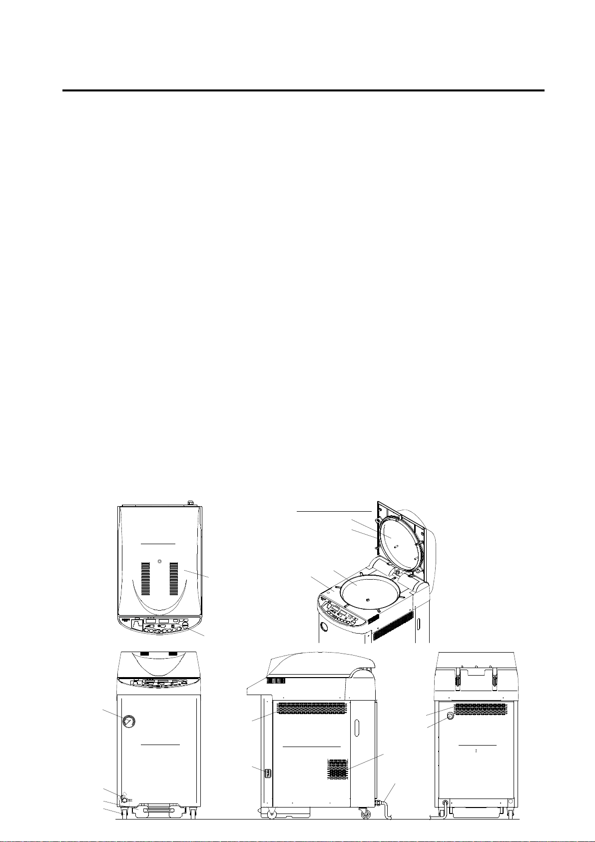
3. Names and Functions of Each Part
●
● Outer View of Body
●●
Top View
Lidcover
Operation panel
Whenthe lid is open
Gasket
Top panel
Chamber
Lid
Pressure gauge
Drain valve
Drain bottle
Caster
0.2
0.3
0.1
0.40
Front View
Vent hole
Main power switch
Right Side View
-6-
Vent hole
Coolingtank
Water filler port
Coolingfan
Powercord
Rear View
F. L
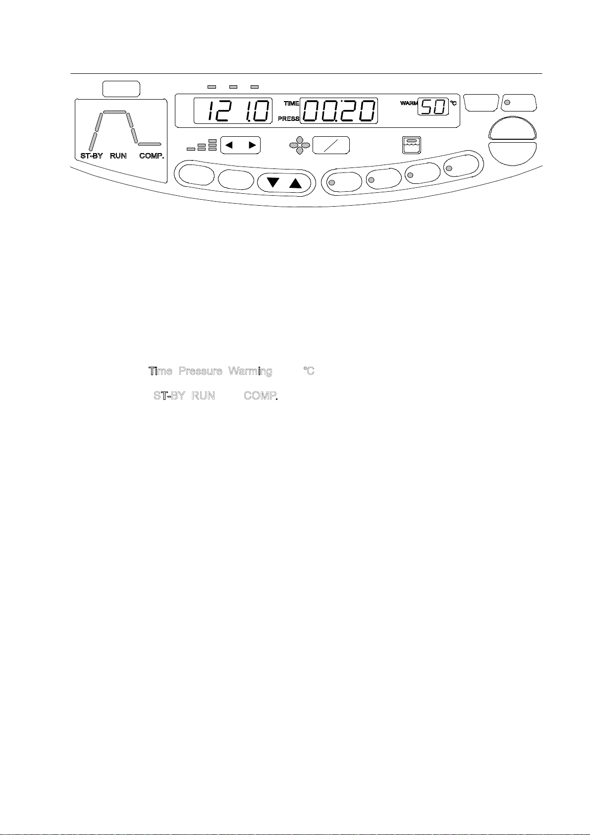
●
● Operation panel
●●
HEAT
⑧
POWER
STERI/DISSOL
EXHT.
⑥
⑤
WARM
PROGM1
TEMP
①
EXHT.
F
U
N
⑫
⑲
2 3
℃
④
⑮
C
.
S
E
T
⑬
FAN
⑯
⑭
② ③
Hr/min.
MPa
OFF
L
DRAINBOTTLE
Q
.
I
A
G
A
ON
④ ④
⑦
L
O
S
R
⑪
⑨ ⑩
LID
℃
CLOSE
L
O
S
S
I
D
D
I
LID
OPEN
⑰
START
STOP
⑱
① Digital Display (Temperature)
The digital display indicates the sterilization set time in the standby state, and it indicates the
chamber temperature during operation.
② Digital Display (Time and Pressure)
The digital display indicates the set time, reservation time, etc. in the standby state, and it indicates
the pressure inside the chamber, time remaining until completion of sterilization, and time
remaining until completion of warming during operation.
③ Digital Display (Warming)
The digital display indicates the warming set temperature, function number, etc. in the standby
state, and it indicates the error when it is detected.
④ Unit Display (
, , , and )
The unit corresponding to the current digital display illuminates.
⑤ State Display ( , , and )
The state display indicates the present state.
⑥ Cycle Display
The action cycle of the preset cycle illuminates, and the current cycle blinks.
⑦ Drain Bottle Display
The red light blinks when the drain bottle is full, and the green light illuminates when it is not full.
⑧ POWER Switch
Used to turn on or off the power to the autoclave.
⑨ LID CLOSE Switch
Used to close the lid.
⑩ LID OPEN switch
Used to open the lid. When the lid can be opened, a green light comes on, and when the lid
cannot be opened because the chamber is hot and highly pressurized, a red light comes on.
⑪ Cycle Switch
Used to select the cycle and program number.
⑫ FUNC. Switch
Used to change and confirm the setting of respective functions.
⑬ SET switch
Used to change and confirm the set value.
⑭ Set Value Increase/Decrease Switch (▲ ▼)
Used to increase or decrease the set value.
⑮ Exhaust Level Switch (ì í)
Used to change the exhaust level.
⑯ FAN Cooling ON/OFF Switch
Used to change fan cooling ON/OFF setting.
⑰ START Switch
Used to start operation.
⑱ STOP Switch
Used to stop operation.
⑲ PROGM Display
The display indicates the present program.
-7-
Chapter 2. Installation
IMPORTANT
● If the equipment is installed in a place which is 800m or higher than sea level (i.e. under low
pressure in mountainous areas), the settings must be changed. In this case, be sure to contact
our authorized distributor in your region. Do not use the equipment before changing.
● When relocating the product, close the lid so that it will not move, and then remove the drain
bottle and power cord.
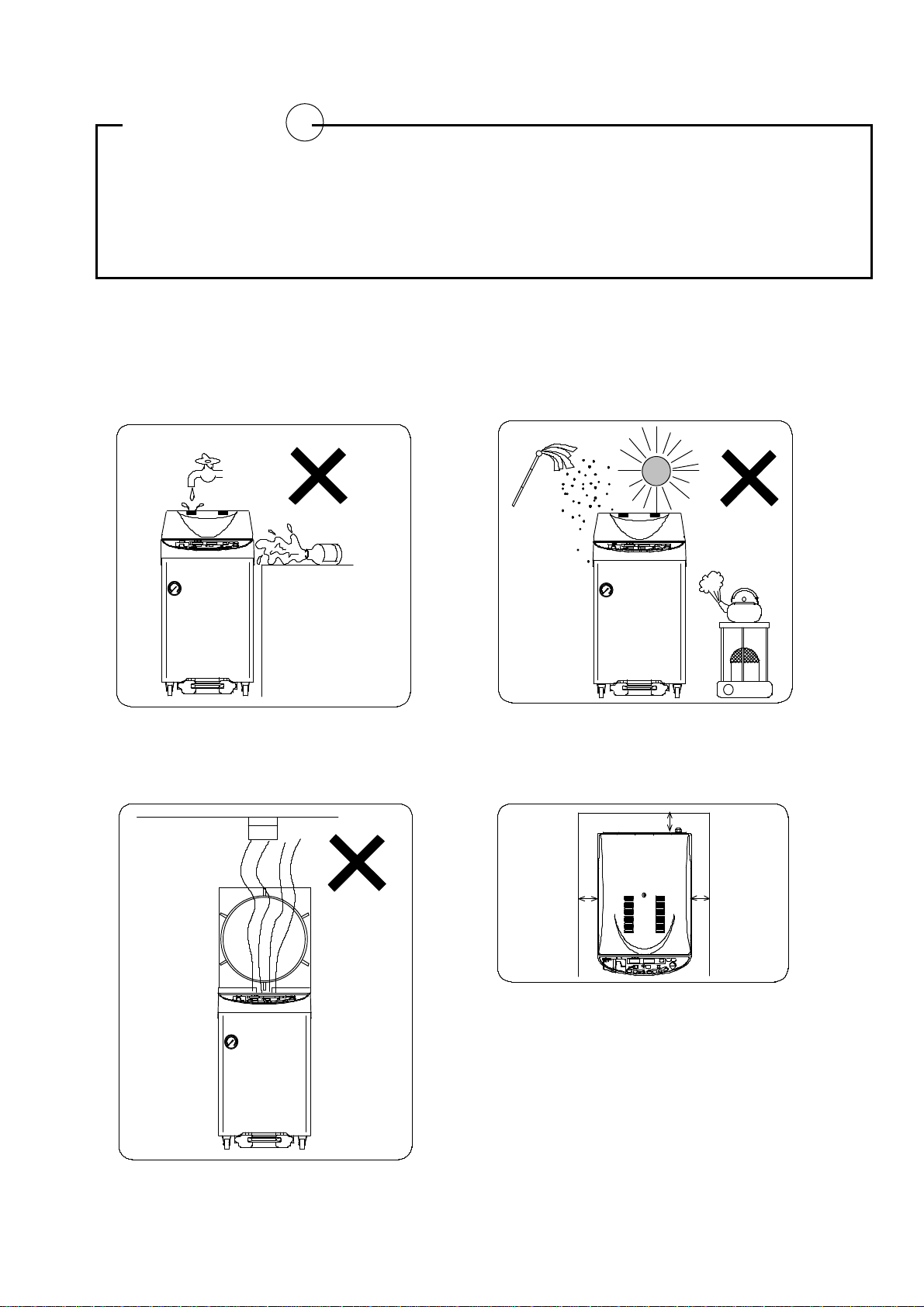
1. Installation instructions
①
Avoid installing the equipment in a place where its
body may be exposed to water or chemicals, or
where corrosive and explosive gases may be
produced neareby.
②
Avoid installing the equiopment in a place which is
exposed to hight humidity, direct sunlight or much
dust.
0.2
0.3
0.1
0.40
③
Avoid placing the equipment directly under a fire
detector. If you open the lid immediately after
completion of operation, steam comes out of the
working chamber, and may activate the detector.
0.2
0.3
0.1
0.4
0
0.2
0.3
0.1
0.40
④
Arrange the equipment with a clearance of 10 cm
or wider on the right side and 12 cm or wider on
the rear side to prevent the vent hole from
being blocked.
12cmor more
10cmor more
⑤
Avoid an installation place which is subject to impact
10cmor more
or vibration.
⑥
Place the unit in a level, firm place.
⑦
Avoid installing in a place which is subjected to a room
temperature of 5℃or below or 35℃or above.
-8-
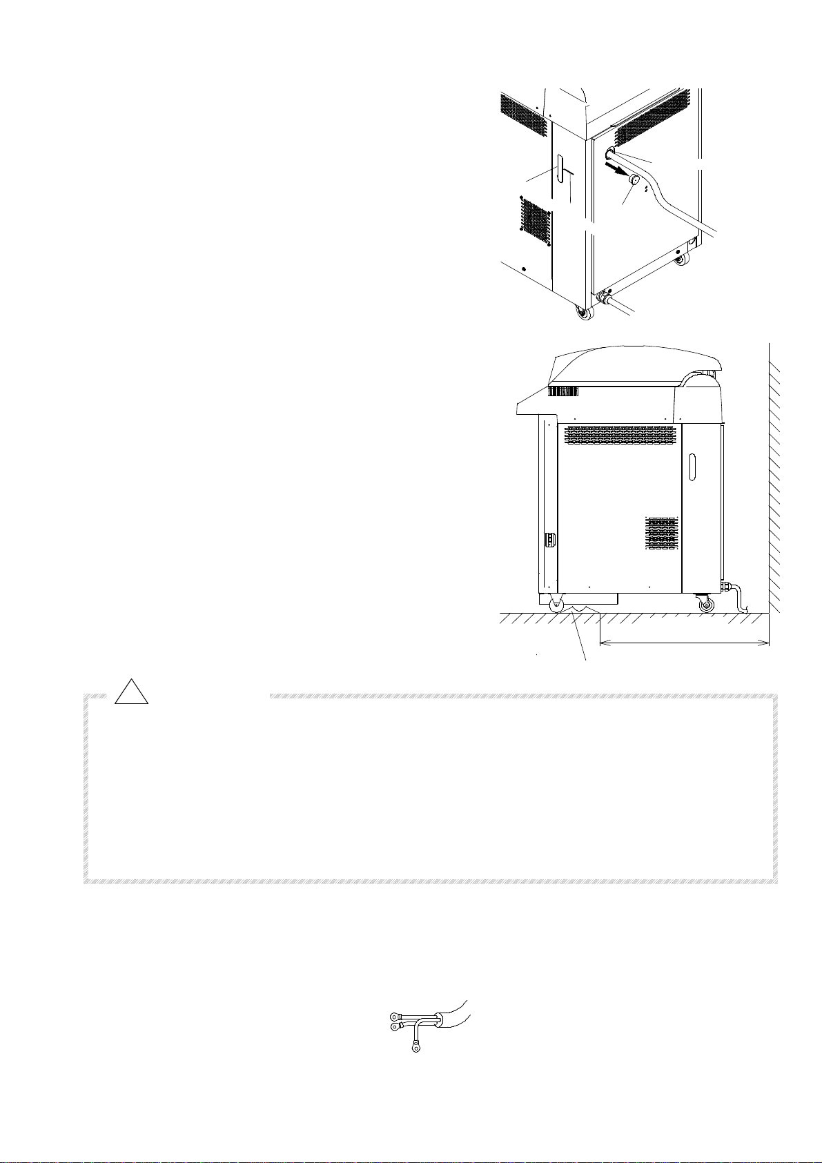
2. Installation Procedure
① Pour water into the cooling tank.
・ Remove the cap from the water filler port at the
back of the unit, and pour water through the
water filler port by using a hose, etc. up to the
center of the level confirmation window at the
side of the unit.
After water supply, return the cap back to the
original position.
(Hoses, etc. are not provided. Please prepare
them by yourself.)
② Put casters on the caster stoppers so that the
unit will not move.
・ Place two casters at a position more than 64 cm
away from the wall, and push the unit so that the
front casters will be on the stoppers.
・ Be sure to set the caster stoppers, otherwise the
full water function of the drain bottle may not be
activated.
③ Connect the power cord to the rated power supply.
W
a
t
e
r
l
e
v
C
e
l
e
c
n
h
t
e
e
r
c
k
Cap
w
i
n
d
o
w
Water filler port
・ Be sure to connect the grounding wire.
64 cm or more
CAUTION
Caster stopper
● Do not forcibly bend, twist, tie, or extend the power cord. Do not place heavy objects on the cord.
A damaged cord or exposed wire may cause fire or electric shock.
● Never connect the power cord to a power supply with a voltage other than the rated voltage.
Connection to such a power supply may cause fire or electric shock.
● If not plugging the sterilizer into a grounded socket, ground the equipment separately before
connecting it to the power source.
● Never ground to a gas pipe or vinyl chloride water service pipe.
・ Connect the unit to a power unit of as below and to ground the Green/Yellow grounding wires.
・ AC100V: 20Amp or more, AC110V: 19Amp or more, AC120V: 17Amp or more,
・ AC220V: 10Amp or more, AC230 and AC240V : 9Amp or more.
CONNECT TO RATEDVOLTAGE
White
Black
Connect
to ground
Green/Yellow
-9-
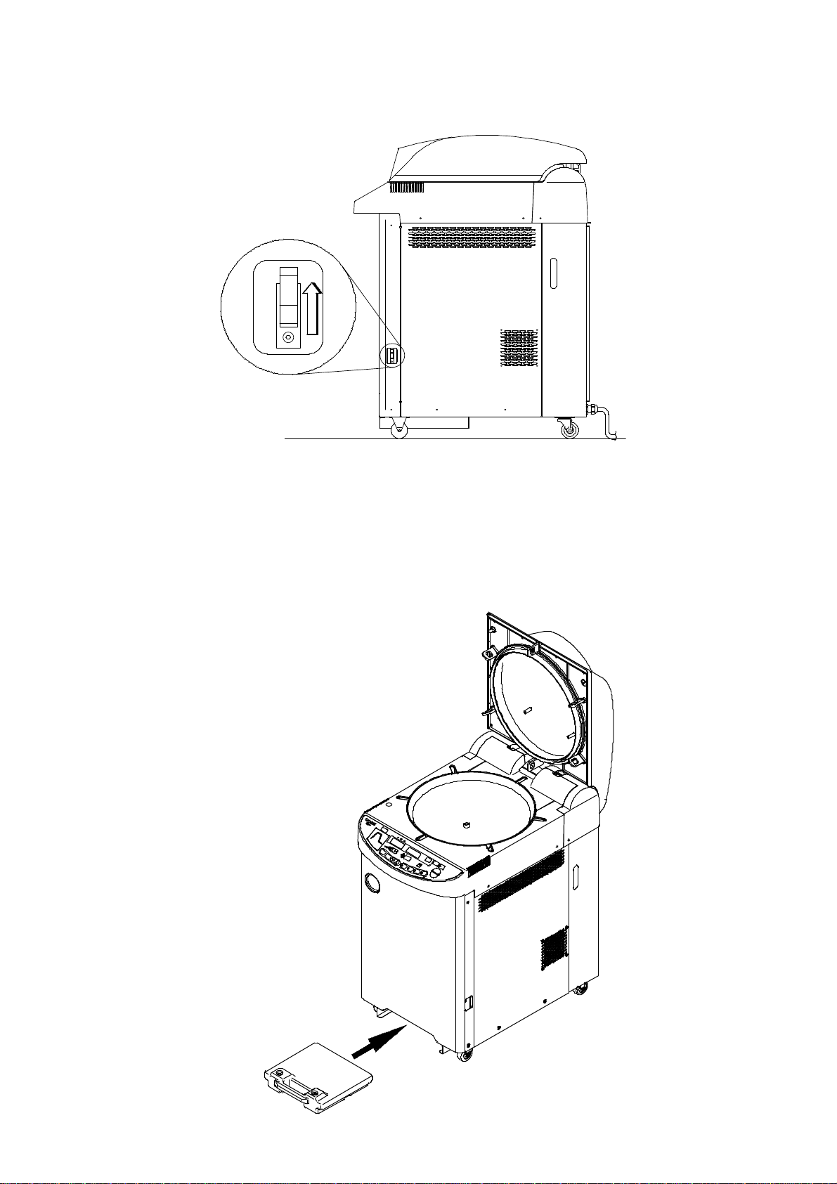
④ Turn ON the main power switch.
・ Raise the lever of the main power switch at the right side of the unit.
Main powerswitch
Raise.
⑤ Referring to “Chapter 3, Operation Method”, open the lid and take out the accessories.
⑥ Place the bottom plate in the chamber.
⑦ Attach the drain bottle.
・ Check that there is no foreign substance or irregularity on the floor where the drain bottle is
to be set.
Drain bottle
-10-

Chapter 3. Operation Method
Basic Operation Method
Turn “ON” Power Switch
▼
Open the lid
▼
Pour water
▼
Load substance
▼
Check and select cycle
▼
Check and change set
values
▼
Set Turn-on Timer
▼
――――――
―――――
――――――
(When starting operation by Turn-on Timer)
See "1. Turning ON Power Switch” on page 7.
See "2. Pouring Water" on page 7.
See "3. Loading Substance" on page 8.
See "4. Selection of Cycle and Program" on page 9.
See "5. Changing Set Values" on page 11.
See “7. Checking and Setting of Turn-on Timer”
on page 16
Start operation
▼ ▼
Check if operation is
completed
▼
Open the lid
▼
Unload substance
▼
Turn “OFF” Power Switch
―――――
――――――
See "8. Starting Operation" on page 18.
See "9. Unloading" on page 19.
See "10. After Completion of Operation" on page 19.
-11-
 Loading...