

Page 1

Revision 2016-1-1
Copyright ©, 2016 by HMA Group.
The information contained in this document is subject to change without prior notice.
Page 2

Page 2 of 19
Contents
1. Introduction:................................................................................................................................................................ 3
2. Specifications: ............................................................................................................................................................. 4
3. Vibrating Wire Piezometer Operation .............................................................................................................. 5
4. Calibration and Interpreting Readings ............................................................................................................. 6
4.1 Electrical Connection ............................................................................................................................................. 6
4.2 Calibration Sheet Interpretation ...................................................................................................................... 7
4.3 Data Reduction ......................................................................................................................................................... 8
4.4 Pressure Head/Water Level Calculation ....................................................................................................... 9
4.5 Barometric Compensation .................................................................................................................................. 9
5. Installation Procedure .......................................................................................................................................... 10
5.1 Installation in Standpipes ................................................................................................................................. 10
5.2 Installation in Boreholes (traditional sand layer method) ................................................................. 10
5.3 Installation in Boreholes (direct grout method) ..................................................................................... 11
5.4 Installation in Fills and Embankments ....................................................................................................... 12
6. Instrument Troubleshooting ............................................................................................................................. 13
7. Field Installation Records Sheet ....................................................................................................................... 14
8. Standard Temperature vs Resistance Values ............................................................................................. 15
9. Definitions ................................................................................................................................................................. 16
10. HMA Group Conditions of Supply ............................................................................................................... 17
Important Note
Always ensure that the zero reading is taken at installation.
For further information, see the data reduction and installation sections of this manual.
Page 3
Page 3 of 19
1. Introduction:
The HMA Geotechnical Vibrating Wire Piezometer has been designed to easily measure
remote fluid pressures in earthen masses.
The Vibrating Wire Piezometer functions on the principle of tensile wire vibration. As the
native reading taken is a frequency measurement, water penetration, temperature
variations and contact resistance do not affect the output unlike several other types of
electrical instrumentation.
The piezometers can be read using a handheld vibrating wire readout unit , or a standalone
datalogger.
Providing the HMA Geotechnical Vibrating Wire Piezometers are installed in accordance
with the prescribed techniques, the instrument has the capacity to operate indefinitely.
Page 4

Page 4 of 19
2. Specifications:
Piezometer
Pressure Ranges (kPa)
350, 700,1000 2000, 3000, 5000
Over Range
1.5 x Rated Pressure
Resolution
0.025% full scale
Accuracy
< 0.5% full scale
Operating Temperature
-20 to 60⁰C
Filters
0.5 and 20 micron
Dimensions
19mm dia, 136mm long
Weight
0.11kg
Signal Output
Continuous Gauge Frequency
Frequency Range
2000 - 3500 Hz
Cable
Description
2 Pair Twisted 22AWG
Conductor Gauge
22AWG
Insulation Material
PP Compound
Nominal Thickness (mm)
0.2
Nominal OD (mm)
1.2
Drain Wire Gauge
24AWG
Applicable Standards
AS/NZS 1125, AS/NZS 3808
Electrical Properties
Max. Conductor DC Resistance @
20⁰C
56.95 Ohms per km
Voltage Test: Core to Core
1kV AC for 1 Minute
Voltage Test: Core to Screen
1kV AC for 1 Minute
Mechanical Properties
Operating Temperature
-15 to 90⁰C
Min. Bend Radius
63mm
Approximate Mass
5.83kg/100m
Page 5

Page 5 of 19
3. Vibrating Wire Piezometer Operation
The HMA Geotechnical Vibrating Wire Piezometer provides a reliable static pressure output to be
utilised in a number of applications, such as:
• Water level monitoring
• Soil deposit pressure monitoring
• Compacted fills for dams
• Mining applications (Dewatering, Pumping, Backfill)
• Slope stability
• Seepage
The piezometers are based upon the principle of vibrating wire resonance. The instrument consists
of a vibrating wire element connected to a sensitive, perpendicular diaphragm. Exerting pressure,
such as pore water pressure, on the diaphragm will cause it to deflect therefore altering the tension
and corresponding resonant frequency of the vibrating wire.
Each time a measurement is taken, electromagnetic coils adjacent to the vibrating wire pluck the
instrument wire and then measure the resonant frequency of the wire. The frequency of the wire is
read by a handheld readout or a datalogger.
Figure 1. Vibrating Wire Piezometer construction
Hand held readouts and dataloggers usually return a Digits (B) reading, being the frequency
squared divided by 1000 (Hz2 x 10-3) as this value is directly proportional to the pressure applied to
the diaphragm. By using vibration frequency as a measurement method, water penetration, lead
wire resistance and contact resistances are deemed negligible. Long runs of instrumentation cable
can be installed also, unlike other forms of piezometers.
The stainless steel housing of the piezometer ensures resistance to corrosive environments.
Standard filters are 20-micron pore diameter sintered stainless steel. However, a variety of filter
permeabilities are available to meet different application requirements.
Page 6

Page 6 of 19
4. Calibration and Interpreting Readings
Prior to shipment each piezometer is individually calibrated with respect to applied pressure.
Although comparatively minimal, further corrective calibrations regarding changes in barometric
pressure and temperature may also be necessary. It should also be noted that the manufacturers
factory elevation is 110 metres above sea level, meaning that further corrections for site elevation
may be required.
The site test reading of each piezometer should be checked and noted upon delivery. Theoretically
once calibrated the site test reading should closely match the factory reading.
All Geotechnical Systems Vibrating Wire Piezometers have been calibrated to international
standards using either pneumatic or deadweight pressure testers. Both testers are traceable to the
national standards at the National Bureau of Standards (U.S.A).
Each Vibrating Wire Piezometer ships with a calibration sheet provided by HMA Geotechnical.
4.1 Electrical Connection
Figure 2. Typical HMA Geotechnical Vibrating Wire Piezometer cable
Conductor Definitions
Red
Vibrating Wire
Black
Vibrating Wire
Green
Thermistor
White
Thermistor
Page 7
Page 7 of 19
4.2 Calibration Sheet Interpretation
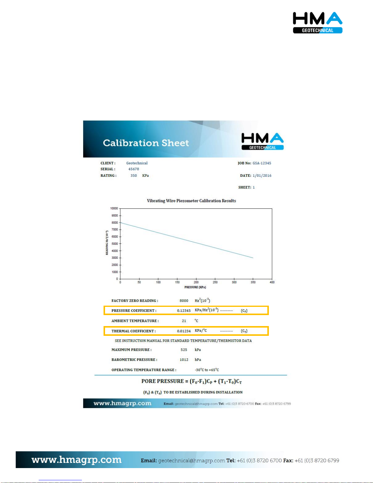
HMA Geotechnical supplied piezometers include basic information such as the client name, job
number, serial number, and pressure rating at the top of the page.
These are important records to keep, please ensure these sheets are filed away safely.
You will need to refer to the calibration sheet when performing calculations to deduce the pore
pressure. The key coefficients have been highlighted below that will be required when performing
pressure calculations.
Figure 3. Typical HMA Geotechnical calibration sheet
Page 8

Page 8 of 19
4.3 Data Reduction
To calculate the pore water pressure being applied to the piezometer the following formula should
be used:
P = (F0 – F1)CP+ (T1 – T0)CT
Where P = Pressure (Dependant on pressure coefficient, usually kPa)
F0 = Zero reading prior to installation taken at site (Hz2 x 10-3)
F1 = Current piezometer reading (Hz2 x 10-3)
CP = Pressure coefficient (kPa / Hz2 x 10-3)
CT = Temperature Coefficient (kPa / oC)
T1 = Current temperature reading (oC)
T0 = Zero temperature reading prior to installation taken at site (oC)
Refer to “Standard Thermistor Resistance/Temperature tables” table to determine the temperature
from the resistance reading from the vibrating wire piezometer’s internal thermistor.
Note: The zero reading must be taken on site and is detailed in the
installation section of this manual.
Do not use the factory reading unless there is no other option. While it is possible to use this value
in the event that a zero reading has not been taken prior to installation on site, data will not reflect
the true pressure experienced by the transducer.
Page 9

Page 9 of 19
4.4 Pressure Head/Water Level Calculation
The pressure head is calculated by dividing the kilopascals value taken from a Vibrating Wire
Piezometer by the specific weight of water.
Table 1 indicates appropriate values with an example given below.
Degrees Celsius
Specific Weight (kN/m3)
0
9.805
5
9.807
10
9.804
15
9.798
20
9.789
25
9.777
30
9.765
40
9.731
50
9.69
60
9.642
70
9.589
80
9.53
90
9.467
100
9.399
Table 1. Temperature vs Specific Weight
Example 1
A Piezometer is reading 140kPa at 20 degrees Celsius. The pressure head is found by dividing
140kPa by 9.789.
140kPa/9.789 = 14.3m Pressure Head
4.5 Barometric Compensation
In some instances, it will be necessary to compensate for barometric pressure changes.
If a Vibrating Wire Piezometer is installed in an open borehole, small fluctuating pressure changes
may be due to the barometric pressure. This can be overcome by using lower pressure vented
piezometers, which utilise a different style of cable inclusive of a vent tube from the instrument to
the top of the hole. The vent tube is terminated with a desiccant chamber to prevent moisture
ingress. HMA Geotechnical can supply these piezometers when requested.
Page 10

Page 10 of 19
5. Installation Procedure
5.1 Installation in Standpipes
To install the piezometer in open standpipes the transducer is normally lowered to the surface of
the water and slightly immersed to allow the unit to come to thermal equilibrium (approximately 5
minutes). A zero reading is taken and the piezometer can then be lowered to the desired position in
the standpipe.
In situations where packers are used in standpipes the same sequence as above should be noted
and special care should be taken to avoid cutting the cable jacket with the packer since this could
introduce a possible pressure leakage path or short circuit the instrument.
5.2 Installation in Boreholes (traditional sand layer method)
HMA Geotechnical piezometers can be installed in boreholes in either cased or uncased holes.
Careful attention must be paid to borehole sealing techniques if pore pressures in a particular zone
are to be monitored.
Boreholes should be drilled either without drilling mud or with a material that degrades rapidly
with time, such as Revert. The hole should extend from 150 to 300mm below the proposed
piezometer location and should be washed clean of drill cuttings.
The bottom of the borehole should then be back filled with clean sand to a point 150mm below the
desired piezometer tip location.
The piezometer can then be installed, as delivered, or preferably encapsulated in a filter cloth bag
containing clean, saturated sand.
It is then lowered to the surface of the water and slightly immersed to allow the unit to come to
thermal equilibrium (approximately 5 minutes). A zero reading is taken and the piezometer can
then be lowered to the desired position in the borehole.
While holding the instrument in position (a mark on the cable is helpful) clean sand should be
placed around the piezometer and to a point 150mm above it.
Immediately above the collection zone the borehole should be sealed with either alternating layers
of bentonite and sand back fill tamped in place for approximately 300mm followed by common
back fill or by an impermeable bentonite – cement grout mix.
If multiple piezometers are to be used in a single hole, the bentonite-sand plugs should be tamped
in place below and above the upper piezometers and also at intervals between the piezometer
zones. When designing and using tamping tools, special care should be taken to ensure that the
piezometer cable jackets are not cut during installation.
It should be noted that as the vibrating wire piezometer is basically a no flow instrument, collection
zones of appreciable size are not required and the piezometer can in fact, be placed directly into
most materials provided that the fines are not able to migrate through the filter.
Page 11

Page 11 of 19
5.3 Installation in Boreholes (direct grout method)
HMA Geotechnical piezometers can be installed in boreholes in either cased or uncased holes.
Careful attention must be paid to borehole sealing techniques if pore pressures in a particular zone
are to be monitored.
Boreholes should be drilled either without drilling mud or with a material that degrades rapidly
with time, such as Revert. The hole should extend from 150 to 300mm below the proposed
piezometer location and should be washed clean of drill cuttings
Typically a number of piezometers will be installed within the same borehole when using the direct
grout method. Piezometers are typically installed in deep boreholes (up to 800m) using this
technique.
Due to the long cable lengths and the associated self weight induced strain on the piezometer cables
it is advisable to use catenary cable to support the piezometer cables down the borehole. The
piezometer cables are fixed to the catenary cable using cable ties at intervals of 1 to 2 metres.
The grout tremie tubes also need to be attached to the catenary wire. It is important to know at
what lifts the grout will be placed as well as how many grout tubes are required. It is also
important not to over pressurise the piezometers during installation as this may permanently
damage the piezometers.
Please note the piezometers have an over range 1.5x that of the specified pressure range. However,
the piezometer is only calibrated to is specified pressure range and not the over range.
The porous filter is removed from the piezometer tip and the annulus is fully filled with silicon
greasing making sure that all air bubbles are removed. A rubber diaphragm (can use cut finger tip
from a rubber glove) is then placed and fixed firmly, over the silicon grease filled annulus, to the
stainless steel housing of the piezometer. The piezometer can then be installed down (silicon
greased filled annulus pointing down the borehole.
It is then lowered (with catenary cable attached) to the surface of the water slightly immersed to
allow the unit to come to thermal equilibrium (approximately 5 minutes). A zero reading is taken
and the piezometer can then be lowered to the desired position in the borehole.
Once the piezometers are all in position the grout can be pumped down the first (deepest) grout
tube. As mentioned earlier it is important not to over pressurise the piezometers with the grout
during installation. Please note that typically the specific gravity of a bentonite/cement grout is
about 1.6. Once the first lift of grout has been placed it should be left to cure overnight.
The procedure can be repeated for the other piezometers in the same borehole. It is good practice
to continually check the piezometer readings during the grouting process.
Once the cables have been all grouted in and the grout has cured the piezometers can now be read.
Page 12

Page 12 of 19
5.4 Installation in Fills and Embankments
HMA Geotechnical piezometers are normally supplied with direct burial cable suitable for
placement in fills such as highway embankments and dams, both in the core and in the surrounding
materials, each installation must be treated separately.
In installations in non-cohesive fill materials the piezometer may be placed directly in the fill or, if
large aggregate sizes are present, in a saturated sand pocket in the fill. The cable should be similarly
protected from the large aggregate.
In fills such as impervious dam cores where sub-atmospheric pore water pressures need to be
measured as opposed to the pore air pressure, a ceramic tip with a high air entry value is required
and should be carefully placed in direct contact with the compacted fill material.
If only the pore air pressure is required then the low air entry tip is acceptable. It should be noted
that the low air entry tip measures the air pressure when there is a difference between pore air
pressure and pore water pressure, the difference between the two pressures is due to the capillary
suction of the soil.
The general consensus is that it is normally of no consequence to embankment stability. As a
general rule the low air entry tip suitable for most routine measurements and, in fine cohesive soils,
sand pockets should not be used around the piezometer tip.
The zero reading should be taken when the instrument has been installed.
Page 13
Page 13 of 19
6. Instrument Troubleshooting
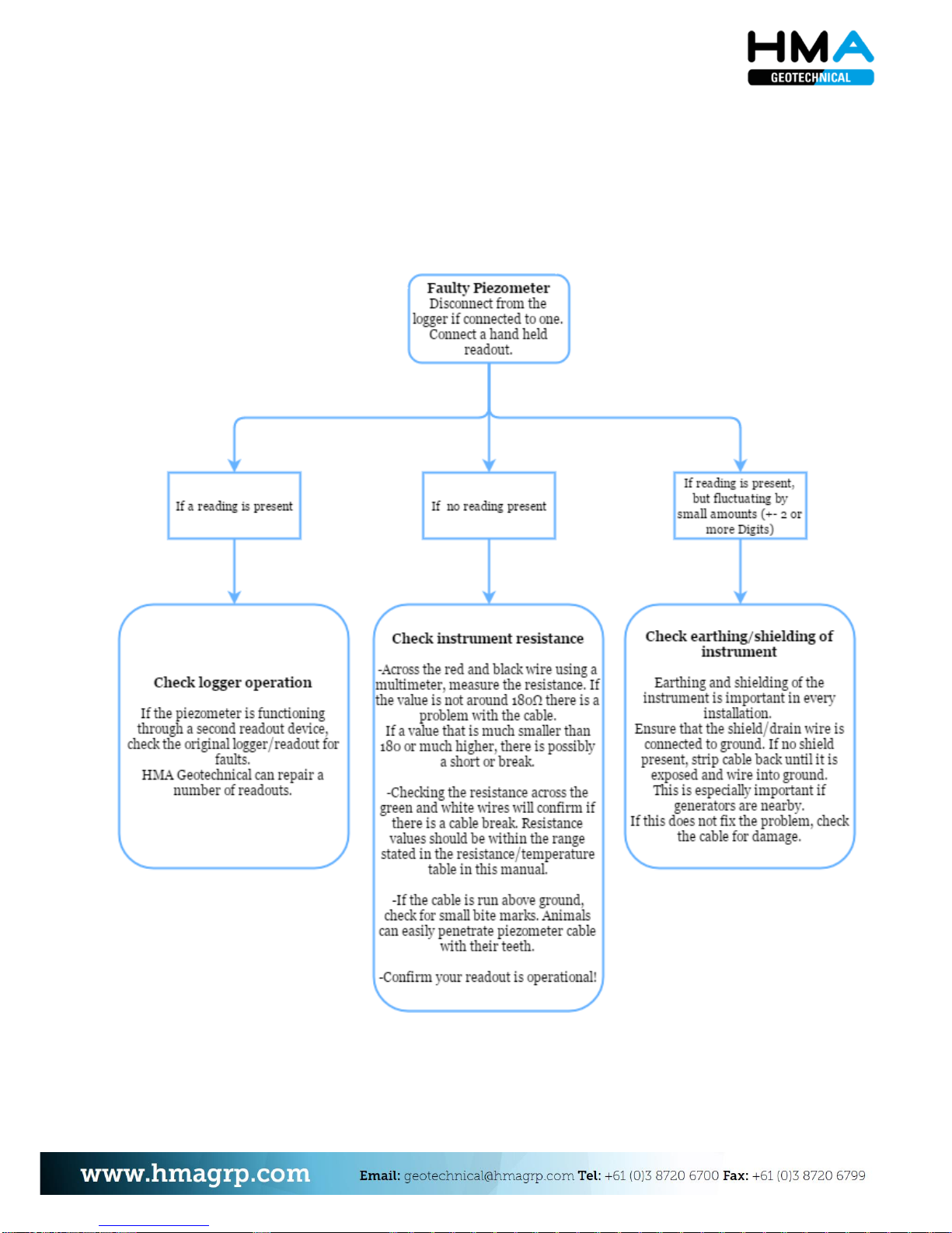
To ensure that the vibrating wire piezometers are functioning properly it is advised that the
instrument be checked periodically. As the transducers are sealed they cannot be opened for
inspection, hence for inaccurate readings the flow chart below should be employed.
Figure 4. Piezometer troubleshooting matrix
Page 14

Page 14 of 19
7. Field Installation Records Sheet
To assist with installations in the field, HMA Geotechnical provide a standard installation record
sheet that allows any field operator to quickly record key data to be used by monitoring engineers
at a later date.
An example is provided below, please contact HMA Geotechnical for a higher resolution copy.
Page 15

Page 15 of 19
8. Standard Temperature vs Resistance Values
Ohms
Temp
o
C
Ohms
Temp
o
C
Ohms
Temp
o
C
Ohms
Temp
o
C
53100
-30
4105
18
13390
-6 1475
42
49910
-29
3922
19
12700
-5 1418
43
46940
-28
3748
20
12050
-4 1363
44
44160
-27
3583
21
11440
-3 1310
45
41560
-26
3426
22
10860
-2 1260
46
39130
-25
3277
23
10310
-1 1212
47
36860
-24
3135
24
9796
0 1167
48
34730
-23
3000
25
9310
1 1123
49
32740
-22
2872
26
8851
2 1081
50
30870
-21
2750
27
8417
3 1040
51
29130
-20
2633
28
8006
4 1002
52
27490
-19
2523
29
7618
5 965
53
25950
-18
2417
30
7252
6 929.6
54
24510
-17
2317
31
6905
7 895.8
55
23160
-16
2221
32
6576
8 863.3
56
21890
-15
2130
33
6265
9 832.2
57
20700
-14
2042
34
5971
10
802.3
58
19580
-13
1959
35
5692
11
773.7
59
18520
-12
1880
36
5427
12
746.3
60
17530
-11
1805
37
5177
13
719.9
61
16600
-10
1733
38
4939
14
684.7
62
15720
-9
1664
39
4714
15
670.4
63
14900
-8
1598
40
4500
16
647.1
64
14120
-7
1535
41
4297
17
624.7
65
Page 16

Page 16 of 19
9. Definitions
Factory Reading
The reading taken at the factory during calibration and shown on the calibration sheet.
Site Test Reading
The reading taken on receipt of the equipment to prove its functionality after shipping.
Zero Reading
The reading taken during the installation and used for all subsequent calculations. This is the most
important reading the installer must take during a field install.
Pressure Coefficient
The pressure factor obtained during factory calibration of the instrument and shown on the
calibration sheet. This is a calibrated value that determines the amount of pressure (usually in
kilopascals) per digit reading. Found on the calibration sheet, calculations cannot be performed
without this value.
Temperature Coefficient
The temperature factor obtained during factory calibration of the instrument and shown on the
calibration sheet. This is a calibrated value that determines the effect of temperature on the
Vibrating Wire Piezometer digits reading.
Page 17
Page 17 of 19
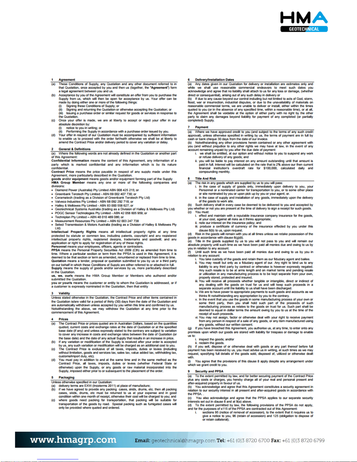
10. HMA Group Conditions of Supply
Accurate as of 14th July 2015. Subject to change. An up to date copy can be viewed at hmagrp.com.
Page 18
Page 18 of 19
Page 19

Page 19 of 19
 Loading...