

Page 1

Magnetic Field Sensors
KMY 20 M
Function principle
Magnetoresistive materials can change their resistivity in an external magnetic field. The
variation of the resistivity is determined by the rotation of magnetisation with respect to the
direction of the current flow. Permalloy (Ni81Fe19) is commercially used as
magnetoresistive material. The relative change of resistivity is 2-3 % for this material. The
high sensitive and small size magnetoresistive sensor consists of the chip 174B coated
with thin film permalloy stripes. These stripes form a Wheatstone bridge, whose output
voltage is proportional to the magnetic field component Hy.
Characteristic
The bridge imbalance is a value for the magnetic field component Hy in the plane of the
chip. It is of advantage to apply an auxiliary field Hx = 3 kA/m which avoids flipping of the
magnetisation of the stripes caused by disturbing magnetic fields. A perpendicular field H
is necessary to stabilize sensor operation. This can be done by using a small permanent
magnet. Magnetic fields vertical to the chip surface have no influence on the output
voltage.
Special feature
In contrast to KMY 20 S, sensor KMY 20 M features a permanent magnet integrated in the
housing. The compact sensor is ready to use. No external auxillary fields are required for
safe operation in a disturbing field up to 30 kA/m.
x
Sensors in thin film technology
HL-Planartechnik GmbH
Hauert 13, D - 44 227 Dortmund, Tel.: +49 (0) 231/97400, Fax.: +49 (0) 231/974020
Internet: http://www.hlplanar.com E-Mail: service@hlplanar.de
Page 2
A
Magnetic Field Sensors
Technical data
Absolute maximum ratings
Parameter Symbol Unit Value
Supply voltage VB V 12
Total power dissipation Pto mW 120
Operating temperature range T
Storage temperature range T
Disturbing field Hd kA/m
°C -40 ... + 125
amb
°C -65 ... +150
stg
≤
30
Electrical characteristics (T
amb
= 25°C)
pplications
- detection of weak magnetic fields,
e.g. earth magnetic field
- contactless mechanical switch
- displacement measurement with
high resolution
- revolution speed detection
on ferromagnetic gear wheels
- contactless angle measurement
- galvanically seperated current
measurement
Parameter Symbol Unit Value
Bridge resistance RB kOhm 1.4 .. 2.2
Open circuit sensitivity SV (mV/V)/(kA/m)
Output voltage range
Hysteresis of output voltage V
Offset voltage V
Permanent auxiliary field Hx kA/m
∆
VO /VB
O H /VB
OFF /VB
µV/V
mV/V
mV/V
Temperature coefficients ( - 25 °C < T
amb
5.5
±
1.5
18.0 ± 4.0
≤
50
≤ ±
1.5
1.5
±
0.4
< 125 °C)
-4 -3 -2 -1 1 2 3 4
of
Parameter Symbol Unit Value
Bridge resistance T
Open circuit sensitivity
Offset voltage T
Difference of offset voltage
for sensor pair
= const) T
(V
B
= const) T
(I
B
%/K
CBR
%/K
CSV
%/K
CSI
(µV/V)/K
COFF
∆
T
COFF
(µV/V)/K
0.30 ± 0.05
-0.25
±
0.05
0.05
±
0.05
≤ ±
3
≤ ±
0.5
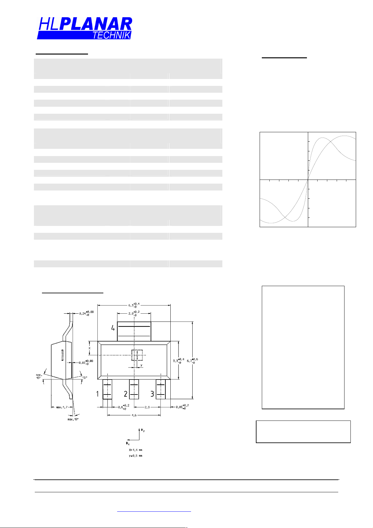
Hausing KMY 20: SOT-223-S
Output voltage versus field component Hy
for different stabilizing magnetic fields H
2 KMY 20 M
We also offer selected
pairs of KMY 20 M.
These pairs have a
similar temperature
characteristic of the
voltage offset and are
well suited for differential
measuring techniques.
The temperature drift of
the magnetoresistive
sensor is strongly
reduced by applying this
technique.
KMY 20 M
U [mV/V]
0
8
6
4
2
-2
-4
-6
-8
H = 1 kA/m
H = 3 kA/m
x
x
H [kA/m]
y
x
SOT-223-S
1: +V0 2: -V0 V0: Ausgangsspannung
metrische Dimensionen
Sensors in thin film technology
3: +VΒ 4: -VB VB: Betriebsspannung
HL-Planartechnik GmbH
Hauert 13, D - 44 227 Dortmund, Tel.: +49 (0) 231/97400, Fax.: +49 (0) 231/974020
Internet: http://www.hlplanar.com E-Mail: service@hlplanar.de
7.12.01
 Loading...