


Thermo Shakers and BlockThermostats
with Smart Control
MKR 13 – MKR 23 – MHR 13 – MHR 23–
MHL 23 – TK 23
Operating Manual
Bedienungsanleitung

2
Content
1. Basic Data ................................................................................................ 4
Safety .............................................................................................................4
Warranty ........................................................................................................5
Disclaimer of warranty ...................................................................................5
Important information ...................................................................................5
Environmental conditions……………………………………………………….………………….6
Temperature accuracy ...................................................................................6
2. First Steps ................................................................................................ 7
Setup ..............................................................................................................7
3. Operation ................................................................................................ 7
Parameter setting ..........................................................................................7
Programming function .................................................................................13
4. Assembly of Accessories ...................................................................... 19
Anti-Condensation Plate BA 24 / 96 .............................................................19
Data transfer ................................................................................................20
5. Troubleshooting ................................................................................... 23
6. Maintenance ......................................................................................... 24
Cleaning ........................................................................................................24
Service ..........................................................................................................25
7. Technical data ....................................................................................... 26
8. Article description blocks & accessories ............................................ 30
9. Explanations……………………………………….…………………………………………………32

3
Inhaltsverzeichnis
1. Basisdaten ................................................................................. 33
Sicherheit ............................................................................................ 33
Gewährleistung und Garantie ............................................................... 34
Haftungsausschluss .............................................................................. 34
Wichtige Hinweise ............................................................................... 34
Umgebungsbedingungen ...................................................................... 35
Temperaturgenauigkeit ........................................................................ 35
2.
Erste Schritte ............................................................................. 36
Inbetriebnahme ................................................................................... 36
3.
Bedienung ................................................................................. 37
Einstellung Parameter .......................................................................... 37
Programmierungsfunktion .................................................................... 43
4.
Montage von Zubehörteilen ....................................................... 50
Antikondensplatte BA 24 / 96 ............................................................... 50
Datentransfer ...................................................................................... 51
5.
Problembehebung ..................................................................... 54
6.
Instandhaltung .......................................................................... 55
Reinigung ............................................................................................ 55
Service ................................................................................................ 56
7.
Technische Daten....................................................................... 57
8.
Artikelbezeichnung Blöcke & Zubehör ........................................ 61
9.
Erläuterungen ............................................................................ 63
Basic Data
The HLC by DITABIS Thermo Shakers and Block Thermostats are used for tempering and mixing of solutions in closed reaction tubes and plates. Please pay
attention that the target temperature of the samples should not exceed the
boiling point of the solution, which should be heated. Please consider this
when setting the target temperature via the software of the Thermo Shaker
or Block Thermostat. If there are any uncertainties regarding the liquids,
which should be heated or cooled, please contact DITABIS. The HLC by DITABIS devices are meant for indoor usage only. Please use only HLC by DITABIS
accessories or accessories recommended by HLC by DITABIS.
Safety
The systems comply with the standards and directives mentioned in the applicable CE declaration.
Please take note of the following safety measures:
Do only connect the system to an earthed mains power
socket of 230 V, 50 Hz.
Do not place hot blocks on inflammable or not heat-resistant
surfaces.
Make sure to only use containers in the block which are
suitable for the desired temperature range.
If liquid gets into the system, immediately pull out the plug
and contact our service department to ensure complete
safety.
Please do not touch or transport hot systems.
Contact with highly flammable fluids must be avoided.
The ventilation of the device must not be blocked. To ensure
the proper ventilation at all times please consider a minimum distance of 10 centimetres on each side of the device.
Damaged mains cable should only be replaced with equal
ones.
4

5
Warranty
All functions of the systems have been tested thoroughly. After that, the
system and the accessories were packed carefully in perfect condition. If,
however, any damages or defects are detected during installation or
setup, please contact your local dealer or the DITABIS service department.
The DITABIS contact information can be found at www.ditabis.de (see also
our Terms and Conditions at www.ditabis.com). If used under normal laboratory conditions according to the Operating Manual, DITABIS grants a warranty
of one year, starting with the day of shipment.
Disclaimer of warranty
In case of unspecified use of the device, the manufacturer assumes no responsibility.
Important information
This manual complies with the standards and directives mentioned in the EN
DIN 61010-1 Norm. IQ, OQ and PQ documents are available on request.
The systems are provided with a high-precision self-optimising
temperature controller. Due to the self-optimisation it might occur that the set temperature is exceeded in individual cases.
Please note, that by heating your samples dangerous gases may
be emitted. In this case, the device must be used with an extractor hood.
If the ThermoMixers are operated with a high shaking frequency,
the vibrations of the system might transmit to the underground.
Please do consider this when placing the system.
i

6
Contact with highly flammable liquids must be avoided. The exchangeable block may be hot.
The ventilation of the device must not be blocked. To ensure the
proper ventilation at all times please consider a minimum
distance of 10 centimetres on each side of the device.
Environmental conditions
The ideal area of operation of the devices is achieved at 80% relative air
humidity at most and lays between +3°C - +50°C ambient air temperature.
This range should not be underrun or exceeded.
Temperature accuracy
Every HLC by DITABIS system is calibrated with a gauged high-precision temperature measuring device to temperature accuracy and reproducibility. This
calibration is performed at a room temperature of +20,0°C at 10 different
temperature calibration points and oil as a reference liquid. HLC by DITABIS
reaches a very high accuracy by measuring the block temperature directly
inside the block. It can, however, not be avoided that the room temperature
affects the sample temperature in case of a large temperature difference
between room and block temperature. The anti-condensation plate reduces
this effect. We recommend using the anti-condensate plate BA 24 / BA 96 or
the tempering tub BT 01 / BT 02. When setting a process time, please note
that the sample temperature is always reached a little later than the displayed block temperature.

7
First Steps
Setup
Plug the mains cable in the IEC socket on the back of the system and connect
it with the mains power 230 V, 50 Hz via a Schuko socket. Please make sure
that you are using earthed mains power sockets.
Changeable blocks
At delivery, the changeable blocks are packed separately. Place the blocks on
the tempering plates and take care of the proper alignment of the central
threaded bolt and the two small corner bolts ensuring that the block lays
accurately on the tempering plate. Then attach the block with the enclosed
socket screw tightly at the bottom of the tempering plate to get the block
fixed for shaking and to obtain even better temperature accuracy. Check the
tight attachment of the block by pulling it up
Never start the process without the block being tightly attached. Do always
use two blocks for two-block systems, even if only one of them is used. This
ensures safety as well as a smooth shaking operation.
Switch on the system with the mains switch on the back of the system. The
start menu will be displayed. The green LED turns on, on the right sight of the
touch panel, as soon as a process is running.
Operation
Parameter setting
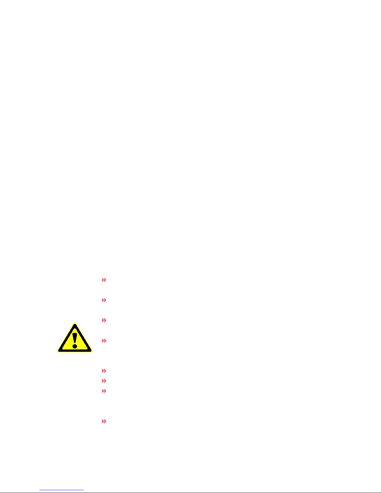
Start menu
This menu is displayed after the power is
switched on, after abortion or after the normal completion of a process. The last set
values are retained even after the switch-off
of the system.
8
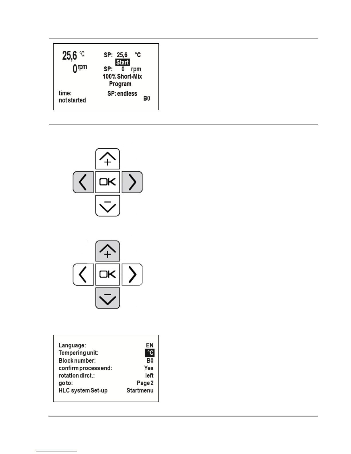
Setup menu
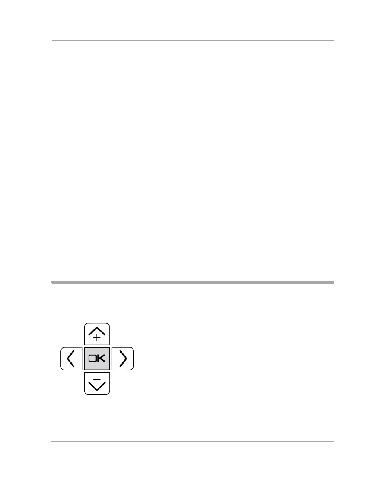
Push the left and right arrow keys at the
same time, then the setup menu is displayed.
With + and – the values can be selected for
setting.
The selected box flashes, with ok it will be
permanently set for changing.
With the keys + and –, the input or the values
can be changed. If an input is confirmed with
ok, the box will highlighted flashing again.
With confirming the button Start menu, the
start menu is displayed again.
The following values can be adapted:
Page 1:
Language: English, German, French, Spanish
Tempering unit: °C or °F
Block number (10-point calibration)
Confirm end:
Yes: at the process end, a signal is audible
until the ok key is pushed. Until then, the
process runs with the previous data.
No: the process ends without confirmation.
9
Rotation direction: right, left
Page 2:
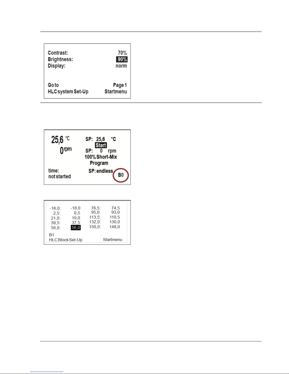
Contrast: Mentioned in %
Brightness: Mentioned in %
Display colour: Normal - inverse
10-point-calibration
By default the standard
calibration begins
with the block number “B0”. 10 temperature
bases are underlying
this calibration. The
calibration is optimized for all DITABIS standard blocks. If you are using customized blocks
you will be able to do individual calibrations
in addition.
For the calibration you need a
gauged high-precision temperature measuring device.
Select block number in the set up menu and
confirm with ok. You are now able to calibrate and save different individual calibrations, from standard block B1 up to 4. Therefore please select B1 to B4. Confirm again
with ok. Now you will get to the calibration
menu. In the first and third column you can
see the temperature base. In the second and
fourth column you can see the variable set
values.
By pushing the + and – keys the entries and
values can be changed. The selected field is
blinking; by pushing ok the field is selected
for changing.
Example:
You have adjusted the device for 95,0°C in the
start menu and are measuring only 85,0°C
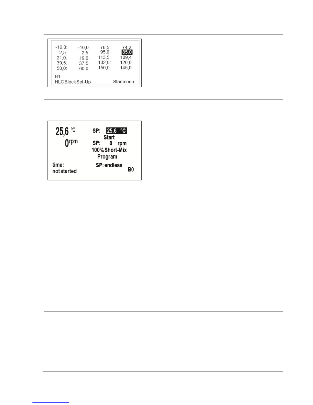
10
with a calibrated thermometer inside your
sample. Now you have to change the temperature set value in column four about 10°C.
By doing so you can calibrate every single
base individually.
Temperature set value
Navigate with + and – to the temperature
input box and confirm with ok. The individual
numbers can be selected with arrow left and
right, their value can be changed with +
and -. The input is confirmed with ok and the
cursor automatically jumps to the Start button.
A set value change can also be made in the
same way during a running process. After
confirming the input with ok, the new set
value is effective immediately. For the hundreds, the following values can be selected:
0 for temperatures up to +99,9°C
1 for temperatures from +100,0°C
- for temperatures below 0,0°C
Important information
For cooling systems, the minimum temperature may not be smaller than the difference
from room temperature mentioned below.
MKR 13 / TK 23: 16°C below r.t.
MKR 23: 11°C below r.t.
Mix set value
Navigate with + and – to the shaking frequency input box and confirm with ok. The
individual numbers can be selected with
arrow left and right, its value can be changed
with + and –.
The input is confirmed with ok and the cursor
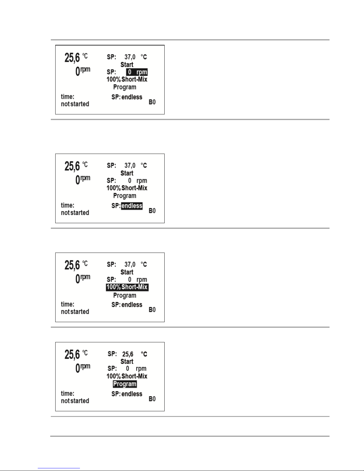
11
automatically jumps to the button
Start
.
The 1. Digit number cannot be selected and
changed. A set value change can also be
made in the same way during a running process. After confirming the input with ok, the
new set value is effective immediately.
Duration of the process (time
setting)
Navigate with + and – to the time input box
and confirm with ok. The individual numbers
can be selected with arrow left and right, its
value can be changed with + and –.
The input is confirmed with ok and the cursor
automatically jumps to the button Start.
For an endless process, select 00:00.
100% Short-Mix (vortexing)
Navigate with + and – to the button 100%
Short-Mix and confirm with ok. The system
shakes with maximum mixing speed regardless of a process is started or not.
During the whole shaking process ok must be
pushed continuously..
Select program mode
Navigate with + and – to the button
Program and confirm with ok. For detailed
information on programming see page 10.
12
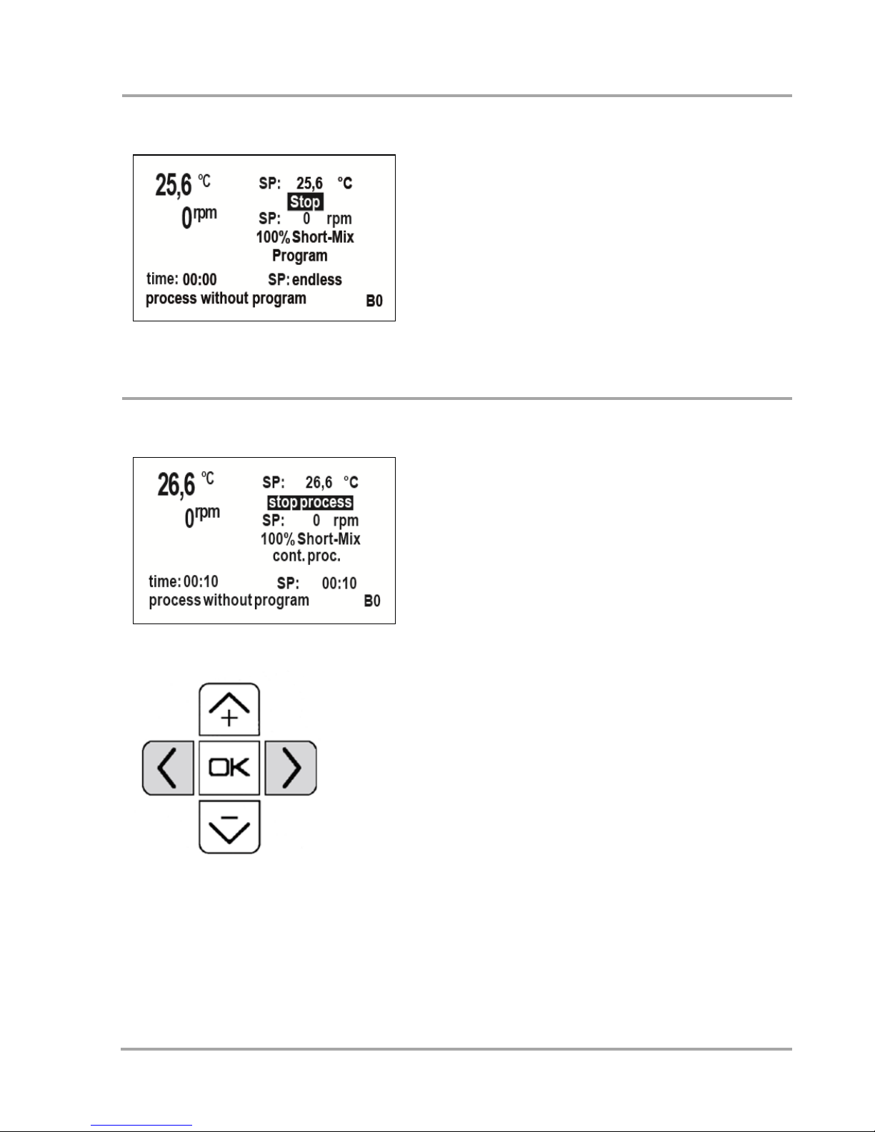
Process without time setting
Only set a set temperature and a set shaking
frequency but set the time on continuous
00:00. Now, the process time is displayed
continuously. It only starts to run if the temperature set value is reached. A set value
change can also be made as described above
during a running process. Changes are retained also after the completion of the process and are displayed in the start menu as
current set values. For terminating the pro-
cess, push Stop.
Process with time setting
If a process time is set, the remaining time is
displayed in the menu. The time only starts to
run if the temperature set value is reached.
This does also apply for subsequent temperature changes. A set value change can also be
made as described above during a running
process.
The process ends without a signal or continuous with a signal until it is terminated
manually. The relevant modus can be set in
the setup menu.
For changes during the process
If set value changes have been made, you can
select to save these changes and to have
them displayed in the start menu as new set
values.
Stopping the process before the expiration
of the time
If the process is stopped or changed before
the expiration of the time, you can select
whether the process really should be termi-
13
nated or if it should continue. Depending on
the selection, the start menu or the selection
to continue the process from the stop (time
runs from stop) or to make a restart (time
runs from zero) is displayed.
Process end
Setting in setup:
Confirm end: Yes
If a process time is preset, the expiration of
the time is indicated by a flashing LED and a
signal, the process continues. You can terminate the process with ok.
Confirm end: No
If a process time is preset, only the information that the process is completed will be
displayed after the expiration of the time. The
device turns off automatically.
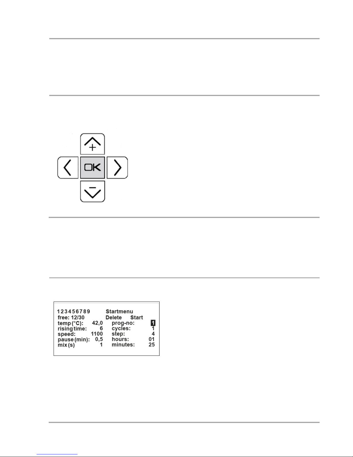
Programming function
Program menu
Navigate with + and – to the button Pro-
grams and confirm with ok. A total of 30
different program steps can be preset,
distributed on max. 9 different programs.
Confirm the highlighted flashing program
number if you want to change it. Confirm
the progr. no. with ok. With + and – , the
program numbers 1-9 can be selected.
If you want to edit the displayed program,
select the different adjustable parameters
with + and –. For editing, confirm with ok
and change the value. For final confirma-
tion confirm with ok again.
14
Setting of the individual paramater
By selecting "Programs" in the start menu, you will have a total number of 30
different (recurrent) program steps available. These can be selected in up to 9 different programs. You have the choice of f. ex. either 9 programs with 3 program
runnings each or f. ex. 1 program with 30 program runnings. For normal operation
the choice will be somewhere in between.
"prog-no." is blinking and shows 1 as standard. By pressing ok any program num-
ber. between 1 and 9 can be selected using buttons + and –. Confirm your entry by
pressing ok and the next field "cycles" will be blinking.
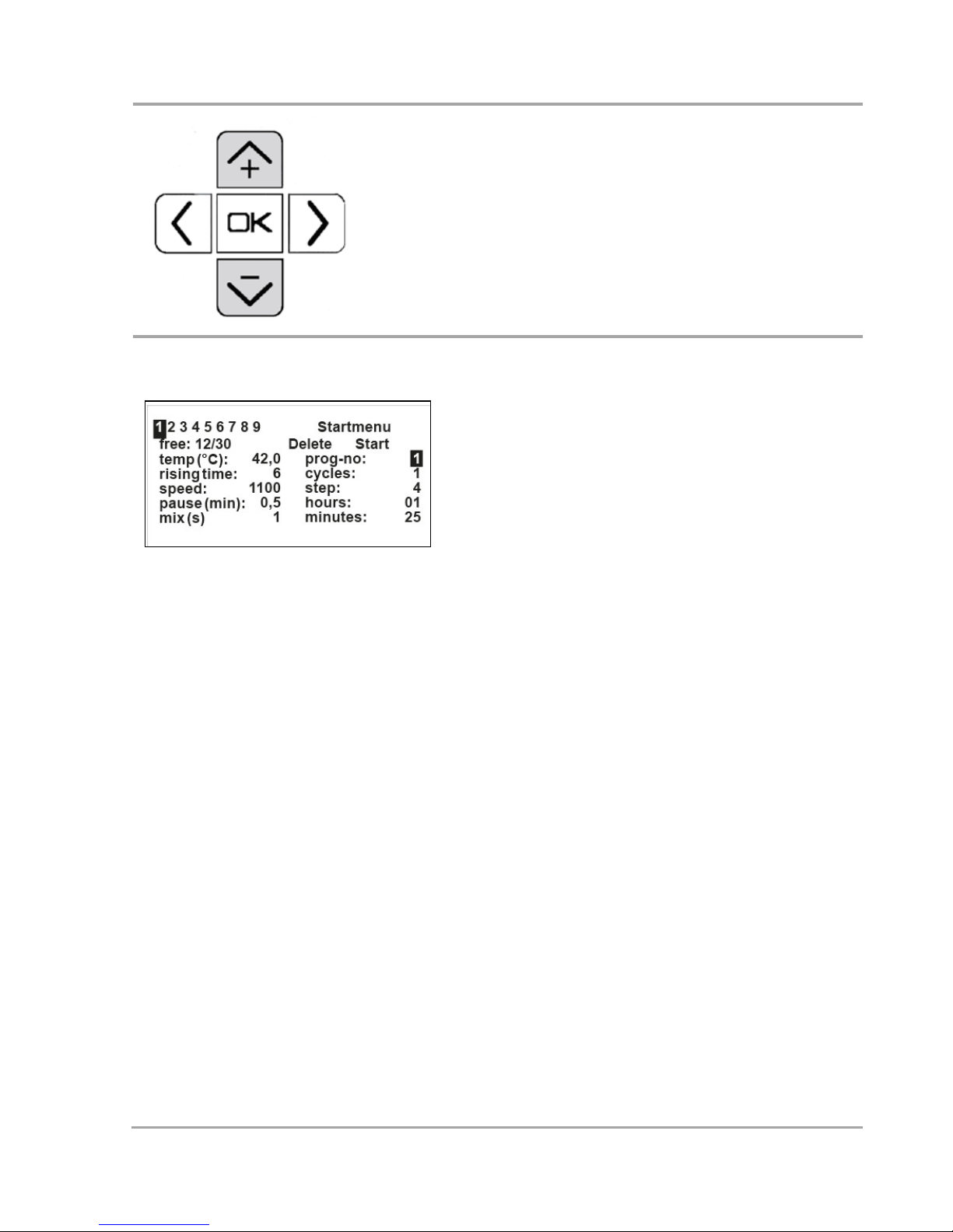
Cycles = Number of repetitions of the program, selection 1-9 possible without
having to confirm "Start" again.
If no changes are to be made, select the next field by using the - (down) button.
By pressing ok you can change the number of cycles from 1 to 9 using the + and –
buttons. Confirm your entry by pressing ok and the next field "step"
will be blinking.
Step = Section within a program. Selection 1-9 possible.
If no changes are to be made, select the next field by using the – (down) button.

15
For changing the program step displayed, press ok. A value between 1 and 30 can
be selected using buttons + and –. Confirm your entry by pressing ok and the next
field "hours" will be blinking. If in the field "minutes" no entries are to be made,
select the next field by using the – (down) button.
Hours = Duration of the section in hours.
If no changes at "hours" are to be made, select the next field by using the – (down)
button. For any changes press ok; the ones column is highlighted and can be
changed with buttons + and –. For changing the tens column use button for mark-
ing and + and – for changing. Confirm your entry by pressing ok and the next field
"minutes" will be blinking.
Minutes = Duration of the section in minutes.
For entries press ok; the tens column is highlighted and can be changed by using
buttons + and –. For changing the ones column use button for marking and + and –
for changing. Confirm your entry by pressing ok and the next field "temp °C" will be
blinking.
Time "endless"
If a program step (normally the last one) shall be running without a time setting
until the program will be completed manually, i.e. endless, the hours and minutes
must be set to 00.
Temperature = Set temperature of the section.
The temperature set value is 37°C as standard. If no changes are to be made, select
the next field by using the – (down) button. To change this value press ok. Every
single digit can be changed. The cursor is placed at the tens column of the set value.
This value can be changed with buttons + and –. To change another digit in this
data field, it must be marked by buttons < and >. The highlighted value will be
changed with button + or –. After setting the value it must be confirmed with ok;
the field "rising time" will be blinking.
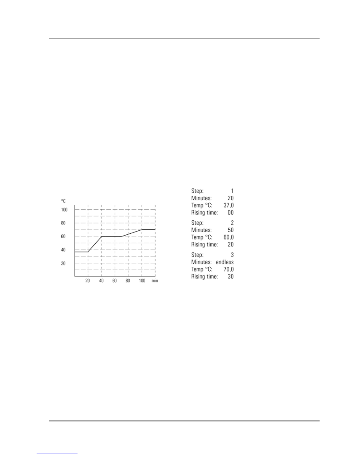
Rising time = Time setting for tempering the sample to set temperature. This setting is only required if the sample is to be tempered slower than in presttings of the
device. If the sample is to be tempered as fast as possible, set the value to 0.
With "rising time" the heating or cooling speed compared with the normal speed
16
can be reduced. You have the possibility to determine a certain period (= rising
time; with a max. of 99 minutes to choose) in which a set temperature shall be
reached in the actual program step, if a slower than normal tempering is desired.
As shown in the illustration beside, a temperature of 60,0°C in step 2 shall be
reached within 20 minutes, starting from a temperature of 37,0°C in step 1. If no
changes are to be made in "rising time" (fastest possible heating or cooling time),
select the next field by using the – (down) button. For changing the standard value
0 press ok; the ones column is highlighted and can be changed with buttons
+ and –. For changing the tens comlumn use button for marking and + and – for
changing. Confirm your entry by pressing ok and the next field "speed" will be blinking.
Example of a temperature program:
Rotational speed = Shaking frequency with which the blocks are shaken.
The last number (1. digit) can not be selected and changed.
For "speed" 0 is set as standard. If no changes are to be made (tempering without
shaking), select the next field by using the – (down) button. To change this value
press ok; every single digit can be changed. The cursor is placed at the hundreds
column of the set value. This value can be changed with buttons + and –. To change
another digit in this data field, it must be marked by buttons < and >. The highlighted value will be changed with button + or –. The last digit (ones column) cannot be
chosen and changed. After setting the value it must be confirmed with ok; the
field "pause" is blinking.
17
Interval shaking = Interval shaking is an alternative when the probe shall not
be subject to permanent shaking. A resting time of up to 9.9 minutes can be set in
"pause". The following short shaking time of up to 9 seconds is set in "mix sec".
This is a reasonable choice for the last program running of a complete program with
time setting "endless" during off working hours.
Pause [min] = Resting time of up to 9.9 minutes. If no intervals are to be set, enter
the value 0.0 here.
Duration of pause is 0.0 as standard. If no changes are to be made, select the next
field "step" by using the – (down) button. To change this value press ok; the ones
column is highlighted and can be changed by using buttons + and –. For changing
the 1/10 digit press button >; the digit is highlighted and can be changed with buttons + and –. Confirm your entry by pressing ok and the next field "mix sec" will be
blinking.
Mix [s] = Short shaking time up to 9 seconds after resting time.
For "mix sec" 1 is set as standard. If no changes are to be made, select the next field
"step" by using the – (down) button. For changing the shaking time press ok and
change time by using buttons + and –. Confirm your entry by pressing ok and the
next field "step" will be blinking.
Entry of further program steps
If another program step shall be added to
a chosen program, press ok at the blinking field "step" and increase the number
of the last program step by 1. Further
entries as already described.
To change the program data entry
To change the chosen program, enter the
program step number to be changed.
Select the field to be changed by using
buttons + and – . Press ok for changing.
Changes are made as already described
18
and must be confirmed with ok. Select a
corresponding field by using buttons +
and – or < / >.
Termination of program data entry
To complete a chosen program, mark
either "Start" (to start the program immediately) - screen 6 will appear, or
"Startmenu" (to save the program only) screen 1 will appear. You can also select
"prog-no." (for entry of another program). When "Delete" is selected, the
complete program with all program steps
as displayed is deleted
Starting a program
Select the relevant prog. no. and confirm
the Start button in the program menu.
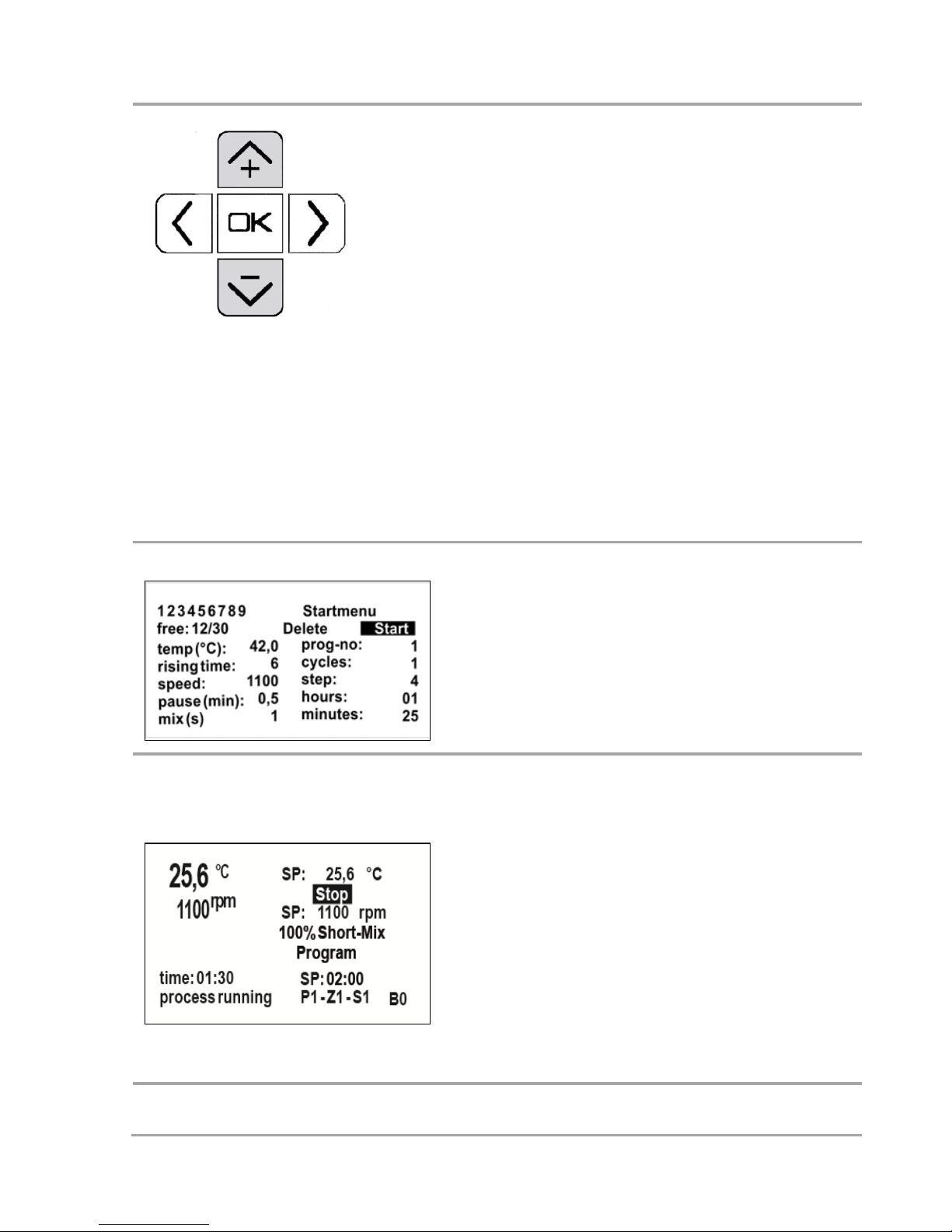
Changing parameters during the
program process
Change of temperature and rotational
speed as well as performing a Short-Mix
are possible during a running program.
The set time is the time of the running
step, the remaining time is the time of
the complete process. In the lower right
part of the display, program no., cycle and
step are indicated.
19
Assembly of accessories
Anti-Condensation Plate BA 24 / 96
The anti-condensation plate BA 96 (800013000) is placed on the attached
block, no assembly steps are required. For using the anti-condensation plate
BA 24 (800012900), remove the socket screw in the block with the enclosed
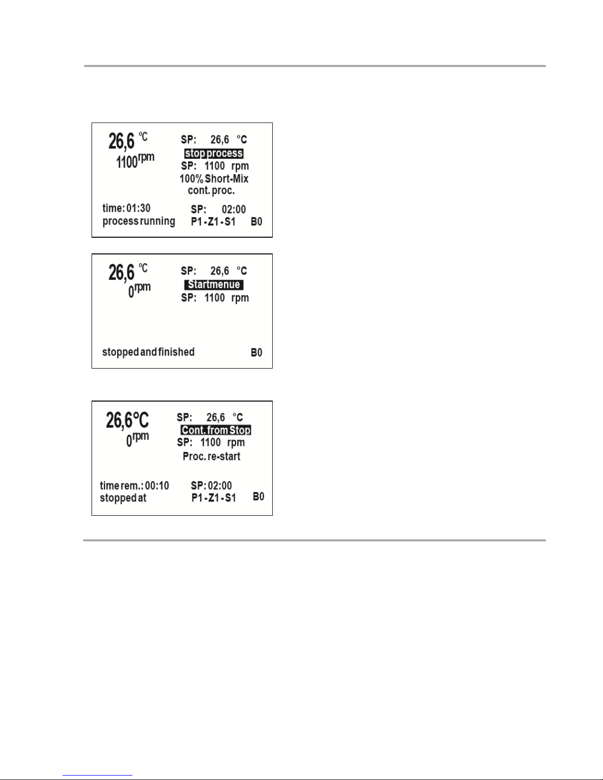
Termination/ interruption of the
program:
If you push Stop, the options stop
process and continue process are dis-
played.
If you select stop process, the Start menu
or Save changes is displayed if parame-
ters have been changed during the process.
If you select Continue with process the
selection Continue from stop or
Process Restart is displayed (program
starts from cycle 1, step 1).

20
screwdriver. Screw the enclosed threaded pin with isolation knob into the
anti-condensation plate. Place the anti-condensation plate on the block and
screw the threaded pin in deeper so that it takes hold of the bolt of the system and with that tightly attaches block and anti-condensation to the system.
Data transfer
A USB 1.1. interface for the communication with a PC is provided as a standard. Connect the system via the USB-port on the left side with a USB-cable to
your PC. If this is not available at your computer, install the suitable USBdriver. You will find it under www.ftdichip.com/Drivers/VCP.htm. These USBdrivers generate a new virtual COM-interface in your PC. The chip in the Smart
Control is called FT232B.
Access process data via USB
Start a terminal program (e.g. Hyper terminal) on your PC. This program you
will find under Windows in "Programs" / "Accessories" / "Communication".
The window "Hyper Terminal" is opened. Proceed systematically, please note
that for the connection setting for "Bits per second" 115200 is selected. Select
at "Transfer": "Record Text", enter the location and define the file name as
.txt Start the Hyper Terminal and the process. Every minute, the following
data are recorded in text format and separated by comma in the form shown
on the right.
Since the data are separated by commas, you can easily create an Excel file
and generate one or more curves from that. If you open the text file you selected for saving, you can see the complete process.

21
START
Setpoints
xx:xx,+37.0,0200,01,01,01,00
:01,00,9,0.2
time
hh:mm,tmp,rpm,prg,cycle,st
ep,steptime hh:mm,rem.
risetime_m,mix_s,pause_m
00:00,+26.9,0000,01,01,01,0
0:00,00,9,0.2
00:01,+33.7,0220,01,01,01,0
0:00,00,9,0.2
00:02,+36.7,0000,01,01,01,0
0:00,00,9,0.2
00:03,+36.9,0000,01,01,01,0
0:00,00,9,0.2
START
Setpoints
xx:xx,+70.0,0300,01,01,02,00
:12,10,9,0.1
time
hh:mm,tmp,rpm,prg,cycle,st
ep,steptime hh:mm,rem.
risetime_m,mix_s,pause_m
00:04,+36.9,0000,01,01,02,0
0:00,10,9,0.1
00:05,+39.1,0000,01,01,02,0
0:01,09,9,0.1
00:06,+42.1,0000,01,01,02,0
0:02,08,9,0.1
00:07,+45.2,0300,01,01,02,0
0:03,07,9,0.100:08,+48.4,030
0,01,01,02,00:04,06,9,0.1
00:09,+51.7,0000,01,01,02,0
0:05,05,9,0.1
00:10,+54.9,0000,01,01,02,0
0:06,04,9,0.1
00:11,+58.2,0300,01,01,02,0
0:07,03,9,0.1
00:12,+61.5,0300,01,01,02,00:08,02,9,0.1
00:13,+64.7,0000,01,01,02,00:09,01,9,0.1
STOP

22
Enter process data via USB
For the process control of a HLC system with Smart Control via a USBinterface, four commands are possible and required:
Start
Starts a process without program with the parameters indicated on the display. Time settings, if applicable, are deleted and overwritten by continuous
since time settings must be programmed on the computer.
Stop
Stops all processes and returns to the start menu, running programs / processes are aborted.
t=0370
Changes the set temperature to a new value.
The temperature must always be entered with four digits.
t=0370 sets 37.0°C, t=0050 sets 5.0°C, t=-060 sets -6.0°C.
t= is the identification for a temperature value. The associated numerical
value reflects the value in tenth of a degree.
The first digit after the = can be a 0, a 1 or a hyphen. Invalid temperature
values are - like for the input at the system - replaced by the next valid value.
r=020
Changes the set rotational speed to a new value.
The rotational speed must always be entered with three digits.
r=120 sets 1,200 1/min, r=045 sets 450 1/min.
r= is the identification for a rotational speed value. The associated numerical
value reflects the value in 10 1/min.
Invalid rotational speed values are - like for the input at the system - replaced
by the next valid value.

23
r=000
Stops the rotational speed, e.g. if shaking should be stopped but tempering be
continued.
Other inputs like e.g. r=0 are interpreted as rotational speed and cause the
motor to rotate with the minimum rotational speed.
Every command must be confirmed with "CR"
In case of unknown commands and/or in case of spelling errors, nothing is
done. The inputs in the setup menu like colour, contrast and brightness of the
display, language, rotation direction etc. can only be done at the operating
panel of the system itself.
Troubleshooting
The display remains blank
Please check if the mains switch on the back side is switched on.
If it is switched on but voltage is present at the socket, check the micro-fuse
and replace if required. (IEC 127-2/III, 250 V, 2 A time-lag).
This fuse - and a spare fuse - are located in the IEC-bushing (in which the connection cable is plugged). The fuse box can be pulled out with a screwdriver.
The system does not cool, heat or shake as set
Check whether the display indicates the correct system type name at poweron. If not, please contact your local dealer or the HLC by DITABIS service department.
There are excessive temperature fluctuations
Check the seat of the changeable block by pulling it up. If it is too loose or if
the block exhibits roughness, e.g. contamination, the heat / coolness is not
transferred correctly.

24
Information on the capacitive touch display
The touch display reacts on finger pressure, even when wearing thin latex
gloves, but not on stylos.
Due to its glass surface, the front panel is insensitive to dirt, chemicals and
mechanical damage. Please avoid scratches in the coating since they can
cause malfunctions. Please take note of the following cleaning instructions.
Maintenance
Cleaning
Regularly clean the housing and the changeable blocks of the
Thermo Shakers and BlockThermostates.
Precautions for avoiding electric shocks
Electronic devices can cause electric shocks in case of an operat-
ing error. Never try to repair electric parts. Never open the housing.
• Switch off the system and disconnect it from the power
supply before starting with cleaning or disinfection
works.
• Never let get liquids inside the housing (ventilations
slit).
• Do not perform spray disinfection.
• Do only connect the system with the power supply if it is
completely dry.
The repair service may only be performed by staff authorized
and trained by the manufacturer. A modification of the system is
not permitted.

25
Caution when handling aggressive chemicals
Do not use aggressive chemicals like e.g. strong and weak bases,
strong acids, formaldehyde, acetone, halogenated hydrocarbons
or phenol for cleaning the system and its accessories.
• In case of contamination with aggressive chemicals,
clean the system with a neutral detergent immediately.
• Use neither corrosive detergents nor aggressive solvents
or abrasive polishing agents.
Cleaning
1. Please disconnect the system from the power supply before you start
cleaning.
2. Please clean all outer parts of the system with a mild detergent and a
lint-free cloth.
3. Please wipe off the detergent with Aqua dest..
4. Please dry all cleaned parts.
Disinfection
1. Please disconnect the system from the power supply before you start
disinfecting.
2. Let the system cool down.
3. Please clean the system as described above.
4. Please select a disinfection method compliant to the applicable local
legal regulations and directives.
5. Please wipe off all outer parts of the system with the disinfectant and
a lint-free cloth.
Service
If a technical problem arises, please contact your local dealer or the DITABIS
service department. The DITABIS contact information can be found at
www.ditabis.com. If required, the system will be returned for repair – please
take note of our service guidelines, which can be found at www.ditabis.com as
well.

26
Decontamination before shipment
If you send the system to the authorised technical service for repair or to your
distributor for disposal, decontaminate all parts you want to send. Document
the decontamination in a Decontamination Certificate (incl. serial number)
and include it with the shipment.
Technical data
Technical Data
MKR 13
Temperature-working range
Amb. -16°C to +100°C
Temperature-adjustable range
-10°C to +105°C
Accuracy / resolution
+/- 0.1°C / 0.1°C
Max. heating time
6.0°C / min
Max. cooling time
12.0°C / min
Shaking frequency
200 – 1,500 rpm
Orbit
3 mm round
Dimensions (without block) W x D x H
220 x 330 x 144 mm
Block - capacity
1 changeable block
Weight (without block)
9.0 kg
Power input
130 W
Electr. supply
230 V / 50 Hz
(115 V / 60 Hz available)
Fuse
2AT
Protection class
IP21
Environmental conditions
Ambient air temperature
3° – 50°C
in service (non-condensing)
Relative humidity
max. 80%

27
Technical Data
MKR 23
Temperature-working range
Amb. -11°C to +70°C
Temperature-adjustable range
0°C to +80°C
Accuracy / resolution
+/- 0.3°C / 0.1°C
Max. heating time
3.5°C / min
Max. cooling time
6.5°C / min
Shaking frequency
200 – 1,200 rpm
Orbit
3 mm round
Dimensions (without block) W x D x H
220 x 330 x 144 mm
Block - capacity
2 changeable blocks
Weight (without block)
9.5 kg
Power input
200 W
Electr. supply
230 V / 50 Hz
(115 V / 60 hz available)
Fuse
2AT
Protection class
IP21
Environmental conditions
Ambient air temperature
3° – 50°C
in service (non-condensing)
Relative humidity
max. 80%
Technical Data
MHR 13
Temperature-working range
Amb. +3°C to +130°C
Temperature-adjustable range
0°C to +137°C
Accuracy / resoultion
+/- 0.1°C / 0.1°C
Max. heating time
11.5°C / min
Shaking frequency
200 – 1,500 rpm
Orbit
3 mm round
Dimensions (without block) W x D x H
220 x 330 x 109 mm
Block - capacity
1 changeable block
Weight (without block)
6.5 kg
Power input
200 W

28
Electr. supply
230 V / 50 Hz
(115 V / 60 Hz available)
Fuse
2AT
Protection class
IP21
Environmental conditions
Ambient air temperature
3° – 50°C
in service (non-condensing)
Relative humidity
max. 80%
Technical Data
MHR 23
Temperature-working range
Amb. +3°C to +130°C
Temperature-adjustable range
0°C to +137°C
Accuracy / resolution
+/- 0.1°C / 0.1°C
Max. heating time
9.5°C / min
Shaking frequency
200 – 1,500 rpm
Orbit
3 mm round
Dimensions (without block) W x D x H
220 x 330 x 109 mm
Block - capacity
2 changeable blocks
Weight (without block)
7.0 kg
Power input
350 W
Electr. supply
230 V / 50 Hz
(115 V / 60 Hz available)
Fuse
2AT
Protection class
IP21
Environmental conditions
Ambient air temperature
3° – 50°C
in service (non-condensing)
Relative humidity
max. 80%

29
Technical Data
MHL 23
Temperature-working range
Amb. +3°C to +130°C
Temperature-adjustable range
0°C to +137°C
Accuracy / resolution
+/- 0.1°C / 0.1°C
Max. heating time
9.5°C / min
Shaking frequency
200 – 1,300 rpm
Orbit
3 mm linear
Dimensions (without block) W x D x H
220 x 330 x 109 mm
Block - capacity
2 changeable blocks
Weight (without block)
7.0 kg
Power input
350 W
Electr. supply
230 V / 50 Hz
(115 V / 60 Hz available)
Fuse
2AT
Protection class
IP21
Environmental conditions
Ambient air temperature
3° – 50°C
in service (non-condensing)
Relative humidity
max. 80%
Technical Data
TK 23
Temperature-working range
Amb . -16°C to +90°C
Temperature-adjustable range
-10°C to +105°C
Accuracy / resolution
+/- 0.3°C / 0.1°C
Max. heating time up
4.0°C / min
Max. cooling time
7.0°C / min
Dimensions (without block) W x D x H
220 x 330 x 144 mm
Block - capacity
2 changeable blocks
Weight (without block)
7.5 kg
Power input
130 W
Electr. supply
230 V / 50 Hz
(115 V / 60 Hz available)

30
Article description blocks & accessories
Blocks
Art. No.
Dimensions of the Containers
For
800010800
BM 02 for 96 x 0.2 ml conical & 8-container stripes
micro
800010900
BM 05 for 38 x 0.5 ml conical
test tubes
800011000
BM 15 for 24 x 1.5 ml conical
800011100
BM 20 for 24 x 2.0 ml cylindrical
For sample
800011500
BP 10 for 24 x D=10.3 mm, 46 mm deep, round bottom, lid
tubes
800011600
BP 12 for 24 x D=12 mm, 20 mm deep, flat bottom
800011700
BP 15 for 24 x D=15 mm, 30 mm deep, flat bottom
800011800
BP 16 for 24 x D=16.5 mm, 46 mm deep, round bottom, lid
800014200
BP 17.0 for 24 x D=17 mm, 30 mm deep, flat bottom
800016100
BP 19.2 for 24 x D=18.7 mm, 25 mm deep, flat bottom
800015200
BP 23.0 for 12 x D=22.5 mm, 56 mm deep, flat bottom
800016000
BP 25.5 for 12 x D=23.0 mm, 56 mm deep, flat bottom
800011900
BP 28 for 8 x D=28 mm, 40 mm deep, flat bottom
For centri-
800012200
BZ 15 "Falcon" tubes 14 x 15 ml, with isolation lid
fuge tubes
800012300
BZ 50 for "Falcon" tubes 6 x 50 ml, with isolation lid
For PCR
800010400
BC 96 for 96-well "V"-bottom
plates
800010300
BC 84 for 384-well
For micro
800012000
BV 96 for 96 x round or "V"-bottom
plates
800010600
BF 96 for flat bottom
For deep- well
plates
800010500
BD 96 for 96-deep-well-plates
For other
800011200
BN 10 for 36 rectangular cuvettes, outer diameter 12.5 mm
applications
800012100
BW 01 as tub for deep-well, stacked microtiter plates and other con-
Fuse
2AT
Protection class
IP21
Environmental conditions
Ambient air temperature
3° – 50°C
in service (non-condensing)
Relative humidity
max. 80%

31
tainers, incl. isolation lid and unloading device
800014100
SO 10.4 for 24 x D=10,4 mm, 180 mm deep
800012600
SO 12.0 for 24 x 12ml test tubes
800012700
SO 20.5 for 12 x 20ml test tubes
For customized
800010700
BM 00 without drilling, height 25 mm
containers
800011300
BO 37 without drillings, height 37 mm
800011400
BO 50 without drillings, height 50 mm
For Slides
800012400
BY 12 for 12 slides for hybridisation
Accessories
Art. No.
Description
800012800
BI 01 Isolation lid
800013800
BT 01 Tempering tub for 1 block, transparent
800013900
BT 02 Tempering tub for 2 blocks, transparent
800012900
BA 24 Anti-condensation plate for 1 block (micro test tubes)
800013000
BA 96 Anti-condensation-plate for 1 block (PCR / test plates)
800013100
BR 05 Rack with holder f. tubes 0.5 ml
800014300
BR 15 Rack with holder f. tubes 1.5 / 2,0ml

32
Explanations
Caution! Risk of electric shock!
Caution!
Caution! Hot surface!
Important information
Earth conductor
Fuse
i

33
Basisdaten
Die HLC by DITABIS Thermomixer und Blockthermostate dienen dem Temperieren und Mischen von Lösungen in geschlossenen Reaktionsgefäßen und
Platten. Bei der Einstellung der Zieltemperatur der Proben in der Software des
Thermomixers ist darauf zu achten, dass sich diese unterhalb der Siedetemperatur der zu erwärmenden Lösungen befindet. Im Falle von Unklarheiten im
Bezug auf die zu erhitzenden oder zu kühlenden Flüssigkeiten kontaktieren Sie
bitte DITABIS. Die HLC by DITABIS Geräte sind für die Verwendung in Innenräumen bestimmt. Verwenden Sie bitte ausschließlich HLC by DITABIS Zubehör oder das von DITABIS empfohlene Zubehör.
Sicherheit
Die Geräte sind konform zu den entsprechenden CE-Erklärungen.
Bitte beachten Sie folgende Sicherheitsmaßnahmen
Schließen Sie das Gerät nur an eine Schuko-Steckdose 230 V,
50 Hz an.
Stellen Sie keine heißen Blöcke auf eine brenn- oder
schmelzbare Unterlage.
Stellen Sie sicher, dass die verwendeten Gefäße im Block für
den gewünschten Temperaturbereich geeignet sind.
Sollte einmal Flüssigkeit in das Gerät gelangen, ziehen Sie
den Netzstecker und kontaktieren Sie unsere Serviceabteilung, damit vollständige Sicherheit gewährleistet ist.
Bitte berühren oder transportieren Sie kein heißes Gerät.
Vermeiden Sie jeden Kontakt des Gerätes mit leicht entzünd-
lichen Flüssigkeiten.
Die Lüftungsschlitze des Gerätes müssen jederzeit frei zu-
gänglich sein.
Defekte Netzkabel dürfen ausschließlich durch gleichwertige
Netzkabel ersetzt werden.

34
Gewährleistung und Garantie
Alle Funktionen der Systeme wurden ausführlich getestet. Das Gerät und das
Zubehör wurden anschließend sorgfältig verpackt. Wenn dennoch beim Aufstellen oder der Inbetriebnahme Schäden oder Mängel festgestellt werden
sollten, kontaktieren Sie bitte Ihren Händler vor Ort oder die DITABIS Serviceabteilung. Hier wird eine erste Einschätzung des Defekts durchgeführt. Die
DITABIS Kontaktdaten finden Sie unter www.ditabis.com. Bei Nutzung des
Gerätes unter Laborbedingungen und unter Beachtung der Bedienungsanleitung beträgt die Gewährleistung ein Jahr, gerechnet vom Tage des Versandes.
Als Premium-Kunde erweitert sich die Garantie auf insgesamt drei Jahre und
Sie erhalten eine kostenlose Reparatur im Garantiefall - auch bei Verschleißteilen. Des Weiteren erhalten Sie ein kostenloses Ersatzgerät innerhalb von
48h im Reparaturfall. Unser kostenloser Rückrufservice und E-Mailsupport mit
einer Reaktionszeit von 24h steht Ihnen ebenso zur Verfügung wie unser kostenloser Abhol- und Rücksendungsservice.
Die Premium-Kunden-Garantie wird mit den oben beschriebenen Konditionen
in Deutschland angeboten. Für andere Länder gelten abweichende Angebote,
die wir Ihnen gerne zukommen lassen.
Haftungsausschluss
Bei nicht sachgemäßem Gebrauch der Geräte übernimmt der Hersteller keine
Haftung.
Wichtige Hinweise
Diese Bedienungsanleitung wurde auf Grundlage der EN DIN 61010-1 Norm
erstellt. IQ, OQ und PQ Dokumente erhalten Sie gesondert auf Anfrage.
Die Geräte sind mit einem hochgenauen, selbstoptimierenden
Temperaturregler ausgestattet. Es ist durchaus normal, dass im
Rahmen der Selbstoptimierung im Einzelfall die eingestellte Temperatur leicht überschritten wird.
i

35
Es ist darauf zu achten, dass sich bei der Erhitzung von Proben gefährliche Gase bilden können. Sollte dies der Fall sein, müssen die
Geräte in Abzügen verwendet werden.
Bei hoher Schüttelfrequenz der Thermomixer ist es möglich, dass
sich die Vibrationen des Gerätes auf die Stellfläche übertragen.
Bitte berücksichtigen Sie dies bei der Platzierung des Gerätes.
Vermeiden Sie jeden Kontakt des Gerätes mit leicht entzündlichen
Flüssigkeiten, da der Block / die Blöcke sehr heiß werden können.
Die Lüftungsschlitze des Gerätes müssen jederzeit frei zugänglich
sein. Ein Mindestabstand von 10 cm an den Seiten des Gerätes
muss eingehalten werden, damit eine korrekte Belüftung gewährleistet ist.
Umgebungsbedingungen
Der optimale Funktionsbereich der Geräte liegt bei einer relativen Luftfeuchtigkeit von max. 80% und einer Umgebungstemperatur zwischen +3°C - +50°C.
Diese Werte sollten nicht über- oder unterschritten werden.
Temperaturgenauigkeit
Jedes HLC by DITABIS-Gerät wird mit einem geeichten, hochgenauen Temperaturmessgerät auf Temperaturgenauigkeit und Reproduzierbarkeit kalibriert.
Diese Kalibrierung findet bei einer Raumtemperatur von +20,0°C unter Berücksichtigung von 10 unterschiedlichen Temperatur-Kalibrationspunkten und
Öl als Testflüssigkeit statt. Die Absolutkalibrierung der Heizeinheit kann auch
kundenspezifisch für einen bestimmten Temperaturbereich durchgeführt
werden. HLC by DITABIS erreicht eine sehr hohe Genauigkeit u.a. dadurch,
dass die Blocktemperatur im Block gemessen wird. Es kann jedoch vorkommen, dass bei großen Temperaturdifferenzen zwischen Raum- und Blocktemperatur ein entsprechender Einfluss der Raumtemperatur auf die Probentemperatur festzustellen ist. Um diesen Einfluss zu reduzieren, empfehlen wir, die

36
Antikondensplatte BA 24 / BA 96 oder die Temperierhaube BT 01 / BT 02 zu
verwenden. Bitte beachten Sie bei der Vorgabe einer Prozesszeit, dass die
Probentemperatur immer etwas später erreicht wird als die angezeigte Blocktemperatur.
Erste Schritte
Inbetriebnahme
Das Netzkabel wird auf der Geräte-Rückseite in die IEC-Buchse gesteckt und
mit dem Netz 230 V, 50 Hz über eine Schuko-Steckdose verbunden. Bitte stellen Sie sicher, dass Sie ausschließlich eine geerdete Steckdose verwenden.
Wechselblöcke
Bei der Auslieferung sind die Wechselblöcke separat verpackt. Setzen Sie die
Blöcke auf die Temperierplatten und achten Sie auf die richtige Platzierung
des mittleren Gewindebolzens und der 2 kleinen Eckbolzen, so dass der Block
passgenau auf der Temperierplatte aufliegt. Bitte achten Sie darauf, dass die
Unterseite der Blöcke sauber ist. Schrauben Sie den Block dann mit der
Schraube mit dem beiliegenden Innensechskant fest an den Boden der Temperierplatte, um eine Fixierung des Blockes beim Schütteln zu erhalten und
eine noch bessere Temperaturgenauigkeit zu erreichen. Testen Sie durch
Hochziehen des Blockes, ob dieser fest sitzt.
Starten Sie den Prozess nie, ohne dass ein Block festgeschraubt
ist. Setzen Sie bei den Zwei-Block-Systemen immer zwei Blöcke
ein, auch wenn nur einer genutzt wird. So wird die Sicherheit sowie ein ruhiger Schüttelbetrieb gewährleistet.
i
37
Schalten Sie das Gerät mit dem Hauptschalter auf der Rückseite des Gerätes
ein, auf dem Display erscheint das Startmenü. Die grüne LED rechts oben auf
dem Touchdisplay leuchtet, sobald ein Prozess läuft.
Bedienung
Einstellung Parameter
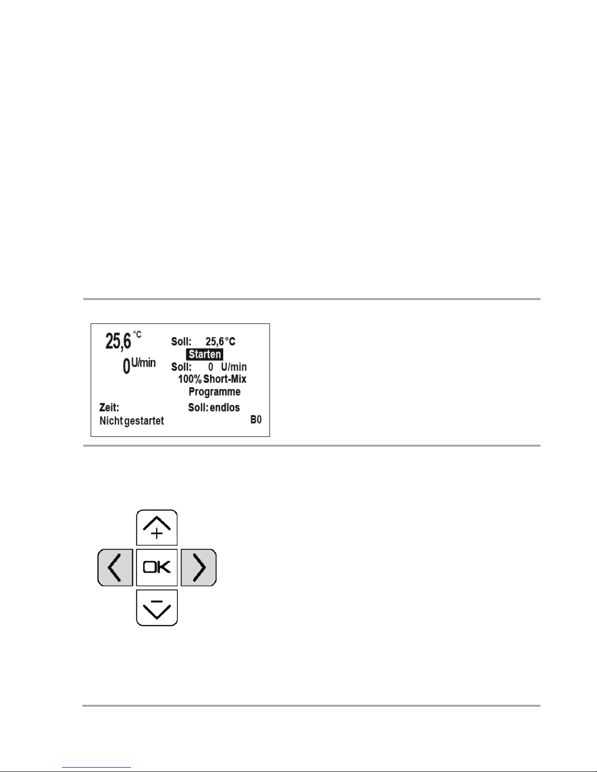
Startmenü
Dieses Menü erscheint nach dem Einschalten
des Gerätes, nach dem Abbrechen oder dem
automatischen Ende eines Prozesses.
Die letzten Sollwerte bleiben auch nach dem
Ausschalten des Gerätes erhalten.
Set-Up Menü
Drücken Sie die Pfeiltaste links und rechts
gleichzeitig, dann öffnet sich das Set-Up
Menü. Mit + und – können die Werte zum
Einstellen angewählt werden. Das angewählte Feld blinkt, mit ok wird es zum Abändern
fest hinterlegt. Mit den Tasten + und – können die Eingaben oder die Werte geändert
werden.
Wird eine Eingabe durch ok bestätigt, wird
das Feld wieder blinkend unterlegt. Über
Bestätigen des Buttons Startmenü gelangen
Sie wieder zum Startbildschirm.
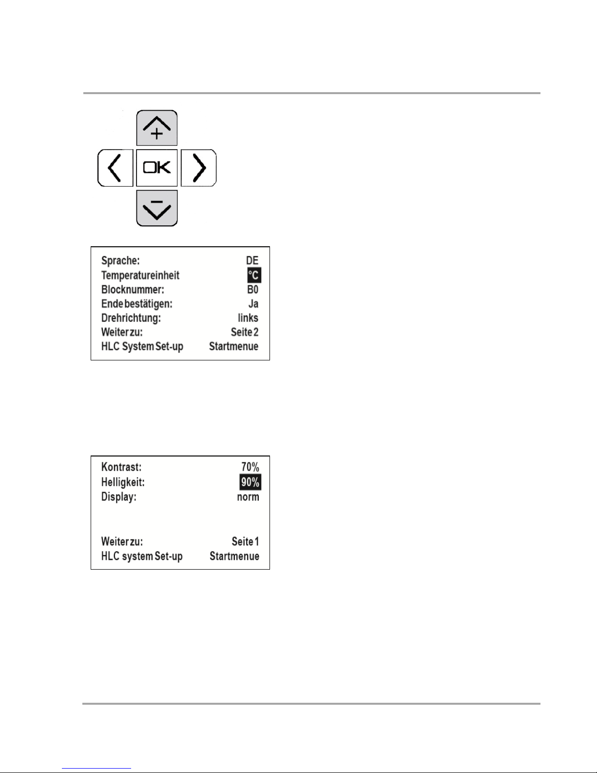
Folgende Werte können angepasst werden:
38
10-Punkt-Kalibrierung
Seite 1:
Sprache: Englisch, Deutsch, Französisch,
Spanisch
Temperatureinheit: °C oder °F
Blocknummer (10-Punkt-Kalibrierung)
Ende bestätigen:
Ja: bei Prozessende ertönt ein Signalton bis
ok gedrückt wird. So lange läuft der Prozess
mit den letzten Daten.
Nein: der Prozess endet ohne Bestätigung.
Drehrichtung: rechts, links
Seite 2:
Kontrast: angegeben in %
Helligkeit:angegeben in %
Displayfarbe: normal - inverse
Standardmäßig ist in der Software die BlockKalibrierung „B0“ eingestellt. Dieser Standard
Kalibrierung liegen 10 Stützpunkte zu Grunde.
Sie ist optimiert auf alle DITABIS Standardblö-
cke. Bei individuell angefertigten Blöcken
können Sie zusätzlich auch eine individuelle,
auf Ihre Bedürfnisse abgestimmte Kalibrierung vornehmen. Für diese individuelle Kalibrierung benötigen Sie ein geeichtes Temperaturmessgerät.
Wählen Sie im Set-Up Menü
den Punkt
„Blocknummer“ und bestätigen mit ok
. Sie
können neben dem Standardblock B1 bis zu 4
weitere individuelle Kalibrationen vornehmen
und speichern. Wechselblöcke kalibrieren

39
und abspeichern. Dazu wählen Sie B1 bis B4
aus. Bestätigen Sie erneut mit ok. Jetzt kommen Sie in das Kalibriermenü. In der ersten
und dritten Spalte sehen Sie die Temperaturstützpunkte. In der zweiten und vierten Spalte die variablen Einstellwerte. Mit den Tasten
+ und - können die Eingaben oder die Werte
geändert werden. Das angewählte Feld blinkt,
mit ok wird es zum Abändern fest hinterlegt.
Beispiel:
Sie haben das Gerät im Startmenü auf 95,0°C
eingestellt und messen direkt in der Probe
mit einem kalibrierten Thermometer nur
85,0°C. Jetzt müssen Sie den Temperaturstützpunkt um -10°C, also auf 85,0°C verändern. Auf diese Art können Sie jeden einzelnen Stützpunkt kalibrieren.
Temperatur-Sollwert
Navigieren Sie mit + und – zum Temperatur-
eingabefeld und bestätigen Sie mit ok. Die
einzelnen Ziffern können mit Pfeil links und
rechts angewählt werden, ihr Wert kann mit
+ und – geändert werden. Die Eingabe wird
mit ok bestätigt und der Cursor springt auto-
mtatisch zum Button Starten.
e
e

40
Eine Sollwertänderung kann auch auf gleiche
Weise während eines laufenden Prozesses
vorgenommen werden. Nach Bestätigung der
Eingaben durch ok wird der neue Sollwert
sofort wirksam. Bei der Hunderter-Stelle
können gewählt werden:
0 für Temperaturen bis +99,9°C
1 für Temperaturen ab +100,0°C
- für Temperaturen unter 0,0°C
Wichtiger Hinweis
Bei den Kühlgeräten darf die
minimale Temperatur nicht kleiner der unten
angegebenen Differenz zur Raumtemperatur
sein.
MKR 13 / TK 23: 16°C unter Rt.
MKR 23: 11°C unter Rt.
Mix-Sollwert
Navigieren Sie mit + und – zum Schüttelfre-
quenzeingabefeld und bestätigen Sie mit ok.
Die einzelnen Ziffern können mit Pfeil links
und rechts angewählt werden, ihr Wert kann
mit + und – geändert werden. Die Eingabe
wird mit ok bestätigt und der Cursor springt
automtatisch zum Button Starten. Die EinerZiffer kann nicht ausgewählt und geändert
werden. Eine Sollwertänderung kann auch
auf gleiche Weise während eines laufenden
Prozesses vorgenommen werden. Nach Bestätigung der Eingaben durch ok wird der
neue Sollwert sofort wirksam.
Dauer des Prozesses (Zeitvorgabe)
Navigieren Sie mit + und – zum Zeiteingabe-

41
feld und bestätigen Sie mit ok. Die einzelnen
Ziffern können mit Pfeil links und rechts angewählt werden, ihr Wert kann mit + und -
geändert werden. Die Eingabe wird mit ok
bestätigt und der Cursor springt automtatisch
zum Button Starten.
Soll der Prozess endlos laufen, stellen Sie
00:00 ein.
100% Short-Mix (Vortexen)
Navigieren Sie mit + und – zum Button 100%
Short-Mix und bestätigen Sie mit ok. Das
Gerät schüttelt mit der maximalen Mixgeschwindigkeit, unabhängig davon ob ein Prozess gestartet ist oder nicht.
Programmmodus wählen
Navigieren Sie mit + und – zum Button Pro-
gramm und bestätigen Sie mit ok. Details zur
Programmierung siehe Seite 40.
Ablauf ohne Zeitvorgabe
Stellen Sie lediglich eine Soll-Temperatur und
eine Soll-Schüttelfrequenz ein, setzen sie Zeit
jedoch auf endlos 00:00, so wird die Prozess-
zeit ständig angezeigt. Diese beginnt erst zu

42
laufen, wenn der Temperatur Sollwert
erreicht ist.
Auch während eines laufenden Prozesses
können sämtliche Sollwerte - wie oben beschrieben - geändert werden. Änderungen
bleiben auch nach Beendigung des Prozesses
erhalten und erscheinen im Startmenü als
aktuelle Sollwerte.
Zum Beenden des Prozesses drücken Sie
Stoppen.
Ablauf mit Zeitvorgabe
Wird eine Prozesszeit eingestellt, wird im
Menü die Restzeit angezeigt. Die Zeit beginnt
erst zu laufen, wenn der Temperatur-Sollwert
erreicht ist. Dies gilt auch für nachfolgende
Temperaturwechsel. Auch während eines
laufenden Prozesses können sämtliche Sollwerte - wie oben beschrieben - geändert
werden. Der Prozess endet ohne Signal oder
läuft weiter mit Signal, bis er manuell gestoppt wird. Der entsprechende Modus kann
im Set-Up Menü gewählt werden.
Bei Änderungen während des Prozesses
Sind Sollwertänderungen vorgenommen
worden können Sie wählen, ob diese Änderungen gespeichert werden sollen und im
Startmenü als neue Sollwerte erscheinen.
Stoppen des Prozess vor Ablauf der Zeit
Wird der Prozess vor Ablauf der Zeit gestoppt
oder geändert, können Sie wählen, ob der
Prozess wirklich beendet werden soll oder ob
er weiter laufen soll. Je nach Wahl erscheint
das Startmenü oder die Auswahl, ob der Pro-

43
zess ab Stopp weiterlaufen soll (Zeit läuft ab
Stopp) oder ob es einen Neustart geben soll
(Zeit beginnt ab Null).
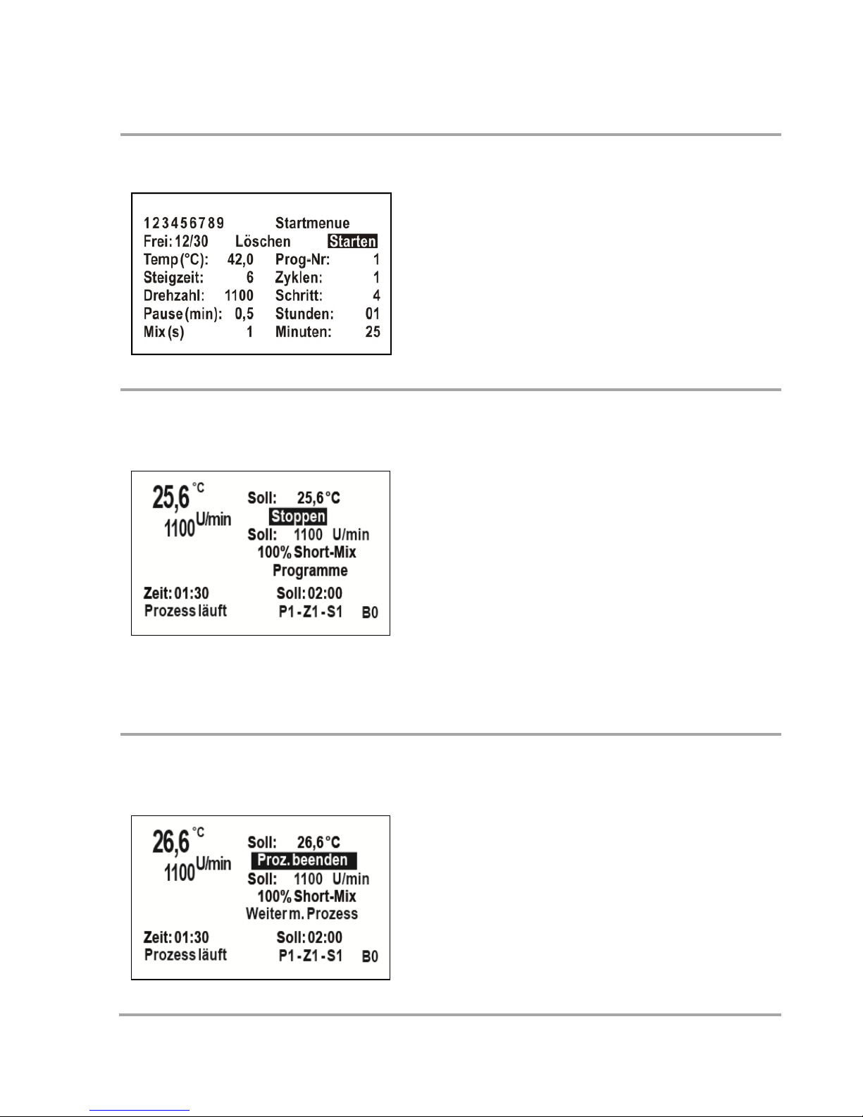
Programmierungsfunktion
Programmmenü
Navigieren Sie mit + und – zum Button
Programme und bestätigen Sie mit ok.
Es können insgesamt 30 unterschiedliche
Programmschritte vorgeben werden, die
auf max. 9 verschiedene Programme
verteilt sind.
Die "Programmnummer" ist standardmäßig mit einer 1 versehen, das Feld ist
blinkend unterlegt. Bestätigen Sie die
Programmnummer mit ok.
Mit + und – können die Programmnr. 1-9
ausgewählt werden. Soll die standarmäßige 1 oder die Änderung übernommen
werden, so drückt man ok und das Feld
"Zyklen" wird blinkend unterlegt.

44
Einstellung der einzelnen Paramater
Zyklen = Anzahl der Wiederholungen des Programmes, Auswahl von 1-9 möglich.
Soll keine Änderung vorgenommen werden, so fährt man mit - auf das nächste Feld.
Soll die Anzahl der Zyklen verändert werden, so ist ok zu drücken, das Feld wird fest
unterlegt. Der Wert kann mit den Tasten + und – zwischen 1 und 9 gewählt werden.
Ist die gewünschte Anzahl der Zyklen eingestellt, so ist dies mit ok zu bestätigen,
das Feld "Schritt" wird blinkend unterlegt.
Schritt = Teilabschnitt innerhalb eines Programmes. Auswahl von 1-9 möglich.
Soll der angezeigte Programmschritt geändert werden, so ist ok zu drücken, das
Feld wird fest unterlegt. Der Wert kann mit den Tasten + und – zwischen 1 und 30
gewählt werden. Ist der gewünschte Schritt für die folgenden Eingaben eingestellt,
so ist dies mit ok zu bestätigen, das Feld "Stunden" wird blinkend unterlegt.
Stunden = Dauer des Teilabschnitts in Stunden.
Sollen Eingaben vorgenommen werden, so ist ok zu drücken, die Einer-Stelle wird
fest unterlegt, sie kann mit den Tasten + und – gewählt werden. Soll die ZehnerStelle geändert werden, so ist mit auf die Zehner-Stelle zu fahren. Sie kann mit
+ und – gewählt werden. Ist die gewünschte Stundenzeit eingestellt, so ist diese mit
ok zu bestätigen, das Feld "Minuten" wird blinkend unterlegt.
Minuten = Dauer des Teilabschnitts in Minuten.
Sollen Eingaben vorgenommen werden, so ist ok zu drücken, die Zehner-Stelle wird
fest unterlegt, sie kann mit den Tasten + und – gewählt werden. Soll die Einer-Stelle
geändert werden, so ist mit auf die Einer-Stelle zu fahren. Sie kann mit + und –

45
gewählt werden. Ist die gewünschte Minutenzeit eingestellt, so ist diese mit
ok zu bestätigen, das Feld "Temp °C" wird blinkend unterlegt.
Zeit "endlos":
Soll ein Programmschritt (vornehmlich der letzte innerhalb eines Programmes)
endlos lange lau
fen bis das Programm manuell beendet wird, so ist sowohl bei
Stunden als auch bei Minuten jeweils eine 00 einzugeben.
Temperatur = Solltemperatur des Teilabschnitts
Der Temperatur-Sollwert ist standardmäßig mit 37,0 versehen. Sollen in dem Feld
"Temp °C" keine Eingaben vorgenommen werden, so fährt man mit –
auf das
nächste Feld. Soll der Wert geändert werden, so ist ok zu drücken, es kann jede
einzelne Ziffer geändert werden. Der Cursor steht an der Zehner-Stelle des Sollwertes. Dieser Wert kann mit den Tasten + und – geändert werden. Soll eine weitere
Stelle in diesem Datenfeld geändert werden, so muss sie mit den Tasten < und >
angefahren werden. Der fest unterlegte Wert wird wieder mit den Tasten + und –
geändert. Ist der Sollwert mit sämtlichen Ziffern eingestellt, so ist dieser mit ok zu
bestätigen, das Feld "Steigzeit" wird blinkend unterlegt.
Steigzeit = Zeitangabe, in der die Probe auf die Solltemperatur temperiert werden
soll. Diese Angabe ist nur nötig, wenn die Probe langsamer als die Voreinstellung
temperiert werden soll. Soll die Probe schnellstmöglich temperiert werden, hinterlegen Sie den Wert 0.
Man kann vorgeben, in wieviel Minuten die in dem aktuellen Schritt eingegebene
Temperatur erreicht werden, wenn langsamer temperiert werden soll als dies tech-
nisch möglich ist. Im unten aufgeführten Beispiel soll die Temperatur von 60,0°C

46
des Schrittes 2 innerhalb von 20 Minuten von der Temperatur 37,0°C des Schrittes 1
erreicht werden. (Die max. Eingabe bei der Steigzeit beträgt 99 min). Sollen in dem
Feld "Steigzeit" keine Eingaben vorgenommen werden (schnellstmögliche Heiz-
bzw. Kühlzeit), so fährt man mit – auf das nächste Feld. Soll der standardmäßige
Wert 0 verändert werden, so ist ok zu drücken, die Einer-Stelle wird fest unterlegt,
sie kann mit den Tasten + und – gewählt werden. Soll die Zehner-Stelle geändert
werden, so ist mit auf die Zehner-Stelle zu fahren. Sie kann mit + und - gewählt
werden. Ist die gewünschte Steigzeit eingestellt, so ist diese mit ok zu bestätigen,
das Feld "Drehzahl" wird blinkend unterlegt.
Beispiel eines Temperaturprogrammes
Drehzahl = Schüttelfrequenz, mit der die Blöcke geschüttelt werden sollen.
Die Einer-Ziffer kann nicht ausgewählt und geändert werden.
Soll der Wert geändert werden, so ist ok zu drücken, es kann jede einzelne Ziffer
geändert werden. Der Cursor steht an der Hunderter-Stelle des Sollwertes. Dieser
Wert kann mit den Tasten + und – geändert werden. Soll eine weitere Stelle in
diesem Datenfeld geändert werden, so muss sie mit den Tasten < und > angefahren
werden. Der fest unterlegte Wert wird wieder mit den Tasten + und – geändert. Die
letzte Einer-
Ziffer kann nicht ausgewählt und geändert werden. Ist der Sollwert
eingestellt, so ist dieser mit ok zu bestätigen, das Befehlsfeld "Pause"wird blinkend
unterlegt.

47
Intervall-Schütteln = Will man die Probe nicht ständigem Schütteln aussetzen, so
kann man dies mit dem "Intervall-Mixen" ermöglichen.
Es kann eine Ruhezeit in "Pause" von bis zu 9,9 Minuten vorgegeben werden. Die
darauf folgende kurze Schüttelzeit wird in "Mix sec" bis zu 9 Sekunden eingegeben.
Besonders sinnvoll scheint diese Wahl beim letzten Programmschritt eines Pro-
grammes mit der zeitlichen Eingabe von "endlos", wenn das Labor z.B. unbesetzt
ist, um das Programm komplett abzuschließen. Stellen Sie die Intervalle mit Pause
[min] und Mix [s] ein.
Pause [min] = Ruhezeit von bis zu 9,9 Minuten. Sollen keine Intervalle ausgeführt
werden, geben Sie hier den Wert 0,0 an. Die Pausenzeit ist standardmäßig mit 0,0
versehen.
Sollen in dem Feld "Pause" keine Eingaben vorgenommen werden, so fährt man mit
– auf das nächste Feld "Schritt". Soll der Wert geändert werden, so ist ok zu drü-
cken, es kann jede einzelne Ziffer geändert werden. Nach dem Druck von ok wird
die Einer-Stelle unterlegt, sie kann mit den Tasten + und – gewählt werden. Soll die
Zehntel -Stelle geändert werden, so dückt man auf die Taste >, die Ziffer wird unterlegt, sie kann mit + und – gewählt werden. Ist eine Pausenzeit eingestellt, so ist
diese mit ok zu bestätigen, das Feld "Mix sec" wird blinkend unterlegt.
Mix [s] = Kurze Schüttelzeit bis zu 9 Sekunden nach Ruhepause.
In dem Feld "Mix sec" steht standardmäßig eine 1 wenn es angefahren wird. Sollen
in dem Feld "Mix sec" keine Eingaben vorgenommen werden, so fährt man mit –
auf das nächste Feld "Schritt". Soll die Schüttelzeit geändert werden, so ist ok zu
drücken, sie kann mit den Tasten + und – gewählt werden. Ist die gewünschte Zeit
eingestellt, so ist diese mit ok zu bestätigen, das Feld "Schritt" wird blinkend unter-
legt.
Eingaben weiterer Programmschritte
Soll innerhalb des gewählten Programmes
ein weiterer Programmschritt eingegeben
werden, so ist bei dem blinkend unterleg-
ten Feld "Schritt" die Taste ok zu drücken,

48
die Zahl des letzten Programmschrittes
muss um eins erhöht werden. Die weitere
Eingabe erfolgt wie bereits beschrieben.
Ändern der Programmeingaben
Soll das gewählte Programm geändert
werden, so ist die Nummer des Programmschrittes einzugeben, in dem Änderungen vorgenommen werden sollen.
Das zu ändernde Feld kann mit den Tas-
ten + und – ausgewählt werden (wird
blinkend unterlegt). Zur Änderung ist ok
zu drücken, die Änderung erfolgt jeweils
wie bei der Eingabe beschrieben, sie muss
mit ok bestätigt werden. Mit den Tasten
+ und – wird ein entsprechendes
Feld angefahren.
Beenden der Programmeingaben
Soll das gewählte Programm beendet
werden, so gelangt man mit der Taste +
zu den Feldern "Starten" (um das
Programm sofort zu starten).
49
Starten eines Programmes
Wählen Sie die entsprechende
Programmnummer und bestätigen Sie
den Starten-Button im Programmenü.
Änderungen der Parameter während
des Programmablaufs
Änderungen der Temperatur und Drehzahl sowie das Durchführen des ShortMixes sind während eines laufenden
Programms möglich.
Als Sollzeit wird die Gesamtzeit des Programmschrittes, als Restzeit die des laufenden Prozesses angegeben. Im Display
unten rechts werden Programmnummer,
Zyklus und Schritt angezeigt.
Beenden / Unterbrechen des
Programms:
Wenn Sie Stoppen bestätigen, erscheinen
die Optionen Proz. Beenden und Weiter
mit Proz.
Bei der Wahl von Proz. Beenden erscheint
Startmenue oder Änderungen speichern,

50
falls während des Prozesses Änderungen
an den Parametern vorgenommen wurden.
Wählt man Weiter mit Proz. erscheint die
Auswahl Weiter ab Stopp oder Proz.
Neustart (Programm startet bei Zyklus 1,
Schritt 1).
Montage von Zubehörteilen
Antikondensplatte BA 24 / 96
Die Antikondensplatte BA 96 (800013000) wird auf den festgeschraubten
Block gesetzt, es sind keine Montageschritte erforderlich. Zur Verwendung
der Antikondensplatte BA 24 (800012900) entfernen Sie die Innensechskantschraube in dem Block mit dem beiliegenden Schraubendreher. Schrauben Sie
den beiliegenden Gewindestift mit Isolierknopf in die Antikondensplatte.
Legen Sie die Antikondensplatte auf den Block und schrauben Sie den Gewindestift weiter, sodass sie in den Bolzen des Gerätes fasst somit den Block und
die Antikondensplatte fest mit dem Gerät verbindet.

51
Datentransfer
Eine USB 1.1. Schnittstelle zur Kommunikation mit einem PC ist serienmäßig
vorhanden. Verbinden Sie das Gerät über den USB-Anschluss an der linken
Seite mit einem USB-Kabel mit Ihrem PC. Falls auf Ihrem Rechner noch nicht
vorhanden, installieren Sie den geeigneten USB-Treiber. Diesen finden Sie
unter www.ftdichip.com/Drivers/VCP.htm. Diese USB-Treiber erzeugen im PC
eine neue virtuelle COM-Schnittstelle. Der Chip in der Smart Control heißt
FT232B.
Prozessdaten über USB entnehmen
Starten Sie auf Ihrem Rechner ein Terminal-Programm (z.B. Hyper-Terminal).
Dieses Programm finden Sie unter Windows in "Programme" / "Zubehör"/
"Kommunikation". Es wird das Fenster "Hyper Terminal" geöffnet. Gehen Sie
systematisch weiter vor, beachten Sie, dass bei der Anschlusseinstellung bei
"Bits pro Sekunde" 115200 gewählt wird. Wählen Sie bei "Übertragung": "Text
aufzeichnen", geben den Speicherort an und bestimmen den Dateinamen als
.txt Starten Sie Hyper Terminal und den Prozess. Jede Minute werden folgende Daten im Textformat aufgezeichnet und durch ein Komma getrennt:
Zeit ab Start (hh:mm) Zeit ab neuem Programmschritt
Temperatur in °C (tmp) (step time)
Drehzahl in 1 / min. (rpm) Steigzeit (rem. risetime_m)
Programm-Nr. (prg.) Intervall Mix (mix_s)
Zyklus (cycle) Intervall Pause (pause_m)
Programmschritt (step)
Wenn Sie die Textdatei öffnen, die Sie zum Speichern gewählt haben, können
Sie sich den gesamten Prozessablauf in nebenstehender Form ansehen. Da die
Daten durch Kommas getrennt sind, können Sie sich auf einfache Art eine
Excel-Datei erstellen und daraus eine oder mehrere Kurven erzeugen.

52
START
Sollwerte / Setpoints
xx:xx,+37.0,0200,01,01,01,00:01,00,9,0.2
time hh:mm,tmp,rpm,prg,cycle,step,steptime hh:mm,rem.
risetime_m,mix_s,pause_m
00:00,+26.9,0000,01,01,01,00:00,00,9,0.2
00:01,+33.7,0220,01,01,01,00:00,00,9,0.2
00:02,+36.7,0000,01,01,01,00:00,00,9,0.2
00:03,+36.9,0000,01,01,01,00:00,00,9,0.2
START
Sollwerte / Setpoints
xx:xx,+70.0,0300,01,01,02,00:12,10,9,0.1
time hh:mm,tmp,rpm,prg,cycle,step,steptime hh:mm,rem.
risetime_m,mix_s,pause_m
00:04,+36.9,0000,01,01,02,00:00,10,9,0.1
00:05,+39.1,0000,01,01,02,00:01,09,9,0.1
00:06,+42.1,0000,01,01,02,00:02,08,9,0.1
00:07,+45.2,0300,01,01,02,00:03,07,9,0.100:08,+48.4,0300,01,01,02,00:04,06
,9,0.1
00:09,+51.7,0000,01,01,02,00:05,05,9,0.1
00:10,+54.9,0000,01,01,02,00:06,04,9,0.1
00:11,+58.2,0300,01,01,02,00:07,03,9,0.1
00:12,+61.5,0300,01,01,02,00:08,02,9,0.1
00:13,+64.7,0000,01,01,02,00:09,01,9,0.1
STOP
Prozessdaten über USB eingeben
Zur Prozesssteuerung eines HLC by DITABIS Gerätes mit Smart Control über
eine USB-Schnittstelle sind 4 Befehle möglich und notwendig:
Start
Startet einen Prozess ohne Programm mit den Parametern, die auf dem Display stehen. Eine eventuelle Zeitvorgabe wird gelöscht und durch endlos
überschrieben da zeitlich Abläufe am Rechner programmiert werden müssen.

53
Stopp
Stoppt jeden Prozess und führt zum Startmenü zurück, laufende Programme
/ Prozesse werden abgebrochen.
t=0370
Verändert die Solltemperatur auf einen neuen Wert.
Die Temperatur muss immer vierstellig eingegeben werden.
t=0370 stellt 37,0°C ein, t=0050 stellt 5,0°C ein, t=-060 stellt -6,0°C ein.
t= ist das Erkennungszeichen für einen Temperaturwert. Der Zahlenwert dahinter gibt den Wert in Zehntelgrad an. An der ersten Stelle nach dem = kann
eine 0, eine 1 oder ein Trennstrich stehen. Ungültige Temperaturwerte werden -wie bei der Eingabe am Gerät- durch den nächsten gültigen Wert ersetzt.
r=020
Verändert die Solldrehzahl auf einen neuen Wert.
Die Drehzahl muss immer dreistellig eingegeben werden.
r=120 stellt 1.200 1/min ein, r=045 stellt 450 1/min ein.
r= ist das Erkennungszeichen für einen Drehzahlwert. Der Zahlenwert dahinter
gibt den Wert in 10 1/min an. Ungültige Drehzahlwerte werden -wie bei der
Eingabe am Gerät- durch den nächsten gültigen Wert ersetzt.
r=000
Stoppt die Drehzahl, wenn z.B. nicht mehr geschüttelt aber weiter temperiert
werden soll.
Andere Eingaben, wie z.B. r=0 werden als Drehzahl interpretiert und lassen
den Motor mit der Mindestdrehzahl drehen.
Jeder Befehl muss mit einem "CR" abgeschlossen werden
Bei unbekannten Befehlen und / oder bei Fehlern in der Schreibweise wird
nichts ausgeführt. Die Eingaben im Set-Up-Menü, wie Farbe, Kontrast und
Helligkeit des Displays, die Sprache, die Drehrichtung usw. können nur durch
das Bedienteil am Gerät selbst vorgenommen werden.

54
Problembehebung
Das Display bleibt dunkel
Bitte überprüfen Sie, ob der Hauptschalter an der Rückseite eingeschaltet ist.
Falls dies nicht der Fall ist, an der Steckdose aber Spannung anliegt, prüfen Sie
die Feinsicherung und tauschen diese ggf. aus. (IEC 127-2/III, 250 V, 2 A träge).
Diese Sicherung - und eine Ersatzsicherung - befinden sich in der IEC-Buchse
(in die das Anschlusskabel gesteckt ist). Mit einem Schraubendreher lässt sich
der Sicherungskasten herausziehen.
Das Gerät kühlt, heizt oder schüttelt nicht wie eingestellt
Überprüfen Sie, ob das Display beim Einschalten des Gerätes die richtige Gerätetypenbezeichnung anzeigt. Falls dies nicht der Fall sein sollte, kontaktieren Sie bitte Ihren Händler vor Ort oder die HLC by DITABIS Servicabteilung.
Es entstehen große Temperaturschwankungen
Prüfen Sie den Sitz des Wechselbockes durch Hochziehen. Wenn dieser zu
locker angeschraubt ist oder der Block Unebenheiten z. B. Verschmutzungen
aufweist, wird die Wärme / Kälte nicht korrekt übertragen.
Hinweise zum kapazitiven Touchdisplay
Das Touchdisplay reagiert auf Fingerdruck, auch in dünnen LatexHandschuhen, jedoch nicht auf Stylos. Aufgrund der Glasoberfläche ist die
Frontscheibe sehr unempfindlich gegen Schmutz, Chemikalien und mechanische Beschädigungen. Vermeiden Sie Kratzer in der Beschichtung, da diese zu
Störungen führen könnten. Bitte beachten Sie die nachfolgenden Reinigungshinweise.

55
Instandhaltung
Reinigung
Reinigen Sie regelmäßig das Gehäuse der und die Wechselblöcke der
Thermomixer und Blockthermostate.
Vorsichtsmaßnahmen zur Vermeidung von Stromschlägen
Elektrische Geräte können bei Fehlbedienung einen Stromschlag
verursachen. Versuchen Sie niemals elektrische Teile zu reparieren. Öffnen Sie niemals das Gerätegehäuse.
• Schalten Sie das Gerät aus und trennen Sie es von der
Stromversorgung, bevor Sie mit der Reinigung bzw. Des-
infektion beginnen.
• Lassen Sie keine Flüssigkeiten in das Gehäuseinnere ge-
langen (Lüftungsschlitze).
• Führen Sie keine Sprühdesinfektion durch.
• Schließen Sie das Gerät erst vollständig trocken wieder
an die Stromversorgung an.
Der Reparaturservice darf nur durch autorisiertes und geschultes
Personal vorgenommen werden. Eine Modifikation des Gerätes
ist nicht zulässig.
Vorsicht bei Verwendung von aggressiven Chemikalien
Verwenden Sie an dem Gerät und Zubehör keine aggressiven
Chemikalien wie z.B. starke und schwache Basen, starke Säuren,
Formaldehyd, Aceton, halogen
ierte Kohlenwasserstoffe oder
Phenol.
• Reinigen Sie das Gerät bei Verunreinigungen durch ag-
gressive Chemikalien umgehend mit einem neutralen
Reinigungsmittel.
• Verwenden Sie weder ätzende Reinigungsmittel, noch
aggressive Lösungs- oder schleifende Poliermittel.

56
Reinigung
1. Trennen Sie das Gerät bitte von der Stromversorgung, bevor Sie mit
der Reinigung beginnen.
2. Reinigen Sie alle äußeren Teile des Geräts bitte mit einer milden Sei-
fenlösung und einem fusselfreien Tuch.
3. Entfernen Sie die Seifenlösung mit Aqua dest.
4. Bitte trocknen Sie alle gereinigten Teile sorgfältig ab.
Desinfektion
1. Trennen Sie das Gerät bitte von der Stromversorgung, bevor Sie mit
der Desinfektion beginnen.
2. Lassen Sie das Gerät abkühlen.
3. Reinigen Sie das Gerät bitte wie oben aufgeführt.
4. Wählen Sie eine Desinfektionsmethode, die den für Ihren Anwen-
dungsbereich geltenden gesetzlichen Bestimmungen und Richtlinien
entspricht.
5. Wischen Sie bitte alle äußeren Teile des Geräts mit dem Desinfekti-
onsmittel und einem fusselfreien Tuch ab.
Service
Falls ein technisches Problem auftritt, kontaktieren Sie bitte Ihren Händler vor
Ort oder die DITABIS Serviceabteilung. Hier wird eine erste Einschätzung des
Defekts durchgeführt. Die DITABIS Kontaktdaten finden Sie unter
www.ditabis.com. Falls notwendig, wird das Gerät zur Reparatur eingeschickt
– beachten Sie hierzu bitte die Servicerichtlinien, welche auf www.ditabis.com
zu finden sind.
Dekontamination vor Versand
Wenn Sie das Gerät im Reparaturfall zum autorisierten technischen Service
oder im Entsorgungsfall zu Ihrem Vertragshändler schicken, dekontaminieren
Sie bitte alle Teile, die Sie versenden möchten. Dokumentieren Sie die Dekontamination in einer Dekontaminationsbescheinigung (inkl. Seriennummer)
und legen Sie bitte diese beim Versand bei.

57
Technische Daten
Technische Daten
MKR 13
Temperatur-Arbeitsbereich
Rt. -16°C bis +100°C
Temperatur-Einstellbereich
-10°C bis +105°C
Genauigkeit / Auflösung
+/- 0,1°C / 0,1°C
Max. Heizgeschwindigkeit
6,0°C / min
Max. Kühlgeschwindigkeit
12,0°C / min
Schüttelfrequenz
200 – 1.500 U / min
Schüttelhub
3 mm rund
Abmessungen (ohne Block) B x T x H
220 x 330 x 144 mm
Block - Kapazität
1 Wechselblock
Gewicht (ohne Block)
9,0 kg
Leistungsaufnahme
130 W
Netzanschluss
230 V / 50 Hz
(115 V / 60 Hz verfügbar)
Sicherung
2 AT
Schutzklasse
IP21
Umgebungsbedingungen
Umgebungstemperatur
3° – 50°C
bei Betrieb (nicht betauend)
Relative Luftfeuchtigkeit
max. 80%
Technische Daten
MKR 23
Temperatur-Arbeitsbereich
Rt. -11°C bis +70°C
Temperatur-Einstellbereich
0°C bis +80°C
Genauigkeit / Auflösung
+/- 0,3°C / 0,1°C
Max. Heizgeschwindigkeit
3,5°C / min
Max. Kühlgeschwindigkeit
6,5°C / min
Schüttelfrequenz
200 – 1.200 U / min
Schüttelhub
3 mm rund

58
Abmessungen (ohne Block) B x T x H
220 x 330 x 144 mm
Block - Kapazität
2 Wechselblöcke
Gewicht (ohne Block)
9,5 kg
Leistungsaufnahme
200 W
Netzanschluss
230 V / 50 Hz
(115 V / 60 Hz verfügbar)
Sicherung
2 AT
Schutzklasse
IP21
Umgebungsbedingungen
Umgebungstemperatur
3° – 50°C
bei Betrieb (nicht betauend)
Relative Luftfeuchtigkeit
max. 80%
Technische Daten
MHR 13
Temperatur-Arbeitsbereich
Rt. +3°C bis +130°C
Temperatur-Einstellbereich
0°C bis +137°C
Genauigkeit / Auflösung
+/- 0,1°C / 0,1°C
Max. Heizgeschwindigkeit
11,5°C / min.
Schüttelfrequenz
200 – 1.500 U / min
Schüttelhub
3 mm rund
Abmessungen (ohne Block) B x T x H
220 x 330 x 109 mm
Block - Kapazität
1 Wechselblock
Gewicht (ohne Block)
6,5 kg
Leistungsaufnahme
200 W
Netzanschluss
230 V / 50 Hz
(115 V / 60 Hz verfügbar)
Sicherung
2 AT
Schutzklasse
IP21
Umgebungsbedingungen
Umgebungstemperatur
3° – 50°C
bei Betrieb (nicht betauend)
Relative Luftfeuchtigkeit
max. 80%

59
Technische Daten
MHR 23
Temperatur-Arbeitsbereich
Rt. +3°C bis +130°C
Temperatur-Einstellbereich
0°C bis +137°C
Genauigkeit / Auflösung
+/- 0,1°C / 0,1°C
Max. Heizgeschwindigkeit
9,5°C / min
Schüttelfrequenz
200 – 1.500 U / min
Schüttelhub
3 mm rund
Abmessungen (ohne Block) B x T x H
220 x 330 x 109 mm
Block - Kapazität
2 Wechselblöcke
Gewicht (ohne Block)
7,0 kg
Leistungsaufnahme
350 W
Netzanschluss
230 V / 50 Hz
(115 V / 60 Hz verfügbar)
Sicherung
2 AT
Schutzklasse
IP21
Umgebungsbedingungen
Umgebungstemperatur
3° – 50°C
bei Betrieb (nicht betauend)
Relative Luftfeuchtigkeit
max. 80%
Technische Daten
MHL 23
Temperatur-Arbeitsbereich
Rt. +3°C bis +130°C
Temperatur-Einstellbereich
0°C bis +137°C
Genauigkeit / Auflösung
+/- 0,1°C / 0,1°C
Max. Heizgeschwindigkeit
9,5°C / min
Schüttelfrequenz
200 – 1.300 U / min
Schüttelhub
3 mm linear
Abmessungen (ohne Block) B x T x H
220 x 330 x 109 mm
Block - Kapazität
2 Wechselblöcke
Gewicht (ohne Block)
7,0 kg
Leistungsaufnahme
350 W

60
Netzanschluss
230 V / 50 Hz
(115 V / 60 Hz verfügbar)
Sicherung
2 AT
Schutzklasse
IP21
Umgebungsbedingungen
Umgebungstemperatur
3° – 50°C
bei Betrieb (nicht betauend)
Relative Luftfeuchtigkeit
max. 80%
Technische Daten
TK 23
Temperatur-Arbeitsbereich
Rt. -16°C bis +90°C
Temperatur-Einstellbereich
-10°C bis +105°C
Genauigkeit / Auflösung
+/- 0,3°C / 0,1°C
Max. Heizgeschwindigkeit
4,0°C / min
Max. Kühlgeschwindigkeit
7,0°C / min
Abmessungen (ohne Block) B x T x H
220 x 330 x 144 mm
Block - Kapazität
2 Wechselblöcke
Gewicht (ohne Block)
7,5 kg
Leistungsaufnahme
130 W
Netzanschluss
230 V / 50 Hz
(115 V / 60 Hz verfügbar)
Sicherung
2 AT
Schutzklasse
IP21
Umgebungsbedingungen
Umgebungstemperatur
3° – 50°C
bei Betrieb (nicht betauend)
Relative Luftfeuchtigkeit
max. 80%

61
Artikelbezeichnung Blöcke & Zubehör
Blöcke
Art.-Nr.
Maße der Gefäße
Für
800010800
BM 02 für 96 x 0,2 ml konisch & 8er Gefäßstreifen
Mikro-
800010900
BM 05 für 38 x 0,5 ml konisch
gefäße
800011000
BM 15 für 24 x 1,5 ml konisch
800011100
BM 20 für 24 x 2,0 ml zylindrisch
Für Proben-
800011500
BP 10 für 24 x D=10,3 mm, 46 mm tief, Rundboden, Deckel
gläser
800011600
BP 12 für 24 x D=12 mm, 20 mm tief, Flachboden
800011700
BP 15 für 24 x D=15 mm, 30 mm tief, Flachboden
800011800
BP 16 für 24 x D=16,5 mm, 46 mm tief, Rundboden, Deckel
800014200
BP 17.0 für 24 x D=17 mm, 30 mm tief, Flachboden
800016100
BP 19.2 für 24 x D=18,7 mm, 25 mm tief, Flachboden
800015200
BP 23.0 für 12 x D=22,5 mm, 56 mm tief, Flachboden
800016000
BP 25.5 für 12 x D=23,0 mm, 56 mm tief, Flachboden
800011900
BP 28 für 8 x D=28 mm, 40 mm tief, Flachboden
Für Zentri-
800012200
BZ 15 "Falcon"-Röhrchen 14 x 15 ml, mit Isolierdeckel
fugengläser
800012300
BZ 50 für "Falcon"-Röhrchen 6 x 50 ml, mit Isolierdeckel
für PCR-
800010400
BC 96 für 96-Well "V"-Boden
Platten
800010300
BC 84 für 384-Well
Für Mikro-
800012000
BV 96 für 96 x Rund- oder "V"-Boden
platten
800010600
BF 96 für Flachboden
Für DeepWell-Platten
800010500
BD 96 für 96er Deep-Well-Platten
Für andere
800011200
BN 10 für 36 Rechteckküvetten 12,5 mm außen
Anwendungen
800012100
BW 01 als Wanne für Deep-Well, gestapelte Mikrotiter-platten und
andere Gefäße, inkl. Isolierdeckel und Entnahmevorrichtung
800014100
SO 10.4 für 24 x D=10,4 mm, 180 mm tief
800012600
SO 12.0 für 24 x 12ml Gefäße
800012700
SO 20.5 für 12 x 20ml Gefäße
Für Eigen-
800010700
BM 00 ohne Bohrung, 25 mm hoch
anferti-
800011300
BO 37 ohne Bohrungen, 37 mm hoch
gungen
800011400
BO 50 ohne Bohrungen, 50 mm hoch
Für Slides
800012400
BY 12 für 12 Slides für Hybridisierung

62
Zubehör
Art.-Nr.
Beschreibung
800012800
BI 01 Isolierdeckel
800013800
BT 01 Temperierhaube für 1 Block, transparent
800013900
BT 02 Temperierhaube für 2 Blöcke, transparent
800012900
BA 24 Antikondensplatte für 1 Block (Mikrogefäße)
800013000
BA 96 Antikondensplatte für 1 Block (PCR / Testplatten)
800012500
BH 10 Heizdeckel zum Anschluss an Kühlgeräte
800013100
BR 05 Bestückungs-Rack mit Ständer f. Gefäße 0,5 ml
800014300
BR 15 Bestückungs-Rack mit Ständer f. Gefäße 1,5 / 2,0ml

63
Erläuterungen
Achtung! Risiko von elektrischem Schock!
Achtung!
Achtung! Heiße Oberfläche!
Wichtige Information
Schutzleiteranschluss
Sicherung
i

64
800-68-13-03_Manual_Smart_Control_EU.doc
 Loading...