

HKS lazar Smart Fire SF 21 Operation Manual
Operation manual
pellets burning automatic boiler
Smart Fire
This manual shall be kept by the user.
Obey thoroughly instruction found here to facilitate long and safe operation of the boiler and preserve the warranty.
All rights reserved.
Last update 07/05/2010
Instrukcja Smart Fire wer. 07/05/2010/ENG
HKS LAZAR str.1

Dear User
Thanks for your trust in our product. We hope and will take all steps necessary to make you
satisfied with it.
The Smart Fire boiler you purchased belongs to the most advanced of pellets burning systems in the
market. Pellets are recognised environmentally friendly solid fuel. The boiler has been designed and
manufactured following the latest trends and the most advanced technology available. These
solutions provide for a very high heat efficiency above 91% within the entire range of the assumed
output.
The Smart Fire boiler has been supplied with the following parts and fixtures that reduce your
hustle while operating:
• advanced ceramic burner with automating clearing system;
• heat exchange access for manual cleaning ;
• automatic lighter.
Please read the Manual and the attached manual of the control panel, as this is necessary for safe
operation of the boiler. Do not hesitate to contact us should you had any enquires.
Best Regards
Marcin Lazar
Instrukcja Smart Fire wer. 07/05/2010/ENG
HKS LAZAR str.2

1. General information .......................................................................................................................... 4
2. Recommendations ............................................................................................................................ 4
3. Safety rules ....................................................................................................................................... 4
4. Boiler's data ...................................................................................................................................... 6
5. Boiler construction ........................................................................................................................... 7
6. Type of fuel ..................................................................................................................................... 13
7. User's operations manual ................................................................................................................ 14
7.1. Launch of the boiler operation ................................................................................................ 14
7.2. Boiler's operation ..................................................................................................................... 14
7.3. Maintenance and cleaning ....................................................................................................... 16
7.4. Extinguishing of the boiler. ..................................................................................................... 17
8. Service operations manual .............................................................................................................. 18
8.1. Transport of the boiler into the building. ................................................................................. 19
8.2. Boiler room - placement of the boiler ..................................................................................... 19
8.3. Boiler's installation .................................................................................................................. 20
9. Service operations manual .............................................................................................................. 23
9.1. Launch control ......................................................................................................................... 23
9.2. Launch ..................................................................................................................................... 23
9.3. Repairs of the break downs. .................................................................................................... 23
9.4. Annual inspection. ................................................................................................................... 24
10. Scraping of the system after its lifetime. ...................................................................................... 24
11. Terms of warranty and liability .................................................................................................... 25
12. Declarations and licensing ............................................................................................................ 27
Instrukcja Smart Fire wer. 07/05/2010/ENG
HKS LAZAR str.3

1. General information
Smart Fire boiler is and advanced heating system burning pellets.
The system includes: thermo-control system, a system facilitating manual cleaning of the heat
exchange, advanced ceramic burner, automatic system of burner clearing, and an automatic lighter.
The boiler can provide heat to the central heating system in a building, with pump or gravitational
circulation, as well as hot tap water.
Smart Fire has been rated as low-temperature system and therefore needs no registration with the
local authorities in most jurisdictions.
Solid fuel boilers operating in a closed circuit are sometimes subject to a limited technical
supervision. Once the boiler is installed, the user may need to notify the local supervising
authorities before launching operation.
2. Recommendations
Initial launch and the all relating tasks and any service work can only be completed by the
manufacturer's or authorised service team.
Only fuel specified herein can be burned.
The boiler must be regularly maintained as specified in this Operation Manual.
Always observe the requirements set in this manual
Failure in submission to the provisions of the manual will result in loss of warranty and exempt the
manufacturer of responsibility of the outcome of the system's operation.
You shall observe the general rules applicable to heating technology to protect the system of
legionellosis.
3. Safety rules
Read these rules before launching operation. Failure in submission to the instruction may lead
to: casualty, loss of health, life hazard, damage to the system, the heating installation and the
Instrukcja Smart Fire wer. 07/05/2010/ENG
HKS LAZAR str.4

building!
Only persons holding necessary licences, knowledge, skills and equipment can be trusted with
assembly of the boiler.
The installation must satisfy all standards and rules in force and the principles of construction craft.
The boiler can only be operated when both the boiler and the heating installation are in perfect state
of repair. Breaks, defects and disturbances in operation must be immediately reported to the relevant
authorities.
Before launch and then regularly every six months, check if the heating system contains enough
water.
Never open the inspection openings when the boiler is working as this may release dust and exhaust
that next can ignite and explode,
Never attempt any repairs or reassembly,
Never remove the covers as movable pieces and electric devices are installed behind.
Extinguish the boiler and wait till it cools down before start of any maintenance work with the
boiler.
At least once a month check the doors and the water inlets and outlets for tightness.
At least once a year check operation of the STB fuse.
Facilitate the boiler room with a sign prohibiting smoking and use of fire.
Ventilating system must be operable and satisfy all relevant requirements.
Operable extinguisher must be available in the boiler room.
The boiler room must be secured against entry of unauthorised persons, in particular children.
Never remove or disable any safety or measurement devices.
Use gloves, dust mask and overalls when clearing ash and cleaning the boiler.
The boiler must only be installed in the premises designated thereof and satisfying the applicable
requirements.
Extinguish the boiler when fuel is delivered.
If the temperature of tap water has been set up above 60ºC, warrant admixture of cold water as this
creates risk of burning injury.
Facilitate proper air removal off the boiler and the heating system.
Use only manufacturer's spare parts.
Instrukcja Smart Fire wer. 07/05/2010/ENG
HKS LAZAR str.5

4. Boiler's data
Model
Parameter Unit SF 21
Class Class 3 (topmost)
Efficiency % 91,4 ÷ 92,9%
Nominal output kW 21
Range of output kW 6 ÷ 21
Fuel consumption at nominal output kg/h c. 5
Time till burn-out at nominal output h c. 20
Width
*-with optional larger fuel container
mm 850 / 1100*
Height mm 1410
Depth mm 635
Water volume dm
3
64
Exhaust outlet diameter ext./int. mm 120 /110
Water feeding and return connectors inch 1¼
Top operation water pressure bar 1,2
Top test water pressure bar 2,0
Safety vent bar 1,2
Water flow resistance in the boiler ΔT=10K mbar 1,9
Water flow resistance in the boiler ΔT=20K mbar 7,5
Required chimney draught Pa 10
Exhaust temperature at maximum output
0
C 100
Exhaust temperature at minimum output
0
C 50
Maximum temperature of the boiler
0
C 85
Recommended temperature of the boiler
0
C 65 ÷ 80
Minimum temperature of the returning water
0
C 50
Exhaust flow at the nominal output g/s 15
Exhaust flow at the minimal output g/s 5
CO emission at the nominal output (10% O2) mg/m
3
160
CO emission at the minimal output (10% O2) mg/m
3
800
CO emission at the nominal output (13% O2) mg/m
3
116
CO emission at the minimal output (13% O2) mg/m
3
582
Noise dB below 65
Electricity plug-in 1 PEN ~50Hz 230V TN-S
Instrukcja Smart Fire wer. 07/05/2010/ENG
HKS LAZAR str.6

Electric insulation IP 20
Electric power consumption (fans and
motoreducer)
W 90
Fuel container capacity
*-optional larger fuel container
dm
3
150 / 250*
Ash tray volume dm
3
3,5
Outlet fan Model R2A1500-AA
Motoreducer model ISG-3240RTF 3.8
Table 1. Smart Fire boiler specifications
5. Boiler construction
Smart Fire boiler has been designed as compact structure. Most of the boiler pieces are hidden
behind the covers which protects them against elements and mechanical damage.
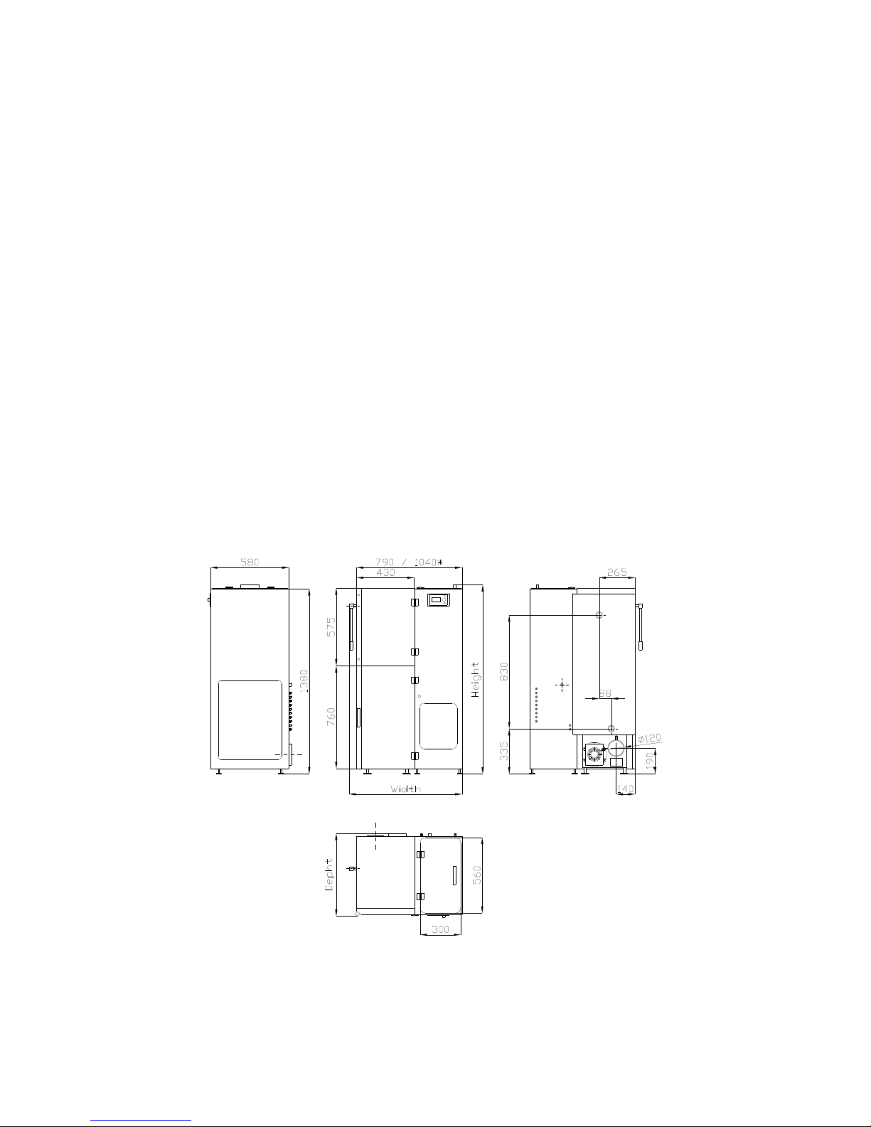
Smart Fire boiler, its dimensions and placement of the connectors to the heating system and the
chimney outlet have been shown at the fig. 1. Figures 2-4 show the boiler specifying its main
systems.
There two main elements within the Smart Fire box: the boiler's body and the fuel supply system.
The body includes: a collector. a steel heat exchange, the combustion chamber and the ash tray
chamber. Inside the steel heat exchange you will find vertical hot gas pipes and the deflector. The
exchange features a manual cleaning system. On top of the exchange rest the upper collector and
the ceramic deflector made of vermiculite, The exchange rests on the lower part of the body which
consist of: the combustion chamber, the ash tray chamber, the exhaust collector, A ceramic burner
fits inside the combustion chamber. The burner is fit with an automatic clearing system. Fuel falls
down from the auger feeder having its outlet placed above Burner's ash falls from the combustion
chamber to the ash tray in the chamber underneath. An exhaust collector is placed behind the ash
tray chamber. Exhaust of the combustion is sucked to the exhaust collector with an outlet fan and
then directed to the flue collar.
The other main system supplies fuel. It is integrated in the external box of the boiler covers. These
includes: fuel container and the auger feeder with a moto-reducer. Fuel falls from the main fuel
container to the auger feeder. This in turn, pushes fuel to the burner in the combustion chamber. The
Instrukcja Smart Fire wer. 07/05/2010/ENG
HKS LAZAR str.7
boiler body connects to the fuel supply system with the collar of the auger feeder.
Two covering panels are fixed in front of the boiler. You can access the combustion chamber and
the ash try chamber with the pair of inspection doors under the bottom panel. The upper panel
makes the upper part of boiler body. A control display showing current status of the boiler is fixed at
the front wall of the fuel container.
The inlet and outlet of the heating system water are located at the back wall of the boiler. These are
threaded pipe ends with a 1¼ " internal thread. The back wall also holds the exhaust collar
connecting the boiler to the flue system. The placement of the connectors has been detailed on the
fig.1. An outlet fan is fixed to the back wall next to the exhaust collar. Amount of air flown by the
fan is controlled by the system controller. A thermocouple monitoring exhaust temperature is fixed
in the exhaust collar.
The external covers and the body are insulated with mineral wool to reduce heat loss in operation.
The covers are made of steel sheets covered with high quality powder paint.
Fig. 1. Dimensions of the Smart Fire boiler
Instrukcja Smart Fire wer. 07/05/2010/ENG
HKS LAZAR str.8
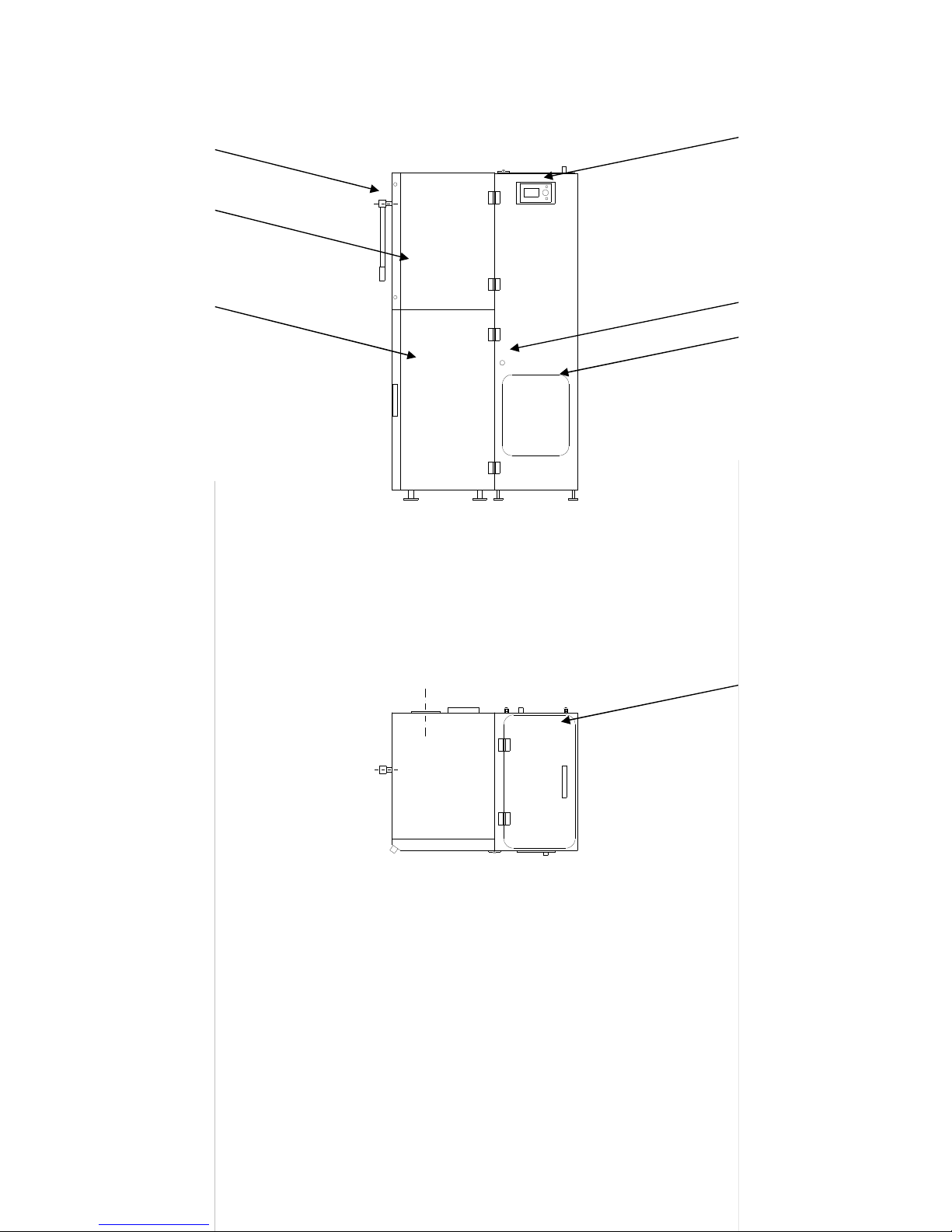
Front view
Top view
Fig. 2. Schema of the Smart Fire boiler
1 - display; 2 - thermostat reset (under the plastic cap); 2- inspection hole of the controller; 4 - fuel
container clap door 5 -knob of the heat exchange cleaner; 6 - heat exchange covering panel;
7- boiler door cover;
Instrukcja Smart Fire wer. 07/05/2010/ENG
HKS LAZAR str.9
2
4
5
3
6
7
1
 Loading...