

Page 1
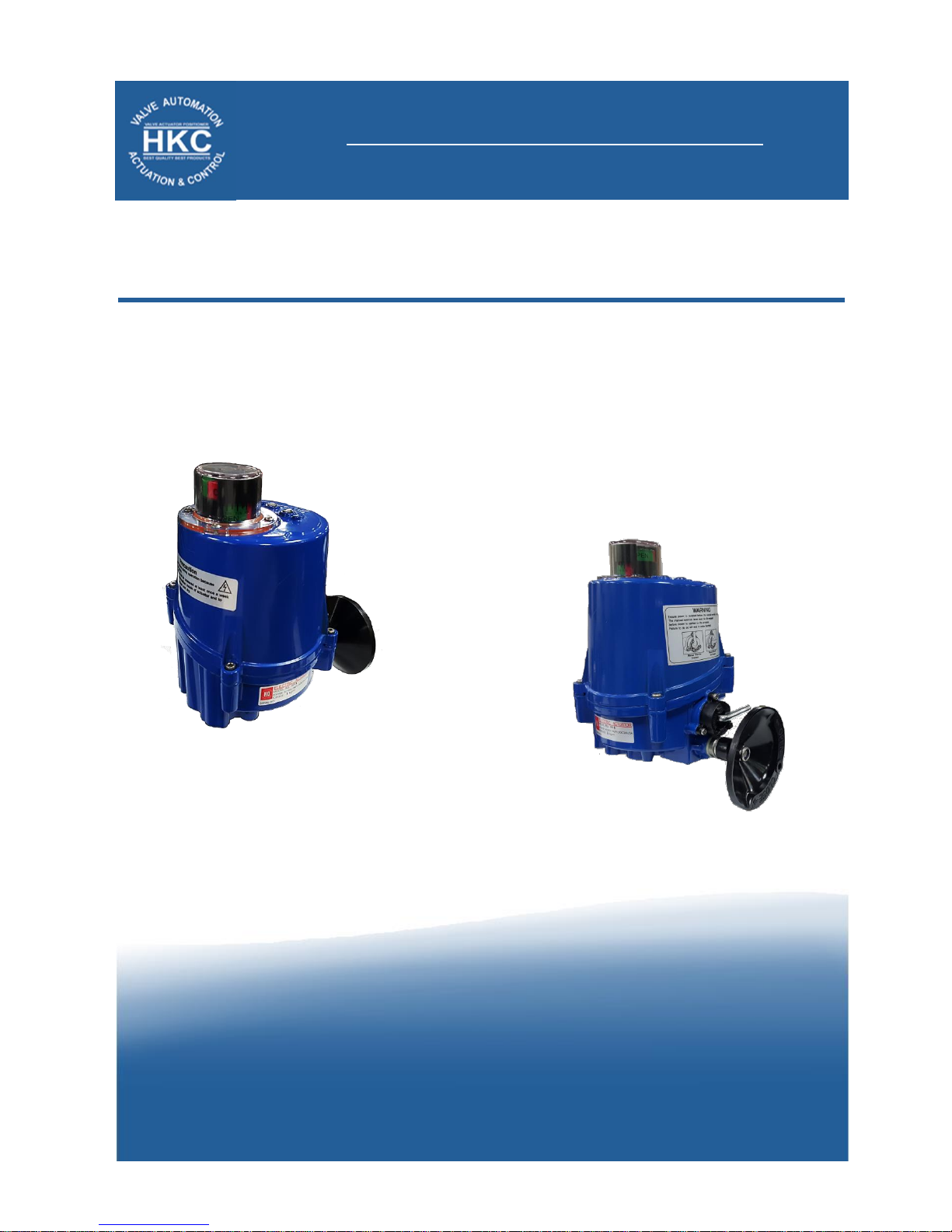
Installation, Operation and Maintenance Manual
HQ – 005. ELECTRIC ACTUATORS
QUARTER-TURN ELECTRIC ACTUATORS
HQ-005 Electric Actuators
Version – Ver. 1
Revision – Rev. 3
Document No. HKQI-611
Actuated Solutions Ltd
Unit 9, Evans Place, Durban Road, Bognor Regis, West Sussex, PO22 9RY
Website: www.actuated-solutions.co.uk
Small & Compact Design
High corrosion resistance
Beacon indicator with LED lamps
IP67 Weatherproof Aluminium housing
Multi-voltage Power Supply
Long life cycle
Page 2

Table of Contents
1 INTRODUCTION ................................................................................................................ 1
1.1 Purpose .................................................................................................................................. 1
1.2 Safety Notices ........................................................................................................................ 1
2 PRODUCT IDENTIFICATION ............................................................................................. 2
2.1 Product Identification ............................................................................................................ 2
2.1.1 Marking ............................................................................................................................................... 2
2.2 Initial Inspection .................................................................................................................... 2
2.3 Storage ................................................................................................................................... 2
3 GENERAL INFORMATION AND FEATURES .................................................................... 3
3.1 General Information .............................................................................................................. 3
3.1.1 Performance ....................................................................................................................................... 3
3.1.2 Standard Technical Data ..................................................................................................................... 3
3.1.3 HQ-005 Optional Technical Data (Optional) ....................................................................................... 3
3.1.4 Duty Cycle 1) ........................................................................................................................................ 3
3.1.5 Torque Control ................................................................................................................................... 4
3.1.6 Manual Override................................................................................................................................. 4
3.1.7 Lubrication .......................................................................................................................................... 4
3.2 External Parts for Standard Models ...................................................................................... 5
3.3 Internal Parts for Standard Models ....................................................................................... 5
4 INSTALLATION .................................................................................................................. 6
4.1 Pre-installation for using in General Service ......................................................................... 6
4.2 Actuator Mounting ................................................................................................................ 6
4.2.1 Actuator Mounting Base Details ........................................................................................................ 7
4.3 Limit Switch Setting ............................................................................................................... 8
5 MAINTENANCE ................................................................................................................. 9
5.1 Maintenance .......................................................................................................................... 9
5.2 Tools ....................................................................................................................................... 9
6 TROUBLE SHOOTING .................................................................................................... 10
7 DIMENSIONS ................................................................................................................... 12
Page 3

Installation, Operation and Maintenance Manual
HQ-005 Electric Actuator
Document No. HKQI-611
1 | P a g e
1 INTRODUCTION
1.1 Purpose
The purpose of this manual is to introduce and explain the installation, operation and maintenance of HQ-005
electric actuators.
A copy of all wiring diagrams can be found online at our website
www.actuated-solutions.co.uk
1.2 Safety Notices
Safety notices in this manual outline precautions the user must take to reduce the risk of personal injury and
damage to the equipment. The user(s) must read these instructions before the installation, operation or
maintenance of HQ-005 electric actuators.
DANGER: Refers to personal safety and alerts the user to danger or harm.
The hazard or unsafe practice will result in severe injury or death.
WARNING: Refers to personal safety. Alerts the user to potential danger.
Failure to follow warning notices could result in personal injury or death.
CAUTION: Directs the user’s attention to general precautions that, if not
followed, could result in personal injury and/or equipment damage.
Page 4

Installation, Operation and Maintenance Manual
HQ-005 Electric Actuator
Document No. HKQI-611
2 | P a g e
2 PRODUCT IDENTIFICATION
2.1 Product Identification
The actuator name plate is located on the opposite side of the conduit entry. The name plate contains the
following:
2.1.1 Marking
A) General
HQ logo (trade mark)
Model
Torque
Electrical power supply
Type
Rated current
Operating time (seconds)
Serial No.
Option
2.2 Initial Inspection
Upon on the receipt of the actuator, the user should inspect the condition of the product and ensure that
product specification stated in the name plate matches with the order sheet.
Remove the packing wrap or wooden box carefully. Inspect the product for any physical damage
that may have occurred during shipment.
Check the product specification with product ordered. If a wrong product has been shipped,
immediately report to our coordinator.
2.3 Storage
Actuators must be stored in a clean, cool and dry area. The unit should be stored with the cover installed and
the conduit openings sealed. Storage must be off the floor, covered with a sealed dust protector. When
actuators are to be stored outdoor, they must be stored off the ground, high enough to prevent from being
immersed in water or buried in snow.
ELECTRIC ACTUATOR
Q U A R T E R T U R N E L E C T R I C A C T U A T O R
MODEL : HQ-005
POWER:AC95-265V,24VAC/DC
OPERATION TIME: SEC.
SERIAL NO:
TORQUE: 5Kgf.m
TYPE: ON-OFF
RATED CURRENT : A
OPTION:
Page 5

Installation, Operation and Maintenance Manual
HQ-005 Electric Actuator
Document No. HKQI-611
3 | P a g e
3 GENERAL INFORMATION AND FEATURES
3.1 General Information
HQ-005 electric actuators are designed for the operation of small size quarter turn valves; e.g. ball, butterfly and
damper valves etc. with high reliability and efficiency.
3.1.1 Performance
Type
Max.
output
Torque
Operating
time(sec.)
Duty Cycle
IEC34-1
Mounting
Size
Power
1 Phase
Rated Current (A) 60/50 Hz
Weight
AC
DC/AC
Kg.m
90°
S4 (%)
ISO 5210
AC or DC
110V
220V
24V
kg
HQ-005 5 13
70
F03, F04, F05
F07
95V ~ 265V AC
or
24V DC/AC
1A
0.5A
0.8A
1.2
3.1.2 Standard Technical Data
3.1.3 Optional Technical Data (Optional)
3.1.4 Duty Cycle 1)
Duty cycle rated IEC60034 – S4 70%
Exceeding the actuator’s rated duty cycle may cause thermal overload.
Note:
1)
Type of duty according to VDE 0530 / IEC 60034-1
Enclosure Rated
Weatherproof IP67
Enclosure
High grade aluminum alloy, corrosion resistant coated
Power Supply
110 / 220V AC 1 Ph 60/50Hz
24 V DC/AC
Duty Type
S4 70% / S2 30min (IEC 60034)
Motor
BLDC motor
Limit Switches
2 x open/close SPDT, 250V AC 5A rating
Auxiliary Limit Switches
2 x open/close SPDT, 250V AC 5A rating
Indicator
Continuous position indicator & full position LED lamp
Manual Override
Manual Handwheel
Lubrication
Grease moly EP
Ambient Temperature
-20 ℃~ + 80 ℃
External Coating
Dry powder polyester
TS
Torque overload indicator via flashing LED indication
PIU
Potentiometer Unit (0~1KΩ)
PCU
Proportional Control Unit (input, output 0~10V DC, 4~20mA DC)
CPT
Current Position Transmitter (output 4~20mA DC) , 0~10V
Short – time duty S2
Intermittent duty S4
The operation time at a constant load is short,
so that thermal equilibrium is not reached.
The pause is long enough for the machine to
cool down to ambient temperature. The
duration of the short –time operation is limited
to 15min (10min, 30min)
The duty is a sequence of identical cycles
which consist of starting time, operation time
with constant load and rest period. The rest
period allows the machine to cool down so
that thermal equilibrium is not reached. The
relative on-time at S4-25% or S4-50% is
limited to 25% and 70% respectively.
Page 6
Installation, Operation and Maintenance Manual
HQ-005 Electric Actuator
Document No. HKQI-611
4 | P a g e
3.1.5 Torque Control
Torque sensor which detects the variation of torque during operation is installed for preventing damage of valve
and actuator under overload condition. Once actuator is under overload, torque sensor is tripped and actuator
stopped immediately
(This is standard when the actuator is fitted with PCU & is an option of on/off control)
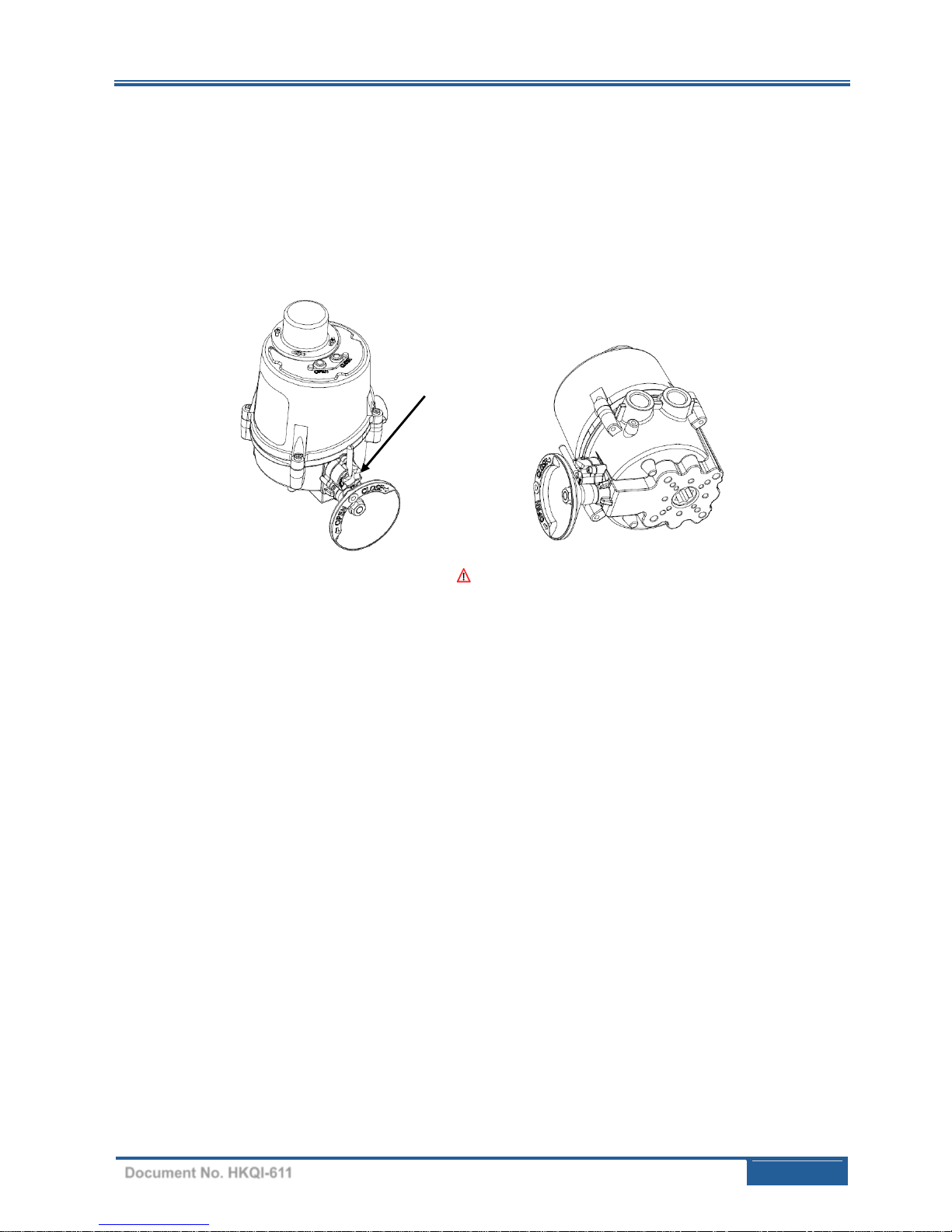
3.1.6 Manual Override
Caution
Ensure power is isolated before the manual override is engaged.
The manual override lever must be dis-engaged before power is applied to the actuator.
Failure to do so will end in motor burnout.
Gently oscillate the handwheel while engaging & disengaging the manual override lever.
The lever in vertical position = Engaged
The lever in horizontal position = Dis-engaged
3.1.7 Lubrication
HQ-005 electric actuator is a totally enclosed unit with permanent lubricated gear train (Moly EP Grease). Once
installed, further lubrication should not be required. However, periodic preventative maintenance will extend
the operating life of the actuator.
(1) Manual Handwheel
Page 7
Installation, Operation and Maintenance Manual
HQ-005 Electric Actuator
Document No. HKQI-611
5 | P a g e
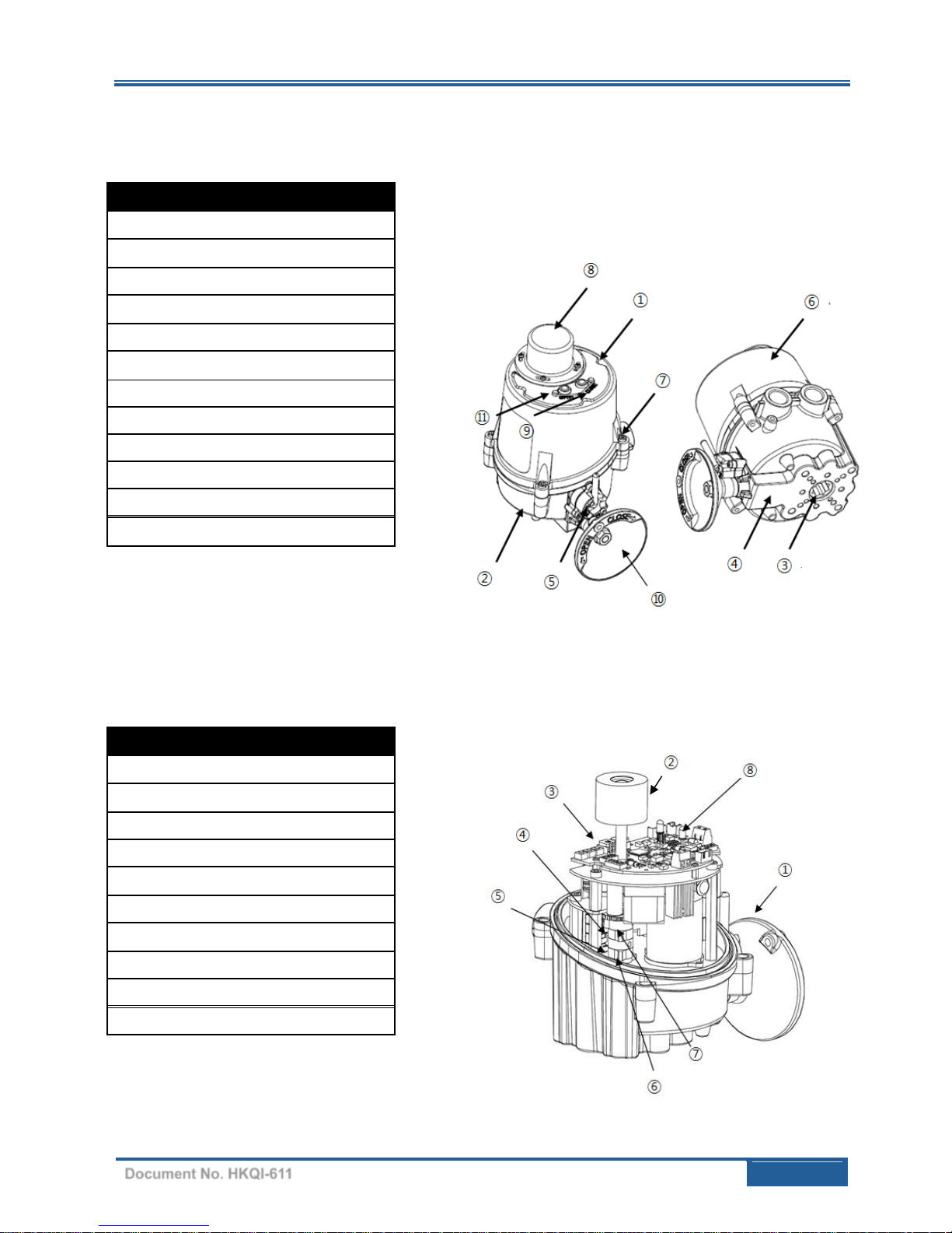
3.2 External Parts for Standard Models
3.3 Internal Parts for Standard Models
External Parts
HQ-005
1
Top Cover
2
Body
3
Star drive (double square 14mm)
4
Mounting base (F03, F04, F05,F07)
5
Manual lever
6
Name Plate
7
Captive cover bolt
8
Beacon Indicator
9
Fully closed LED lamp (red color)
10
Manual hand wheel
11
Fully open LED lamp (green color)
Internal Parts
HQ-005
1
Manual push shaft
2
Indicator
3
PCB
4
Auxiliary Open Switch (White)
5
Closed limit switch (Green)
6
Open limit switch (Red)
7
Auxiliary Closed Switch (Black)
8
Fully closed LED lamp (Red)
9
Fully open LED lamp (Green)
①
②
①
Page 8

Installation, Operation and Maintenance Manual
HQ-005 Electric Actuator
Document No. HKQI-611
6 | P a g e
4 INSTALLATION
4.1 Pre-installation for using in General Service
Verify the actuator’s nameplate to ensure correct model number, torque output, operating speed, voltage and
enclosure type before installation or use.
It is important to verify that the torque output of the actuator is appropriate for the torque requirements of the
valve and that the duty cycle of the actuator is appropriate for the intended application.
4.2 Actuator Mounting
Note:
Prior to mounting, the actuator must be checked for any damage
Damaged parts must be replaced by original spare parts
Mounting is most easily done with the valve shaft pointing vertically upward. But mounting is also possible in
any other position; the actuator may be mounted in any position.
WARNING:
Read this installation, operation and maintenance manual carefully and
completely before attempting to install, operate, or troubleshoot the
actuator.
CAUTION:
Do not attempt to work on your HQ005 actuator without first shutting off
the incoming power
Do not attach ropes or hooks to the hand wheel for the purpose of lifting
by hoist
Page 9
Installation, Operation and Maintenance Manual
HQ-005 Electric Actuator
Document No. HKQI-611
7 | P a g e
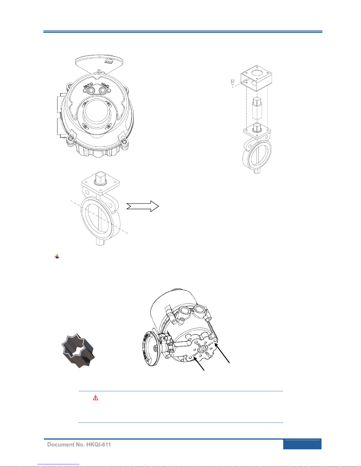
4.2.1 Actuator Mounting Base Details
Note:
Make sure both the actuator and valve are fully closed.
DANGER:
HAZARDOUS VOLTAGE. Make sure all incoming power is disconnected
before performing the mounting.
Direct Mounting
(ISO Standard)
Actuator: Fully Closed
Valve: Fully Closed
Bracket Mounting
Actuator Mounting Base: F03/F04/F05/F07
F04 Bolt Circles (45°)
F03, F05, F07 Bolt Circles
Star Adapter
14mm→11mm
14mm→9mm
Page 10
Installation, Operation and Maintenance Manual
HQ-005 Electric Actuator
Document No. HKQI-611
8 | P a g e
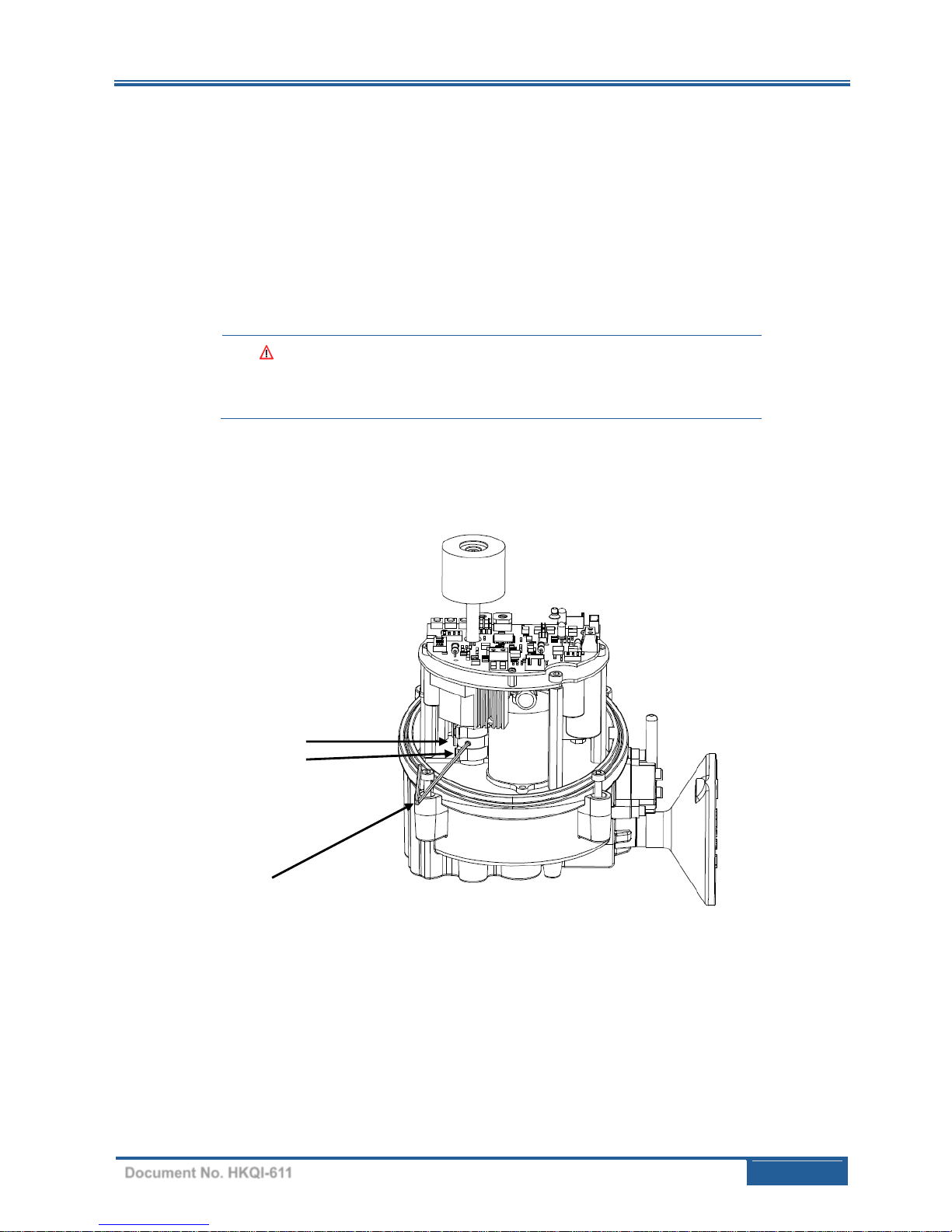
4.3 Limit Switch Setting
Manually rotate the hand wheel of the actuator to fully closed position
Using a Allen key, loosen the set screw in the CLOSE limit switch cam
Rotate the CLOSE cam towards CW limit switch lever until the switch ‘clicks’
Tighten the set screw with the Allen key
Manually rotate the hand wheel of the actuator to opened position
Using the Allen key, loosen the set screw in the OPEN limit switch cam
Rotate the OPEN cam towards CCW limit switch lever until the switch ‘clicks’ (see Figure below)
Tighten the set screw with the Allen key
DANGER:
HAZARDOUS VOLTAGE. Make sure all incoming power is disconnected
before setting the limit switch
Open Limit Switch Cam (CCW)
Open Limit Switch
2mm Allen key
Page 11

Installation, Operation and Maintenance Manual
HQ-005 Electric Actuator
Document No. HKQI-611
9 | P a g e
5 MAINTENANCE
5.1 Maintenance
Under the normal conditions, maintenance should be carried out at six month intervals. But when the
conditions are more severe, more frequent inspections may be advisable.
Ensure that the actuator is properly aligned with the valve or other actuated device
Ensure that all wirings are insulated, connected and terminated properly
Ensure that all screws are present and tight
Ensure cleanness of internal electrical devices
Ensure that conduit connections are properly installed and are dry
Check the internal devices for any condensation
Check the enclosure of O-ring seals and verify that the O-rings are not pinched between flange
Verify the declutch mechanism
Visually inspect the open/close cycle
Inspect the identification labels for wear and replace it if necessary
5.2 Tools
Metric Allen Key (Hex Wrench) × 1
Screw Driver × 1
Metric Spanner × 1
Wrench 200mm × 1
Wrench 300mm × 1
Wire Stripper Long Nose × 1
Multi-meter (AC, Dc, Resistance) × 1
PCU Board Option: DC Signal Generator (4 – 20mA DC) × 1
PCU & CTU Board Option: 1mA Ammeter (0 – 25mA)
CAUTION:
Turn off all power before attempting to perform maintenance on the
actuator.
POTENTIALLY HIGH PRESSURE VESSEL. Before removing or
disassembling your actuator, ensure that the valve or other actuated
device is isolated and not under pressure.
WARNING:
Treat cover with care. Gap surfaces must not be damaged or dirtied in
any way. Do not jam the cover during fitting.
Page 12

Installation, Operation and Maintenance Manual
HQ-005 Electric Actuator
Document No. HKQI-611
10 | P a g e
6 TROUBLE SHOOTING
The following instructions are listed in the order of the most common difficulties encountered during the
installation and start-up.
! The actuator does not respond
Visually inspect the actuator to check no shipping or handling damage has occurred
Verify the line voltage supplied to the actuator; check that the line voltage matches with the rating on
the actuator’s nameplate
Check the internal wiring against the supplied wiring diagram of the actuator (copy of which can be
found on our website)
Check the limit switch cams
! The actuator is supplied with power but does not operate
Verify the line voltage supplied to the actuator; check that the line voltage matches with the rating on
the actuator’s nameplate.
Check that the actuator torque is greater than the valve torque
Check the limit switch cams
Check that the torque switches have not been tripped
Check the mechanical travel stop adjustment
Verify that the actuator against the rotation of the valve (standard units are counter-clockwise rotation
to open)
Check for any corrosion and condensation that any of the electrical or mechanical devices have not
been contaminated
Verify that coupler/bracket is correctly installed and is not causing any binding
! Actuator runs erratically
Check the ambient temperature
Verify that the duty cycle has not been exceeded
Check the position of manual override lever
Symptom
Probable Cause
Corrective Action
Motor will not run
Open in control circuit
Refer to appropriate wiring diagram and check
for continuity
Insulation resistance breakdown
in motor
Perform megger Test
No power available to actuator
Tripped circuit breaker
Reset circuit breaker
Manual Override hard to turn
Valve stem improperly lubricated
Lubricate with grease
Clean out old grease and replace with
recommended lubricant
Actuator lubrication has broken
down
Valve packing gland too tight
Loosen packing gland nuts as necessary
Jammed valve
Refer to valve maintenance
Valve only opens or closes
partially with motor
Limit switch improperly set
Check setting and reset if necessary
Manual Override Nut will not
operate valve
Stripped gearing
Replace as necessary
Broken hand wheel shaft
Replace as necessary
Broken valve stem
Repair or replace as necessary
Motor runs but will not operate
valve
Stripped gearing
Replace as necessary
Page 13

Installation, Operation and Maintenance Manual
HQ-005 Electric Actuator
Document No. HKQI-611
11 | P a g e
! Optional Equipment(s)
1) Potentiometer Current Position Transmitter
Check the resistance value
Check potentiometer gear for jamming
Check ZERO and SPAN calibration
Check the board for any damage
2) PCU – Positioner card
Verify the input signal
Check the configuration of the dip switches
Check the board for any damage
Page 14
Installation, Operation and Maintenance Manual
HQ-005 Electric Actuator
Document No. HKQI-611
12 | P a g e
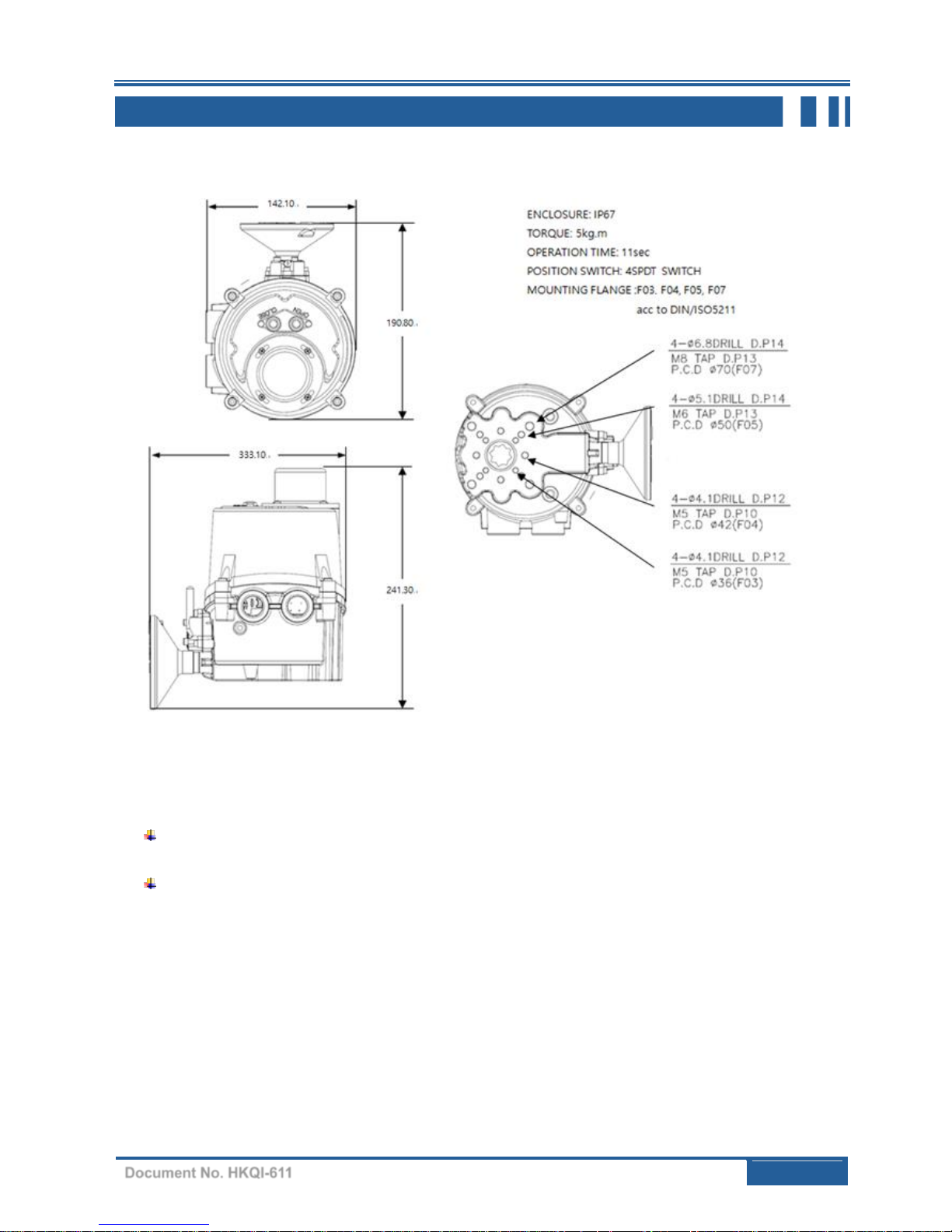
7 DIMENSIONS
Note:
For more information regarding this product, please contact the manufacturer or your supplier for
more details.
Please refer to the website for the latest wiring diagrams.
 Loading...