

HKC Co HM04, HM11, HM20, HM, HM08 Installation And Maintenance Manual
...
Installation and Maintenance Manual
HKC
HM-SERIES / ACTUATORS
Version- V1
Document No. HQOI-08-EV1
DATE : 2011.12.22
H K C
WWW.HKCON.CO.KR
HKC CO.,LTD.
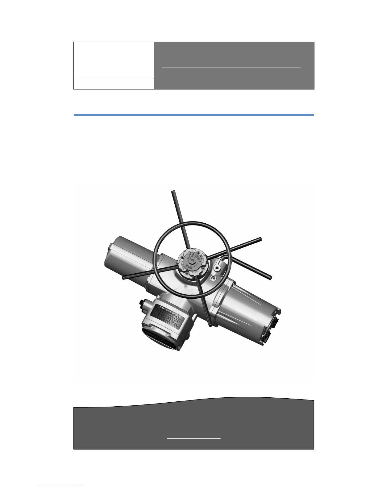
HM – Series. ELECTRIC ACTUATORS
INTELLIGENT MULTI-TURN ELECTRIC ACTUATORS
VALVE AUTOMATON

HHMM--SSeerriieess EElleeccttrriicc AAccttuuaattoorr
IInnssttaallllaattiioonn aanndd OOppeerraattiioonn MMaannuuaall
HHKKC
C
2
1. Introduction
1.1 Purpose 3
1.2 Manual Guidelines contents 3
1.3 External Parts for Standard Models 4
1.4 Safety Notices 4
2. Product Identification
2.1 Product Identification 6
2.1.1 Marking 6
2.2 Initial inspection 7
2.3 Storage 7
3. General Information and Features
3.1 General 7
3.2 Performance Data 8
3.2.1 AC 3 Phase Model & Torque (Nm) 8
3.2.2 AC 1 Phase Model & Torque (Nm) 8
3.2.3 Solid state design Model & Torque (Nm) 9
3.2.4 Mechanical Data 9
3.3 HM Standard Technical Data (Standard) 10
3.4 HM Option Technical Data (Optional) 11
3.5 Duty Cycle 11
3.6 Hand wheel and Declutching 11
3.7 Lubrication 12
3.8 Internal Parts for Standard Models 13
4. Installation and operation instruction
4.1 Pre-installation for use in general service 14
/ potentially explosive atmosphere
4.2 Actuator Mounting 14
4.3 Actuator Mounting Details (ISO5211 & 5210) 15
4.3.1 Mounting base 15
4.3.2 Disassembly and Assembly of Mounting Base 16
4.3.3 Disassembly and Assembly the Drive Bush in Thrust Base 17
4.3.4 Disassembly and Assembly the Drive Bush in Non-Thrust Base 18
4.4 Electrical Connections and Preliminary Test 18
5. Maintenance
5.1 Maintenance 20
5.2 Tools 20
6. Trouble shooting 21
7. Installation and maintenance tips 22
8 . Wiring Diagram
8-1~3. HM-Standard 3ph, CPT,PCU 23~25
9. Dimension 26
10. Grounding 27
APPENDIX I : HM-series Coding System 28

1
Introduction
1.1 Purpose
This Installation and operating manual
Multi -Turn
electric actuators.
There is no need for removal of the outer casing (exclude wiring), when operating t
HM Multi -
Turn electric actuator, due to its
The terminals for wiring and the internal electronics are sealed tight hence allowing
for unhindered removal procedures
When setting up the a
restrictions and
etc as they are individually displayed on screen
reduce the risk of danger as setup can be remotely carried out at a safer distance
The help menus for the control system of the valve and
screen hence user friendly
Configuration, alarm and status tests are given in English (default)
Movement of valve torque position values for the
1.2 Manual Outline
•
Electrical
•
Actuator
•
Basic configuration setup and actuation walkthroughs
•
Specific on
•
Maintenance and troubleshooting
•
Sales and A/S information
This manual contains important safety information
It is emphasized that the user understands the following material given in this document
before installation and setup of any product before operation and maintenance.
HHMM--SSeerriie
ess
IInnssttaallllaattiioonn aanndd
O
O
explains how to install, operate and maintain
Smart Intelligent
electronic
actuat
.
ctuator
utilize the remote control to set the torque,
.
This feature may
Actuator
are ava
.
.
actuator
is displayed on screen
IP 68 Design
and manual (local or remote) operation procedures
or Valve installation guidelines
-site and custom control requirement tasks
.
EElleeccttrriicc AAccttuuaattoorr
ppeerraattiioonn MMaannuuaall
HHKKC
C
3
the HM
he
ion capability
.
limit switches,
.
ilable on
.
HHMM--SSeerriieess EElleeccttrriicc AAccttuuaattoorr
IInnssttaallllaattiioonn aanndd OOppeerraattiioonn MMaannuuaall
HHKKC
C
4
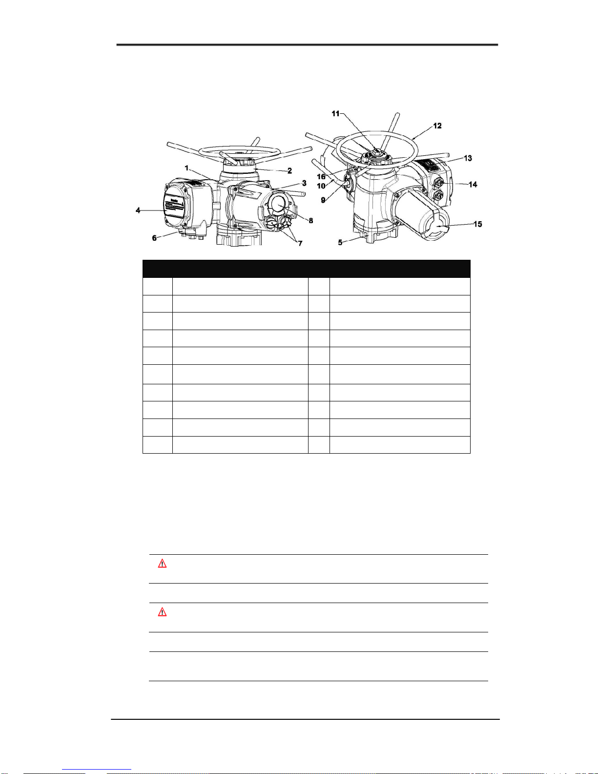
1.3 External Parts for Standard Models
1.4 Safety Notices
Safety notices throughout this manual detail precautions the user must take to reduce the risk
of personal injury and damage to the equipment. The user must read these instructions before
installation, operation or maintenance.
DANGER : Refers to personal safety. Alerts the user to danger or harm.
The hazard or unsafe practice will result in severe injury or death.
WARNING : Refers to personal safety. Alerts the user to potential danger.
Failure to follow warning notices could result in personal injury or death.
CAUTION : Directs the user’s attention to general precautions that, if not followed,
could result in personal injury and/or equipment damage.
External Parts
1 Body 11 Top Handle Cover Name Plate
2 Top Handle Cover 12 Hand wheel
3 Control Cover 13 Name Plate
4 Terminal Cover 14 Cable Plug
5 Mounting Base 15 Motor
6
Conduit Entries
(NPT 1”x4EA, 11/2”x1EA)
16 Grease Plug
7 Control Knob
8 Window & Indicator
9 Lever Supporter
10 Hand/Auto Lever
HHMM--SSeerriieess EElleeccttrriicc AAccttuuaattoorr
IInnssttaallllaattiioonn aanndd OOppeerraattiioonn MMaannuuaall
HHKKC
C
5
Note : Read carefully the following information as it is critical to the user’s understanding of the
actuator installation and operation procedures. This manual contains important safety
information. Please ensure it is thoroughly read and understood before installing, operating
or performing maintenance procedures for equipment.
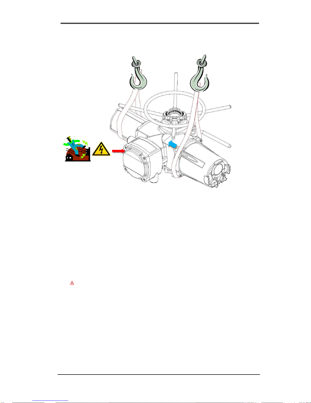
CAUTION
1. Do not open cover during operation
in case of electrical shock
This manual contains critical information related to the operation of the
HM
series
Actuators
. It
is crucial that only trained personnel who understands thoroughly the setup, operations,
controls and inspection procedures due to safety concerns. Follow the manual guidelines
before setup. When misused, the Actuator can cause harm, severe injury or even death due
to high voltages and forces involved. It is highly recommended to request for training prior to
use.
Take extreme care when operating environments exceeds the range of -20°C~80°C. The
Actuator is intended to operate between the given ranges on the nameplate of each actuator.
In the case where products are exposed to temperature ranges that exceed the allowed
range, do not check for damage as it could result in severe injury. Consult with the
manufacturer as soon as possible. Do not attempt to alter the Actuator physically as this
could lead to leakage and malfunction of the product. Before performing maintenance in
potentially hazardous areas, make sure all electrical supplies are shutdown and actuator
relocated to an environmentally safe location.
WARNING
Housing Material:
Up to the HM010~035 of the
HM-Series
, Aluminium is processed
to manufacture the housing. Bolts etc are manufactured of stainless steel and base
from Cast Iron. The Models from HM40 ~ IQ90 are a mixture of Aluminium and
Ductile Iron. Before operating an
Actuator
the user must verify environmental
compatibility to avoid chemical corrosion. Study to determine safety must be
conducted before use.
Self-heating motor temperature:
In normal operation mode the temperature of the
Actuator cover may exceed 60⁰C and advise great caution when handling.
Motor thermal protection (By Pass):
Whenever the configurations are set to
bypass the Actuator cover temperature, any Hazardous area handling certificates
becomes invalid. Keep in mind hen using this mode that the risk of electrical danger
increases. The user must
measures.
Actuator manual operation
follow as directed.
In remote mode, the Actuator can be controlled to be switched on and off.
2
Product
Identification
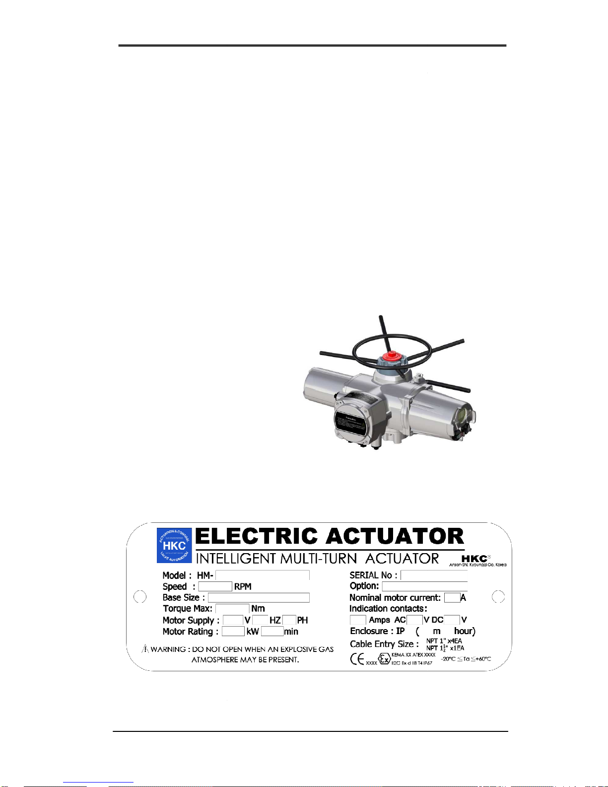
2.1
Product Identification
The
actuator name plate is located on the
plate contains the following
2.1.1
Marking
a) General
HQ logo
(trade mark)
Model
Speed
Base Size
Torque Max
Motor supply
Motor Rating
Option
Serial No.
Nominal Motor current
Indication contacts
Enclosure
Name of manufacturer and country shall not be printed based on OEM
HHMM--SSeerriie
ess
IInnssttaallllaattiioonn aanndd
O
O
utilize
protective equipment and take additional safety
:
Read the manual operation
section carefully and
side of the opposite of
the conduit entry. The name
information.
EElleeccttrriicc AAccttuuaattoorr
ppeerraattiioonn MMaannuuaall
HHKKC
C
6
.

HHMM--SSeerriieess EElleeccttrriicc AAccttuuaattoorr
IInnssttaallllaattiioonn aanndd OOppeerraattiioonn MMaannuuaall
HHKKC
C
7
2.2 Initial inspection
When the inspecting the actuator, check the product for damage and ensure the name plate
concurs with the order sheet.
Remove packaging wrap or wooden box carefully. Inspect the product for any
physical damage that may have occurred during shipment.
Check the product specification with product ordered. If an incorrect product has
been shipped, immediately report the issue to our coordinators.
2.3 Storage
Actuators must be stored in a clean, cool and dry area. The unit shall be stored with
the cover installed and the conduit openings sealed. Storage must be off the floor,
covered with a sealed dust protector. When placing an Actuator outdoors, they must
be stored off the ground, high enough to prevent being immersed in water or buried
in snow. If the Actuator cannot be placed immediately, make sure to store it in a dry
area. It is recommended that if the Actuator cables cannot be installed immediately
use the plastic plug with PTFE tape to block/seal where the metal plugs are located.
When sealed correctly, the internal electronics are preserved from external corrosion
for extended periods of time (up to 1 year). Note that there is no need, when working
on the Actuator, to remove any electronics. If the control cover is removed, the
warranty may be void. Each individual Actuator will be tested before delivered hence,
given instructions have been correctly followed, setup and operation should be
smooth.
3
General Information and Features
3.1 General
HM series electric multi-turn actuators
are controlled via the Smart Intelligent actuator
system and suitable for various industrial plants such as ship construction, power
plants, petrochemical semiconductor plants and many other high-end industrial
uses. Additionally, depending on the specific application, 9 different models are
available.
HM-04,08,011,020,040,060,100,150,200,300

HHMM--SSeerriieess EElleeccttrriicc AAccttuuaattoorr
IInnssttaallllaattiioonn aanndd OOppeerraattiioonn MMaannuuaall
HHKKC
C
8
3.2 Performance Data
3.2.1 AC 3Phase Model & Torque(Nm)
RPM
MODEL & TORQUE(Nm)
3Phase
50HZ 60HZ HM04 HM08 HM11 HM20 HM40 HM 60 HM100 HM150 HM200 HM300
18 21 35 80 110 200 400 600 1000 1500 2000
24 29 35 80 110 200 400 600 1000 1500 2000 3000
36 43 35 80
200 300 540 850 1300 1700
48 57 35 68
200 250 470 680 1000 1360
72 86 35 48
176 250 470 680 1000 1360
96 115 35 40
142 230 370 540 750 1000
144 173
105 150 260 400 650 860
192 230
540 730
3.2.2 AC 1Phase Model & Torque(Nm)
RPM
MODEL & TORQUE(Nm) 1Phase
AC110~220V (HM040 은 220V 이상)
50HZ 60HZ HM04 HM08 HM11 HM20 HM40 HM 60 HM100 HM150 HM200 HM300
18 21 - 65 - 165 450
- - - - -
24 29 - 60 - 130 400
- - - - -
36 43 - 45 - 130 350
- - - - -
48 57 - 40 - 125 320
- - - - -
72 86 - 30 - 100 230
- - - - -
96 115
- 25 - 80 190
- - - - -
144 173
- - - 60 135
- - - - -
192 230
- - - - - - - - - -
*(RED) At high speeds, do not operate without a GEAR BOX mechanism as this may result in problems!
*Maximum torque for actuator is shown. (BLUE) Operation for AC 220V or over have been outlined.

HHMM--SSeerriieess EElleeccttrriicc AAccttuuaattoorr
IInnssttaallllaattiioonn aanndd OOppeerraattiioonn MMaannuuaall
HHKKC
C
9
3.2.3 Solid state design Model & Torque(Nm)
RPM
MODEL & TORQUE(Nm)
Solid state type 3Phase (AC380V~)
50HZ 60HZ HM04 S3 HM08 S3 HM11 S3 HM20 S3 HM40 S3
18 21 35 80 110 200 400
24 29 35 80 110 200
36 43 35 80
48 57 35 68
72 86 35 48
RPM
MODEL & TORQUE(Nm)
Solid state type 1Phase
50HZ 60HZ
HM08 S1
(AC110~240V)
HM20 S1
(AC220~240V)
18 21 65 165
24 29 60 130
36 43 45 130
48 57 40 125
72 86 30 100
96 115
25 80
3.2.4 Mechanical Data
Mechanical Data
MODEL
HM04 HM08 HM11 HM20 HM40 HM60 HM100 HM150 HM200 HM300
Flange size(ISO5211)
F10 F10 F10 F14 F14 F16 F25 F30 F25 F30
Weight
30 30 30 65 65 70 190 190 200 200
Thrust rating(Nm)
44 44 44 100 100 150 220 220 334 445
Stem acceptance diameter maximum size
(BASE) unit: mm
Thrust
Rising
32 32 32 38 38 54 64 70 70 83
Non-rising
26 26 26 32 32 45 51 57 57 73
Non
large type
42 42 42 60 60 80 100 100 120 120
Thrust
ISO type
20 20 20 30 30 40 50 50 50 N/A
blank type
20 20 20 30 30 44 50 60 60 N/A
Hand wheel ratio
Direct Direct Direct Direct Direct Direct Direct
18:1 18:1 18:1
Option
15:1 15:1 15:1 15:1 15:1 23:1 54:1 54:1 54:1 54:1
Cable entry
STANDARD PF 1”x 4EA PF 1½”x1 OPTION NPT 1”x 4EA NPT 1½”x1
 Loading...