

HKC Co APL-8 Installation, Operation & Maintenance Manual
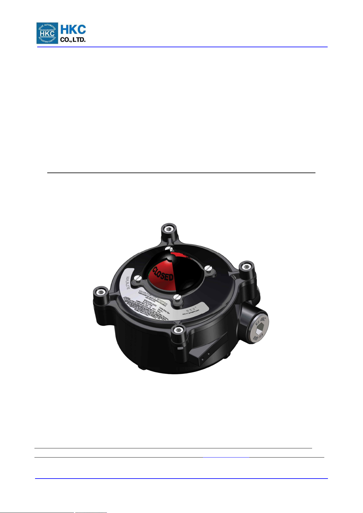
APL-8 Series Limit Switch Box
Installation Operation & Maintenance Manual
Doc No. : HUMG-APL8-16 Rev0 Page 1 / 12 Valve Automation Leader, HKC
APL-8 Series Valve Position Monitor
Installation, Operation & Maintenance Manual
Address : Seonggok-dong, 155, Byeolmang-ro, Danwon-gu, Ansan-si, Gyeonggi-do, South Korea
Tel : +82 -31-488-8266, Fax : +82 -31-488-8269, Home page : www.hkcon.co.kr , email : hkcon@hkcon.co.kr

APL-8 Series Limit Switch Box
Installation Operation & Maintenance Manual
Doc No. : HUMG-APL8-16 Rev0 Page 2 / 12 Valve Automation Leader, HKC
Table of Contents
1. General ...................................................................................................................... 3
2. Ordering Information ................................................................................................. 3
3. Standard specification ............................................................................................... 3
4. Preparing for Installation ............................................................................................ 4
4.1. Marking ..................................................................................................................... 4
4.2. Pre-Installation for use in potentially explosive atmosphere....................................... 4
5. Standard Features ..................................................................................................... 5
6. Installation ................................................................................................................. 5
6.1. Mounting bracket .............................................................................................. 5
6.2. Mounting limit switch box.................................................................................. 6
6.3. Setting cam ....................................................................................................... 6
6.4. Wiring ............................................................................................................... 7
6.5. Setting Position Transmitter Unit (APL- 8 . 6) .................................................. 10
7. Maintenance ............................................................................................................ 10
8. Inspection ................................................................................................................ 11
9. Storage .................................................................................................................... 11
10. Trouble Shooting ..................................................................................................... 11
11. Tools ........................................................................................................................ 11
12. Installation and Maintenance Tips ............................................................................ 11

APL-8 Series Limit Switch Box
Installation Operation & Maintenance Manual
Doc No. : HUMG-APL8-16 Rev0 Page 3 / 12 Valve Automation Leader, HKC
1. General
1.1. HKC APL series limit switch box is designed to provide accurate and reliable valve position signaling and
indicating of most valves or actuators manufactured.
1.2. APL limit switch box consists of a visual position indicator, quick-set cam ass’y, terminal strip, switch ass’y
and easy mounting bracket. Quick-set cam allows for a quick and simple hand operation in the setting of
switches.
2. Ordering Information
APL - 8 1 0 N
① ② ③
① Enclosure type of flame proof is based on IECEx EPS 13.0043X:
Ex d IIC T 6 Gb
Enclosure type of flame proof is based on ATEX EPS 14 ATEX 1 695 X:
II 2 G Ex d IIC T 6 Gb
Enclosure type of flame proof is based on
KCs
15-AV2BO-0650X
: Ex d IIC T6 Gb
② Switch type
10 : 2-SPDT (Wonwoo : SZM-V16-5FA-61)
11 : 3-SPDT (Wonwoo : SZM-V16-5FA-61)
12 : 4-SPDT (Wonwoo : SZM-V16-5FA-61)
13 : 2-SPST (Wonwoo : SZM-V16-5FA-61)
14 : 2-DPDT (Omron : DZ-10GW-1B)
15 : 2-SPDT + Potentiometer (Wonwoo : SZM-V16-5FA-61)
16 : 2-SPDT + Signal Unit(4~20mA) (Wonwoo : SZM-V16-5FA-61)
20 : Proximity Sensor (P&F : NJ2-V3-N)
21 : Proximity Sensor (Autonics : PS17-5DNU)
23 : Proximity Sensor (P&F : NBB2-V3)
25 : Proximity Sensor (P&F : NJ2-V3-N) + Potentiometer
26 : Proximity Sensor (P&F : NJ2-V3-N) + Signal Unit (4~20mA)
30 : Reed type Proximity Sensor (MS-B 301)
③ Enclosure material (Body & Cover)
N : Aluminum alloy
S : Stainless steel
3. Standard specification
Model APL-8..N/S,
Enclosure Rate Weatherproof IP67(Std), IP68(Option), Flame proof Ex d IIC T6(Option)
Enclosure Aluminum alloy ADC12
Ambient Temperature -20 ℃ ~ + 60 ℃
Cable Entries 4 x 3/4 NPT (Standard, flame proof)
M20, M25 (Optional flame proof), PF3/4”, PT3/4” (Optional)
Travel Angle 90 degree +/- 10%
Position Indicator Open : Yellow, Close : Red
Language : English (option : French, German)
Mechanical switch SZM-V16-5FA-61 Wonwoo Starion,
16A 1/2HP 125/250Vac, 0.6A 125Vdc, 0.3A 250Vdc, 5A 125Vac
Proximity sensor NJ2-V3-N(P&F) 5~25 Vdc, 15mA max
PS17-5DNU(Autonics) 12~24 Vdc, 0.2mA max
MS-B 301 Reed type proximity sensor, 250 Vdc 3.0 A max
Potentiometer 1kΩ (option : 0~5kΩ , 0~10kΩ)
Current Output Signal Unit 4~20mA, 20~4mA
Terminal Strip 8 point (option : 9~14P)
External Coating Thermally hardened polyester powder coating
APL-8 Series Limit Switch Box
Installation Operation & Maintenance Manual
Doc No. : HUMG-APL8-16 Rev0 Page 4 / 12 Valve Automation Leader, HKC
4. Preparing for Installation
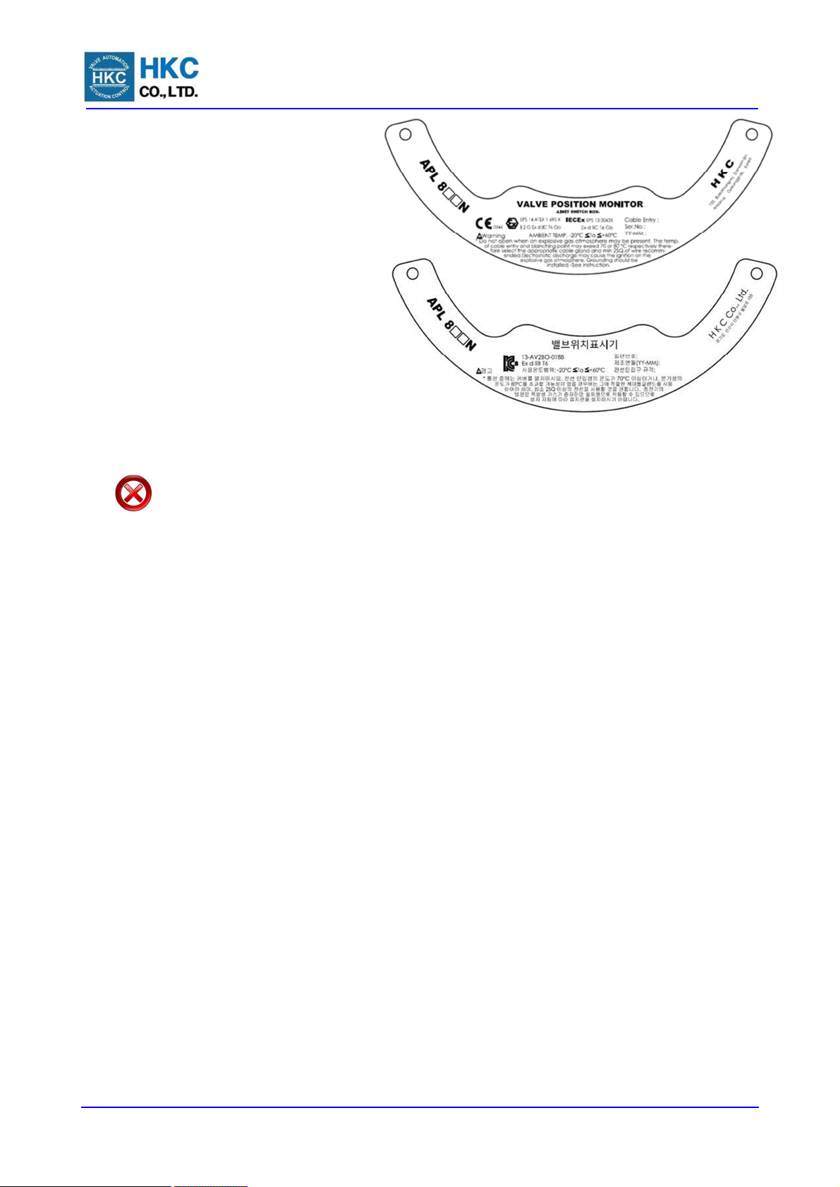
4.1. Marking
HKC Logo / Trade mark
Model
Switches type
Enclosure type & Cert No. for flame proof:
Ambient temperature
Serial No.
Manufacturred year & month (YY-MM)
Cable entry size
Warning letter
Maker address
4.2. Pre-Installation for use in
potentially explosive atmosphere
Installation, commissioning, maintenance, repairs and modification work must only be performed by
qualified personnel with extensive knowledge on how to work explosion-proof electrical equipment.
Warning : Read this installation and maintenance manual carefully and completely Before attempting
to install, operate, or troubleshoot the HKC product.
4.2.1. Cable Connection
① Sealing devices must be used and shall be fitted directly at enclosure wall when using conduit.
② Cable glands shall be suitable for the environment and shall be certified as flameproof it used in
Zone 1 application.
③ Cable glands and shall be installed minimum 6 full threads and the length of thread is minimum
8mm.
④ The temperature at cable entry and blanching point may exceed 70℃ and 80℃ respectively
therefore select the appropriate cable gland and min 2SQ of wire is recommended when you install”
⑤ For cable entries or conduit entries that are not used, user or installer shall close by certified
blanking elements(stopping plugs) so that the flameproof properties of the enclosure are
maintained.
4.2.2. Groundings
① Always ground the enclosure in accordance with local electric codes. The most effective enclosure
grounding method is a direct. Connection to earth ground with minimal impedance. Methods for
grounding the enclosure include:
Internal ground connection : The internal ground is located inside the body.
External ground connection : The ground bracket is located on the side of body.
(Min 2SQ wire required)
4.2.3. Special Condition for safe use
① Electrostatic discharge from window(over 1GΩ) may cause the ignition on the explosive gas
atmosphere. By adapting the conducting window bolts make reduce the risk from electrostatic
discharge.
② Before installation or maintenance products, shut off incoming power and grounding should be
connected.
4.3. Initial inspection
When the user receipts the product, inspect the condition of the product and ensure the name plate
comparing with order sheet.
4.3.1. Remove packing wrap or wooden box carefully. Inspect the product for any physical damage that
may have occurred during shipment.
4.3.2. Check the product specification with product ordered. If a wrong product has been shipped,
immediately inform to our coordinator.
For IECEx and ATEX
 Loading...