

Page 1

•English p.2
•Deutsch S.8
•Français p.14
•Italiano p.20
•Español p.26
•にほんご P.32
Manual 1.0
Page 2
Important Safety Instructions! Read before
connecting!
This product has been built by the manufacturer in accordance
with IEC 60065 and left the factory in safe working order. To
maintain this condition and ensure non-risk operation, the user
must follow the advice and warning comments found in the
operating instructions. If this product shall be used in vehicles,
ships or aircraft or at altitudes exceeding 2000 m above sea
level, take care of the relevant safety regulations which may
exceed the IEC 60065 requirements.
WARNING: To prevent the risk of fire and shock hazard, do not
expose this appliance to moisture or rain. Do not open case – no
user serviceable parts inside. Refer service to qualified service
personnel.
This symbol, wherever it appears, alerts you to the
presence of uninsulated dangerous voltage inside the enclosure –
voltage that may be sufficient to constitute a risk of shock.
This symbol, wherever it appears, alerts you to the
presence of externally accessible hazardous voltage. External
wiring connected to any terminal marked with this symbol must
be a “ready made cable” complying with the manufacturers
recommendations, or must be a wiring installed by instructed
persons only.
This symbol, wherever it appears, alerts you to important
operating and maintenance instructions in the accompanying
literature. Read the manual.
This symbol, wherever it appears, tells you: Take care!
Hot surface! To prevent burns you must not touch.
• Read these instructions.
• Keep these instructions.
• Follow all warnings and instructions marked on the product and
in this manual.
• Do not use this product near water. Do not place the product
near water, baths, wash basins, kitchen sinks, wet areas,
swimming pools or damp rooms.
• Do not place objects containing liquid on the product – vases,
glasses, bottles etc.
• Clean only with dry cloth.
• Do not remove any covers or sections of the housing.
• The set operating voltage of the product must match the local
mains supply voltage. If you are not sure of the type of power
available consult your dealer or local power company.
• To reduce the risk of electrical shock, the grounding of this
product must be maintained. Use only the power supply cord
provided with this product, and maintain the function of the
center (grounding) pin of the mains connection at any time. Do
not defeat the safety purpose of the polarized or groundingtype plug.
• Protect the power cord from being walked on or pinched
particularly at plugs, convenience receptacles, and the point
where they exit from the device! Power supply cords should
always be handled carefully. Periodically check cords for cuts
or sign of stress, especially at the plug and the point where the
cord exits the device.
• Never use a damaged power cord.
• Unplug this product during lightning storms or when unused for
long periods of time.
• This product can be fully disconnected from mains only by
pulling the mains plug at the unit or the wall socket. The
product must be placed in such a way at any time, that
disconnecting from mains is easily possible.
• Fuses: Replace with IEC127 (5x20mm) type and rated fuse for
best performance only! It is prohibited to use “patched fuses”
or to short the fuse-holder. Replacing any kind of fuses must
only be carried out by qualified service personal.
• Refer all servicing to qualified service personnel. Servicing is
required when the unit has been damaged in any way, such as:
- When the power cord or plug is damaged or frayed.
- If liquid has been spilled or objects have fallen into the product.
- If the product has been exposed to rain or moisture.
- If the product does not operate normally when the operating
instructions are followed.
- If the product has been dropped or the cabinet has been
damaged.
• Do not connect external speakers to this product with an
impedance lower than the rated impedance given on the
product or in this manual. Use only cables with sufficient cross
section according to the local safety regulations.
• Keep away from direct sunlight.
• Do not install near heat sources such as radiators, heat
registers, stoves or other devices that produce heat.
• Do not block any ventilation openings. Install in accordance
with manufacturer’s instructions. This product must not be
placed in a built-in installation such as a rack unless proper
ventilation is provided.
• Always allow a cold device to warm up to ambient temperature,
when being moved into a room. Condensation can form inside it
and damage the product, when being used without warming up.
• Do not place naked flame sources, such as lighted candles on
the product.
• The device must be positioned at least 20 cm/8“ away from
walls.
• Use only with the cart, stand, tripod, bracket or table specified
by the manufacturer or sold with the product. When a cart is
used, use caution when moving the cart/product combination to
avoid injury from tip-over.
• Use only accessories recommended by the manufacturer, this
applies for all kind of accessories, for example protective
covers, transport bags, stands, wall or ceiling mounting
equipment. In case of attaching any kind of accessories to the
product, always follow the instructions for use, provided by the
manufacturer. Never use fixing points on the product other than
specified by the manufacturer.
• This appliance is NOT suitable to be used by any person or
persons (including children) with limited physical, sensorical or
mental ability, or by persons with insufficient experience and/
or knowledge to operate such an appliance. Children under
4 years of age must be kept away from this appliance at all
times.
• Never push objects of any kind into this product through
cabinet slots as they may touch dangerous voltage points or
short out parts that could result in risk of fire or electric shock.
• This product is capable of delivering sound pressure levels
in excess of 90 dB, which may cause permanent hearing
damage! Exposure to extremely high noise levels may cause a
permanent hearing loss. Wear hearing protection if continously
exposed to such high levels.
• The manufacturer only guarantees the safety, reliability and
efficiency of this product if:
- Assembly, extension, re-adjustment, modifications or repairs
are carried out by the manufacturer or by persons authorized
to do so.
- The electrical installation of the relevant area complies with the
requirements of IEC (ANSI) specifications.
- The unit is used in accordance with the operating instructions.
- The unit is regularly checked and tested for electrical safety by
a competent technician.
General Notes on Safety for Loudspeaker
Systems
Mounting systems may only be used for those loudspeaker
systems authorized by the manufacturer and only with the
mounting accessories specified by the manufacturer in the
installation instructions. Read and heed the manufacturer’s
installation instructions. The indicated load-bearing capacity
cannot be guaranteed and the manufacturer will not be liable for
damages in the event of improper installation or the use of
unauthorized mounting accessories.
The system’s load-bearing capacity cannot be guaranteed and
the manufacturer will not be liable for damages in the event
that loudspeakers, mounting accessories, and connecting and
attaching components are modified in any way.
Components affecting safety may only be repaired by the
manufacturer or authorized agents, otherwise the operating
permit will be voided.
Installation may be performed qualified personnel only, and
then only at pick-points with sufficient load-carrying capacity and
in compliance with local building regulations. Use only the
mounting hardware specified by the manufacturer in the
installation instructions (screws, anchors, etc.). Take all the
precautions necessary to ensure bolted connections and other
threaded locking devices will not loosen.
Fixed and portable installations (in this case, speakers and
mounting accessories) must be secured by two independent
safeties to prevent them from falling. Safeties must be able to
catch accessories or parts that are loose or may become loose.
Ensure compliance with the given national regulations when
using connecting, attaching, and rigging devices. Factor potential
dynamic forces (jerk) into the equation when determining the
proper size and load-bearing capacity of safeties.
Be sure to observe speaker stands’ maximum load-bearing
capacity. Note that for reasons of design and construction, most
speaker stands are approved to bear centric loads only; that is,
the speakers’ mass has to be precisely centered and balanced.
Ensure speaker stands are set up stably and securely. Take
appropriate added measures to secure speaker stands, for
example when:
- the floor or ground surface does not provide a stable, secure
base.
- they are extended to heights that impede stability.
- high wind pressure may be expected.
- there is the risk that they may be knocked over by people.
Special measures may become necessary as precautions against
unsafe audience behavior. Do not set up speaker stands in
evacuation routes and emergency exits. Ensure corridors are
wide enough and put proper barriers and markings in place
when setting speaker stands up in passageways. Mounting and
dismounting are especially hazardous tasks. Use aids suitable
for this purpose. Observe the given national regulations when
doing so.
Wear proper protection (in particular, a helmet, gloves, and
safety shoes) and use only suitable means of ascent (ladders,
scaffolds, etc.) during installation. Compliance with this
requirement is the sole responsibility of the company performing
the installation.
After installation, inspect the system comprised of the
mounting fixtures and loudspeakers to ensure it is properly
secured.
The operator of loudspeaker systems (fixed or portable) must
regularly inspect or task a third party to regularly inspect all
system components in accordance with the given country’s
regulations and have possible defects repaired immediately.
We also strongly recommend maintaining a logbook or the like to
document all inspections.
When deploying speakers outdoors, be sure to take into account
the stability and load-bearing capacity of platforms and surfaces;
loads and forces exerted by wind, snow, and ice; as well as
thermal influences. Also be sure to provide sufficient safety
margins for the rigging points used for flown systems. Observe
the given national regulations when doing so.
Professional loudspeaker systems can produce harmful
volume levels. Even prolonged exposure to seemingly harmless
levels (starting at about 95 dBA SPL) can cause permanent
hearing damage! Therefore we recommend that everyone who is
exposed to high volume levels produced by loudspeaker systems
wears professional hearing protection (earplugs or earmuffs).
Manufacturer: Stamer Musikanlagen GmbH, Magdeburger Str. 8,
66606 St. Wendel, Germany
Version 2.2 01/2011
Page 3
Lucas Nano 300 1.0
Congratulations and thank you for choosing an HK AUDIO
product!
It’s all in the name: LUCAS NANO 300 takes our successful LUCAS
systems another step up the evolutionary ladder. Comprised of two
satellites and an ultra compact subwoofer, it comes with all the power
electronics on board. Packed with unprecedented audio design
technologies and featuring a newly developed triple-channel Class-D
power amp engineered to save space, LUCAS NANO 300 delivers
stunning sound in a package that leaves a very small footprint. The
high-performance electronic circuitry, carefully fine-tuned to match
the speakers, delivers 230 watts of power output and protects against
overloads. Paired with an intuitive three-channel mixer, this circuitry
makes the system remarkably easy to handle.
There’s no need to fuss with a lot of tweaking and tuning: Simply set
up the components, connect the power and signal cables, adjust the
volume and you’re good to go. LUCAS NANO 300, like all our powered
systems, is an end-to-end sound reinforcement solution encompassing
a subwoofer, satellites, and painstakingly tuned electronics.
To help you achieve the best possible audio results, our engineers
developed new technologies and unique features specifically for this
system. And that’s what makes LUCAS NANO 300 stand out from the
crowd of lesser active cabinets.
We hope you enjoy your LUCAS NANO 300 as much as we
enjoyed developing it!
• にほんご
• Español• English • Deutsch • Français • Italiano
Applications and Advantages
• Anyone can easily carry the entire system.
• Setting up for any application takes just a few moments. You don’t
need any outboard gear to run this system.
• The many applications options are practically begging to be used.
Whatever your gig may be - musician, DJ, entertainer, presenter
– you will enjoy the benefits of easy handling and effective sound
reinforcement.
• Take it with you on small stages for music performances or speeches,
use it for presentations in conference rooms or have fun rehearsing
at home in the den, the living room or the garage. But know this:
Wherever you take your LUCAS NANO 300, it will fill the room with
extraordinary sound and powerful, dynamic and balanced audio
performance.
• The integrated three-channel mixer offers lots of helpful, intuitive
controls that let you make the most of all the application options. It
will serve you well as a PA for small stages, a sound system for parties
and as a keyboard, e-drums or guitar monitor when you’re practicing.
• LUCAS NANO 300 offers several setups for use as a stereo and a
monaural system. And the innovative Link function lets you double up
with two LUCAS NANO 300 systems.
3
Page 4
Lucas Nano 300 1.0
1 General Information
1.1 Unpacking and Inventorying
Remove all the component parts of LUCAS NANO 300 from the carton
and make sure you have received all items.
LUCAS NANO 300 consists of a subwoofer and two satellites.
A protective cover and a mains cable are also included.
1.2 Unfastening Transport Latches
Latches secure the LUCAS NANO 300 satellites to the subwoofer to
protect them during transport. Here’s how to undo them:
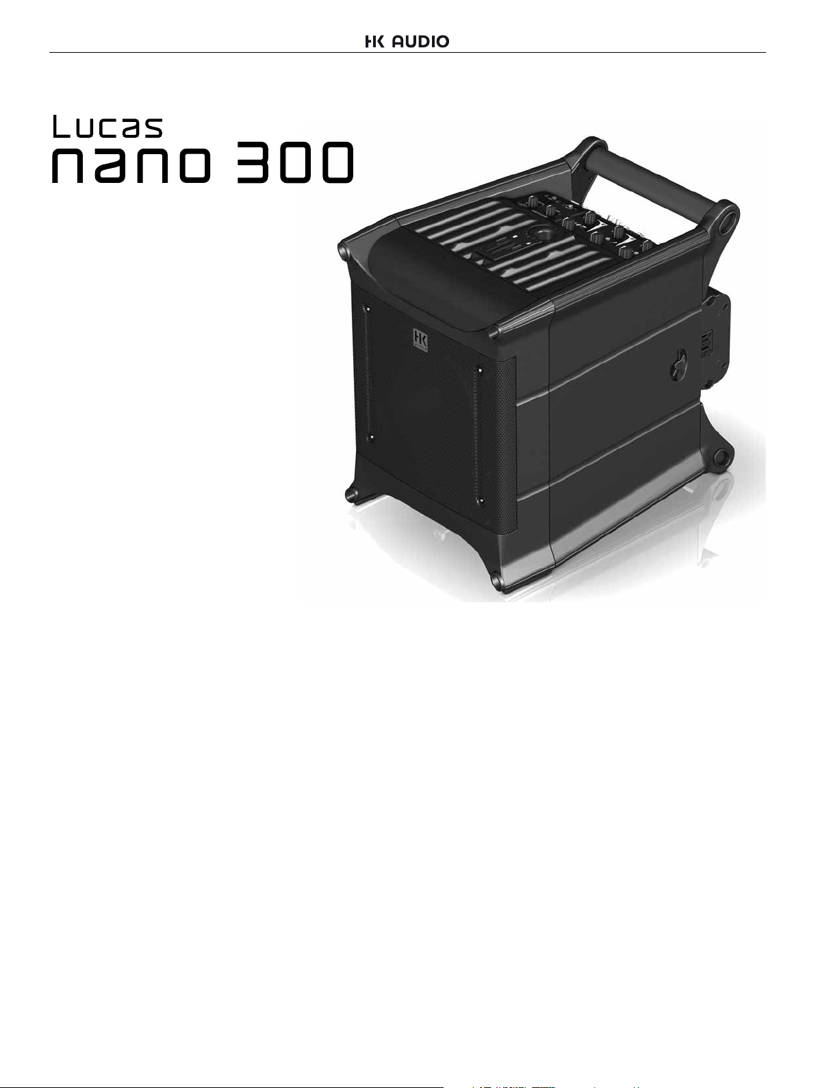
2 Connectors and Controls
Sub
Mode Setup
Mute
AB
A: Rec Out
B: CH 2 Thru
Out
Bal.
Speaker Out
to Satellite
123
1 2 3
Speaker Out
to Satellite
LR
L R
LR L R
Lucas
nano
3OO
2.1 Power/Status Section
12
LR
Balance
Connect a 2nd
LUCAS NANO
Link In/Out
Stereo
• Standing at the back of the system, turn the locking knobs on both
sides backward to unlock the satellites. Remove the two LUCAS
NANO 300 satellites from their cradle.
• Always make sure these knobs engage to lock the speakers down for
transport.
1.3 Easy Click Connector
• This mechanical and electric coupler connects the modules.
Easy Click is very easy to disconnect: Simply push the top satellite back
and lift the enclosure to remove it.
1 Power
This switches LUCAS NANO 300 on and off.
2 Status Indicator
Dual-color LED (green = power on, red =limit/error). The LED briefly
flashes red to tell you the limiter is responding to signal peaks.
Caution! If the Status LED stays red while the system is fully
operational, it is being overloaded. Turn down the signal level! If you
are not feeding a signal into the system and the Status LED stays
red, there has been malfunction.
Note: LUCAS NANO 300 performs a system check after the system is
powered up or the Setup switch is engaged. The Status LED lights up
red for about five seconds during this time. It will light up green if there
is no error and the system is getting mains power.
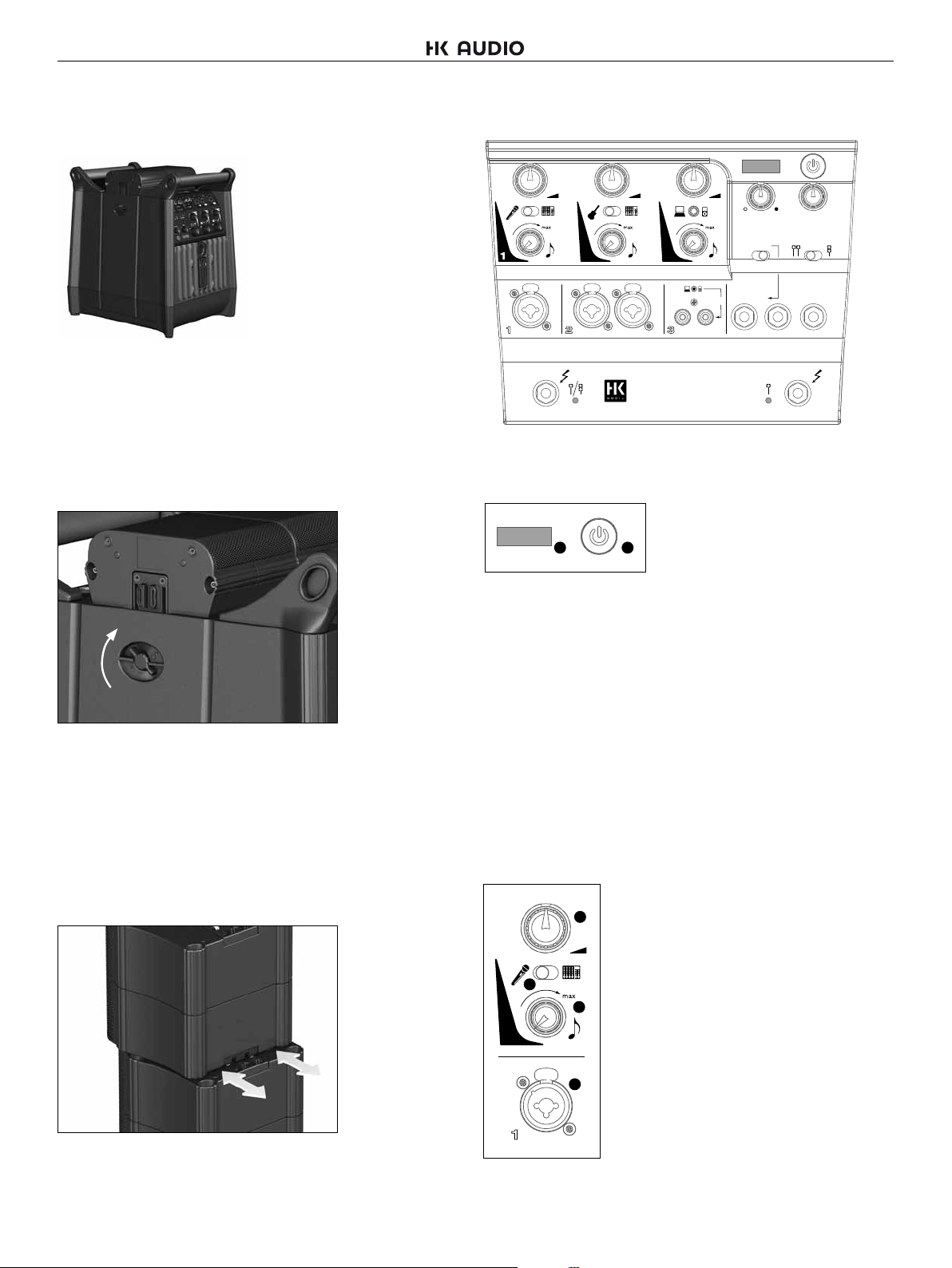
2.2 Input Section 1
3 Volume
This rotary knob adjusts the volume for this input.
3
Twist it counterclockwise to the far left to turn the
signal level all the way down and clockwise to the
far right to turn the level all the way up.
4
1
4 Mic/Line
5
This switch adjusts the input sensitivity or gain
of Input 1 for use with a dynamic microphone
or a line signal. At the same time, it configures
the integrated filter for Voice (microphones) and
Contour (line signal) applications.
6
To connect a satellite, set it on the top panel and push it forward.
4
1
Page 5
Lucas Nano 300 1.0
5 Voice/Contour
This rotary knob tunes the LUCAS NANO 300’s sound to suit the input
signal.
• If the Mic/Line switch is set to „Mic“, this rotary knob adjusts the
sound for speech.
Far left position = no change in tone
Far right position = maximum tuning effect
• When the Mic/Line switch is set to „Line“, you can use this knob to
tune the system for music signals. It boosts low and high frequencies
while cutting midrange frequencies.
Far left position = no change in tone
Far right position = maximum effect
6 Input 1
This multipurpose XLR/1/4" mono input is electrically balanced to
accept a dynamic microphone or a line signal. The input signal is routed
to both the left and right outputs of LUCAS NANO 300.
2.3 Input Section 2
7
8
9
2
2
LR
10 Input 2 L/R
This multipurpose XLR/1/4" mono input is electrically balanced to
accept an instrument or a line signal.
7 Volume
See Input Section 1 for a description.
8 Instrument/Line
This switch configures Input 2’s sensitivity
or gain for an instrument such as a guitar or
for a line signal.
9 Contour
This rotary knob voices the audio signal;
that is, it adjusts the tone.
10
It boosts low and high frequencies while
cutting midrange frequencies.
• Far left position = no change in tone
• Far right position = maximum effect
2.4 Input Section 3
11
12
13
3
14
Mute
3
LR
14 Stereo RCA Input
Use this input to connect audio sources such as DVD and BluRay
players, DJ consoles and computers.
11 Volume
See Input Section 1 for a description.
12 Mini-Jack Input (3.5 mm)
Use this stereo input to connect MP3 players
or the headphones output of a laptop.
Heads up: Plugging a connector into this
input mutes the Stereo RCA Input (14).
13 Contour
This rotary knob adjusts the audio signal’s
tone. When it boosts high and low frequencies,
it also rolls off midrange frequencies.
• Far left position = no change in tone
• Far right position = maximum effect
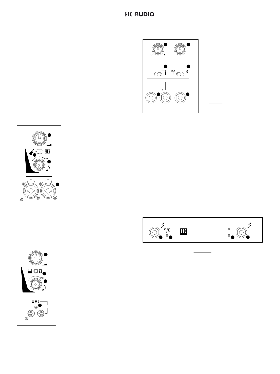
2.5 Output Section
15 16
Sub
Mode Setup
AB
A: Rec Out
B: CH 2 Thru
Out
18 20
Bal.
LR
LR
Balance
17 19
Connect a 2nd
LUCAS NANO
Link In/Out
Stereo
• B: Ch 2 Thru: This mode sends the signal routed into Input 2 (10)
through to this output for monitoring. See the example in the appendix
called Personal Monitoring.
18 Out L/R
This is an electrically balanced 1/4" (6.3 mm) output jack. Depending
on the Mode A/B switch setting, it sends out a composite of all input
signals (including Link In) or just the signal patched into Input 2.
19 Setup
Use this switch to configure LUCAS NANO 300 for mono or stereo
operation.
20 Link In/Out
This 1/4" (6.3 mm) stereo jack serves to connect this LUCAS NANO 300
to another LUCAS NANO 300. Please be sure to use a cord equipped
with stereo 1/4“ (6.3 mm) jack plugs to do this. No other cables will do.
15 Sub
This rotary knob adjusts the
subwoofer’s volume level from -∞ to
+6 dB.
16 Balance
This rotary knob adjusts the relative
levels of the left and right channels.
17 Mode A/B
This switch configures the output
signal sent to Out L/R (19):
• A: Rec Out: This mode sends the
composite signal of channels 1 to 3
and Link In (20) to a connected audio
recorder.
2.6 Speaker Out Section
Speaker Out
to Satellite
Lucas
21 22 22 21
L R
21 Speaker Out to Satellite L / R
nano
3OO
Use these 1/4" (6.3 mm) jacks exclusively to connect LUCAS NANO 300
satellites. Do not connect any other devices. If you do, that device and
LUCAS NANO 300 may be irreparably damaged.
22 Speaker Status Indicators
This dual-color LED tells you what’s going on with the Speaker Outs of
LUCAS NANO 300 (green = speaker output is active, red = inactive).
Enable and disable outputs using the Setup switch in the output section.
Note: LUCAS NANO 300’s outputs are muted during a system check
(see Status LED). The Speaker Status LEDs light up red during this
time (about five seconds).
Speaker Out
to Satellite
2.7 Connector Panel
Mains Socket
Use the factory-included mains cord to connect this socket to a wall
outlet.
Caution! Make sure the local mains voltage matches the voltage
specified on LUCAS NANO 300. Connecting it to the wrong mains
voltage may destroy its electronic components.
• にほんご
• Español• English • Deutsch • Français • Italiano
5
Page 6
Lucas Nano 300 1.0
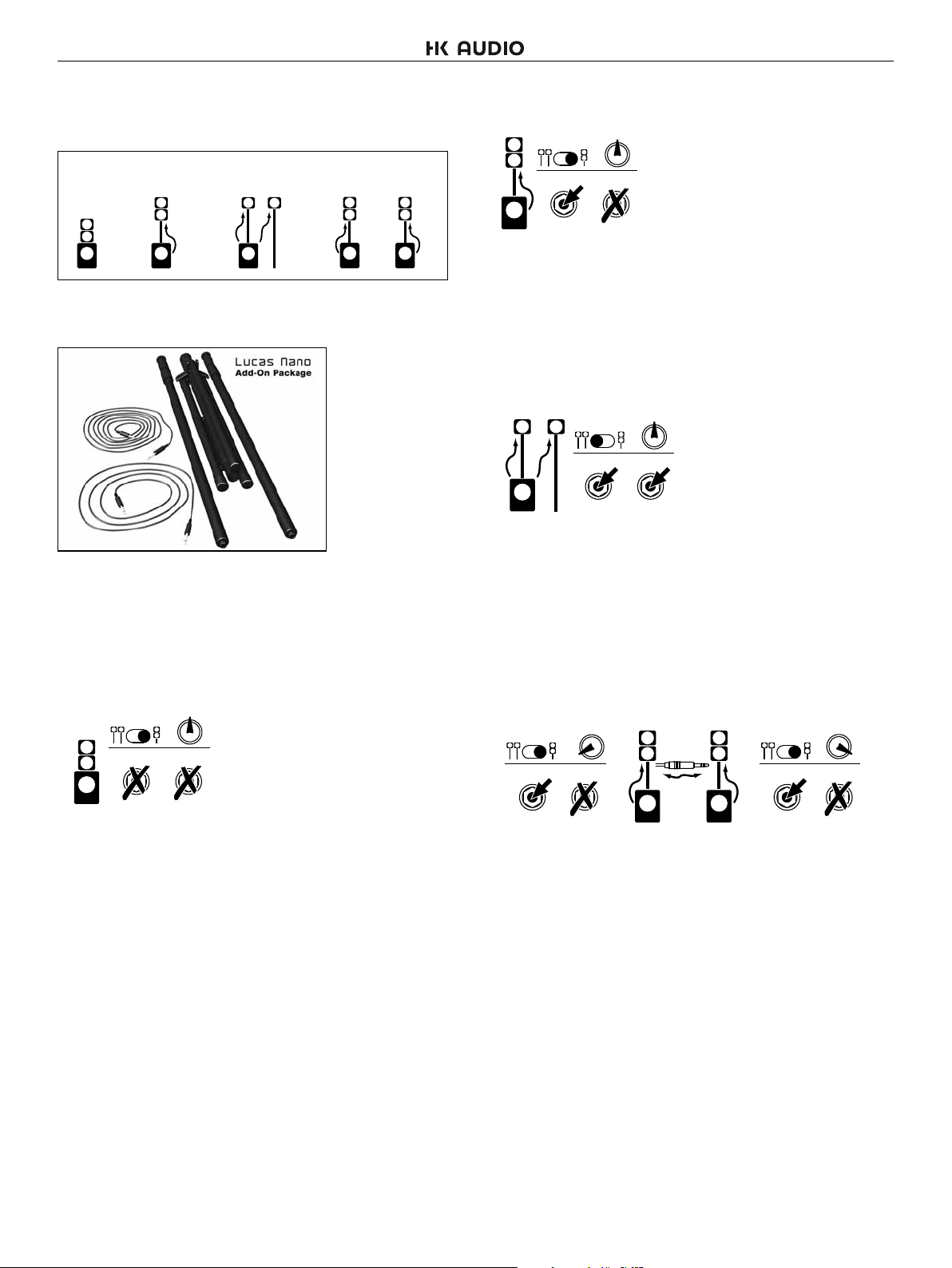
3 Setups
You can set up LUCAS NANO 300 in various configurations:
Mono
System 1
Note that the optionally available LUCAS NANO ADD-ON PACKAGE
affords you the greatest flexibility.
Contents: 1x 8m Link/Speaker cord, 1x 2m Link/Speaker cord, 2x height adjustable pole mount,
1x tripod leg, 4x cable ties, 1x bag
The following examples should help you find the best setup
for your application:
Mono
System 2
Stereo
System
Double Stereo System
LR
(two Mono Systems)
LR
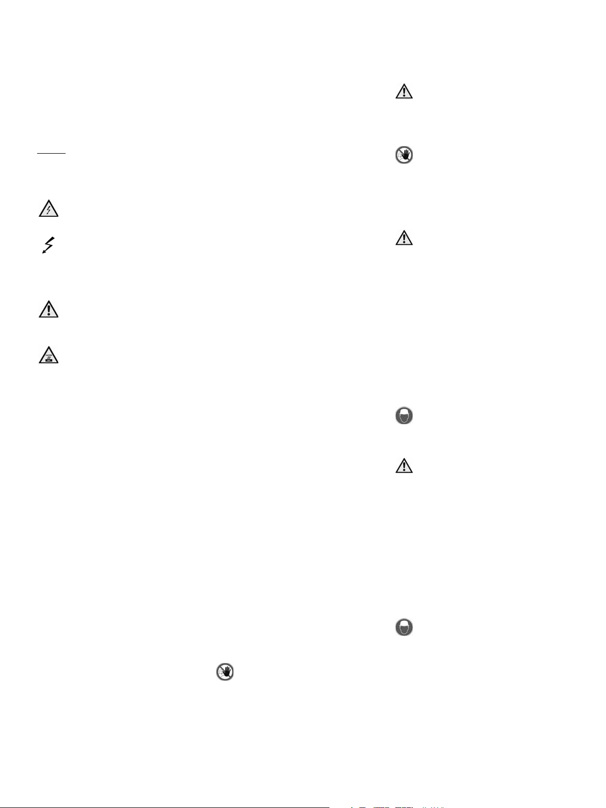
3.2 Mono System 2
Balance
Setup
Speaker Out
LR
RL
Stack and connect the LUCAS NANO 300 satellites as described in
section, „1.3 Easy-Click connector“. Insert the adjustable speaker
pole (optional*) into the pole mount on the subwoofer and attach the
two satellites to it. Use a cord equipped with 1/4" (6.3 mm) jack plugs
(optional*) to connect the LUCAS NANO 300 subwoofer’s Speaker Out
L to the LUCAS NANO 300 satellites. Be sure to set the Setup switch to
Mono (to the right).
3.3 Stereo System
Balance
Setup
Speaker Out
LR
Insert the adjustable speaker pole (optional*) into the pole mount on
the subwoofer and attach one LUCAS NANO 300 satellite to it. Attach
the second satellite to a tripod speaker pole (optional*). Use a cord
equipped with 1/4" (6.3 mm) jack plugs (optional*) to connect the
LUCAS NANO 300 subwoofer’s Speaker Out L to the left LUCAS NANO
300 satellite. Then connect the Speaker Out to Satellite R port to the
right LUCAS NANO 300 satellite. Be sure to set the Setup switch to
Stereo (to the left).
RL
3.1 Mono System 1
Balance
Setup
Speaker Out
LR
Stack and connect the LUCAS NANO 300 satellites as described in
section „1.3, Easy Click Connector“. Then connect the two LUCAS
NANO 300 satellites to the LUCAS NANO 300 subwoofer. Be sure to set
the Setup switch to Mono (to the right).
RL
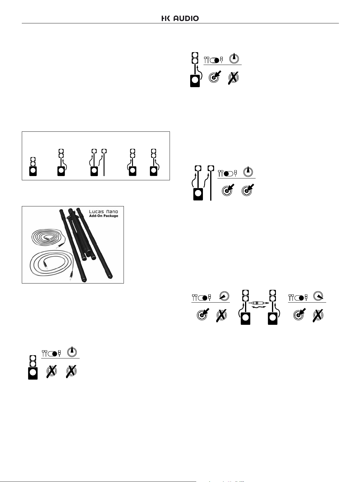
3.4 Double Stereo System
(two LUCAS NANO 300 systems)
Setup
LR
Speaker Out
LR
Link
LR
Use
Stereo
Cable!
Stack and connect two each LUCAS NANO 300 satellites as described
in section „1.3 Easy-Click connector“. Then insert an adjustable
speaker pole (optional*) into each subwoofer pole mount and attach
two satellites to each pole. Use cords equipped with 1/4" (6.3 mm) jack
plugs (optional*) to connect the LUCAS NANO 300 subwoofers’ Speaker
Out L ports to the LUCAS NANO 300 satellites. Be sure to set the Setup
switch on both systems to Mono (to the right).
Use a cord equipped with stereo 1/4" (6.3 mm) jack plugs to connect
the two LUCAS NANO 300 subwoofers’ Link In/Out ports and create a
stereo system. Be sure to adjust each side’s Balance knob accordingly;
that is, turn one to the left and the other to the right.
You’ll find examples of more applications for two combined LUCAS
NANO 300 systems, for example, to cover two rooms, in the appendix
starting on page 38.
*Included in the LUCAS NANO ADD-ON PACKAGE
Setup
LR
Speaker Out
LR
6
Page 7

Lucas Nano 300 1.0
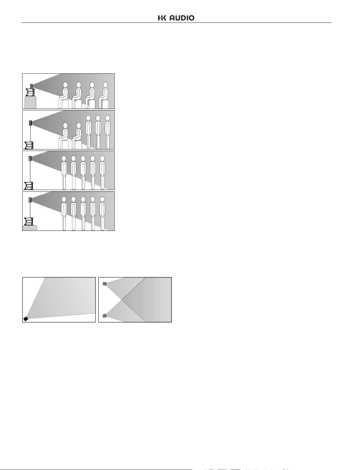
4 Aiming Satellites
4.1 Vertical Alignment
To treat your audience to the most balanced audio image, always aim
LUCAS NANO 300 satellites to ear level.
6 Technical Specifi cations
Subwoofer
Power output 160 W @ 2 ohms
Frequency response 44 Hz – fx
Max. SPL@10%THD* 116 dB
Max. SPL Peak* 118 dB
Dimensions (WxHxD) 30 x 39 x 42 cm /
11-13/16 x 15-11/32 x 16-17/32"
Weight 8.3 kg / 18.3 lbs.
*half space
Satellite Single Double
Power output 35 W @ 8 ohms 70 W @ 4 ohms
Frequency response 190 Hz – 20 kHz 190 Hz – 20 kHz
Max. SPL@10%THD* 112 dB 116 dB
Max. SPL Peak* 116 dB 120 dB
Dimensions 13 x 13 x 11.5 cm 13 x 24 x 11.5 cm
(WxHxD) 5-1/8 x 5-1/8 x 4-17/32“ 5-1/8 x 9-15/16 x 4-17/32“
Weight 1 kg / 2.2 lbs. 2 kg / 4.4 lbs.
*half space
General Technical Specifications
Max. current consumption 3 A at 90 VAC
Inrush current 48 A
Multi-voltage power supply 90 V – 240 V
• にほんご
4.2 Horizontal Alignment
The satellites’ horizontal dispersion angle is around 60°. Depending on
room size and whether it’s a mono or stereo setup, you may want to turn
the satellites in towards the audience area.
Stereo
Mono
5 Example Applications
You’ll find more examples of applications, configurations and setups in
the appendix starting on page 38, including setups for:
• Presentations
• Entertainers
• Instrument/ vocals with live recording
• Keyboard monitoring on stage
• E-drum monitoring at home
• Personal monitoring for e-drums
• DJs
• Español• English • Deutsch • Français • Italiano
• Setup, cabling and alignment when using two LUCAS NANO 300
systems
7
Page 8
Wichtige Sicherheitshinweise! Bitte vor
Anschluss lesen!
Dieses Produkt wurde gemäß IEC 60065 hergestellt und hat
das Werk in einem sicheren, betriebsfähigen Zustand verlassen.
Um diesen Zustand zu erhalten und um einen gefahrlosen
Betrieb zu gewährleisten, ist es notwendig, dass der Benutzer
die Empfehlungen und Warnhinweise befolgt, die in der
Betriebsanleitung zu finden sind. Bei Einsatz dieses Produktes
in Fahrzeugen, Schiffen oder Flugzeugen, oder in Höhen
oberhalb 2000 m Meereshöhe müssen die entsprechenden
Sicherheitsstandards zusätzlich zur IEC 60065 beachtet werden.
WARNUNG: Um das Risiko von Feuer oder Stromschlag zu
verhüten, darf dieses Gerät nicht Feuchtigkeit oder Regen
ausgesetzt werden. Öffnen Sie das Gehäuse nicht – im Inneren
gibt es keine Bauteile, die vom Benutzer wartbar sind. Die
Wartung darf nur von einem qualifiziertem Kundendienst
durchgeführt werden.
Dieses Symbol, wo immer es erscheint, warnt Sie vor
gefährlicher, nicht isolierter Spannung im Gehäuse – Spannung,
die möglicherweise genügt, eine Stromschlaggefahr darzustellen.
Dieses Symbol, wo immer es erscheint, warnt Sie vor
außen zugänglicher, gefährlicher Spannung. Eine Verbindung zu
jeder Anschlussklemme, die mit diesem Symbol versehen ist, darf
nur mit konfektioniertem Kabel hergestellt werden, dass den
Empfehlungen des Herstellers genügt, oder mit Kabel, das von
qualifiziertem Personal installiert wurde.
Dieses Symbol, wo immer es erscheint, macht Sie auf
wichtige Bedienungs- und Wartungsanweisungen aufmerksam,
die in beiliegenden Unterlagen zu finden sind. Bitte lesen Sie das
Handbuch.
Dieses Symbol, wo immer es erscheint, sagt Ihnen:
Vorsicht! Heiße Oberfläche! Um Verbrennungen zu vermeiden,
nicht anfassen.
• Bitte lesen Sie diese Anweisungen.
• Bewahren Sie diese Anweisungen auf.
• Befolgen Sie alle Warnhinweise und Anweisungen auf dem
Gerät und in dieser Anleitung.
• Benutzen Sie dieses Gerät nicht in der Nähe von Wasser. Stellen
Sie das Gerät nicht in der Nähe von Wasser, Badewannen,
Waschbecken, Küchenspülen, nassen Stellen, Schwimmbecken
oder feuchten Räumen auf.
• Stellen Sie keine Gefäße, wie Vasen, Gläser, Flaschen usw., die
Flüssigkeiten enthalten, auf das Gerät.
• Reinigen Sie das Gerät nur mit einem trockenen Tuch.
• Entfernen Sie keine Abdeckungen oder Teile des Gehäuses.
• Die auf dem Gerät eingestellte Betriebsspannung muss mit der
örtlichen Spannung der Netzstromversorgung übereinstimmen.
Wenn Sie sich nicht sicher sind, welche Spannung in Ihrem
Netz zur Verfügung steht, konsultieren Sie bitte Ihren Händler
oder den örtlichen Stromversorger.
• Um das Risiko eines Stromschlags zu verringern, muss die
Erdung des Gerätes beibehalten werden. Verwenden Sie nur das
mitgelieferte Stromführungskabel und behalten Sie die Funktion
der seitlichen, geerdeten Schutzkontakte des Netzanschlusses
immer aufrecht. Versuchen Sie nicht, die Sicherheitsaufgabe
des geerdeten Steckers zu umgehen.
• Schützen Sie das Stromführungskabel vor Betreten
und Quetschen, besonders in der Nähe der Stecker,
Gerätesteckdosen – und dort, wo sie am Gerät austreten!
Stromführungskabel sollten immer vorsichtig behandelt werden.
Kontrollieren Sie die Stromführungskabel in regelmäßigen
Abständen auf Einschnitte und Anzeichen von Abnutzung,
besonders in der Nähe des Steckers und an der Verbindung
zum Gerät.
• Benutzen Sie niemals ein beschädigtes Stromführungskabel.
• Ziehen Sie bei Gewittern den Stecker des Gerätes und wenn
das Gerät über einen längeren Zeitraum nicht benutzt wird.
• Dieses Gerät wird nur vollständig von Stromnetz getrennt, wenn
der Stecker vom Gerät oder aus der Steckdose gezogen wird.
Das Gerät sollte so aufgestellt werden, dass das Trennen vom
Stromnetz leicht möglich ist.
• Sicherungen: Ersetzen Sie Sicherungen nur mit dem Typ IEC127
(5x20mm) und dem korrekten Nennwert, um die optimale
Leistung zu gewährleisten! Es ist untersagt, kurzgeschlossene
Sicherungen zu verwenden oder den Sicherungshalter zu
überbrücken. Sicherungen dürfen nur von qualifiziertem
Personal gewechselt werden.
• Alle Wartungsarbeiten sollten nur von qualifiziertem Personal
ausgeführt werden. Wartung ist notwendig, wenn das Gerät auf
irgendeine Weise beschädigt wurde, wie zum Beispiel:
- Wenn das Stromführungskabel oder der Stecker beschädigt
oder abgenutzt ist.
- Wenn Flüssigkeit oder Gegenstände in das Gerät gelangt sind.
- Wenn das Gerät Regen oder Feuchtigkeit ausgesetzt war.
- Wenn das Gerät nicht ordnungsgemäß funktioniert, obwohl die
Bedienungsanleitung beachtet wurde.
- Wenn das Gerät hingefallen ist oder das Gehäuse beschädigt
wurde.
• Beim Anschluss von Lautsprechern an dieses Gerät darf
die auf dem Gerät oder in dieser Anleitung angegebene
Mindestimpedanz nicht unterschritten werden. Die verwendeten
Kabel müssen entsprechend den lokalen Regelungen über einen
ausreichenden Querschnitt verfügen.
• Halten Sie das Gerät vom Sonnenlicht fern.
• Installieren Sie das Gerät nicht in der Nähe von Wärmequellen,
wie zum Beispiel Heizkörper, Heizregister, Öfen oder anderen
Geräten, die Hitze erzeugen.
• Verstopfen Sie nicht die Lüftungsöffnungen. Installieren Sie
das Gerät entsprechend der Anleitung des Herstellers. Das
Gerät darf nicht eingebaut werden – wie zum Beispiel in einen
Gestellrahmen, es sei denn, dass für angemessene Belüftung
gesorgt wird.
• Ein kaltes Gerät sollte immer auf die Umgebungstemperatur
erwärmt werden, wenn es in einen Raum transportiert wird.
Es könnte sich Kondensation im Inneren bilden, die das Gerät
beschädigt, wenn es ohne vorherige Erwärmung benutzt wird.
• Stellen Sie keine offenen Flammen, wie brennende Kerzen, auf
das Gerät.
• Das Gerät sollte mindestens 20 cm von Wänden aufgestellt
werden.
• Das Gerät darf nur mit Rollwagen, Ständern, Stativen,
Tischen oder Halterungen benutzt werden, die vom Hersteller
spezifiziert sind oder zusammen mit dem Gerät verkauft
wurden. Wenn ein Rollwagen benutzt wird, seien Sie vorsichtig,
wenn Sie die Rollwagen/Geräte-Kombination transportieren, um
Verletzungen durch Umkippen zu vermeiden.
• Verwenden Sie nur Zubehör, das vom Hersteller empfohlen
ist. Das gilt für alle Arten von Zubehör, wie zum Beispiel
Schutzabdeckungen, Transporttaschen, Ständer sowie Wandund Deckenhalterungen. Wenn Sie irgendein Zubehör am Gerät
anbringen, befolgen Sie immer die Anleitungen des Herstellers.
Benutzen Sie nur die Befestigungspunkte des Geräts, die vom
Hersteller vorgesehen sind.
• Dieses Gerät ist NICHT geeignet für eine Person oder Personen
(einschließlich Kindern) mit eingeschränkten physischen,
sensorischen und geistigen Fähigkeiten, oder für Personen mit
unzulänglicher Erfahrung und/oder Fachkenntnis, um solch
ein Gerät zu bedienen. Kinder unter 4 Jahren sollten stets von
diesem Gerät fern gehalten werden.
• Es sollten keinerlei Gegenstände durch die Gehäuseschlitze
eingeführt werden, da dadurch gefährliche, spannungsführende
Bauteile berührt oder kurzgeschlossen werden können. Dies
könnte zu einer Feuer- oder Stromschlaggefahr führen.
• Dieses Gerät ist imstande, Schalldruckpegel von mehr als
90 dB zu produzieren. Dies könnte zu einem dauerhaften
Hörschaden führen! Eine Belastung durch extrem hohe
Geräuschpegel kann zu einem dauerhaften Gehörverlust führen.
Bei einer anhaltenden Belastung durch solch hohe Pegel sollte
ein Gehörschutz getragen werden.
• Der Hersteller gewährleistet die Sicherheit, Zuverlässigkeit und
Leistung des Gerätes nur unter folgenden Voraussetzungen:
- Einbau, Erweiterung, Neueinstellung, Modifikationen oder
Reparaturen werden vom Hersteller oder autorisiertem Personal
ausgeführt.
- Die elektrische Installation des betreffenden Bereiches
entspricht den Anforderungen der IEC (ANSI) Maßgaben.
- Das Gerät wird entsprechend der Bedienungsanleitung benutzt.
- Das Gerät wird regelmäßig von einem fachkundigen Techniker
auf elektrische Sicherheit geprüft und getestet.
Allgemeine Sicherheitshinweise für
Lautsprechersysteme
Befestigungssysteme dürfen ausschließlich für die vom
Hersteller freigegebenen Lautsprechersysteme und mit dem in
der Montageanleitung genannten Montage-Zubehör verwendet
werden. Die Montagehinweise des Herstellers sind dabei
unbedingt zu beachten. Bei unsachgemäßer Montage bzw.
Verwendung von nicht freigegebenem Montage-Zubehör kann die
angegebene Belastung nicht garantiert und keinerlei Haftung
seitens des Herstellers übernommen werden.
Sollten Änderungen an Lautsprechern, an Montage-Zubehör,
Verbindungs- und Befestigungselementen sowie Anschlagmitteln
vorgenommen werden, kann die Tragfähigkeit des Systems nicht
mehr garantiert werden und seitens des Hersteller keinerlei
Haftung übernommen werden.
Reparaturen an sicherheitsrelevanten Bauteilen dürfen nur
vom Hersteller oder Bevollmächtigten durchgeführt werden,
andernfalls erlischt die Betriebserlaubnis.
Die Installation darf ausschließlich durch Sachkundige und
nur an Montagepunkten mit ausreichender Tragfähigkeit, ggf.
unter der Berücksichtigung von Bauauflagen, erfolgen. Das vom
Hersteller in der Montageanleitung vorgeschriebene
Befestigungsmaterial (Schrauben, Dübel, etc.) muss verwendet
werden. Schraubverbindungen müssen durch geeignete
Maßnahmen gegen Lösen gesichert sein.
Ortsfeste oder mobile Installationen (hier Lautsprecher inkl.
Montagezubehör) müssen durch zwei unabhängig voneinander
wirkende Einrichtungen gegen Herabfallen gesichert sein. Lose
Zusatzteile oder sich lösende Teile müssen durch geeignete
Einrichtungen aufgefangen werden können. Bei Verwendung von
Verbindungs- und Befestigungselementen sowie Anschlagmitteln
sind die nationalen Vorschriften zu beachten. Hinsichtlich der
Bemessung der Sicherungsmittel sind mögliche dynamische
Belastungen (Ruckkräfte) mit zu berücksichtigen.
Bei Stativen ist vor allem die maximale Traglast zu
beachten. Außerdem sind die meisten Stative aus konstruktiven
Gründen nur für das Tragen von genau zentrischer Belastung
zugelassen. Stative müssen standsicher aufgestellt werden.
Stative sind durch geeignete Maßnahmen zusätzlich zu sichern,
wenn zum Beispiel:
- ihre Aufstandfläche keinen sicheren Stand zulässt,
- ihre Höhen die Standsicherheit einschränken,
- mit zu hohem Winddruck zu rechnen ist,
- damit zu rechnen ist, dass sie durch Personen umgestoßen
werden.
Besondere Maßnahmen können auch zur Vorsorge gegen
gefährdendes Verhalten von Zuschauern erforderlich werden.
Stative dürfen nicht in Flucht- und Rettungswegen aufgestellt
werden. Bei Aufstellung in Verkehrswegen ist auf die erforderliche
Breite der Wege und auf ordnungsgemäße Absperrung sowie
Kennzeichnung zu achten. Beim Auf- und Absetzen ist eine
besondere Gefährdung gegeben. Hierzu sind geeignete Hilfsmittel
zu verwenden. Es sind hierbei die nationalen Vorschriften zu
beachten.
Während der Montage ist geeignete Schutzausrüstung
(insbesondere Kopfschutz, Handschuhe und Sicherheitsschuhe) zu
tragen und es sind nur geeignete Aufstiegshilfen (Leitern,
Gerüste, etc.) zu verwenden. Die Verantwortung dafür liegt alleine
beim ausführenden Installationsbetrieb.
Nach der Montage ist die Aufhängung des System aus
Halterung und Lautsprecher auf sichere Befestigung zu
überprüfen.
Der Betreiber von Lautsprechersystemen (ortsfest oder mobil) ist
verpflichtet, alle Systemkomponenten unter Berücksichtigung der
jeweils nationalen Regelungen regelmäßig zu überprüfen bzw.
prüfen zu lassen und mögliche Schäden unverzüglich beseitigen
zu lassen.
Weiterhin raten wir dringend zu einer ausführlichen
Dokumentation aller Überprüfungsmaßnahmen
in Prüfbüchern o.ä.
Beim Einsatz von Lautsprechern im Freien sind für
Standsicherheit und Tragfähigkeit von Aufbauten und Flächen
insbesondere auch die Windlasten, Schnee- und Eislasten
sowie thermische Einflüsse zu berücksichtigen. Insbesondere
die Lastaufnahmepunkte geflogener Systeme sollten hier mit
ausreichenden Sicherheitsreserven dimensioniert werden. Es sind
hierbei die nationalen Vorschriften zu beachten.
Professionelle Lautsprechersysteme sind in der Lage,
gesundheitsschädliche Schallpegel zu erzeugen. Selbst die
Einwirkung scheinbar harmloser Schallpegel über einen längeren
Zeitraum kann zu bleibenden Schäden am Gehör führen (ab ca.
95 dBA SPL)! Daher raten wir für alle Personen, die durch den
Betrieb von Lautsprechersystemen dem Einfluss hoher
Schallpegel ausgesetzt sind, zum Tragen von professionellem
Gehörschutz (Ohrstöpsel oder Kapselgehörschutz).
Hersteller: Stamer Musikanlagen GmbH, Magdeburger Str. 8,
66606 St. Wendel, Deutschland
Version 2.2 01/2011
Page 9

Lucas Nano 300 1.0
Vielen Dank, dass Sie sich für ein HK AUDIO Produkt
entschieden haben!
Der Name verpflichtet: LUCAS NANO 300 ist die konsequente Weiterentwicklung unserer erfolgreichen LUCAS Systeme – bestehend aus zwei
Satelliten und einem ultrakompakten Subwoofer, in dem die komplette
Endstufenelektronik integriert ist. Beim LUCAS NANO 300 sorgen neue
Technologien im Akustikdesign und eine neuentwickelte 3-Kanal Class-D
Endstufe in Mikroarchitektur für fantastischen Klang bei gleichzeitig sehr
kompakten Gehäusevolumen. Die Hochleistungselektronik liefert eine
Gesamtleistung von 230 Watt und ist akribisch auf die verwendeten
Lautsprecher abgestimmt. Gleichzeitig gewährleistet sie Schutz vor
Überlastungen und sorgt mit Hilfe des intuitiv bedienbaren 3-KanalMischpults für die schnelle und effektive Bedienung des Systems.
Sie müssen sich um keine komplizierten Einstell- und Einpegelarbeiten
kümmern, sondern brauchen nur die Systemkomponenten aufzustellen,
Netzversorgung und Signalkabel anzuschließen, Pegel justieren
und schon kann es losgehen. LUCAS NANO 300 ist eine komplette
Beschallungslösung wie jedes unserer Aktivsysteme – bestehend aus
Subwoofer, Satelliten und einer akribisch angepassten Elektronik.
Um bestmögliche Ergebnisse zu erzielen, haben unsere Ingenieure
speziell für dieses System neue Technologien und einzigartige Features
entwickelt, die den LUCAS NANO 300 aus der Masse einfacher
Aktivboxen herausheben.
Viel Spaß und Erfolg mit Ihrem LUCAS NANO 300!
• にほんご
• Español• English • Deutsch • Français • Italiano
Anwendungen und Vorteile
• Das komplette System ist besonders leicht und von jeder Person
transportierbar.
• Der Aufbau ist in jeder Anwendung in wenigen Momenten erledigt.
Externe Komponenten für den Betrieb sind nicht notwendig.
• Nutzen Sie die vielseitigen Anwendungsmöglichkeiten – als Musiker,
DJ, Entertainer oder Präsentator. Genießen Sie die Vorteile der
einfachen Handhabung und effektiven Beschallung.
• Ob auf der kleinen Bühne bei Musikdarbietungen oder bei Ansprachen
– ob im Präsentationsraum oder zuhause im Hobbykeller, im Wohnzimmer oder Übungsraum: LUCAS NANO 300 flutet den gesamten
Raum mit einer außergewöhnlichen Sound-Performance – kraftvoll,
dynamisch und gleichmäßig.
• Das integrierte 3-Kanal-Mischpult bietet Ihnen eine Vielzahl von
hilfreichen und intuitiv bedienbaren Features – optimiert für die
Mehrfachnutzung als Beschallungslösung kleiner Bühnen, als
Partysystem, beim Üben als Keyboard-Monitor, an den E-Drums oder
als Gitarrist.
• LUCAS NANO 300 bietet mehrere Setups zur Nutzung als
Stereosystem, Monosystem oder mit Hilfe der innovativen LinkFunktion auch als Double-Setup mit zwei LUCAS NANO 300
Systemen.
9
Page 10

Lucas Nano 300 1.0
1 Allgemeines
1.1 Lieferumfang
Packen Sie den LUCAS NANO 300 Karton aus und überprüfen Sie den
Lieferumfang auf Vollständigkeit.
LUCAS NANO 300 besteht aus einem System-Subwoofer und zwei
Topteilen, im Lieferumfang sind außerdem eine Schutzhülle und ein
Netzkabel enthalten.
1.2 Lösen der Transportsicherung
Die Topteile des LUCAS NANO 300 sind während des Transports im
System-Subwoofer gesichert. Zum Lösen der Transportsicherung gehen
sie folgendermaßen vor:
2 Anschlüsse und Steuerungen
LR
Sub
Balance
Mode Setup
Mute
AB
A: Rec Out
B: CH 2 Thru
Out
Bal.
Connect a 2nd
LUCAS NANO
Link In/Out
Speaker Out
to Satellite
Stereo
123
1 2 3
Speaker Out
to Satellite
LR
L R
LR L R
Lucas
nano
3OO
2.1 Power/Status-Section
12
• Wenn Sie sich hinter dem System befinden, drehen Sie die
Arretierknöpfe an beiden Seiten nach hinten, um die Sicherung
der Topteile zu lösen. Entnehmen Sie die beiden Topteile aus der
Transporthalterung.
• Achten Sie darauf dass die Schraubknöpfe beim Transport immer
verriegelt sind.
1.3 Easy-Click-Verbindung
• mechanische und elektrische Verbindung zwischen den Modulen
Zum Lösen der Easy-Click-Verbindung schieben Sie das obere Topteil
nach hinten. Entnehmen Sie es danach senkrecht nach oben.
1 Power
Schalter zum Einschalten des LUCAS NANO 300.
2 Statusanzeige
Zweifarbige LED (Grün = Power On, Rot =Limit/Fehler). Ein kurzzeitiges
rotes Aufleuchten der LED zeigt das Arbeiten des Limiters bei
Pegelspitzen an.
Achtung! Leuchtet die Status-LED während dem Betrieb dauerhaft
rot, wird das System überlastet. Reduzieren Sie den Signalpegel!
Wenn kein Programmsignal anliegt und die Status-LED dauerhaft rot
leuchtet, liegt ein Fehler vor.
Hinweis: Nach dem Einschalten bzw. nach dem Betätigen des SetupSchalters führt LUCAS NANO 300 einen Systemcheck durch, während
diesem leuchtet die Status-LED für ca. 5 Sekunden rot – sie wird grün
wenn kein Fehler vorliegt, und Netzspannung anliegt.
2.2 Input Section 1
3 Lautstärke
3
Drehregler zur Einstellung der Signallautstärke
für diesen Eingangskanal. In der Stellung
„Linksanschlag“ ist das Signal komplett abgedreht, in der Stellung „Rechtsanschlag“ ist die
4
1
1
maximale Signallautstärke erreicht.
5
4 Mic/Line
Schalter zur Anpassung der Eingangsempfindlichkeit des Input 1 für die Verwendung mit
einem dynamischen Mikrofon oder einem
Line-Signal. Gleichzeitig wird mit diesem
6
Schalter der integrierte Filter zwischen Voice
(Mikrofonanwendung) und Contour (Line-SignalAnwendung) umgeschaltet.
Zum Verbinden der Topteile gehen Sie in umgekehrter Reihenfolge vor.
10
Page 11

Lucas Nano 300 1.0
5 Voice/Contour
Drehregler zur Optimierung der Klangeigenschaften des LUCAS NANO
300 in Abhängigkeit vom Eingangssignal.
• Steht der Mic/Line-Schalter auf „Mic“ erfolgt mit Hilfe des Drehreglers
eine Klangoptimierung für Sprachanwendungen.
Linksanschlag = keine Klangbeeinflussung
Rechtsanschlag = maximale Klangbeeinflussung
• Steht der Mic/Line-Schalter auf „Line“ kann mit dem Drehregler das
Eingangssignal für Musiksignale optimiert werden. Neben Anhebung
des Tief- und Hochtons erfolgt gleichzeitig auch eine Absenkung der
Mitten.
Linksanschlag = keine Klangbeeinflussung
Rechtsanschlag = maximale Klangbeeinflussung
6 Input 1
Elektronisch symmetrierte Kombi-Eingangsbuchse (Mono-XLR/Klinke)
zum Anschluss eines dynamischen Mikrofons oder eines Line-Signals.
Das Eingangssignal liegt sowohl am linken als auch am rechten Ausgang
des LUCAS NANO 300 an.
2.3 Input Section 2
7
8
9
2
2
LR
• Linksanschlag = keine Klangbeeinflussung
• Rechtsanschlag = maximale Klangbeeinflussung
10 Input 2 L/R
Elektronisch symmetrierte Kombi-Eingangsbuchse (XLR/Klinke) zum
Anschluss eines Instruments oder eines Line-Signals.
7 Lautstärke
Beschreibung siehe Input Section 1.
8 Instrument/Line
Schalter zur Einstellung der Eingangsempfindlichkeit des Input 2 für die Verwendung
mit einem Instrument (z.b. Gitarre) oder
einem Line-Signal.
9 Contour
Drehregler zur Klangeinstellung des
10
Audiosignals.
Neben Anhebung des Tief- und Hochtons
erfolgt gleichzeitig auch eine Absenkung
der Mitten.
• Linksanschlag = keine Klangbeeinflussung
• Rechtsanschlag = maximale Klangbeeinflussung.
14 Cinch-Stereo-Input
Eingang zum Anschluss von Audioquellen wie DVD/BluRay-Player, DJMischpult, Computern.
2.5 Output Section
15 16
Sub
Mode Setup
AB
A: Rec Out
B: CH 2 Thru
Out
18 20
Bal.
LR
LR
Balance
17 19
Connect a 2nd
LUCAS NANO
Link In/Out
Stereo
für den Anschluss von Aufnahmegeräten.
• B: Ch 2 Thru: Parallel durchgeschleiftes Signal des Input2 (10) für
Monitoranwendungen. Siehe Beispiel „Personal Monitoring“ im Anhang.
18 Out L/R
Elektrisch symmetrierte Klinkenbuchsen (6,3 mm). Je nach
Schalterstellung des Mode-Schalters kann über diese Buchse das
Summensignal aller Eingangskanäle (inkl. Link In), oder allein das
durchgeschleifte Eingangssignal des Input 2 ausgegeben werden.
19 Setup
Schalter zum Umschalten zwischen Mono/Stereo-Betrieb des
LUCASNANO 300.
20 Link In/Out
Stereo-Klinkenbuchse (6,3 mm) um den LUCAS NANO 300 mit einem
weiteren LUCAS NANO 300 zu verbinden. Bitte verwenden Sie hierfür
ausschließlich ein Stereoklinkenkabel.
15 Sub
Dreh-Regler zum Einstellen der
Subwoofer-Lautstärke. Regelbereich
-∞ bis +6 dB
16 Balance
Drehregler zum Einstellen des
Lautstärkeverhältnisses zwischen
linkem und rechtem Kanal.
17 Mode A/B
Schalter um das Ausgangssignal am
Ausgang Outl L/R (19) einzustellen:
• A: Rec Out: Summensignal der
Kanäle 1 bis 3 und des Link In (20)
2.6 Speaker Out Section
• にほんご
• Español• English • Deutsch • Français • Italiano
2.4 Input Section 3
11
12
13
3
14
Mute
3
LR
11 Lautstärke
Beschreibung siehe Input Section 1
12 Miniklinke-Input (3,5 mm)
Stereo-Eingangsbuchse zum Anschluss von
Audio-Abspielgeräten (z.B. MP3-Player oder
Kopfhörerausgang eines Laptops).
Achtung: Sobald dieser Eingangskanal belegt
wird, ist der Cinch-Stereo-Eingang (14)
stummgeschaltet.
13 Contour
Dreh-Regler zur Klangeinstellung des
Audiosignals. Neben Anhebung des Tiefund Hochtons erfolgt gleichzeitig auch eine
Absenkung der Mitten.
Speaker Out
to Satellite
Lucas
21 22 22 21
L R
21 Speaker Out to Satellite L / R
nano
3OO
Speaker Out
to Satellite
Klinkenausgangsbuchsen (6,3 mm) nur zum Anschluss der LUCAS
NANO 300 Topteile. Werden andere Geräte angeschlossen, können
diese – wie auch der LUCAS NANO 300, zerstört werden.
22 Speaker Statusanzeige
Zweifarbige LED für die Speaker Out-Ausgänge des LUCAS NANO
300 (Grün = Speaker-Ausgang aktiv, Rot = Speaker-Ausgang inaktiv).
Das Ein- bzw. Ausschalten der Ausgänge geschieht durch den SetupSchalter der Output Section.
Hinweis: Während des Systemchecks (siehe Status-LED) werden die
Ausgänge des LUCAS NANO 300 stumm geschaltet, für diese Zeit
(ca. fünf Sekunden) leuchten die Speaker Status-LEDs rot.
11
Page 12
Lucas Nano 300 1.0
2.7 Anschlussblech
Netzbuchse
Verbinden Sie diese Anschlussbuchse mittels eines Stromkabels (im
Lieferumfang enthalten) mit der Netzsteckdose.
Achtung! Achten Sie darauf, dass die Spannungsangabe des LUCAS
NANO 300 der Netzspannung entspricht. Der Anschluss an eine
falsche Netzspannung kann die Elektronik des LUCAS NANO 300
zerstören.
3 Aufbaukonfi gurationen
Sie können LUCAS NANO 300 in verschiedenen Konfigurationen
verwenden:
Mono
System 1
Die höchste Flexibilität erhalten Sie dabei bei Verwendung des optional
erhältlichen LUCAS NANO ADD-ON PACKAGE.
Mono
System 2
Stereo
System
Double Stereo System
LR
(two Mono Systems)
LR
3.2 Mono System 2
Balance
Setup
Speaker Out
LR
RL
Verbinden Sie die LUCAS NANO 300 Topteile untereinander wie im
Abschnitt „1.3 Easy-Click-Verbindung“ beschrieben. Stecken sie
die höhenverstellbare Distanzstange (optional erhältlich*) in den
Ständerflansch des Subwoofers und befestigen sie die beiden Topteile
an dieser. Verbinden Sie den Speaker Out L Ausgang des LUCAS NANO
300 System-Subwoofers mit einem 6.3 mm-Klinkenkabel (optional
erhältlich*) mit den LUCAS NANO 300 Topteilen. Achten Sie darauf, dass
der Setup-Schalter auf Mono (rechts) steht.
3.3 Stereo System
Balance
Setup
Speaker Out
LR
Stecken sie die höhenverstellbare Distanzstange (optional erhältlich*)
in den Ständerflansch des Subwoofers und befestigen sie ein LUCAS
NANO 300 Topteil an dieser. Befestigen Sie das zweite LUCAS NANO
300 Topteil an einem Stativ mit Distanzstange (optional erhältlich*).
Verbinden Sie mit Hilfe von 6,35 mm-Klinkenkabeln (optional erhältlich*)
den Speaker Out L Ausgang des LUCAS NANO 300 Subwoofers mit
dem linken LUCAS NANO 300 Topteil. Danach verbinden SIe den
Speaker Out to Satelite R mit dem rechten LUCAS NANO 300 Topteil.
Achten Sie darauf, dass der Setup-Schalter auf Stereo (links) steht.
RL
Inhalt: 1x 8 m Link/Speaker-Kabel, 1x 2 m Link/Speaker-Kabel, 2x höhenverstellbare
Distanzstange, 1x Dreibein, 4x Kabelbinder, 1x Tasche
Diese folgenden Beispiele sollen Ihnen helfen die beste
Aufbaukonfiguration für Ihre Anwendung zu finden:
3.1 Mono System 1
Balance
Setup
Speaker Out
LR
Verbinden Sie die LUCAS NANO 300 Topteile untereinander wie im
Abschnitt „1.3 Easy-Click-Verbindung“ beschrieben. Die Verbindung
der beiden LUCAS NANO 300 Topteile mit dem LUCAS NANO 300
Subwoofer erfolgt analog dazu. Achten Sie darauf, dass der SetupSchalter auf Mono (rechts) steht.
RL
3.4 Double Stereo System
(Zwei LUCAS NANO 300 Systeme)
Setup
LR
Speaker Out
LR
Link
LR
Use
Stereo
Cable!
Verbinden Sie jeweils zwei LUCAS NANO 300 Topteile untereinander
wie im Abschnitt „1.3 Easy-Click-Verbindung“ beschrieben. Stecken
sie in jeden Subwoofer eine höhenverstellbare Distanzstange (optional
erhältlich*) in den Ständerflansch der Subwoofer und befestigen sie
jeweils zwei Topteile an diesen. Verbinden Sie nun den Speaker Out to
Satellite L-Ausgang der LUCAS NANO 300 System-Subwoofer mit Hilfe
eines 6,3 mm-Klinkenkabels (optional erhältlich*) mit den LUCAS NANO
300 Topteilen. Achten Sie darauf, dass der Setup-Schalter bei beiden
Systemen auf Mono (rechts) steht.
Die Verbindung der beiden LUCAS NANO 300 zu einem Stereo-System
erfolgt über die beiden Link In/Out-Buchsen der Subwoofer. Dazu
benötigen Sie ein 6,3 mm-Stereo-Klinkenkabel. Die Balance-Regler
müssen bei dieser Anwendung auf links und rechts gedreht werden.
Weitere Nutzungsmöglichkeiten von zwei kombinierten LUCAS NANO
300, z.B. zur Beschallung von zwei Räumlichkeiten finden Sie im Anhang
ab Seite 38.
Setup
LR
Speaker Out
LR
12
*Bestandteil des LUCAS NANO ADD-ON PACKAGE
Page 13
Lucas Nano 300 1.0
4 Ausrichtung der Topteile
4.1 vertikale Ausrichtung
Um eine ausgewogenes Klangbild des LUCAS NANO 300 zu erzielen,
richten sie die Topteile stets auf Ohrhöhe des Publikums aus.
6 Technische Daten
Subwoofer
Ausgangsleistung 160 W @ 2 Ohm
Frequenzgang 44 Hz – fx
Max. SPL @ 10% THD* 116 dB
Max. SPL Peak* 118 dB
Maße (BxHxT) 30 x 39 x 42 cm
Gewicht 8,3 kg
*half space
Satellite Single Double
Ausgangsleistung 35 W @ 8 Ohm 70 W @ 4 Ohm
Frequenzgang 190 Hz – 20 kHz 190 Hz – 20 kHz
Max. SPL @ 10% THD* 112 dB 116 dB
Max. SPL Peak* 116 dB 120 dB
Maße (BxHxT) 13 x 13 x 11,5 cm 13 x 24 x 11,5 cm
Gewicht 1 kg 2 kg
*half space
Allgemeine Technische Daten
Max. Stromaufnahme 3 A bei 90 VAC
Einschaltstrom 48 A
Weitbereichsnetzteil 90 V – 240 V
4.2 horizontal Ausrichtung
Der horizontale Abstrahlwinkel der Tops beträgt ca. 60° – drehen Sie je
nach Raumgröße und je nachdem ob Sie mono oder stereo beschallen,
die Topteile ein.
Stereo
Mono
5 Anwendungsbeispiele
Folgende Anwendungs-, Anschluss, und Aufbaubeispiele finden Sie
unter anderen im Anhang ab Seite 38:
• Präsentation
• Entertainer
• Instrument /Gesang mit Liveaufnahme
• Keyboard-Monitor auf Bühnen
• E-Drums-Monitor zuhause
• Personal Monitoring E-Drums
• DJ
• にほんご
• Español• English • Deutsch • Français • Italiano
• Aufbau, Verkabelung und Ausrichtung bei Verwendung von zwei
LUCASNANO300
13
Page 14
Consignes de sécurité importantes! A lire avant
de se connecter!
Ce produit a été construit conformément à la norme IEC 60065 par
le fabricant et a quitté l’usine en bon état de marche. Pour garantir
son intégrité et un fonctionnement sans risque, l’utilisateur se doit de
suivre les conseils et les avertissements préconisés dans cette notice
d’utilisation. En cas d’utilisation de ce produit dans un véhicule
terrestre, un navire ou un avion, ou encore à une altitude supérieure
à 2000 mètres, il convient de prendre en considération les normes
de sécurité suivantes, en plus de la norme IEC 60065.
ATTENTION: Afin d’éviter tout risque d‘incendie et d‘électrocution,
n‘exposez pas cet appareil à l’humidité ou à la pluie. N’ouvrez pas
le boîtier; les pièces se trouvant à l’intérieur ne nécessitent pas
d’entretien de la part des utilisateurs. Adressez-vous à un spécialiste
qualifié pour procéder à l‘entretien de l‘appareil.
Ce symbole, quel que soit l’endroit où il apparaît, vous
signale des pièces sous tension non isolées dans le boîtier. Une
tension suffisante pour présenter un risque d’électrocution.
Ce symbole, quel que soit l’endroit où il apparaît, vous
signale des pièces sous tension accessibles depuis l’extérieur du
boîtier. Tous les câbles extérieurs raccordés à un composant marqué
de ce symbole doivent être de type préfabriqués et conformes aux
spécifications du fabricant ou doivent avoir été installés par des
spécialistes qualifiés.
Ce symbole, quel que soit l’endroit où il apparaît, vous
signale des instructions importantes relatives à l’utilisation ou
l’entretien de l’appareil à lire dans les documents l’accompagnant.
Lisez la notice d’utilisation.
Ce symbole, quel que soit l’endroit où il apparaît, vous
signale un risque de brûlure dû à une surface chaude. Ne touchez
pas cette surface afin d’éviter de vous brûler.
• Lisez ces instructions.
• Conservez ces instructions.
• Prenez en compte tous les avertissements et toutes les instructions
mentionnés sur le produit ou dans cette notice d’utilisation.
• N’utilisez pas ce produit à proximité de l’eau. Ne le placez pas près
de l’eau, d’une baignoire, d’un bassin, d’un évier, d’une surface
humide, d’une piscine ou d’une pièce humide.
• Ne mettez pas d’objet contenant du liquide sur l’appareil, par
exemple, un vase, un verre ou une bouteille, etc.
• Nettoyez-le exclusivement avec un chiffon sec.
• N’enlevez pas le boîtier, ne serait-ce que partiellement.
• La tension de fonctionnement de l’appareil doit être réglée de
manière à correspondre à la tension d’alimentation de l’endroit où
vous vous trouvez. Si vous n’êtes pas sûr de connaître la tension
d’alimentation, demandez à votre revendeur ou à la compagnie
d’électricité locale.
• Afin de réduire le risque d’électrocution, vous ne devez jamais
supprimer la mise à la terre de l’appareil. Utilisez uniquement le
câble d’alimentation fourni avec le produit et maintenez la broche
centrale de la prise (mise à la terre) en état de fonctionnement. Ne
négligez pas la sécurité offerte par les prises polarisées ou avec
mise à la terre.
• Protégez le câble d’alimentation afin d’éviter que quelqu’un
marche dessus ou qu’il soit pincé, notamment près de la prise,
de la prise murale ou à la sortie de l’appareil même! Les câbles
d’alimentation doivent être tout le temps maniés avec précaution.
Vérifiez régulièrement que le câble n’est pas fendu ou qu’il ne
présente pas de signe d’usure, en particulier près de la prise et à
la sortie de l’appareil.
• N’utilisez jamais de câble d’alimentation usé.
• Débranchez l’appareil en cas d’orage ou si vous ne l’utilisez pas
pendant une longue période.
• Débranchez l’appareil uniquement en le tenant par la prise au
niveau de la prise murale ou de la rallonge. L’appareil doit être
placé de telle manière à ce qu’il puisse être débranché facilement
à tout moment.
• Fusibles: si nécessaire, remplacez-les uniquement par des
fusibles de type IEC127 (5x20mm) afin de garantir une meilleure
performance. Il est interdit d’utiliser des fusibles bricolés ou de
raccourcir le porte-fusible. Seul un personnel qualifié est habilité à
remplacer les fusibles.
• Confiez tous les travaux d’entretien à des spécialistes qualifiés.
Il est nécessaire d’effectuer de tels travaux lorsque l’unité a été
endommagée, comme par exemple dans les cas suivants:
- Lorsque le câble d’alimentation est endommagé ou effiloché.
- Si du liquide a pénétré ou un objet est tombé dans le boîtier.
- Si l’appareil a été exposé à la pluie ou à l’humidité.
- Si l’appareil ne fonctionne pas correctement alors que vous avez
suivi toutes les instructions à la lettre.
- Si l’appareil est tombé ou que le boîtier est endommagé.
• En cas de raccordement de haut-parleurs à cet appareil, il faut
veiller à ne pas descendre sous l’impédance minimale indiquée
sur ledit appareil ou dans la présente notice. Les câbles employés
doivent présenter une section suffisante, qui soit conforme aux
réglementations locales en vigueur.
• Ne l’exposez pas directement aux rayons du soleil.
• Ne l’installez pas à proximité d’une source de chaleur, telle qu’un
radiateur, une grille de chauffage, un four ou tout autre appareil
susceptible de produire de la chaleur.
• Ne masquez pas les bouches d’aération. Installez l’appareil
conformément aux instructions du fabricant. Il ne doit pas être
placé dans un emplacement confiné, comme un rack ou une
console, sauf si une ventilation suffisante est garantie.
• Si vous déplacez l’appareil, attendez qu’il soit à température
ambiante avant de le démarrer, sinon de la condensation peut se
former à l’intérieur et endommager l’appareil.
• Ne posez pas de d’objet à flamme ouverte sur l’appareil, comme
par exemple une bougie allumée.
• L’appareil doit être placé à au moins 20cm/8“ pouces du premier
mur.
• Utilisez l’appareil uniquement avec un chariot, un support, un
trépied, des fixations ou une table recommandés par le fabricant ou
vendus avec le produit. Si vous utilisez un chariot, maniez-le avec
précaution afin d’éviter tout risque de blessure s’il se renverse.
• Utilisez uniquement les accessoires recommandés par le fabricant.
Cette consigne concerne toute sorte d’accessoires, qu’il s’agisse
de couvercles de protection, de sacs de transport, de supports ou
de dispositifs de fixation au mur ou au plafond. Si vous fixez un
accessoire à l’appareil, suivez toujours les instructions d’utilisation
du fabricant. N’utilisez pas d’autres points de fixation que ceux
préconisés par le fabricant.
• Cet appareil NE convient PAS aux personnes dont les capacités
motrices, sensorielles ou mentales sont déficientes (y compris
les enfants) ou aux personnes ne disposant pas de l’expérience
ou des connaissances nécessaires pour faire fonctionner le
présent appareil. Cet appareil doit dans tous les cas et être tenu
constamment hors de portée des enfants de moins de quatre ans.
• N’insérez jamais d‘objets à travers les grilles du boîtier, car ils
pourraient toucher des pièces sous tension dangereuses ou
provoquer un court-circuit pouvant causer un risque d’incendie ou
d’électrocution.
• Cet appareil est capable de délivrer un niveau de pression
acoustique de 90dB, pouvant ainsi causer des troubles
irréversibles de l’audition! L’exposition continue à une nuisance
sonore peut provoquer une perte d’audition permanente. Portez des
protections auditives adéquates si vous vous exposez de manière
continue à un tel niveau de pression acoustique.
• Le fabricant garantit la sécurité, la fiabilité et l’efficacité de
fonctionnement de son produit uniquement si:
- l’assemblage, l’extension, le réajustement, la modification ou la
réparation de l’appareil ont été effectués par le fabricant ou par des
personnes agréées pour ce genre de travaux.
- l’installation électrique concernée est conforme aux normes IEC
(ANSI).
- l’unité est utilisée conformément aux instructions d’utilisation.
- l’unité est régulièrement contrôlée et testée quant à la sécurité
électrique par un technicien compétent.
Consignes de sécurité générales pour systèmes
de haut-parleurs
Les systèmes de fixation doivent exclusivement être employés
pour les systèmes de haut-parleurs fournis par le fabricant et avec
les accessoires de montage tels qu’évoqués dans la notice de
montage. Dans ce cadre, il convient de respecter scrupuleusement
les indications de montage du fabricant. En cas d’utilisation non
conforme d’accessoires ou d’installation d’accessoires de montage
non d’origine, le dommage en résultant éventuellement ne sera pas
couvert par la garantie et la responsabilité du fabricant ne pourra en
aucun cas être engagée.
Si des modifications sont apportées aux haut-parleurs, aux
accessoires de montage, aux raccords et fixations ainsi qu’au
matériel d’élingage, la portabilité du système ne pourra plus être
garantie et la responsabilité du fabricant ne pourra en aucun cas être
engagée.
Toute réparation d’éléments de sécurité ne peut être effectuée que
par le fabricant ou son représentant agréé, faute de quoi le permis
d’exploitation s’éteint.
L’installation sera exclusivement réalisée par un spécialiste, et
ce, uniquement dans des zones de montage présentant une capacité
de charge suffisante, un point à vérifier notamment par la prise en
compte des normes de construction appliquées. Le matériel de
fixation prescrit par le constructeur dans la notice de montage (vis,
chevilles, etc.) doit impérativement être employé. Les raccords
boulonnés doivent être assurés contre tout desserrement au moyen
de mesures appropriées.
Les installations fixes ou mobiles (ici les haut-parleurs,
accessoires de montage compris) doivent être assurés contre la
chute par deux dispositifs indépendants l’un de l’autre. Les éléments
supplémentaires lâches ou les pièces se desserrant doivent pouvoir
être retenus par des dispositifs adaptés. En cas d’utilisation de
raccords, d’éléments de fixation et de matériel d’élingage, il convient
de respecter les dispositions nationales en la matière. Le calcul du
dimensionnement des dispositifs de sécurité requiert la prise en
compte des charges dynamiques possibles (forces de recul).
En cas d’utilisation de trépieds, il faut surtout prendre en
considération la charge maximale supportée. En outre, de par leur
conception, la plupart des trépieds permettent uniquement de
supporter des charges parfaitement centrées. Les trépieds doivent
dès lors être disposés de façon stable. Il est nécessaire d’assurer les
trépieds par des mesures supplémentaires dans les cas suivants
(liste non exhaustive) :
- lorsque leur surface de pose n’offre pas une stabilité suffisante;
- lorsque leur hauteur limite leur stabilité ;
- lorsque la force du vent risque d’être élevée ;
- lorsqu’ils risquent d’être heurtés par des personnes.
Des mesures particulières peuvent également s’avérer nécessaires,
à titre préventif, pour se prémunir contre des comportements
dangereux de la part de spectateurs. Les trépieds ne doivent donc
pas être disposés dans des voies d’évacuation ou des passages
réservés aux secours. En cas d’installation sur des voies de
circulation, veiller à respecter la largeur de circulation requise,
à verrouiller le secteur de façon adaptée et à mettre en place la
signalisation idoine. Le montage et le démontage sont des phases
qui présentent des risques particuliers. Il faut dès lors employer
des moyens auxiliaires appropriés. Veiller également, lors de ces
opérations, à respecter la législation nationale en la matière.
Lors du montage, il est indispensable de porter des
équipements de sécurité adaptés (en particulier un casque, des gants
et des chaussures de sécurité) et d’utiliser uniquement des
dispositifs d’aide à l’ascension adaptés (échelles, échafaudages,
etc.). La responsabilité dans ce domaine incombe uniquement à la
société de montage exécutante.
À l’issue du montage, il y a lieu de contre-vérifier la fixation
ou la suspension du système (haut-parleurs et supports).
L’exploitant des systèmes de haut-parleurs (fixes ou mobiles) est
tenu de vérifier, ou de faire vérifier, tous les composants du système
en fonction des réglementations en vigueur dans le pays concerné, et
de faire éliminer sans délai les éventuels défauts constatés.
En outre, nous recommandons fortement de constituer une
documentation détaillée sur toutes les mesures d’inspection dans les
registres de contrôle ou similaires.
En cas d’utilisation de haut-parleurs en plein air, tenir compte, pour
la stabilité et la capacité portante des structures et surfaces, de
l’influence de paramètres tels le vent, la neige, la glace et autres
facteurs thermiques. Dans ce cas, il convient en particulier de
dimensionner avec des réserves de sécurité suffisantes les points de
support de charge de systèmes suspendus. Veiller également, lors de
ces opérations, à respecter la législation nationale en la matière.
Les systèmes de haut-parleurs professionnels sont capables
de produire des niveaux sonores dangereux pour la santé. Même des
niveaux sonores a priori inoffensifs peuvent, en cas d’exposition
prolongée, provoquer des pertes auditives irréversibles (à partir de 95
dBA SPL environ) ! C’est pourquoi nous conseillons à toutes les
personnes soumises à des niveaux sonores élevés en raison de
l’exploitation de systèmes de haut-parleurs, de porter des protections
auditives professionnelles (bouchons d’oreilles ou casques antibruit).
Fabricant : Stamer Musikanlagen GmbH, Magdeburger Str. 8, 66606
St. Wendel, Allemagne
Version 2.2 01/2011
Page 15

Lucas Nano 300 1.0
Nous vous remercions d’avoir opté pour un produit
HKAUDIO !
Comme son nom l’indique, le LUCAS NANO 300 est l’évolution logique
de nos brillants systèmes LUCAS – comprenant deux satellites et un
subwoofer ultracompact, dans lequel vient s’intégrer l’ensemble des
composants électroniques de l’étage de puissance. Le LUCAS NANO
300 recèle de nouvelles technologies en matière de design acoustique
ainsi qu’un étage de puissance 3 canaux de classe D en microarchitecture et de conception inédite, gage d’un son fantastique dans
un encombrement particulièrement réduit. Forte d’une puissance totale
de 230 watts, l’électronique hautes performances est très précisément
adaptée aux haut-parleurs employés. Parallèlement, elle assure une
protection contre les surcharges et permet une exploitation rapide et
efficace du système, grâce à la table de mixage 3 voies à commande
intuitive.
Vous ne devrez procéder à aucune opération de réglage ou de paramétrage. Il vous suffira au contraire de mettre en place les composants
du système, de brancher l’alimentation secteur, de raccorder les câbles
de signal et de régler le niveau – et c’est tout! Le LUCAS NANO 300
est une solution de sonorisation complète, comme chacun de nos
systèmes actifs – elle se compose d’un subwoofer, de satellites et d’une
électronique ultrafine.
Pour obtenir les meilleurs résultats, nos ingénieurs ont développé,
spécifiquement pour ce système, de nouvelles technologies et des
fonctionnalités exclusives, qui permettent au LUCAS NANO 300 de se
distinguer de l’ensemble des enceintes actives simples.
• にほんご
• Español• English • Deutsch • Français • Italiano
Applications et avantages
• Particulièrement léger, le système complet peut être transporté par
une seule et même personne.
• Quelle que soit l’application, la configuration requise se monte en
quelques instants. Le fonctionnement du système ne requiert aucun
composant externe.
• Exploitez les multiples possibilités d’utilisation du LUCAS NANO 300
– que vous soyez musicien, DJ, animateur ou présentateur. Tirez parti
des avantages offerts par la manipulation aisée de l’appareil et par sa
capacité de sonorisation efficace.
• Que ce soit sur une petite scène, pour un set musical ou pour un
discours, dans une salle de présentation ou encore chez vous,
dans l’atelier, le salon ou la pièce servant aux répétitions, le
LUCAS NANO300 remplit l’espace par ses performances sonores
extraordinaires, tout en puissance, dynamisme et équilibre.
• La table de mixage 3 voies intégrée vous propose une multitude de
fonctionnalités pratiques et intuitives, l’ensemble étant optimisé pour
une utilisation fréquente en tant que solution de sonorisation pour de
petites scènes ou pour une soirée, ou pour des répétitions, en tant
que module raccordé à un clavier, une batterie électronique ou une
guitare.
Nous vous souhaitons beaucoup de plaisir et de réussite
avec votre LUCAS NANO 300!
• Le LUCAS NANO 300 offre plusieurs setups permettant de l’exploiter
en tant que système stéréo, système mono ou, via la fonction
Link novatrice, en tant que Double setup avec deux systèmes
LUCASNANO 300.
15
Page 16

Lucas Nano 300 1.0
1 Généralités
1.1 Étendue de la livraison
Ouvrez le carton d’emballage du LUCAS NANO 300 et assurez-vous que
la livraison est complète.
Le LUCAS NANO 300 est constitué d’un subwoofer actif et de deux
satellites. La livraison comprend également une housse de protection et
un câble secteur.
1.2 Détachement du dispositif de sécurité réservé
autransport
Pendant le transport, les satellites du LUCAS NANO 300 sont
immobilisés dans le subwoofer. Procédez comme suit pour détacher le
dispositif de sécurité réservé au transport:
2 Raccords et commandes
Sub
Mode Setup
Mute
AB
A: Rec Out
B: CH 2 Thru
Out
Bal.
Speaker Out
to Satellite
123
1 2 3
Speaker Out
to Satellite
LR
L R
LR L R
Lucas
nano
3OO
2.1 Section Marche-arrêt/état
12
LR
Balance
Connect a 2nd
LUCAS NANO
Link In/Out
Stereo
• Système vu de l’arrière, tournez vers la gauche les boutons d’arrêt
situés de part et d’autre, et ce, afin de détacher le dispositif
de sécurité des satellites. Sortez ensuite les deux satellites du
LUCASNANO 300 hors de leur dispositif de transport.
• Lors de tout transport ultérieur, veillez à ce que les vis de blocage
soient toujours verrouillées.
1.3 Raccord rapide
• Raccord mécanique et électrique entre les deux modules
Pour détacher le raccord rapide, faites coulisser le satellite supérieur
vers l’arrière. Sortez-le ensuite verticalement par le haut.
Pour raccorder les satellites, procédez dans l’ordre inverse.
1 Marche-arrêt
Interrupteur permettant la mise sous tension du LUCAS NANO 300.
2 Indicateur d’état
LED bicolore (vert = marche – rouge =limite/dysfonctionnement). Si la
DEL émet une lumière rouge par intermittence, elle indique simplement
l’intervention du limiteur en cas de pic de niveau.
Attention! En revanche, si la DEL d’état reste rouge durablement
alors que l’appareil est en fonctionnement, c’est que le système
subit une surcharge. Vous devez alors absolument réduire le niveau
de signal! De même, si la DEL d’état reste allumée en rouge en
permanence alors qu’aucun signal de programme n’est présent, c’est
qu’il y a dysfonctionnement.
Remarque : Après la mise sous tension ou l’activation de l’interrupteur
Setup, le LUCAS NANO 300 procède à un autotest au cours duquel la
DEL d’état s’allume rouge pendant 5 secondes environ, puis passe au
vert lorsqu’aucun dysfonctionnement n’est détecté et que la tension
secteur est présente.
2.2 Section Input 1
3 Volume
3
Potentiomètre de réglage du volume du signal
sur ce canal d’entrée. En position «Off» (butée
de gauche), le signal est complètement coupé,
4
tandis qu’en position «Max» (butée de droite), le
volume de signal maximal est atteint.
5
4 Mic/Line
1
Commutateur de réglage de sensibilité en entrée
de l’Input 1, pour une utilisation avec un micro
dynamique ou un signal Line. Ce commutateur
6
permet aussi de faire basculer le filtre intégré de
la position Voice (micro) à la position Contour
(application Signal Line).
1
16
Page 17

Lucas Nano 300 1.0
5 Voice/Contour
Potentiomètre permettant d’optimiser les caractéristiques acoustiques
du LUCAS NANO 300 en fonction du signal d’entrée.
• Si l’interrupteur Mic/Line est en position «Mic», le potentiomètre
permet une optimisation du son pour les applications de type voix.
Butée de gauche = pas d’influence sur le son.
Butée de droite = influence maximale sur le son.
• Si l’interrupteur Mic/Line est en position «Line», le potentiomètre
permet une optimisation du son pour les signaux de type musique.
Outre un relèvement des graves et des aigus, il se produit
simultanément un rabaissement des mediums.
Butée de gauche = pas d’influence sur le son.
Butée de droite = influence maximale sur le son.
6 Input 1
Douille d’entrée combinée symétrique électronique (XLR mono/jack)
permettant le raccordement d’un micro dynamique ou d’un signal Line.
Le signal d’entrée est présent aussi bien à la sortie gauche qu’à la sortie
droite du LUCAS NANO 300.
2.3 Section Input 2
7
8
9
2
2
LR
• Butée de gauche = pas d’influence sur le son.
• Butée de droite = influence maximale sur le son.
10 Input 2 L/R (gauche/droite)
Douille d’entrée combinée symétrique électronique (XLR/jack)
permettant le raccordement d’un instrument ou d’un signal Line.
7 Volume
Pour la description, voir la section Input 1.
8 Instrument/Line
Interrupteur permettant le réglage de la
sensibilité en entrée de la section input 2
pour une application avec un instrument
(p.ex. guitare) ou un signal Line.
9 Contour
Potentiomètre rotatif permettant le réglage
10
sonore du signal audio.
Outre un relèvement des graves et des
aigus, il se produit simultanément un
rabaissement des mediums.
2.4 Section Input 3
11 Volume
Pour la description, voir la section Input 1.
12 Douille d’entrée mini-jack (3,5 mm)
Douille d’entrée stéréo permettant le
raccordement d’appareils audio externes (p.
ex. lecteur MP3 ou sortie casque/écouteurs
d’un ordinateur portable).
Attention: Dès que ce canal d’entrée est
occupé, l’entrée stéréo Cinch (14) passe en
sourdine.
13 Contour
Potentiomètre rotatif permettant le réglage du
signal audio. Outre un relèvement des graves
et des aigus, il se produit simultanément un
rabaissement des mediums.
3
3
LR
11
12
13
14
Mute
• Butée de gauche = pas d’influence sur le son.
• Butée de droite = influence maximale sur le son.
14 Cinch-Stereo Input
Entrée permettant le raccordement de sources audio tels un lecteur
DVD/BluRay, une table de mixage de DJ ou des ordinateurs.
2.5 Section Output
15 Sub
15 16
Potentiomètre rotatif permettant de
régler le volume du subwoofer. Plage
Sub
Mode Setup
AB
LR
Balance
17 19
de réglage: de -∞ à +6dB
16 Balance
Potentiomètre permettant de régler
la différence de volume entre les
canaux gauche et droit.
A: Rec Out
B: CH 2 Thru
Out
18 20
Bal.
LR
Connect a 2nd
LUCAS NANO
Link In/Out
Stereo
17 Mode A/B
Interrupteur permettant de régler le
signal de sortie au niveau de la sortie
Out L/R (gauche/droite) (19):
• A: Rec Out: signal total des canaux
1 à 3 et du Link In (20) pour le
raccordement d’appareils d’enregistrement.
• B: Ch 2 Thru: signal parallèle bouclé de l’entrée Input2 (10) pour des
applications de monitoring. Voir l’exemple «Monitoring personnel» en
annexe.
18 Out L/R
Douilles jack électriques symétriques (6,3 mm). Selon la position du
sélecteur de mode, ces douilles peuvent transmettre le signal total de
tous les canaux d’entrée (Link In compris), ou le seul signal d’entrée
pour l’Input 2.
19 Setup
Interrupteur permettant de basculer du mode Mono au mode Stéréo sur
le LUCASNANO 300.
20 Link In/Out
Douille jack stéréo (6,3 mm) permettant de relier le LUCAS NANO 300
à un autre LUCAS NANO 300. Pour ce faire, utilisez exclusivement un
câble jack stéréo.
2.6 Sortie haut-parleur
Speaker Out
to Satellite
Lucas
21 22 22 21
L R
21 Speaker Out to Satellite L / R
nano
3OO
Douilles de sortie jack (6,3 mm) servant exclusivement au raccordement
des satellites du LUCAS NANO 300. Attention: si d’autres appareils
devaient être raccordés, ils seraient détruits, au même titre d’ailleurs
que le LUCAS NANO 300 lui-même.
22 Témoin d’état des haut-parleurs
LED bicolore indiquant l’état des sorties Speaker Out du LUCAS NANO
300 (vert = sortie haut-parleur active – rouge = sortie haut-parleur
inactive). L’activation et la désactivation des sorties s’effectue via le
commutateur Setup de la section Output.
Remarque : Pendant l’autotest du système (voir LED d’état), les
sorties du LUCAS NANO 300 sont testées en sourdine et pendant
cette période (qui dure environ cinq secondes), les DEL d’état des
haut-parleurs restent rouges.
Speaker Out
to Satellite
• にほんご
• Español• English • Deutsch • Français • Italiano
17
Page 18

Lucas Nano 300 1.0
2.7 Panneau de raccordement
Prise secteur
Sur la prise secteur, branchez la fiche correspondante du cordon
secteur (fourni avec l’appareil).
Attention! Veillez à ce que la tension indiquée sur le LUCAS NANO
300 corresponde à la tension secteur disponible. En effet, le
raccordement à une tension secteur incorrecte est susceptible de
détruire l‘électronique du LUCAS NANO 300.
3 Confi gurations
Le LUCAS NANO 300 permet différentes configurations:
Mono
System 1
Pour obtenir une flexibilité maximale du système, vous ajouterez le pack
LUCAS NANO ADD-ON, disponible en option.
Mono
System 2
Stereo
System
Double Stereo System
LR
(two Mono Systems)
LR
3.2 Système Mono 2
Balance
Setup
Speaker Out
LR
RL
Reliez entre eux les satellites du LUCAS NANO 300 tel que décrit au
point « 1.3Raccord rapide ». Disposez l’entretoise réglable en hauteur
(disponible en option*) dans le flasque de pied du subwoofer, puis fixez
les deux satellites à celui-ci. Connectez alors, aux satellites du LUCAS
NANO 300, la sortie Speaker Out L (gauche) du subwoofer du système
du LUCAS NANO 300, et ce, au moyen d’un câble jack en 6,3 mm
(disponible en option *). Veillez à ce que le commutateur Setup soit en
position «mono» (à droite).
3.3 Système Stéréo
Balance
Setup
Speaker Out
LR
Placez l’entretoise réglable en hauteur (disponible en option *) dans
le flasque de pied du subwoofer, puis fixez l’un des satellites du
LUCAS NANO 300 à celui-ci. Fixez ensuite le deuxième satellite du
LUCAS NANO 300 sur un pied au moyen d’une entretoise (disponible
en option*). Connectez ensuite, à l’aide de câbles jack en 6,35 mm
(disponibles en option *), la sortie Speaker Out L du subwoofer du
LUCAS NANO 300 avec le satellite gauche du LUCAS NANO 300. Reliez
ensuite la sortie Speaker Out to Satellite R au satellite droit du LUCAS
NANO 300. Veillez à ce que le commutateur Setup soit en position
«Stéréo» (à gauche).
RL
Contenu: 1x câble Link/Speaker 8m; 1x câble Link/Speaker 2m; 2x entretoise réglable
en hauteur; 1x trépied; 4x collier de serrage; 1x pochette
Les exemples suivants vous aideront à réaliser la meilleure
configuration d’exploitation pour votre application spécifique:
3.1 Système Mono 1
Balance
Setup
Speaker Out
LR
Reliez entre eux les satellites du LUCAS NANO 300 tel que décrit au
point « 1.3Raccord rapide ». La connexion des deux satellites du
LUCAS NANO 300 avec le subwoofer du LUCAS NANO 300 s’effectue
Subwoofer dans ce cas de façon analogique. Veillez à ce que le
commutateur Setup soit en position «mono» (à droite).
RL
3.4 Système Double Stéréo
(deux systèmes LUCAS NANO 300)
Setup
LR
Speaker Out
LR
Link
LR
Use
Stereo
Cable!
Reliez ensemble deux satellites LUCAS NANO 300 tel que décrit au
point « 1.3Raccord rapide ». Dans chaque subwoofer, insérez une
entretoise réglable en hauteur (disponible en option*) dans le flasque
de pied des subwoofers, puis fixez à chaque fois deux satellites à
ces derniers. Connectez alors, à l’aide d’un câble jack en 6,3 mm
(disponible en option *), la sortie Speaker Out to Satellite L des
subwoofers des systèmes LUCAS NANO 300 avec les satellites des
deux LUCAS NANO 300. Veillez à ce que le commutateur Setup soit en
position «mono» (à droite).
La connexion des deux LUCAS NANO 300 visant à en faire un système
stéréo s’effectue via les deux douilles Link In/Out des subwoofers. Pour
ce faire, vous avez besoin d’un câble jack stéréo en 6,3 mm. Dans le
cadre de cette application, les potentiomètres de balance doivent être
amenés en butée gauche et droite.
Pour les autres possibilités d’utilisation d’une combinaison de deux
LUCAS NANO 300, par exemple en vue de sonoriser deux salles,
reportez-vous à l’annexe en page 38.
Setup
LR
Speaker Out
LR
18
*Composants du pack LUCAS NANO ADD-ON PACKAGE
Page 19

Lucas Nano 300 1.0
4 Orientation des satellites
4.1 Orientation verticale
Pour que le LUCAS NANO 300 délivre une image sonore équilibrée,
orientez systématiquement les satellites à hauteur d’oreille du public.
6 Caractéristiques techniques
Subwoofer
Puissance de sortie 160 W à 2 ohms
Bande passante 44 Hz – fx
SPL max. à 10% de THD* 116dB
Crête SPL max.* 118dB
Dimensions (l x H x P) 30 x 39 x 42 cm
Poids 8,3 kg
*half space
Satellite Simple Double
Puissance de sortie 35 W à 8 ohms 70 W à 4 ohms
Bande passante 190 Hz – 20 kHz 190 Hz – 20 kHz
SPL max. à 10% de THD* 112dB 116dB
Crête SPL max.* 116dB 120dB
Dimensions (l x H x P) 13 x 13 x 11,5 cm 13 x 24 x 11,5 cm
Poids 1 kg 2 kg
*half space
Caractéristiques techniques générales
Courant absorbé maxi 3 A à 90 V AC
Courant d’enclenchement 48 A
Bloc d’alimentation à gamme large de 90V à 240V
4.2 Orientation horizontale
L’angle de diffusion horizontale des satellites atteint environ 60°. Selon
la taille de la salle et la configuration mono ou stéréo de la sonorisation,
vous modifierez l’orientation des satellites.
Stereo
Mono
5 Exemples d‘utilisation
Vous trouverez les exemples d’application, de raccordement et de
configuration suivants en annexe, à partir de la page 38:
• Présentation
• Animation
• Instrument / chant avec enregistrement live
• Moniteur de clavier sur scène
• Moniteur de batterie électronique à domicile
• Monitoring personnel de batterie électronique
• DJ
• にほんご
• Español• English • Deutsch • Français • Italiano
• Configuration, câblage et orientation en cas d’utilisation
de deux LUCASNANO300
19
Page 20

Istruzioni di sicurezza importanti.
Leggere prima di effettuare il collegamento!
Il presente prodotto è stato fabbricato dal produttore in
conformità alla norma IEC 60065 ed è uscito dallo stabilimento
in perfette condizioni di funzionamento. Per preservare tali
condizioni e garantirne l’uso sicuro, l’utente deve attenersi alle
indicazioni e alle avvertenze riportate nelle istruzioni per l’uso.
Se volete usare questo prodotto su veicoli, a bordo di navi o di
aerei oppure ad altitudini superiori a 2000 m dovete badare alle
rispettive norme di sicurezza suppletive alla norma IEC 60065.
AVVISO: Per evitare il rischio di incendio o folgorazione, non
esporre l’apparecchio ad umidità o pioggia. Non aprire l’involucro
poiché al suo interno non vi sono parti riparabili dall’utente. Per la
riparazione rivolgersi a personale tecnico qualificato.
Questo simbolo segnala la presenza all’interno
dell’involucro di tensione pericolosa priva di isolamento
sufficientemente alta da costituire un pericolo di folgorazione.
Questo simbolo segnala la presenza di tensione
pericolosa accessibile dall’esterno. Il cablaggio esterno collegato
ad un qualunque morsetto contrassegnato da questo simbolo
deve essere un cavo preconfezionato conforme ai requisiti
indicati dal produttore o un cablaggio installato da personale
qualificato.
Questo simbolo segnala importanti istruzioni per l’uso e
la manutenzione nella documentazione allegata. Leggere il
manuale.
Questo simbolo ha il seguente significato: Attenzione!
Superficie calda! Non toccare per evitare scottature.
• Leggere queste istruzioni.
• Conservare queste istruzioni.
• Attenersi a tutti gli avvisi e istruzioni riportati sul prodotto e nel
manuale.
• Non utilizzare il prodotto vicino all’acqua. Non collocare il
prodotto vicino ad acqua, vasche, lavandini, zone umide,
piscine o stanze con presenza di vapore.
• Non collocare sul prodotto oggetti contenenti liquidi, quali vasi,
bicchieri, bottiglie ecc.
• Pulire solo con un panno asciutto.
• Non togliere alcun coperchio o parti dell’involucro.
• La tensione di esercizio prescritta per il prodotto deve
corrispondere alla tensione di alimentazione della rete locale. In
caso di dubbi sul tipo di alimentazione disponibile, rivolgersi al
proprio rivenditore o all’azienda di fornitura elettrica locale.
• Per ridurre il rischio di folgorazione, la messa a terra del
prodotto deve essere mantenuta. Utilizzare solo il cavo di
alimentazione in dotazione al prodotto e mantenere sempre in
funzione il connettore centrale (di terra) del collegamento alla
rete. Non escludere la funzione di sicurezza del connettore
polarizzato o di messa a terra.
• Proteggere il cavo di alimentazione affinché non venga
calpestato o pizzicato, in particolare in corrispondenza delle
prese e degli innesti e nel punto di uscita dal dispositivo.
Maneggiare sempre con cura i cavi di alimentazione.
Controllare periodicamente la presenza di tagli o usura sui
cavi, soprattutto all’altezza della presa e nel punto di uscita dal
dispositivo.
• Non utilizzare mai il cavo di alimentazione se danneggiato.
• Scollegare il prodotto in caso di temporale o di lunghi periodi
di inutilizzo.
• Il prodotto si scollega completamente dall’alimentazione di
rete solo staccando la spina di alimentazione dall’unità o dalla
presa a muro. Il prodotto va collocato sempre in modo che sia
possibile scollegarlo dall’alimentazione con facilità.
• Fusibili: per garantire prestazioni ottimali, i fusibili utilizzati
come ricambio devono essere di tipo IEC127 (5x20 mm) e
dell’amperaggio nominale richiesto. È vietato utilizzare fusibili
riparati o cortocircuitare il portafusibili. Fate sostituire i fusibili
soltanto da un tecnico qualificato.
• Per tutte le operazioni di riparazione, rivolgersi a personale
qualificato. L’unità va riparata nel caso abbia subito danni,
come nei seguenti casi:
- Il cavo o la presa di alimentazione sono danneggiati o usurati.
- È penetrato del liquido o degli oggetti all’interno del prodotto.
- Il prodotto è stato esposto a pioggia o umidità.
- Il prodotto non funziona correttamente seguendo le istruzioni.
- Il prodotto ha subito una caduta o l’armadio è stato
danneggiato.
• Quando collegate altoparlanti badate di non scendere sotto
l’impedenza minima dichiarata sull’apparecchio oppure in
questo manuale. Usate sempre cavi dello spessore adatto e
corrispondenti alle vigenti norme locali.
• Non esporre ai raggi solari diretti.
• Non installare accanto a fonti di calore quali radiatori,
bocchette di diffusione d’aria calda, fornelli o altri dispositivi
che generano calore.
• Non chiudere le aperture di ventilazione. Installare l’unità
seguendo le istruzioni fornite dal produttore. Il prodotto non è
adatto all’installazione ad incasso, ad esempio in un rack, a
meno di non garantire un’adeguata ventilazione.
• Quando viene spostato all’interno di un locale, attendere
sempre che il dispositivo, se freddo, raggiunga la temperatura
ambiente. Qualora venga utilizzato senza che si sia riscaldato,
sussiste il rischio di formazione di condensa al suo interno e di
conseguenti danni.
• Non collocare sul prodotto fiamme libere, come ad esempio
candele accese.
• Il dispositivo va collocato ad almeno 20 cm/8“ di distanza dalle
pareti.
• Utilizzare solo in abbinamento al carrello, supporto, piedistallo,
staffa o tavola specificati dal produttore o venduti insieme al
prodotto. Qualora si utilizzi un carrello, prestare attenzione
nello spostare il carrello/la combinazione di prodotto per evitare
lesioni causate dall’inciampamento.
• Utilizzare solo accessori consigliati dal produttore. Tale
prescrizione si applica a tutti i tipi di accessori, ad esempio
coperchi di protezione, borse per il trasporto, supporti,
dispositivi per il montaggio a parete o a soffitto, ecc. In caso
di applicazione di qualsiasi tipo di accessorio al prodotto,
osservare sempre le istruzioni per l’uso fornite dal produttore.
Non utilizzare mai punti di fissaggio sul prodotto diversi da
quelli indicati dal produttore.
• Questo apparecchio NON è adatto all’uso da parte di persone
(compresi i bambini) con capacità fisiche, mentali o sensoriali
limitate o da persone prive della necessaria esperienza e/o
conoscenza. Tenere sempre l’apparecchio al di fuori della
portata dei bambini di età inferiore ai 4 anni.
• Non inserire mai oggetti di alcun tipo all’interno del prodotto
attraverso le fessure dell’armadio, poiché potrebbero toccare
punti con presenza di tensione pericolosa o causare il
cortocircuito dei componenti, con il conseguente rischio di
incendio o folgorazione.
• Questo prodotto genera livelli di pressione sonora superiori
a 90 dB in grado di causare danni permanenti all’udito.
L’esposizione a livelli di rumore estremamente elevati può
causare la perdita permanente dell’udito. In caso di esposizione
continua, indossare protezioni per l’udito.
• Il produttore garantisce la sicurezza, l’affidabilità e l’efficienza
del prodotto solo se:
- l’assemblaggio, l’ampliamento, la reimpostazione, le modifiche
o le riparazioni sono eseguiti dal produttore o da personale
autorizzato.
- l’impianto elettrico dell’area interessata è conforme ai requisiti
specificati nelle norme IEC (ANSI).
- l’unità è utilizzata secondo le istruzioni per l’uso.
- la sicurezza elettrica dell’unità è controllata e testata da un
tecnico competente.
Avvisi di sicurezza per sistemi di altoparlanti
Usate soltanto sistemi di montaggio autorizzati dal
produttore per il rispettivo sistema di altoparlanti. Seguite
attentamente le istruzioni di montaggio ed usate soltanto
accessori di montaggio omologati. È escluso qualsiasi diritto di
garanzia in caso di montaggio improprio o se vengono usati
accessori di montaggio non omologati.
Modificazioni agli altoparlanti, agli accessori di montaggio,
agli elementi di connessione e di fissaggio e alle imbracature
potrebbero alterare la stabilità del sistema e faranno decadere
ogni forma di garanzia.
La riparazione di componenti rilevanti dal punto di vista della
sicurezza deve venir eseguita soltanto dal produttore o da un
suo rappresentante autorizzato – altrimenti decadrà ogni forma
di garanzia.
L’istallazione deve venir eseguita soltanto da personale
competente. Usate soltanto punti di montaggio con una
sufficiente capacità portante, considerando eventuali vincoli
architettonici. È assolutamente obbligatorio di usare il materiale
di fissaggio (viti, tasselli ecc.) indicato nelle istruzioni di
montaggio del produttore. Adottate provvedimenti adatti
(frenafiletti, dadi autobloccanti) per prevenire un allentamento dei
raccordi filettati.
Assicurate istallazioni stazionarie e/o mobili (in questo caso
gli altoparlanti e gli accessori di montaggio) contro una caduta
dall’alto con due dispositivi indipendenti. Provvedete ad istallare
dispositivi adatti per cogliere ogni elemento allentato prima che
questo possa cadere in terra. Assicuratevi che gli elementi di
montaggio e di fissaggio e le imbracature vengano scelti e
montati nel rispetto delle normative nazionali e locali vigenti.
Tenete conto dei carichi dinamici (forze di trazione-compressione)
per calcolare le dimensioni dei dispositivi di sicurezza.
Se usate stativi, badate che non venga oltrepassato il loro
carico massimo ammissibile. Badate inoltre che, per motivi
costruttivi, gli stativi di solito sono concepiti ed omologati soltanto
per portare un carico centrato. Gli stativi devono essere
posizionati in modo sicuro e stabile. Provvedete ad assicurare (o
meglio ancora fissare) gli stativi se per esempio:
- la loro superficie di appoggio non consenta un posizionamento
stabile,
- la loro altezza limita la stabilità,
- si potrebbero manifestare venti forti,
- potrebbero essere rovesciate da persone.
Prendete provvedimenti contro ogni forma di comportamento
rischioso da parte degli spettatori. È vietato posare stativi che
ingombrano le vie di fuga e l’accesso soccorsi. Se volete posare
stativi in una via di comunicazione, verificate prima che la
larghezza della via lo consenta e badate in ogni caso ad una
protezione (transenne, cordone ecc.) e ad una segnalazione
adeguata. Il montaggio e smontaggio degli altoparlanti significa
un rischio elevato. Utilizzate sempre l’attrezzatura adatta e
assicuratevi che le attività vengano svolte nel rispetto delle
normative nazionali in vigore.
Durante il montaggio, indossate sempre indumenti
protettivi appropriati (casco, guanti, calzature di sicurezza) ed
usate soltanto mezzi di salita adatti e sicuri (scala, ponteggio
ecc.). Il rischio è a esclusivo carico della ditta o del tecnico che
esegue i lavori di montaggio.
Verificate dopo il montaggio del sistema di altoparlanti che
il montaggio e cablaggio sia avvenuto in modo corretto e che
tutte le giunzioni siano stabili.
L’operatore di un sistema di altoparlanti (stazionario o mobile)
è obbligato a controllare o a fare controllare regolarmente ogni
componente del sistema nel rispetto delle normative nazionali e
locali in vigore e a fare riparare ogni danno immediatamente.
Vi consigliamo di documentare meticolosamente ogni missione di
controllo in un libretto di controllo.
Per un sicuro montaggio di altoparlanti all’aperto dovete prendere
in considerazione i vari fenomeni che potrebbero limitare la
stabilità e la capacità portante dell’impianto, soprattutto i carichi
dovuti al vento, al peso della neve o del ghiaccio e gli influssi di
temperatura. Badate a dimensionare i punti di sollevamento per
un montaggio in sospensione prendendo in considerazione una
sufficiente riserva di sicurezza. Assicuratevi che tutto avvenga nel
rispetto delle normative nazionali in vigore.
I sistemi di sonorizzazione professionali sono in grado di
produrre livelli sonori nocivi alla salute. Anche essere sottoposto
a livelli apparentemente inoffensivi (a partire da circa 95 dBA
SPL) per un elevato periodo di tempo può provocare perdite
dell’udito. Quindi consigliamo che ogni persona sottoposta ad alti
livelli sonori provenienti da un sistema di sonorizzazione porti
un’adatta protezione per l’udito (tappi auricolari o paraorecchie).
Produttore: Stamer Musikanlagen GmbH, Magdeburger Str. 8,
66606 St. Wendel, Germania
Version 2.2 01/2011
Page 21

Lucas Nano 300 1.0
Grazie per avere scelto un prodotto HK AUDIO!
Un nome che significa successo: LUCAS NANO 300 fa fare, ai nostri
rinomati sistemi LUCAS, un altro gradino sulla scala dell‘evoluzione. Il
sistema è costituito da due satelliti e da un subwoofer ultra-compatto
nel quale è integrata l‘elettronica di potenza completa. Grazie alle
nuove tecnologie di design acustico ed al nuovo amplificatore in
Classe-D a 3 canali, che occupa uno spazio ridotto, LUCAS NANO 300
risulta un sistema agile e compatto con un suono fantastico. Il circuito
elettronico ad elevate prestazioni, accordato meticolosamente con gli
altoparlanti, fornisce una potenza d‘uscita di 230 Watt e li protegge dai
sovraccarichi. Completato da un intuitivo mixer a 3 canali, il sistema
diventa notevolmente semplice da maneggiare.
Non ci sono complicati lavori di messa a punto: basta montare
i componenti del sistema, collegare i cavi di segnale e quello di
alimentazione, regolare il volume ed il sistema è pronto. Come tutti
i nostri sistemi attivi, LUCAS NANO 300 è una soluzione completa
di rinforzo sonoro, composta da subwoofer, satelliti ed un circuito
elettronico di alto livello concepito appositamente per ottenere risultati
ottimali.
Per aiutarvi ad ottenere i migliori risultati audio possibili, i nostri
ingegneri hanno sviluppato nuove tecnologie e caratteristiche uniche
appositamente per questo sistema. Questo è quello che fa emergere
LUCAS NANO 300 dalla moltitudine di diffusori amplificati meno
importanti.
Vi auguriamo tanto divertimento e successo col vostro
LUCAS NANO 300!
• にほんご
• Español• English • Deutsch • Français • Italiano
Applicazioni e vantaggi
• Il sistema completo è molto leggero e facilissimo da trasportare: basta
una sola persona.
• Il montaggio risulta semplice e veloce per ogni applicazione. Non
avete bisogno di collegare componenti esterni per fare funzionare
l‘impianto.
• Approfittate dalla grande versatilità del sistema, che siate musicista,
DJ, animatore o presentatore: godetevi i vantaggi di un uso facilissimo
e di un efficace rinforzo sonoro!
• Portatelo con voi su piccoli palchi sia per concerti che per discorsi,
usatelo per presentazioni in sale conferenza o nella sala prove, a casa
nel vostro salone o nel garage. Comunque siate sicuri che ovunque
portiate il vostro LUCAS NANO 300, esso riempirà l‘ambiente con una
performance sonora dinamica e bilanciata e con sound straordinario e
potente.
• Il mixer a 3 canali integrato offre molteplici caratteristiche utili ed
intuitive adatte alla maggior parte di applicazioni: sia come PA per
piccoli palcoscenici o come sistema di rinforzo sonoro per feste, ma
anche come monitor per esercitarvi con la vostra tastiera, batteria
elettronica o chitarra.
• LUCAS NANO 300 offre molteplici setup per un utilizzo come sistema mono o stereo. Inoltre, grazie all‘innovativa funzione Link, vi
consentirà di raddoppiare con due sistemi LUCAS NANO 300.
21
Page 22

Lucas Nano 300 1.0
1 Informazioni generali
1.1 Contenuto della confezione
Aprite l‘imballo del LUCAS NANO 300 e verificate la completezza del
contenuto della confezione.
LUCAS NANO 300 è composto da un subwoofer e due satelliti. La
confezione contiene anche una custodia di protezione ed un cavo di
alimentazione CA.
1.2 Allentare la sicura di trasporto
Durante il trasporto, i satelliti del LUCAS NANO 300 sono fissati al
subwoofer del sistema. Per allentare la sicura di trasporto procedete nel
modo seguente:
2 Connettori e controlli
123
Mute
1 2 3
Speaker Out
to Satellite
2.1 Sezione alimentazione/stato
LR
L R
LR L R
Lucas
nano
3OO
12
LR
Sub
Mode Setup
AB
A: Rec Out
B: CH 2 Thru
Connect a 2nd
LUCAS NANO
Link In/Out
Out
Bal.
Speaker Out
to Satellite
Balance
Stereo
• Posizionatevi dietro al sistema ed aprite le due manopole della
sicura di trasporto girandole in avanti. Togliete i due satelliti del
LUCASNANO 300 dalla custodia di trasporto.
• Verificate sempre che le manopole della sicura di trasporto siano
chiuse prima di trasportare l‘impianto.
1.3 Connettore Easy-Click
• Questo accoppiatore meccanico ed elettrico collega i moduli.
Easy-Click è molto semplice da scollegare: spingete semplicemente il
satellite verso dietro e sollevatelo per estrarlo verticalmente.
Per collegare i satelliti, agite in senso inverso.
1 Alimentazione
Interruttore on/off del LUCAS NANO 300.
2 Indicatore di stato
Led bicolore (verde = power on, rosso = limit/errore). Un breve
lampeggiare rosso del led indica che il limiter sta rispondendo ai picchi
di segnale.
Attenzione! Se il led dell‘indicatore di stato rimane costantemente
rosso mentre il sistema sta funzionando, il sistema è sovraccaricato.
In questo caso dovete ridurre il livello del segnale! Se invece il led
dell‘indicatore di stato si illumina permanentemente in rosso senza
che sia presente un segnale, è avvenuto un malfunzionamento.
Nota: Dopo aver attivato l‘interruttore d‘alimentazione oppure dopo aver
azionato il selettore setup, il LUCAS NANO 300 inizia un check-up del
sistema, durante il quale il led dell‘indicatore di stato si illumina in rosso
per 5 secondi circa per poi illuminarsi in verde se non è avvenuto alcun
errore e se l‘impianto è collegato alla rete di alimentazione.
2.2 Sezione 1 di ingresso
3 Volume
3
Controllo per regolare il volume del segnale
per questo canale d‘ingresso. Ruotate questo
controllo completamente in senso antiorario per
togliere il segnale, ruotandolo in senso orario,
4
1
1
potrete alzare il livello del segnale fino al volume
massimo.
5
4 Mic/Line
Selettore per adattare la sensibilità d‘ingresso
o guadagno dell‘ingresso 1 ad un microfono
dinamico oppure ad un segnale linea. Allo stesso
6
tempo, questo selettore aziona il rispettivo filtro
integrato: „Voice“ per l‘uso con microfoni e
„Contour“ per l‘uso con segnali linea.
22
Page 23

Lucas Nano 300 1.0
5 Voice/Contour
Controllo per regolare le caratteristiche sonore del LUCAS NANO 300 a
seconda del segnale d‘ingresso.
• Se il selettore Mic/Line si trova sulla posizione „Mic“, il controllo serve
a migliorare la riproduzione del parlato.
Flat = il suono non viene influenzato
Max (completamente girato in senso orario) = massima influenza sul suono
• Se il selettore Mic/Line si trova sulla posizione „Line“, il controllo serve
a migliorare la riproduzione dei segnali musicali. Aumenta il livello delle
frequenze basse ed alte mentre diminuisce il livello delle frequenze
medie.
Flat = il suono non viene influenzato
Max (completamente girato in senso orario) = massima influenza sul suono
6 Ingresso 1
Presa d‘ingresso combo XLR/jack 1/4“ mono, bilanciata
elettronicamente, per collegare un microfono dinamico oppure un
segnale linea. Il segnale d‘ingresso viene indirizzato su entrambe le
uscite sinistra e destra del LUCAS NANO 300.
2.3 Sezione 2 di ingresso
7
8
9
2
2
LR
• Flat = il suono non viene influenzato
• Max (completamente girato in senso orario) = massima influenza
sulsuono
10 Ingresso 2 L/R
Presa d‘ingresso combo XLR/jack 1/4" mono, bilanciata
elettronicamente, per collegare uno strumento oppure un segnale linea.
7 Volume
Descrizione: vedi la Sezione 1 di ingresso.
8 Strumento/Lineae
Selettore per adattare la sensibilità o
guadagno dell‘ingresso 2 ad uno strumento
(ad esempio una chitarra) oppure ad un
segnale linea.
9 Contour
Controllo per regolare le caratteristiche
10
tonali del segnale audio.
Aumenta il livello delle frequenze basse
ed alte mentre diminuisce il livello delle
frequenze medie.
2.4 Sezione 3 di ingresso
11 Volume
Descrizione: vedi la Sezione 1 di ingresso.
12 Ingresso mini-jack (3,5 mm)
Ingresso stereo per collegare lettori MP3 o
l‘uscita cuffia di un laptop.
Attenzione: inserendo un connettore in
questo ingresso, l‘ingresso stereo RCA (14)
viene disattivato (mute).
13 Contour
Controllo per regolare le caratteristiche tonali
del segnale audio. Aumenta il livello delle
frequenze basse ed alte mentre diminuisce il
livello delle frequenze medie.
3
3
LR
11
12
13
14
Mute
• Flat = il suono non viene influenzato
• Max (completamente girato in senso orario) = massima influenza
sulsuono
14 Ingresso Stereo RCA
Ingresso per collegare fonti audio come lettori DVD/BluRay, mixer per
DJ e computer.
2.5 Sezione di uscita
15 16
Sub
Mode Setup
AB
A: Rec Out
B: CH 2 Thru
Out
18 20
Bal.
LR
LR
Balance
17 19
Connect a 2nd
LUCAS NANO
Link In/Out
Stereo
audio collegato.
• B: Ch 2 Thru: questo modo invia il segnale indirizzato nell‘Input 2 (10)
attraverso questa uscita per collegare un monitor. Vedi anche l‘esempio
„Personal Monitoring“ nell‘appendice.
18 Out L/R
Uscita jack (6,3 mm) bilanciata elettricamente. A seconda della
posizione del selettore Mode A/B, questa uscita fornisce il segnale
cumulativo di tutti i canali d‘ingresso (incluso Link In) oppure solamente
il bypass del segnale d‘ingresso dell‘Input 2.
19 Setup
Selettore per scegliere il modo di funzionamento mono o stereo del
LUCAS NANO 300.
20 Link In/Out
Presa jack-stereo (6,3 mm) per collegare il LUCAS NANO 300 ad un
secondo sistema LUCAS NANO 300. Per questo scopo usate solamente
un cavo jack stereo.
15 Sub
Controllo per regolare il livello del
volume del subwoofer da -∞ fino a
+6 dB.
16 Balance
Controllo per regolare i relativi livelli
dei canali sinistro e destro.
17 Mode A/B
Selettore per scegliere il segnale che
viene trasmesso all‘uscita Out L/R
(19):
• A: Rec Out: questo modo invia il
segnale cumulativo dei tre canali e
del Link In (20) ad un registratore
2.6 Sezione Speaker Out
Speaker Out
to Satellite
Lucas
21 22 22 21
L R
21 Speaker Out a Satellite L / R
nano
3OO
Uscite jack (6,3 mm) per collegare esclusivamente i satelliti LUCAS
NANO 300. Non collegate mai altri dispositivi per evitare che questi, o il
LUCAS NANO 300, si possano danneggiare irreparabilmente!
22 Indicatore di stato Speaker
Led bicolore per le uscite Speaker Out del LUCAS NANO 300 (verde
= uscita Speaker attiva, rosso = uscita Speaker inattiva). Le uscite
vengono attivate e disattivate tramite il selettore Setup della Sezione di
uscita.
Nota: Durante il check-up del sistema (vedi indicatore di stato), le
uscite del LUCAS NANO 300 vengono disattivate per cinque secondi
circa. Durante questo periodo, i led di stato Speaker si illuminano
inrosso.
Speaker Out
to Satellite
• にほんご
• Español• English • Deutsch • Français • Italiano
23
Page 24

Lucas Nano 300 1.0
2.7 Pannello dei connettori
Presa di rete
Collegate questa presa alla rete CA usando il cavo di alimentazione
contenuto nella confezione.
Attenzione! Assicuratevi che la tensione di rete alla quale vi volete
collegare corrisponda al valore indicato sul LUCAS NANO 300.
Collegando il LUCAS NANO 300 ad una tensione non adatta rischiate
di distruggere i componenti dell‘elettronica.
3 Confi gurazioni di montaggio
Potete usare il vostro LUCAS NANO 300 in varie configurazioni:
Mono
System 1
Per la massima flessibilità d‘uso, vi consigliamo di usare l‘opzione
LUCAS NANO ADD-ON PACKAGE.
Mono
System 2
Stereo
System
Double Stereo System
LR
(two Mono Systems)
LR
3.2 Sistema mono 2
Balance
Setup
Speaker Out
LR
RL
Collegate i satelliti del LUCAS NANO 300 come descritto nel paragrafo
„1.3 connettore Easy-Click“. Inserite l‘asta di supporto regolabile
(opzionale*) nella flangia di supporto del subwoofer per poi montare i
due satelliti sull‘asta. Collegate l‘uscita Speaker Out L del subwoofer del
sistema LUCAS NANO 300 con i satelliti usando un cavo jack 6,3 mm
(opzionale*). Assicuratevi che il selettore Setup sia messo su „Mono“
(adestra).
3.3 Sistema stereo
Balance
Setup
Speaker Out
LR
Inserite l‘asta di supporto regolabile (opzionale*) nella flangia di
supporto del subwoofer per poi montare un satellite del LUCAS NANO
300 sull‘asta. Montate il secondo satellite del LUCAS NANO 300 sul
treppiede (opzionale*). Collegate l‘uscita Speaker Out L del subwoofer
del LUCAS NANO 300 col satellite sinistro. Poi collegate l‘uscita
Speaker Out R col satellite destro del LUCAS NANO 300. Assicuratevi
che il selettore Setup sia messo su „Stereo“ (a sinistra).
RL
Contenuto: 1 cavo Link/Speaker da 8 m, 1 cavo Link/Speaker da 2 m, 2 aste di supporto regolabili,
1 treppiede, 4 fascette per cablaggio, 1 sacca
I seguenti esempi dovrebbero aiutarvi a trovare la migliore
configurazione per la vostra applicazione:
3.1 Sistema mono 1
Balance
Setup
Speaker Out
LR
Collegate i satelliti del LUCAS NANO 300 come descritto nel paragrafo
„1.3 connettore Easy-Click“. Procedete in modo analogo per collegare
i due satelliti al subwoofer del LUCAS NANO 300. Assicuratevi che il
selettore Setup sia messo su „Mono“ (a destra).
RL
3.4 3.4 Sistema stereo doppio
(due sistemi LUCAS NANO 300)
Setup
LR
Speaker Out
LR
Link
LR
Use
Stereo
Cable!
Collegate due satelliti alla volta del LUCAS NANO 300 come descritto
nel paragrafo „1.3 connettore Easy-Click“. Inserite un‘asta di supporto
regolabile (opzionale*) nella flangia di supporto di ciascun subwoofer per
poi montare due satelliti su ciascuna asta. Collegate l‘uscita Speaker
Out L dei subwoofer dei due sistemi LUCAS NANO 300 con i rispettivi
satelliti usando un cavo jack 6,3 mm (opzionale*). Assicuratevi che il
selettore Setup di ciascun sistema sia messo su „Mono“ (a destra).
La connessione dei due sistemi LUCAS NANO 300 per formare un
sistema stereo avviene tramite le due prese Link In/Out dei subwoofer.
Servitevi di un cavo jack stereo 6,3 mm. Ruotate poi il controllo Balance
del primo sistema verso sinistra e l‘altro verso destra o viceversa, a
seconda la posizione dei due sistemi.
Troverete ulteriori modi di combinare due sistemi LUCAS NANO 300 (per
esempio per una sonorizzazione di due locali) nell‘appendice a partire
da pagina 38.
*Compreso nel LUCAS NANO ADD-ON PACKAGE
Setup
LR
Speaker Out
LR
24
Page 25

Lucas Nano 300 1.0
4 Orientare i satelliti
4.1 Orientamento verticale
Per offrire al vostro audience un suono ben equilibrato, orientate
i satelliti del LUCAS NANO 300 sempre all‘altezza della testa
delle persone.
6 Caratteristiche tecniche
Subwoofer
Potenza di uscita 160 W @ 2 Ohm
Risposta in frequenza 44 Hz – fx
Max. SPL @ 10% THD* 116 dB
Max. SPL Peak* 118 dB
Dimensioni (LxHxP) 30 x 39 x 42 cm
Peso 8,3 kg
*half space
Satellite Singolo Doppio
Potenza di uscita 35 W @ 8 Ohm 70 W @ 4 Ohm
Risposta in frequenza 190 Hz - 20 kHz 190 Hz - 20 kHz
Max. SPL @ 10% THD* 112 dB 116 dB
Max. SPL Peak* 116 dB 120 dB
Dimensioni (LxHxP) 13 x 13 x 11,5 cm 13 x 24 x 11,5 cm
Peso 1 kg 2 kg
*half space
Specifiche tecniche generali
Assorbimento di corrente max: 3 A a 90 Vca
Corrente di transitorio 48 A
Alimentatore 90 V – 240 V
4.2 Orientamento orizzontale
La dispersione orizzontale è di circa 60°. Orientate i satelliti modo opportuno, tenendo conto delle dimensioni del locale e del modo di funzionamento stereo o mono.
Stereo
Mono
5 Alcuni esempi di utilizzo
Troverete alcuni esempi di utilizzo, collegamento e montaggio
nell‘appendice a partire di pagina 38:
• Presentazione
• Animatore
• Strumento / cantato con registrazione live
• Monitor per tastiera sul palco
• Monitor per batteria elettronica (a casa)
• Personal monitoring batteria elettronica
• DJ
• にほんご
• Español• English • Deutsch • Français • Italiano
• Montaggio, cablaggio e orientamento per l‘utilizzo di due
LUCASNANO 300
25
Page 26

Importantes instrucciones de seguridad.
¡Leer antes de encender!
Este producto ha sido elaborado por el fabricante de conformidad
con IEC60065 y ha salido de fábrica en perfecto estado. Para que
se mantenga en perfectas condiciones y asegurar que no exista
riesgo alguno, el usuario deberá observar los avisos y advertencias
que se encuentran en el manual de instrucciones. En caso de
utilizar este producto en vehículos, embarcaciones o aviones, así
como a altitudes superiores a los 2.000 m sobre el nivel del mar,
además de la norma IEC 60065 también se deberán cumplir las
demás normas de seguridad aplicables
ADVERTENCIA: Para prevenir el riesgo de incendio y el peligro de
electrocución, evite la exposición del equipo a humedad o lluvia.
No abra la cubierta: en el interior no hay elementos que deba
manipular el usuario. El mantenimiento deberá quedar a cargo de
personal cualificado.
La presencia de este símbolo advierte de la existencia de
tensión peligrosa sin aislar en el interior que podría ser suficiente
para provocar una electrocución.
La presencia de este símbolo advierte de la existencia de
tensión peligrosa accesible desde el exterior. Todo cableado externo
conectado con algún terminal marcado con este símbolo deberá ser
un cableado preelaborado que satisfaga las recomendaciones del
fabricante o deberá ser instalado por personal cualificado.
La presencia de este símbolo advierte de importantes
instrucciones de uso y mantenimiento en la bibliografía adjunta.
Lea el manual.
La presencia de este símbolo indica: ¡Precaución!
¡Superficie caliente! No tocar para evitar quemaduras.
• Lea las presentes instrucciones.
• Conserve las presentes instrucciones.
• Observe todas las advertencias e indicaciones señaladas en el
producto y en las instrucciones.
• No utilice el producto cerca del agua. No coloque el producto
cerca de agua, baños, bañeras, fregaderos, zonas húmedas,
piscinas o saunas.
• No coloque objetos que contengan líquidos sobre el producto,
como jarrones, vasos, botellas, etcétera.
• Limpie exclusivamente con paños secos.
• No retire ninguna cubierta ni elementos del armazón.
• La tensión operativa del producto deberá ajustarse a la tensión
del suministro eléctrico local. Si no está seguro del tipo de
electricidad disponible, consulte con su distribuidor o con la
compañía eléctrica local.
• Para reducir el riesgo de electrocución, deberá mantenerse
la puesta a tierra del producto. Utilice solamente el cable de
alimentación suministrado con el producto y mantenga siempre
activo de la patilla central (puesta a tierra) del cuadro de
conexiones. No desactive la función de seguridad del enchufe
polarizado o con puesta a tierra.
• Proteja el cable de alimentación de pisadas o pinzamientos,
especialmente junto a enchufes, soportes de dispositivos y el
punto de salida desde el equipo. Los cables de alimentación
deberán manipularse siempre con precaución. Compruebe
periódicamente que los cables no tengan cortes ni signos de
desgaste, especialmente en el enchufe y en el punto de salida
desde el equipo.
• No utilice nunca un cable dañado.
• Desenchufe el producto durante las tormentas con aparato
eléctrico o cuando vaya a estar en desuso durante periodos
prolongados.
• El producto solamente se puede desconectar por completo de la
red extrayendo el enchufe de red de la unidad o de la toma de
la pared. El producto deberá colocarse en todo momento de tal
modo que su desconexión de la red sea sencilla.
• Fusibles: Reemplace solamente con fusibles de tipo (5x20
mm) y amperaje según IEC 127. Está prohibido usar „fusibles
parcheados“ o cortocircuitar los portafusibles. La sustitución
de los fusibles debe ser realizada únicamente por personal
cualificado.
• El mantenimiento deberá quedar a cargo de personal cualificado.
Será necesaria una revisión si la unidad resulta dañada de
cualquier forma, por ejemplo:
- si el cable de alimentación o el enchufe están dañados o
deshilachados;
- si se han derramado líquidos sobre el producto o han caído
objetos en él;
- si el producto se ha visto expuesto a lluvia o humedad;
- si el producto no funciona con normalidad pese a seguirse las
instrucciones de uso;
- si el producto ha sido salpicado o el cajetín ha sido dañado.
• Cuando se conecten altavoces a este aparato no se podrá
sobrepasar el límite de impedancia mínima especificado en
el aparato o en las presentes instrucciones. La sección de los
cables empleados debe ser suficiente en conformidad con la
reglamentación local.
• Proteja de la luz solar directa.
• No instale cerca de fuentes de calor como radiadores, difusores
de calor, estufas u otros dispositivos que produzcan calor.
• No bloquee ninguna abertura de ventilación. Instale de
conformidad con las instrucciones del fabricante. No deberá
situarse el producto en una instalación integrada, como una
rejilla, a no ser que exista la ventilación necesaria.
• Permita siempre que un dispositivo frío se caliente a temperatura
ambiente cuando se traslade a alguna sala. Pueden formarse
condensaciones en el interior del producto y dañarlo cuando se
usa sin precalentamiento.
• No sitúe fuentes de llama abierta, como velas encendidas, sobre
el producto.
• El dispositivo deberá situarse al menos a 20cm/8“ de distancia
de las paredes.
• Utilice solamente con el carro, soporte, trípode, abrazadera o
tablero especificado por el fabricante o vendido junto con el
producto. Cuando se use un carro, deberá tenerse precaución al
mover la combinación de carro/producto para evitar daños por
vuelcos.
• Utilice solamente accesorios recomendados por el fabricante;
esto será de aplicación para todo tipo de accesorios, por ejemplo,
cubiertas protectoras, bolsas de transporte, pies, soportes
murales o de techo. En caso de instalación de cualquier tipo de
accesorio en el producto, siga siempre las instrucciones de uso
suministradas por el fabricante. Nunca utilice puntos de fijación
distintos de los especificados por el fabricante.
• El dispositivo NO es apropiado para su uso por parte de cualquier
persona o personas (niños incluidos) con las capacidades
físicas, sensoriales o mentales limitadas o sin la experiencia
o el conocimiento suficientes con productos de este tipo. El
dispositivo deberá mantenerse siempre fuera del alcance de los
niños menores de 4 años.
• Nunca introduzca objetos de ninguna clase en el producto a
través de las ranuras del cajetín, ya que podrían tocar puntos de
tensión peligrosa, ni cortocircuite elementos que pudieran causar
riesgo de incendio o electrocución.
• El producto puede emitir niveles de presión sonora por encima
de 90dB, lo que puede causar daños auditivos permanentes. La
exposición a niveles sonoros extremadamente altos puede causar
pérdidas auditivas permanentes. Lleve protección auditiva si va
a estar expuesto de forma continua a dicho tipo de elevados
niveles.
• El fabricante solamente garantiza la seguridad, la fiabilidad y la
eficiencia del producto si:
- el montaje, la extensión, el reajuste, las modificaciones o las
reparaciones son realizados por el fabricante o por personal
autorizado;
- la instalación eléctrica del área interesada es conforme con los
requisitos de las especificaciones de IEC (ANSI);
- la unidad se utiliza conforme a las instrucciones de uso;
- la unidad es sometida periódicamente a revisión e inspección de
la seguridad eléctrica por parte de un técnico cualificado.
Instrucciones generales de seguridad para
sistemas de altavoces
Los sistemas de fijación deben usarse exclusivamente para
los sistemas de altavoces autorizados por el fabricante y con los
accesorios de montaje indicados en las Instrucciones de montaje.
Deben tenerse en cuenta obligatoriamente las Instrucciones de
montaje del fabricante. No puede garantizarse la carga indicada y
el fabricante no asume ninguna responsabilidad en caso de
montaje inadecuado o uso de accesorios de montaje no
autorizados.
No puede garantizarse la capacidad de carga del sistema y el
fabricante no asume ninguna responsabilidad si se realizan
modificaciones en los altavoces, los accesorios de montaje, los
elementos de unión y de fijación, así como los medios de sujeción.
Los reparaciones en las piezas relevantes para la seguridad deben
ser realizadas sólo por el fabricante o personas autorizadas por él,
de lo contrario se extinguirá la autorización de funcionamiento.
La instalación tiene que realizarla exclusivamente un experto
y sólo en puntos de montaje con una capacidad de carga
suficiente, si procede, teniendo en cuenta las servidumbres de
construcción. Debe usarse el material de fijación (tornillos, tacos,
etc.) estipulado por el fabricante en las Instrucciones de montaje.
Las uniones atornilladas deben asegurarse contra aflojamiento con
las medidas apropiadas.
Las instalaciones estacionarias o móviles (altavoces
incluidos accesorios de montaje) deben asegurarse contra caídas
por medio de dos dispositivos de actuación independiente entre sí.
Las piezas adicionales sueltas o las que se aflojen deben sujetarse
con los dispositivos apropiados. Si se usan elementos de unión y
de fijación, así como medios de sujeción, deben tenerse en cuenta
las normas nacionales. Respecto a la medición de los medios de
seguridad, deben tenerse en cuenta las posibles cargas dinámicas
(fuerzas a sacudidas).
En los pies de soporte debe tenerse en cuenta
principalmente la carga máxima. Además, por motivos
constructivos, la mayoría de los pies de soporte sólo están
autorizados para soportar la carga exactamente centrada. Los pies
de soporte deben instalarse de forma estable. Los pies de soporte
tienen que asegurarse adicionalmente con las medidas apropiadas,
por ejemplo cuando:
- su superficie de apoyo no permita un apoyo estable,
- sus alturas limiten la estabilidad,
- se espere una presión del viento excesiva,
- se prevea que puedan ser volcados por personas.
Pueden ser también necesarias medidas especiales como
precaución contra el comportamiento peligroso de los
espectadores. Los pies de soporte no deben instalarse en las
vías de escape y de emergencia. En caso de instalación en vías
de circulación debe tenerse en cuenta la anchura necesaria de
las vías y el bloqueo y señalización reglamentarios. Existe un
peligro especial al colocar y apilar. Para ello deben usarse los
medios auxiliares adecuados. Deben tenerse en cuenta las normas
nacionales.
Durante el montaje debe usarse equipo protector adecuado
(especialmente casco protector, guantes y calzado de seguridad) y
sólo deben usarse ayudas para subir apropiadas (escaleras,
andamios, etc.). La responsabilidad exclusiva será de la empresa
que realice la instalación.
Después del montaje tiene que comprobarse la suspensión
del sistema en el soporte y la fijación segura de los altavoces.
El explotador de los sistemas de altavoces (estacionarios o móviles)
está obligado a comprobar o hacer comprobar regularmente todos
los componentes del sistema teniendo en cuenta las regulaciones
nacionales respectivas y hacer solucionar inmediatamente los
posibles daños.
Además, recomendamos una documentación completa de todas las
medidas de comprobación en los libros de inspección o similares.
Si se utilizan altavoces al aire libre, para la estabilidad y capacidad
de carga de las superestructuras y superficies deben tenerse
especialmente en cuenta también las cargas de viento, nieve y
hielo, así como las influencias térmicas. En especial, los puntos
de sujeción de la carga de los sistemas suspendidos tienen que
dimensionarse con reservas de seguridad suficientes. Deben
tenerse en cuenta las normas nacionales.
Los sistemas de altavoces profesionales pueden crear
niveles acústicos perjudiciales para la salud. La influencia de un
nivel acústico aparentemente inofensivo durante un periodo
prolongado puede causar daños permanentes en la audición (desde
aprox. 95 dBA SPL).Por ello, aconsejamos que todas las personas
expuestas a un nivel acústico alto debido al funcionamiento de
sistemas de altavoces usen protección acústica profesional
(tapones para los oídos o auriculares protectores).
Fabricante: Stamer Musikanlagen GmbH, Magdeburger Str. 8,
66606 St. Wendel, Alemania
Version 2.2 01/2011
Page 27

Lucas Nano 300 1.0
¡Muchas gracias por haber adquirido un producto
HKAUDIO!
El nombre obliga: LUCAS NANO 300 es el perfeccionamiento
consecuente de nuestros sistemas LUCAS de gran éxito, constando de
dos satélites y un subwoofer ultracompacto, en el que está integrada
toda la electrónica de etapa final. En el LUCAS NANO 300, las nuevas
tecnologías de diseño acústico y una nueva etapa final Clase D de 3
canales con microarquitectura permiten lograr un sonido fantástico y al
mismo tiempo un tamaño de la carcasa muy compacto. La electrónica
de alto rendimiento proporciona una potencia total de 230 vatios y está
minuciosamente adaptada a los altavoces utilizados. Al mismo tiempo,
garantiza protección contra sobrecargas y, con la ayuda de la mesa
de mezclas de 3 canales manejable intuitivamente, permite un manejo
rápido y efectivo del sistema.
No tendrá que realizar complicados trabajos de ajuste y regulación
del nivel, sólo deberá instalar los componentes del sistema, conectar
la alimentación de red y el cable de señales, ajustar el nivel y ¡listo!
LUCASNANO 300 es una solución de sonido completa, como todos
nuestros sistemas activos, que consta de subwoofer, satélites y una
electrónica minuciosamente adaptada.
Para lograr los mejores resultados posibles, nuestros ingenieros
han desarrollado nuevas tecnologías y características exclusivas
especialmente para este sistema, que hacen que LUCAS NANO 300
destaque del resto de las cajas activas simples.
¡Le deseamos mucho éxito y que disfrute
de su LUCASNANO 300!
• にほんご
• Español• English • Deutsch • Français • Italiano
Aplicaciones y ventajas
• Todo el sistema es especialmente ligero y puede transportarlo
cualquier persona.
• El montaje para cualquier aplicación puede realizarse en un instante.
No son necesarios componentes externos para el funcionamiento.
• Aproveche sus múltiples posibilidades de aplicación, como músico,
DJ, animador o presentador. Disfrute de las ventajas del fácil manejo y
el sonido efectivo.
• En un pequeño escenario para representaciones musicales o charlas,
en la sala de presentaciones o en casa, en el sótano, la sala de estar
o la sala de ejercicios: LUCAS NANO 300 inunda todo el espacio
con un extraordinario rendimiento de sonido, potente, dinámico y
uniforme.
• La mesa de mezclas de 3 canales integrada le ofrece una variedad de
características manejables de manera útil e intuitiva, optimizadas para
el uso múltiple como solución de sonido en pequeños escenarios,
como sistema para fiestas, como monitor de teclado para practicar, en
la batería electrónica o para guitarristas.
• LUCAS NANO 300 ofrece varias configuraciones para usar como
sistema estéreo, mono o con la ayuda de la innovadora función Link,
también como doble configuración con dos sistemas
LUCAS NANO 300.
27
Page 28

Lucas Nano 300 1.0
1 Generalidades
1.1 Volumen de suministro
Desembale el sistema LUCAS NANO 300 y compruebe que el volumen
de suministro esté completo.
LUCAS NANO 300 consta de un subwoofer de sistema y dos partes
superiores, en el volumen de suministro se incluyen además una funda
protectora y un cable de red.
1.2 Liberación del seguro de transporte
Las partes superiores del LUCAS NANO 300 están aseguradas en el
subwoofer del sistema para el transporte. Para liberar el seguro de
transporte, proceda del modo siguiente:
2 Conexiones y mandos
Mode Setup
Mute
AB
A: Rec Out
B: CH 2 Thru
123
1 2 3
Speaker Out
to Satellite
LR
L R
LR L R
Lucas
nano
3OO
2.1 Sección de alimentación/estado
12
Sub
Out
Bal.
LR
Balance
Connect a 2nd
LUCAS NANO
Link In/Out
Stereo
Speaker Out
to Satellite
• Si se encuentra situado detrás del sistema, gire los botones de
bloqueo en ambos lados hacia atrás, de este modo porá soltar
la protección de las partes superiores. Extraiga las dos partes
superiores del LUCAS NANO 300 del soporte de transporte.
• Asegúrese de que los botones atornillados estén siempre bloqueados
durante el transporte.
1.3 Unión Easy-Click
• unión mecánica y eléctrica entre los módulos.
Para liberar la unión Easy-Click, empuje hacia atrás la parte superior.
A continuación, extráigala verticalmente hacia arriba.
1 Alimentación
Interruptor para encender el LUCAS NANO 300.
2 Indicación de estado
LED de dos colores (verde = encendido, rojo =límite/error). Si el LED se
ilumina brevemente de color rojo, indica el funcionamiento del limitador
con picos de nivel.
¡Atención! Si el LED de estado se ilumina fijo de color rojo durante
el funcionamiento, el sistema está sobrecargado. ¡Reduzca el nivel
de señal! Si no hay aplicada ninguna señal de programa y el LED de
estado se ilumina fijo de color rojo, existe un error.
Nota: Después de encender o de accionar el interruptor de
configuración, el LUCAS NANO 300 realiza un test del sistema, durante
el que el LED de estado se ilumina 5 segundos aprox. de color rojo, se
pone verde cuando no hay ningún error y hay aplicada tensión de red.
2.2 Sección de entrada 1
3 Volumen
3
Regulador giratorio para ajustar la potencia de
señal de volumen para este canal de entrada.
En la posición „tope izquierdo“, la señal está
completamente cerrada, en la posición „tope
4
1
1
derecho“ se alcanza la potencia de señal de
volumen máxima.
5
4 Mic/Line
Interruptor para adaptar la sensibilidad de entrada
de la entrada 1 para el uso con un micrófono
dinámico o una señal de línea. Asimismo, con
6
este interruptor se conmuta el filtro integrado
entre Voice (aplicación de micrófono) y Contour
(aplicación de señal de línea).
Para unir las partes superiores, proceda en orden inverso.
28
Page 29

Lucas Nano 300 1.0
5 Voice/Contour
Regulador giratorio para la optimización de las características de sonido
del LUCAS NANO 300 dependiendo de la señal de entrada.
• Si el interruptor Mic/Line está en „Mic“, con el regulador giratorio se
optimiza el sonido para aplicaciones de voz.
Tope izquierdo = ninguna influencia en el sonido
Tope derecho = máxima influencia en el sonido
• Si el interruptor Mic/Line está en „Line“, con el regulador giratorio
puede optimizarse la señal de entrada para las señales de música.
Junto a la elevación de los tonos graves y agudos se realiza al mismo
tiempo también una reducción de los medios.
Tope izquierdo = ninguna influencia en el sonido
Tope derecho = máxima influencia en el sonido
6 Entrada 1
Toma de entrada combinada simetrizada electrónicamente (MonoXLR/jack) para conectar un micrófono dinámico o una señal de línea.
La señal de entrada se aplica tanto en la salida izquierda como en la
derecha del LUCAS NANO 300.
2.3 Sección de entrada 2
7
8
9
2
2
LR
• Tope derecho = máxima influencia en el sonido
10 Entrada 2 L/R
Toma de entrada combinada simetrizada electrónicamente (XLR/jack)
para conectar un instrumento o una señal de línea.
7 Volumen
Véase la descripción de la sección de
entrada 1.
8 Instrument/Line
Interruptor para ajustar la sensibilidad de la
entrada 2 para usar con un instrumento (p.
ej. guitarra) o una señal de línea.
9 Contour
Regulador giratorio para ajustar el sonido
10
de la señal de audio.
Junto a la elevación de los tonos graves y
agudos se realiza al mismo tiempo también
una reducción de los medios.
• Tope izquierdo = ninguna influencia en
elsonido
• Tope izquierdo = ninguna influencia en el sonido
• Tope derecho = máxima influencia en el sonido.
14 Entrada RCA estéreo
Entrada para conectar fuentes de audio como un reproductor DVD/
BluRay, mesa de mezclas de DJ u ordenadores.
2.5 Sección de salida
15 Sub
15 16
Regulador giratorio para ajustar el
volumen del subwoofer. Rango de
Sub
Mode Setup
AB
LR
Balance
17 19
regulación -∞ hasta +6 dB.
16 Balance
Regulador giratorio para ajustar
el balance de volumen entre los
canales izquierdo y derecho.
A: Rec Out
B: CH 2 Thru
Out
18 20
Bal.
LR
Connect a 2nd
LUCAS NANO
Link In/Out
Stereo
17 Mode A/B
Interruptor para ajustar la señal en la
salida Outl L/R (19):
• A: Rec Out: Señal suma de los
canales 1 a 3 y del Link In (20) para
conectar grabadoras.
• B: Ch 2 Thru: Señal paralela transmitida en bucle de la entrada 2 (10)
para aplicaciones de monitor. Véase el ejemplo „Supervisión personal“
en el apéndice.
18 Out L/R
Tomas de jack simetrizadas eléctricamente (6,3 mm). Dependiendo de la
posición del interruptor Mode, a través de esta toma puede emitirse la
señal suma de todos los canales de entrada (incl. Link In) o sólo la señal
de entrada transmitida en bucle de la entrada 2.
19 Setup
Interruptor para conmutar entre los modos Mono/Stereo del
LUCASNANO 300.
20 Link In/Out
Toma estéreo (6,3 mm) para conectar dos LUCAS NANO 300. Para ello
debe utilizar exclusivamente el cable con jack estéreo.
2.6 Sección de salida de altavoces
• にほんご
• Español• English • Deutsch • Français • Italiano
2.4 Sección de entrada 3
11 Volumen
Véase la descripción de la sección de entrada 1.
12 Entrada de minijack (3,5 mm)
Toma de entrada estéreo para conectar
reproductores de audio (p. ej. reproductor de
MP3 o salida de auriculares de un ordenador
portátil).
canal de entrada, se silencia la entrada RCA
estéreo (14).
13 Contour
Regulador giratorio para ajustar el sonido de
la señal de audio. Junto a la elevación de los
tonos graves y agudos se realiza al mismo
tiempo también una reducción de los medios.
3
3
LR
11
12
13
14
Mute
Atención: En cuanto se ocupa este
Speaker Out
to Satellite
Lucas
21 22 22 21
L R
21 Speaker Out to Satellite L/R
nano
3OO
Speaker Out
to Satellite
Tomas de salida (6,3 mm) sólo para conectar partes superiores de
LUCAS NANO 300. Si se conectan otros aparatos, pueden resultar
destruidos, como también el LUCAS NANO 300.
22 Indicación de estado de altavoces
LED bicolor para las salidas Speaker Out del LUCAS NANO 300
(verde = salida de altavoz activa, rojo = salida de altavoz inactiva).
La activación o desactivación de las salidas se realiza por medio del
interruptor Setup de la sección de salida.
Nota: Durante el test del sistema (véase el LED de estado) se
silencian las salidas del LUCAS NANO 300, durante ese tiempo
(cinco segundos aprox.) los LEDs de estado de altavoces se iluminan
de color rojo.
29
Page 30

Lucas Nano 300 1.0
2.7 Placa de conexión
Toma de red
Conecte esta toma por medio de un cable eléctrico (incluido en el
volumen de suministro) con la caja tomacorriente de red.
¡ATENCIÓN! Verifique que la indicación de tensión coincida con la
tensión de red del LUCAS NANO 300. La conexión a una tensión de
red incorrecta puede destruir la electrónica del LUCAS NANO 300.
3 Confi guraciones de montaje
Puede utilizar el LUCAS NANO 300 en diferentes configuraciones:
Mono
System 1
Logrará la máxima flexibilidad utilizando el LUCAS NANO
ADD-ONPACKAGE opcional.
Mono
System 2
Stereo
System
Double Stereo System
LR
(two Mono Systems)
LR
3.2 Sistema mono 2 (Mono System 2)
Balance
Setup
Speaker Out
LR
RL
Conecte las partes superiores del LUCAS NANO 300 entre sí, como
se describe en la sección „1.3 Unión Easy-Click“. Acople la barra
distanciadora de altura regulable (opcional*) en la brida del soporte
del subwoofer y fije al mismo las dos partes superiores. Conecte la
salida Speaker Out L del subwoofer de sistema LUCAS NANO 300 con
un cable de jack de 6,3 mm (opcional*) con las partes superiores del
LUCAS NANO 300. Compruebe que el interruptor Setup esté en Mono
(derecha).
3.3 Sistema estéreo (Stereo System)
Balance
Setup
Speaker Out
LR
Acople la barra distanciadora de altura regulable (opcional*) en la brida
del soporte del subwoofer y fije al mismo una parte superior del LUCAS
NANO 300.Fije la segunda parte superior del LUCAS NANO 300 a un pie
con barra distanciadora (opcional*). Por medio de cables con jack de
6,35 mm (opcionales*) conecte la salida Speaker Out L del subwoofer
del LUCAS NANO 300 con la parte superior izquierda del LUCAS NANO
300. Después, conecte Speaker Out to Satelite R con la parte superior
derecha del LUCAS NANO 300. Compruebe que el interruptor Setup
esté en Stereo (izquierda).
RL
Contenido: 1 cable Link/Speaker de 8 m, 1 cable Link/Speaker de 2 m, 2 barras distanciadoras
de altura regulable, 1 trípode, 4 sujetacables, 1 bolsa
Los ejemplos siguientes deben ayudarle a encontrar la mejor
configuración de montaje para su aplicación:
3.1 Sistema mono 1 (Mono System 1)
Balance
Setup
Speaker Out
LR
Conecte las partes superiores del LUCAS NANO 300 entre sí, como
se describe en la sección „1.3 Unión Easy-Click“. La conexión de las
dos partes superiores del LUCAS NANO 300 con el subwoofer LUCAS
NANO 300 se realiza de forma análoga. Compruebe que el interruptor
Setup esté en Mono (derecha).
RL
3.4 Sistema estéreo doble (Double Stereo System)
– dos sistemas LUCAS NANO 300
Setup
LR
Speaker Out
LR
Link
LR
Use
Stereo
Cable!
Conecte dos partes superiores del LUCAS NANO 300 entre sí,
respectivamente, como se describe en la sección „1.3 Unión EasyClick“. Acople en cada subwoofer una barra distanciadora de altura
regulable (opcional*) en la brida del soporte del subwoofer y fije en
éste dos partes superiores, respectivamente. A continuación, conecte
la salida Speaker Out to Satellite L del subwoofer del sistema LUCAS
NANO 300 por medio de un cable con jack de 6,3 mm (opcional*)
con las partes superiores del LUCAS NANO 300. Compruebe que el
interruptor Setup esté en Mono (derecha) en ambos sistemas.
La conexión de los dos LUCAS NANO 300 a un sistema estéreo
se realiza por medio de las dos tomas Link In/Out del subwoofer.
Necesitará para ello un cable de jack estéreo de 6,3 mm. Los
reguladores de Balance deben girarse en esta aplicación a izquierda y
derecha.
Encontrará otras posibilidades de uso de dos LUCAS NANO 300
combinados, p. ej. para la sonorización de dos locales, en el apéndice a
partir de la página 38.
Setup
LR
Speaker Out
LR
30
*Componente del LUCAS NANO ADD-ON PACKAGE
Page 31

Lucas Nano 300 1.0
4 Orientación de las partes
superiores
4.1 Orientación vertical
Para lograr una imagen sonora equilibrada del LUCAS NANO 300
oriente siempre las partes superiores a la altura de los oídos del público.
6 Datos técnicos
Subwoofer
Potencia de salida 160 W @ 2 Ohmios
Respuesta de frecuencia 44 Hz – fx
Max. SPL@10%THD* 116 dB
Max. SPL pico* 118 dB
Dimensiones (axAxP) 30 x 39 x 42 cm /
11-13/16 x 15-11/32 x 16-17/32“
Peso 8.3 kg / 18.3 lbs.
*medio espacio
Satélite Single Doble
Potencia de salida 35 W @ 8 Ohmios 70 W @ 4 Ohmios
Respuesta de frecuencia 190 Hz – 20 kHz 190 Hz – 20 kHz
Max. SPL@10%THD* 112 dB 116 dB
Max. SPL pico* 116 dB 120 dB
Dimensiones 13 x 13 x 11.5 cm 13 x 24 x 11.5 cm
(axAxP) 5-1/8 x 5-1/8 x 4-17/32“ 5-1/8 x 9-15/16 x 4-17/32“
Peso 1 kg / 2.2 lbs. 2 kg / 4.4 lbs.
*medio espacio
Datos técnicos generales
Consumo máx. de corriente 3 A con 90 VCA
Corriente de conexión 48 A
Fuente de alimentación de largo alcance 90 V – 240 V
4.2 Orientación horizontal
El ángulo de emisión horizontal de las partes superiores es de 60°
aprox.; atornille las partes superiores según el tamaño del local y el
modo usado (mono o estéreo).
Stereo
Mono
5 Ejemplos de aplicación
Encontrará los ejemplos de aplicación, conexión y montaje siguientes,
entre otros lugares, en el apéndice, desde la página 38:
• Presentación
• Animador
• Instrumento /canto con grabación en vivo
• Monitor de teclado en escenarios
• Monitor de batería electrónica en casa
• Supervisión personal batería electrónica
• DJ
• にほんご
• Español• English • Deutsch • Français • Italiano
• Montaje, cableado y orientación utilizando dos LUCASNANO300
31
Page 32

Version 02/2012
Page 33

Lucas Nano 300 1.0
HKAUDIO製品をご選択いただきましてありがとうございます。
LUCASNANO300は、好評を得たLUCASシステムの最新モデルで、二つ
のサテライトスピーカーとパワーアンプを搭 載した超小型サブウーファーで構
成されています。LUCASNANO300では、新しいテクノロジーとマイクロア
ーキテクチャで新たに開発された3チャンネルClass-Dパワーアンプが、コンパ
クトなボディーであっても素晴しい音響を作り出してくれます。このパワーアン
プは、総出力230ワットで使用スピーカーを精密に駆動しております。同時にこ
の電子機器は、過負荷に対し保護機能を有し、そして3チャンネルサウンドミキ
サーにより、容易かつ効果的なシステム操作が可能です。
複雑な調整をする必要はありません。ただこのシステムコンポを設置し、電源
とシグナルケーブルを接続するだけで当製品をご使用いただけます。LUCAS
NANO300は、サブウーファー、サテライトスピーカーと厳 密に調整された電
子機器からなる完全アクティブシステムで音響拡散の問題を処理いたします。
可能な限りの効果を得るために、このシステム用に新しいテクノロジー が開発
され、他に類を見ない特性が、LUCASNANO300のアクティブな音響拡散
を際立たせます。
あなたのLUCASNANO300をぜひご堪能ください!
• にほんご
• Español• English • Deutsch • Français • Italiano
ご利用と特性
• この総 合システムは、特に軽く作られており、1人で持ち運びが可能です。
• 設置は、各ご利用形態においてわずかな時間で行えます。操作用外部接続機
器は必要ありません。
• 音楽、DJ、エンター テイナー 、司会者としてなど幅広い用途でご利用いただけ
ます。簡単な操作での優れた音響効果をお楽しみください。
• 小さな舞台での音楽演奏やスピーチ、会議室や地下ホビールーム、居間や練
習室であってもLUCASNANO300は、空間全体を迫力あるむらのない素
晴しい音響パフォーマンスで満たしてくれます。
• 組み込まれている3チャンネルサウンドミキサーは、小さな舞台での音響拡散
処理として、パーティーシステムとして、キーボードモニター、電子ドラムやギ
ターの練習といった幅広い用途でご利用いただけます。
• LUCASNANO300は、ステレオシステム、モノシステム又は革新的なリン
ク機能を用いることで2つのLUCASNANO300システムによるダブル-セ
ットアップとしてもご 利用 いただけます。
33
Page 34

Lucas Nano 300 1.0
1 一般概要
1.1 内容品
LUCASNANO300を開梱し、製品がすべて揃っているかを確認してくださ
い。
LUCASNANO300は、システム-サブウーファー(1個)とヘッド部分(2個)
から構成され、さらに、保護カバー(1枚)と接続ケーブル(1本)が同梱されてい
ます。
1.2 輸送用保護器具の処理
LUCASNANO300のヘッド部分は、輸送中、サブウーファーの内部で保護さ
れています。この保護器具の処理をするために次のことを行ってください。:
2 接続と操作
Sub
Mode Setup
Mute
AB
A: Rec Out
B: CH 2 Thru
Out
Bal.
123
1 2 3
Speaker Out
to Satellite
LR
L R
LR L R
Lucas
nano
3OO
2.1 電源スイッチ(パワー)/ ステートセクション
12
LR
Balance
Connect a 2nd
LUCAS NANO
Link In/Out
Stereo
Speaker Out
to Satellite
•両側にあるつまみを回して保護器具の留め金を外してください。両方の
LUCASNANO300のヘッド部分を保護器具から取り出してください。
・このネジが 、輸送の際にしっかりと締められていることに注 意してください。
1.3 Easy-Click接続
・モジュール間の機器と電気の接続
Easy-Click接続の解除:上部のヘッド部分を後ろへずらしてください。そして、
この部 分を垂 直に上へ取り外してください。
1 Power
LUCASNANO300の電源を入れるためのスイッチです。
2 ステート表示
2色LED(緑=電源ON、赤=電力制限/エラー)。LEDの一時的な赤色の点灯
は、電力制限モードを表示しています。
注意! ステートLEDが、稼働中、絶え間なく赤色の場合、システムに負荷が
かかりすぎています。シグナルレベルを軽減してください! プログラム信号
が無く、ステートLEDが絶え間なく赤色に点灯している場合は、エラーが発生
してい ます。
アドバイス: 電源をONに入れた後、もしくは、セットアップスイッチの操作
後、LUCASNANO300のチェックが自動的に実行されます。その間、ステー
トLEDは、約5秒間赤く点灯します。エラーが 無くなり、配電電圧が最適になる
とステートLEDは緑色になります。
2.2 入力セクション(InputSection)1
3 音量
入力チャンネルの音量信号調節のための回転式調節
3
器です。左にノブを設定することで、信号が完全に止め
られます。ノブを右 に設定することで、音量信号が最大
となります。
4
1
4 Mic/Line
ダイナミックマイクロフォン又はライン信 号で使用す
5
るためのInput1の入力感度の調節用スイッチです。
同時にこのスイッチで、組み込まれているフィルター
が、Voice(マイクロフォン使用)とContour(ライン信
号使用)との間で切り換えられます。
6
ヘッド部分の接続は上記の順序を逆の方法で行ってください。
34
1
Page 35

Lucas Nano 300 1.0
5 Voice/Contour
入力シグナル関するLUCASNANO300の音質の最適化のための回転式調
節器です。
・「Mic」上のMic/Lineスイッチは、回転式調節器により音声使用時の音響効
果を最大限にします。
ノブを 左 側 に設置=音 無し
ノブを右側に設置=音質変化最大
・「Line」上にあるMic/Lineスイッチは回転式調節器で音楽信号用の入力信号
を最適化することができます。高・低 音 を 高 め る 傍 ら 、同時に、中音を下げるこ
とができます。
ノブを左側に設置=音質変化無し
ノブを右側に設置=音質変化最大
6 入力1(Input)
ダイナミックマイクロフォンやライン信号の接続用の左右対称に配備された、
電子コンビ入力ソケット(Mono-XLR/ジャック)です。入力信号は、LUCAS
NANO300の左出力も右出力にも接続されています。
2.3 入力セクション(InputSection)2
7 音量
7
8
9
2
入力セクション1をご参照ください。
8 Instrument/Line
楽器(例:ギター)やライン信号で使用する
Input2の入力感度の調節用スイッチです。
9 Contour
オーディオ信号の音質響調節に用いる回転式
調節器です。低音と高音を高めると同時に、中音
を抑える効果があります。
ノブを左側に設置=音質変化無し
ノブを右側に設置=音質変化最大
10
2.5 OutputSection
15 Sub
15 16
Sub
Mode Setup
AB
A: Rec Out
B: CH 2 Thru
Out
18 20
Bal.
LR
LR
Balance
17 19
Connect a 2nd
LUCAS NANO
Link In/Out
Stereo
ためのInput2(10)のパラレルループ信号。例、付属書の「個人用モニタリン
グ」をご参 照ください。
18 OutL/R
左右対称に配置された電子ジャックソケット(6,3mm)。More-スイッチのスイ
ッチ位 置 によって、このソケットを経由してすべてに入力チャンネル(Link-Inを
含む)のノイズ信号もしくは、Input2のループ入力信号が表示されることが
あります。
19 Setup
LUCASNANO300のMono/Stereo切り換え用スイッチです。
20 LinkIn/Out
LUCASNANO300をもう一つのLUCASNANO300と接続するためのス
テレオジャックソケット(6,3mm)です。その際にはステレオジャックケーブルを
ご利用ください。
サブウーファー音量調節用回転式ボリュ
ームです。調整範囲は −㱣から+6dB
までです。
16 Balance
左右チャンネル間での音量比率を調節
するための回転式調節器です。
17 ModeA/B
外部出力 L/R(19)で出力信号を調節
するスイッチです。
・A:RecOut:1〜3チャンネルと録
音機からの接続用LinkIn(20)のノイ
ズ信号。
・B:Ch2Thru:モニター使用の
• にほんご
10 入力(Input)2L/R
2
LR
左右対称に配備された電子コンビ入力ソケット
(XLR/ジャック)は、楽器又はライン信号を接
続する為のものです。
2.4 入力セクション(InputSection)3
11
12
13
3
14
Mute
3
LR
14 Cinch-Stereo-Input
DVD/BluRay-Player、DJミキサー、コンピューターといったオー ディオ源か
らの接続用 入力です。
11 音量
入力セクション1をご参照ください。
12 ミニジャック-入力(3,5mm)
オーディオ再生機器(例:MP3プレーヤーやラップ
トップヘッドフォン)の接続用ステレオ入力ソケッ
トです。
注意:この入力チャンネルが使用されるとすぐに、
シンチステレオ入力(14)が、ミュート状態となり
ます。
13 Contour
オーディオ信号の音質饗調節器です。低音と高音を
高めると同時に、中音を抑制する効果があります。
ノブを左側に設置=音質変化無し
ノブを右側に設置=音質変化最大
2.6 SpeakerOutSection
Speaker Out
to Satellite
Lucas
21 22 22 21
L R
nano
3OO
21 SpeakerOuttoSatelliteL/R
LUCASNANO300ヘッド部分との接続専用ジャック出力ソケット(6,3mm)
です。他の機器を接続ると、このソケットおよびLUCASNANO300が故障
する恐れがあります。
22 スピーカー ステート表示
LUCASNANO300のSpeakerOut出力用2色LED(緑=スピーカー出力
動作中、赤=スピーカー出力 休止中)です。出力のスイッチが入ったり切れ
たりするのは、OutputSectionのSetupスイッチによって起こります。
ヒント: シ ス テ ム 確 認(ステートLED参照)中、LUCASNANO300の
出力は、無音で入ります。その際(約5秒ほど)スピーカーステートLEDが、赤
く点灯します。
Speaker Out
to Satellite
2.7 接続盤
電源ソケット
(同梱されている)電気コードを用いてコンセントを電源ソケットに接続してく
ださい。
ご注意! LUCASNANO300の電圧が、電源電圧と一致していること
に注意してください。誤った電源電圧への接続は、LUCASNANO300の
電子機器を破壊して故障させる恐れがあります。
• Español• English • Deutsch • Français • Italiano
35
Page 36

Lucas Nano 300 1.0
3 組み合わせ形態
LUCASNANO300は、様々な形態でご使用いただけます。
Mono
System 1
オプションでお買い求めいただけるLUCASNANOADD-ONPACKAGE
をご使用の際に更に高い活用性が発揮されます。
内容: 18mLink/スピーカーケーブル、 12mLink/スピーカーケーブ
ル、 2高さ調節可能ポール、 1三脚、 4ケーブル結束ラップ、 1袋
次の例は、お客様のニーズに合う最適な組み合わせを模索する手助けとなる
ことと思 い ます。
Mono
System 2
Stereo
System
Double Stereo System
LR
(two Mono Systems)
LR
3.2 MonoSystem2
Balance
Setup
Speaker Out
LR
RL
LUCASNANO300ヘッド部分を1.3章Easy-Click接続に記載されてい
るように互いに上下に重 ねて接続してください。高さ調節可能ポール(オプシ
ョン※)をサブウーファーのポールフランジに差込、両方のヘッド部分をこのポ
ールの先に固定してください。LUCASNANO300Systemサブウーファー
のSpeakerOutL出力を6,3mmジャックケーブル(オプション※)でLUCAS
NANO300のトップ部分と接続してください。SetupスイッチがMono(右)
になっていることに注意してください。
3.3 StereoSystem
Balance
Setup
Speaker Out
LR
高さ調節可能なポール(オプション※)をサブウーファーに差し込み、LUCAS
NANO300ヘッド部分の片方をそれに固定してください。もう片方のLUCAS
NANO300ヘッド部分をもう一方の調節可能なポール(オプション※)に取
り付けそれを三脚に固定します。6,35mmジャックケーブル(オプション※)を
用いてLUCASNANO300サブウーファーのSpeakerOutL出力と左側の
LUCASNANO300トップ部分を接続してください。次に、SpeakerOutL
toSatelliteRを右側のLUCASNANO300ヘッド部分と接続してくださ
い。SetupスイッチがStereo(左)になっていることに注意してください。
RL
3.1 MonoSystem1
Balance
Setup
Speaker Out
LR
LUCASNANO300ヘッド部分を1.3章Easy-Click接続に記載されてい
るように互いに上下に重 ねて接続させてください。LUCASNANO300サブ
ウーファーとLUCASNANO300の両方のヘッド部分との接続は、アナログ
的効果があります。SetupスイッチがMono(右)になっていることに注意してく
ださい。
RL
3.4 DoubleStereoSystem(2LUCASNANO300
System)
Setup
LR
Speaker Out
LR
Link
LR
Use
Stereo
Cable!
Setup
LR
Speaker Out
LR
2つのLUCASNANO300ヘッド部分を1.3章Easy-Click接続に記載され
ているように、その都度、上下に接続してください。各サブウーファーのポールフ
ランジに高さ調節可能なポール(オプション※)を差込、それぞれのポールに2
個ずつヘッド部分を固定してください。LUCASNANO300Systemサブウ
ーファーのSpeakerOuttoSatellite2出力のみに、6,3mmジャックケーブ
ル(オプション※)を用いてLUCASNANO300ヘッド部分を接続してくださ
い。Setupスイッチが両方のシステムにおいてMono(右)になっていることに注
意してください。
Stereo-Systemへの両方のLUCASNANO300の接続は、サブウーファー
の両方のLinkIn/Outソケットを経由して行われます。その際、6,3mmステレ
オジャックケーブルが必要となります。この形態をご使用の際には、バランス調
節器を左右にひねって調整する必要があります。
2つの部屋の音響拡散へのご使用といったような、2つのLUCASNANO300
の組み合わせによるさらなるご利用 方 法は、付属書のP.38でご覧いただけま
す。
※LUCASNANOADD-ONPACKAGEの内容品
36
Page 37

Lucas Nano 300 1.0
4 ヘッド部分の調整
4.1 垂直調整
LUCASNANO300のバランスの取れた音響効果を得るために、ヘッド部 分
を常に聴衆の耳の高さに合わせてください。
6 技術データ
サブウーファー
出力 160W@2Ω
周波数特性 44Hz‒fx
最大SPL@10%全高調波歪み※ 116dB
最大SPL ピーク※ 118dB
大きさ(幅高さ奥行き) 303942cm
重量 8,3kg
※HalfSpace
Satellite Single Double
出力 35W@8Ω 70W@4Ω
周波数特性 190Hz‒20kHz 190Hz‒20kHz
最大SPL@10%全高調波歪み※ 112dB 116dB
最大SPL ピーク※ 116dB 120dB
大きさ(幅高さ奥行き) 131311,5cm 132411,5cm
重量 1kg 2kg
※HalfSpace
共通技術データ
最大消費電流 AC90V時 3A
電源オン時突入電流 48A
入力電源電圧 AC90V‒240V
4.2 水平調整
ヘッド部分の水平拡散は、約60です。空間の広さやMonoやStereo使用かに
合わせてヘッド部分を回転させてください。
Stereo
Mono
5 ご利用例
次の利用-、接続-、組み立て例は付属書のP.38でご覧いただけます。
・プレゼンテーション
・エ ン タ ー テ イ ナ ー
・ライブ録音を伴う楽器/歌
・舞 台 で の キ ー ボ ー ド モ ニ タ ー
・家 庭 で の 電 子 ド ラ ム モ ニ タ ー
・電 子 ド ラ ム の 本 人 用 モ ニ タ リ ン グ
・D J
・2つのLUCASNANO300をご使用の際の組み立て、ケーブル接続と
調整用に
• にほんご
• Español• English • Deutsch • Français • Italiano
37
Page 38

Lucas Nano 300 1.0
________ Sample Applications for one LUCAS NANO 300 ________
Presentation
also possible in
Stereo Mode!
Playback
Solo Entertainer
123
Mute
1 2 3
LR LRLR
LR
also possible in
Mono Mode!
Sub
Mode Setup
AB
A: Rec Out
B: CH 2 Thru
Out Link In/Out
Bal.
LR
Balance
Connect a 2nd
LUCAS NANO
Media Player
Stereo
38
123
Mute
1 2 3
LR LRLR
Sub
Mode Setup
AB
A: Rec Out
B: CH 2 Thru
Out Link In/Out
Bal.
LR
Balance
Connect a 2nd
LUCAS NANO
Stereo
Page 39

Lucas Nano 300 1.0
Live + Recording
also possible in
Stereo Mode!
123
Mute
1 2 3
LR LRLR
Media Player
Bal.
LR
Balance
Connect a 2nd
LUCAS NANO
Sub
Mode Setup
AB
A: Rec Out
B: CH 2 Thru
Out Link In/Out
Recording Unit
Stereo
Stage Monitoring for Keyboard
123
1 2 3
LR LRLR
LR
Mode Setup
AB
A: Rec Out
B: CH 2 Thru
Mute
Sub
Out Link In/Out
Bal.
LR
Balance
Connect a 2nd
LUCAS NANO
Stereo
• Sample Applications
39
Page 40

Lucas Nano 300 1.0
E-drumming at home
LR
123
Mute
1 2 3
LR LRLR
Media Player
Sub
Mode Setup
AB
A: Rec Out
B: CH 2 Thru
Out Link In/Out
Bal.
LR
Balance
Connect a 2nd
LUCAS NANO
Recording Unit
Stereo
Personal Monitoring for E-drums on stage
LR
also possible in
Mono Mode!
LR
Balance
Connect a 2nd
LUCAS NANO
Out Link In/Out
Bal.
Stereo
Out to Mixer
123
Mute
1 2 3
LR LRLR
Sub
Mode Setup
AB
A: Rec Out
B: CH 2 Thru
IN
OUT
40
Monitor from Mixer
Page 41

Lucas Nano 300 1.0
________ Sample Applications for two LUCAS NANO 300 ________
DJ
123
1 2 3
LR LRLR
DJ Mixer
Band
+ Recording
LR
Mute
LR
Sub
Mode Setup
AB
A: Rec Out
B: CH 2 Thru
Connect a 2nd
LUCAS NANO
Out Link In/Out
Bal.
Balance
Stereo
123
1 2 3
LR LRLR
Link Cable
LR
123
Mute
Sub
Mode Setup
AB
A: Rec Out
B: CH 2 Thru
Out Link In/Out
Mute
Bal.
LR
Sub
Balance
Mode Setup
AB
A: Rec Out
B: CH 2 Thru
Connect a 2nd
LUCAS NANO
Out Link In/Out
LR
Balance
Connect a 2nd
LUCAS NANO
Stereo
123
Mute
1 2 3
LR LRLR
LR
Sub
Mode Setup
AB
A: Rec Out
B: CH 2 Thru
Balance
Connect a 2nd
LUCAS NANO
Out Link In/Out
Bal.
Stereo
Recording Unit
1 2 3
LR LRLR
Link Cable
Bal.
Stereo
• Sample Applications
41
Page 42

Lucas Nano 300 1.0
________ Using two LUCAS NANO 300: Composition und Alignment ________
Two LUCAS NANO 300 in one room
Double Stereo System (two Mono Systems)
Setup
Speaker Out
LR
Setup
LR
Speaker Out
Left
Stereo
Link
LR
Cable
LR
Left Right
Two LUCAS NANO 300 in two different rooms
Two Stereo Systems in two Rooms
Setup
LR
Speaker Out
LR
One Stereo System + one Mono System in two Rooms
Setup
LR
Speaker Out
LR
Stereo
LR
Link
Cable
Stereo
LR
Setup
Speaker Out
LR
Setup
LR
Speaker Out
LR
L
Stereo
R
L
Stereo
Right
LR
Stereo
Mono
LR
Two Mono System in two Rooms
Setup
LR
Speaker Out
Link
LR
Cable
42
Link
Cable
LR
MonoStereo
R
Setup
LR
Speaker Out
LR
Mono
Mono
MonoMono
Page 43

Lucas Nano 300 1.0
43
• Sample Applications
Page 44

HK Audio® • Postfach 1509 • 66595 St. Wendel • Germany • info@hkaudio.com • www.hkaudio.com
International Inquiries: fax +49-68 51-905 215 • international@hkaudio.com
9840217 D-2477
Subject to change without notice • Technische Änderungen vorbehalten
Copyright 2012 Music & Sales GmbH • 02/2012
 Loading...