

Page 1
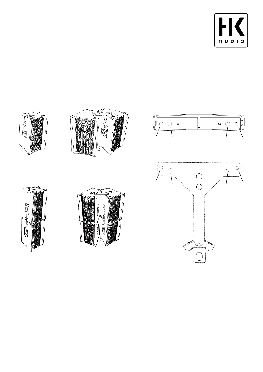
CP Art. no. 6000227
PP Art. no. 6000226
30° Cluster Single
30° Cluster
Single
30° ClusterSingle
30° Cluster
Single
PP/CP Set Art. No. 1007525
2x Pick Point / 2x Cluster Plate
for LINEAR 5 LTS / LTS A
Installation Instructions / Montageanleitung 1.0
PP Art. no. 6000226
Single
Head-Stack Head-Stack Cluster
• Please read these instructions before
installation and keep them for later
reference.
• Heads up: Be sure to observe all the
applicable regulations for installation to
ceilings, walls and trusses.
Cluster
30° ClusterSingle
30° Cluster Single
CP Art. no. 6000227
Single
30° Cluster
30° Cluster
Single
• Bitte vor Gebrauch lesen und für
späteren Gebrauch aufbewahren!
• Wichtig! Die geltenden Vorschriften für
die Montage an Decken, Wänden oder
Trägern sind unbedingt zu beachten.
Made in Germany
Page 2
1 2 3
SingleHead-StackCluster
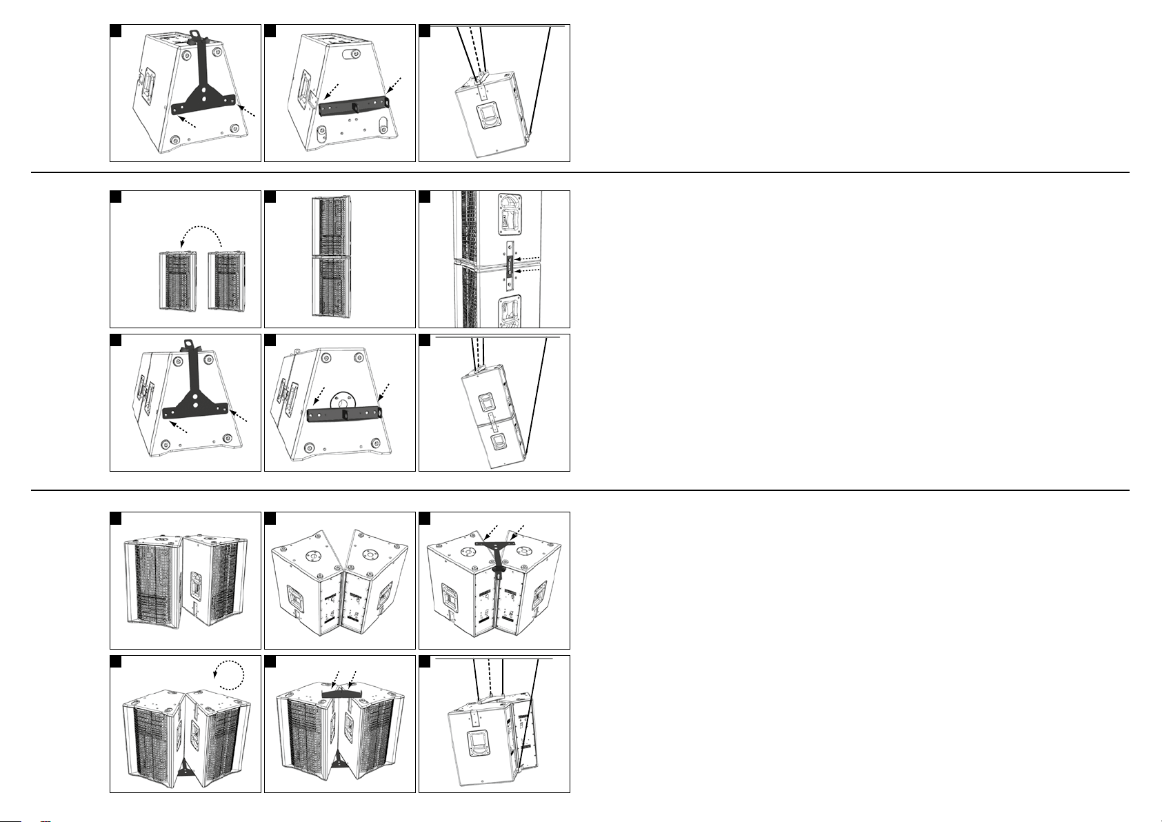
1. Place the cabinet face down on a stable base before
mounting any hardware.
2. Use a 5 mm hex key or the proper bit on a cordless
screwdriver to remove the two countersunk M8
screws from the bottom and top panels.
3. Attach the cluster plate to the bottom and the pick-
point to the top of the cabinet by inserting these
M8 countersink screws into the holes and tightening
them down (refer to the cover sheet).
1. Vor Montage die Box mit der Vorderseite auf einen
sicheren Untergrund legen.
2. Auf Unter- und Oberseite die beiden M8-Senk-
schrauben mittels 5 mm-Innensechskant-Schlüssel
oder Schrauberbit herausdrehen.
3. Auf der Unterseite der Box die Clusterplatte und auf
der Oberseite den Pick-Point mit den zuvor ent fernten
M8-Senkschrauben befestigen (s. Deckblatt).
1
4
1
4
2
5
2
5
3
6
3
6
1. Set the bottom cabinet on a stable base.
2. Turn the upper cabinet on its head and place it top
side down on the lower cabinet.
3. Use a 5 mm hex key or the proper bit on a cordless
screwdriver to remove the thumbscrews (four per
side) along with the washers from the countersunk
panels on each side. Then use the LTS slide rails to
connect the cabinets, fastening them down on both
sides with two thumbscrews and two washers each.
4. Attach the pick-point and cluster plate, following
steps 1 to 3 in the instructions for a single cabinet.
• You now have two and three anchor points,
respectively, for flying a single cabinet or head stack.
1. Place the two cabinets top down on a secure base and
align the cluster.
2.Use a 5 mm hex key or the proper bit on a cordless
screwdriver to remove the interior M8 countersink
screws.
3. Place the cluster plate in the proper position for
mounting, setting the rubber bumpers on the sheet
metal panels at the rear of the cabinets. Insert the M8
countersink screws through the appropriate openings
(refer to the cover sheet) into the tapped holes, and
then tighten them down to attach the cluster plate
(figure 3). This keeps the cabinets from sliding apart
and sets the proper 30° angle of splay for the cluster.
4. Set the connected cabinets upright, bottom down,
and use a 5 mm hex key or the proper bit on a cordless
screwdriver to remove the interior M8 countersink
screws (figure 4).
5. Attach the pick-point by inserting the M8 countersink
screws into the tapped holes and tightening them
down (figure 5).
1. Die untere Box auf einen sicheren Untergrund stellen
2. Die obere Box um 180° gedreht mit dem Deckel auf
die untere Box stellen
3. In den seitlichen Fräsungen die Rändelschrauben
(4 Stück je Seite) samt Unterlegscheiben
mittels 5mm-Innensechskant-Schlüssel oder
Schrauberbit herausdrehen. Die Boxen mittels
der LTS-Schiebebleche auf beiden Seiten mit
je 2 Rändelschrauben und 2 Unterlegescheiben
fest verbinden. Die restlichen Rändelschrauben
und Unterlegscheiben in den freien Gewinden
verschrauben.
4. Pick-Point und Clusterplatte montieren (siehe Single:
Punkt 1 bis 3)
• Für die Single- bzw. Headstack-Anwendung stehen
nun zwei, respektive drei Anschlagpunkte für den
Flugbetrieb zur Verfügung.
1. Die beiden Boxen mit der Oberseite auf einen sicheren
Untergrund stellen und als Cluster ausrichten.
2. Die inneren M8-Senkschrauben mittels 5 mm-Innensechskant-Schlüssel oder Schrauberbit herausdrehen.
3. Die Clusterplatte für die Befestigung positionieren.
Die Gummi-Bumper liegen dabei auf den Blechen der
Gehäuserückseiten auf. Die Clusterplatte mittels der
M8-Senkschrauben durch die entsprechenden Bohrungen (s. Deckblatt) in den freien Gewindelöchern
verschrauben (Abb.3). Hierdurch wird ein Verrutschen
der Boxen verhindert und ein korrekter horizontaler
Önungswinkel von 30° gewährleistet.
4. Die verbundenen Boxen auf die Unterseiten stellen
und die inneren M8-Senkschrauben mittels 5mmInnensechskant-Schlüssel oder Schrauberbit
herausdrehen (Abb.4).
5. Den Pick-Point mittels der M8-Senkschrauben in den
freien Gewindelöchern verschrauben (Abb.5).
Page 3

CP Art. no. 6000227
PP Art. no. 6000226
30° Cluster Single
30° Cluster
Single
30° ClusterSingle
30° Cluster
Single
1
2
3
4
5
Head-Stack Cluster
1. Connect two cabinets using a cluster plate, following
steps 1 to 3 in the instructions for a cluster.
2. Set the connected cabinets upright, bottom down,
and connect them to two more cabinets to stack
them head to head, following steps 4 and 5 in the
instructions for a head stack.
3. Attach the pick-point to the tops of the cabinets, fol-
lowing steps 4 and 5 in the instructions for a cluster.
• You now have two and three anchor points, respec-
tively, for flying a cluster or head-stack cluster.
• If you wish to stack the cluster/head-stack cluster
on a subwoofer with an M20 sleeve, you can do so by
screwing a suitable M20 bolt through the hole at the
center of the cluster plate.
6
1. Zwei Boxen zum Cluster mittels Clusterplatte verbinden (siehe Cluster: Punkt 1 bis 3)
2. Die verbunden Boxen auf die Unterseite stellen und
mit zwei weiteren Boxen zum vertikalen Headstack
verbinden (siehe Headstack 1.-3.)
3. Den Pick-Point auf den Boxen-Oberseiten montieren
(siehe Cluster: Punkt 4 und 5)
• Für die Cluster- bzw. Headstack-Cluster-Anwendung
stehen nun zwei, respektive drei Anschlagpunkte für
den Flugbetrieb zur Verfügung.
• Die Lochung in der Mitte der Clusterplatte erlaubt
das Sichern eines Clusters bzw. Headstack-Clusters
beim Aufbau auf Subwoofer mit M20-Gewindeflansch
mittels passender M20-Schrauben.
The combination of pick-point (PP) and cluster plate (CP) has a
workload limit (WLL) of up to 210 kg at a safety factor of 5.
The maximum permissible load in jurisdictions where the
German BGV-C1 safety code applies is therefore 105 kg.
Der Verbund aus Pick-Point (PP) und Clusterplatte (CP) ist mit
bis zu 210 kg WLL belastbar, bei einem Sicherheitsfaktor von 5.
Im Geltungsbereich der BGV-C1 beträgt somit die zulässige
Belastbarkeit bis zu 105 kg.
984024 8 D-287 3
HK Audio ®
Pos tfach 1509
6659 5 St . Wend el/Ger many
inf o@hkau dio.c om
www .hkaud io.co m
Int ernati onal Inqui ries:
fax +49- 68 51- 905 2 15
int ernati onal@ hkaud io.com
 Loading...