

Page 1

English
Deutsch
Français
Español
Manual 1.1
Page 2

Important Safety Instructions
Before connecting, read instructions
Important Advice on Safety!
Please read before use and keep for later use!
Wichtige Sicherheitshinweise!
Bitte vor Gebrauch lesen und für späteren Gebrauch
aufbewahren!
• Read all of these instructions!
• Save these instructions for later use!
• Follow all warnings and instructions marked on the product!
• Do not use this product near water, i.e. bathtub, sink, swimming pool,
wet basement, etc.
• Do not place this product on an unstable cart, stand or table. The product
may fall, causing serious damage to the product or to persons!
• Slots and openings in the cabinet and the back or bottom are provided for
ventilation; to ensure reliable operation of the product and to protect it from
overheating, these openings must not be blocked or covered. This product
should not be placed in a built-in installation unless proper ventilation is
provided.
• This product should not be placed near a source of heat such as a stove,
radiator, or another heat producing amplifier.
• Use only the supplied power supply or power cord. If you are not sure of the
type of power available, consult your dealer or local power company.
• Do not allow anything to rest on the power cord. Do not locate this product
where persons will walk on the cord.
• Never break off the ground pin on the power supply cord.
• Power supply cords should always be handled carefully. Periodically check
cords for cuts or sign of stress, especially at the plug and the point where the
cord exits the unit.
• The power supply cord should be unplugged when the unit is to be unused for
long periods of time.
• If this product is to be mounted in an equipment rack, rear support should be
provided.
• This product should be used only with a cart or stand that is recommended by
HK AUDIO®.
• Never push objects of any kind into this product through cabinet slots as they
may touch dangerous voltage points or short out parts that could result in
risk of fire or electric shock. Never spill liquid of any kind on the product.
• Do not attempt to service this product yourself, as opening or removing
covers may expose you to dangerous voltage points or other risks. Refer all
servicing to qualified service personnel.
• Clean only with dry cloth.
• Do not defeat the safety purpose of the polarized or grounding-type plug.
A polarized plug has two blades with one wider than the other. A grounding
type plug has two blades and a third grounding prong. The wide blade or the
third prong are provided for the safety. If the provided plug does not fit into
your outlet, consult an electrician for replacement of the obsolete outlet.
• Place the product always in a way that the mains switch is easily accessible.
• Unplug this product from the wall outlet and refer servicing to qualified service personnel under the following conditions:
• When the power cord or plug is damaged or frayed.
• If liquid has been spilled into the product.
• If the product has been exposed to rain or water.
• If the product does not operate normally when the operating instructions are
followed.
• If the product has been dropped or the cabinet has been damaged.
• If the product exhibits a distinct change in performance, indicating a need of
service!
• Adjust only these controls that are covered by the operating instructions since
improper adjustment of other controls may result in damage and will often
require extensive work by a qualified technician to restore the product to
normal operation.
• Exposure to extremely high noise levels may cause a permanent hearing loss.
• Individuals vary considerably in susceptibility to noise induced hearing loss,
but nearly everyone will lose some hearing if exposed to sufficiently intense
noise for a sufficient time. The U.S. Government´s Occupational Safety and
Health Administration (OSHA) has specified the following permissible noise
level exposures:
Duration Per Day In Hours Sound LeveldBA, Slow Response
8 90
6 92
4 95
3 97
2 100
11/2 102
1 105
1/2 110
1/4 or less 115
• According to OSHA, any exposure in excess of the above permissible limits
could result in some hearing loss.
• Ear plug protectors in the ear canals or over the ears must be worn when operating this amplification system in order to prevent a permanent hearing loss if
exposure is in excess of the limits as set forth above. To ensure against potentially dangerous exposure to high sound pressure levels, it is recommended
that all persons exposed to equipment capable of producing high sound
pressure levels such as this amplification system be protected by hearing
protectors while this unit is in operation.
• Fuses: Replace with IEC 127 (5x 20 mms) type and rated fuse for best
performance only.
TO PREVENT THE RISK OF FIRE AND SHOCK HAZARD, DO NOT EXPOSE
THIS APPLIANCE TO MOISTURE OR RAIN. DO NOT OPEN CASE; NO USER
SERVICE-ABLE PARTS INSIDE. REFER SERVICING TO QUALIFIED SERVICE
PERSONNEL.
Version 1.1 11/2006
• The unit has been built by HK AUDIO® in accordance with IEC 60065 and
left the factory in safe working order. To maintain this condition and ensure
non-risk operation, the user must follow the advice and warning comments
found in the operating instructions. The unit conforms to Protection Class 1
(protectively earthed).
• HK AUDIO® ONLY GUARANTEE THE SAFETY, RELIABILITY AND
EFFICIENCY OF THE UNIT IF:
• Assembly, extension, re-adjustment, modifications or repairs are carried out
by HK AUDIO® or by persons authorized to do so.
• The electrical installation of the relevant area complies with the requirements
of IEC (ANSI) specifications.
• The unit is used in accordance with the operating instructions.
• The unit is regularly checked and tested for electrical safety by a competent
technician.
WARNING:
• If covers are opened or sections of casing are removed, except where this can
be done manually, live parts can become exposed.
• If it is necessary to open the unit this must be insulated from all power
sources. Please take this into account before carrying out adjustments, maintenance, repairs and before replacing parts.
• The appliance can only be insulated from all power sources if the mains
connection is unplugged.
• Adjustment, maintenance and repairs carried out when the unit has been
opened and is still live may only be performed by specialist personnel who are
authorized by the manufacturer (in accordance with VBG 4) and who are aware of the associated hazards.
• Loudspeaker outputs which have the IEC 417/5036 symbol (Diagram 1, below)
can carry voltages which are hazardous if they are made contact with. Before
the unit is switched on, the loudspeaker should therefore only be connected
using the lead recommended by the manufacturer.
• Where possible, all plugs on connection cables must be screwed or locked
onto the casing.
• Replace fuses only with IEC127 type and specified ratings.
• It is not permitted to use repaired fuses or to short-circuit the fuse holder.
• Never interrupt the protective conductor connection.
• Surfaces which are equipped with the "HOT" mark (Diagram 2, below), rear
panels or covers with cooling slits, cooling bodies and their covers, as well as
tubes and their covers are purposely designed to dissipate high temperatures
and should therefore not be touched.
• High loudspeaker levels can cause permanent hearing damage. You should
therefore avoid the direct vicinity of loudspeakers operating at high levels.
Wear hearing protection if continuously exposed to high levels.
MAINS CONNECTION:
• The unit is designed for continuous operation.
• The set operating voltage must match the local mains supply voltage.
• The unit is connected to the mains via the supplied power unit or power
cable.
• Power unit: Never use a damaged connection lead. Any damage must be rectified by a competent technician.
• Avoid connection to the mains supply in distributor boxes together with several other power consumers.
• The plug socket for the power supply must be positioned near the unit and
must be easily accessible.
PLACE OF INSTALLATION:
• The unit should stand only on a clean, horizontal working surface.
• The unit must not be exposed to vibrations during operation.
• Place the product always in a way that the mains switch is easily accessible.
• Keep away from moisture and dust where possible.
• Do not place the unit near water, baths, wash basins, kitchen sinks, wet areas,
swimming pools or damp rooms. Do not place objects containing liquid on
the unit - vases, glasses, bottles etc.
• Ensure that the unit is well ventilated.
• Any ventilation openings must never be blocked or covered. The unit must
be positioned at least 20 cm away from walls. The unit may only be fitted in a
rack if adequate ventilation is ensured and if the manufacturer's installation
instructions are followed.
• Keep away from direct sunlight and the immediate vicinity of heating elements and radiant heaters or similar devices.
• If the unit is suddenly moved from a cold to a warm location, condensation
can form inside it. This must be taken into account particularly in the case of
tube units. Before switching on, wait until the unit has reached room temperature.
• Accessories: Do not place the unit on an unsteady trolley, stand, tripod, base
or table. If the unit falls down, it can cause personal injury and itself become
damaged. Use the unit only with the trolley, rack stand, tripod or base recommended by the manufacturer or purchased together with the unit. When
setting the unit up, all the manufacturer's instructions must be followed and the
setup accessories recommended by the manufacturer must be used. Any combination of unit and stand must be moved carefully. A sudden stop, excessive
use of force and uneven floors can cause the combination of unit and stand to
tip over.
• Additional equipment: Never use additional equipment which has not been
recommended by the manufacturer as this can cause accidents.
• To protect the unit during bad weather or when left unattended for prolonged
periods, the mains plug should be disconnected. This prevents the unit being
damaged by lightning and power surges in the AC mains supply.
Diagram 1 Diagram 2
• Das Gerät wurde von HK AUDIO® gemäß IEC 60065 gebaut und hat das
Werk in sicherheitstechnisch einwandfreiem Zustand verlassen. Um diesen
Zustand zu erhalten und einen gefahrlosen Betrieb sicherzustellen, muss
der Anwender die Hinweise und die Warnvermerke beachten, die in der
Bedienungsanleitung enthalten sind. Das Gerät entspricht der Schutzklasse I
(schutzgeerdet).
• DIE SICHERHEIT, ZUVERLÄSSIGKEIT UND LEISTUNG DES GERÄTES WIRD
VON HK AUDIO® NUR DANN GEWÄHRLEISTET, WENN:
• Montage, Erweiterung, Neueinstellung, Änderungen oder Reparaturen von
HK AUDIO® oder von dazu ermächtigten Personen ausgeführt werden.
• die elektrische Installation des betreffenden Raumes den Anforderungen von
IEC (ANSI)-Festlegungen entspricht.
• das Gerät in Übereinstimmung mit der Gebrauchsanweisung verwendet wird.
WARNUNG:
• Wenn Abdeckungen geöffnet oder Gehäuseteile entfernt werden, außer wenn
dies von Hand möglich ist, können Teile freigelegt werden, die Spannung
führen.
• Wenn ein Öffnen des Gerätes erforderlich ist, muss das Gerät von allen Spannungsquellen getrennt sein. Berücksichtigen Sie dies vor dem Abgleich, vor
einer Wartung, vor einer Instandsetzung und vor einem Austausch von Teilen.
• Ein Abgleich, eine Wartung oder eine Reparatur am geöffneten Gerät unter
Spannung darf nur durch eine vom Hersteller autorisierte Fachkraft (nach
VBG 4) geschehen, die mit den verbundenen Gefahren vertraut ist.
• Lautsprecher-Ausgänge, die mit dem IEC 417/5036-Zeichen (Abb.1, s.unten)
versehen sind können berührungsgefährliche Spannungen führen. Deshalb
vor dem Einschalten des Gerätes Verbindung nur mit dem vom Hersteller
empfohlenen Anschlusskabel zum Lautsprecher herstellen.
• Alle Stecker an Verbindungskabeln müssen mit dem Gehäuse verschraubt
oder verriegelt sein, sofern möglich.
• Es dürfen nur Sicherungen vom Typ IEC 127 und der angegebenen Nennstromstärke verwendet werden.
• Eine Verwendung von geflickten Sicherungen oder Kurzschließen des Halters
ist unzulässig.
• Niemals die Schutzleiterverbindung unterbrechen.
• Oberflächen, die mit dem "HOT"-Zeichen (Abb.2, s.unten) versehen sind,
Rückwände oder Abdeckungen mit Kühlschlitzen, Kühlkörper und deren Abdeckungen, sowie Röhren und deren Abdeckungen können im Betrieb erhöhte
Temperaturen annehmen und sollten deshalb nicht berührt werden.
• Hohe Lautstärkepegel können dauernde Gehörschäden verursachen.
Vermeiden Sie deshalb die direkte Nähe von Lautsprechern, die mit hohen
Pegeln betrieben werden. Verwenden Sie einen Gehörschutz bei dauernder
Einwirkung hoher Pegel.
NETZANSCHLUSS:
• Das Gerät ist für Dauerbetrieb ausgelegt.
• Die eingestellte Betriebsspannung muss mit der örtlichen Netzspannung
übereinstimmen.
• Der Anschluss an das Stromnetz erfolgt mit dem mitgelieferten Netzteil oder
Netzkabel.
• Netzteil: Eine beschädigte Anschlussleitung kann nicht ersetzt werden.
Das Netzteil darf nicht mehr betrieben werden.
• Vermeiden Sie einen Anschluss an das Stromnetz in Verteilerdosen zusammen mit vielen anderen Stromverbrauchern.
• Die Steckdose für die Stromversorgung muss nahe am Gerät angebracht und
leicht zugänglich sein.
AUFSTELLUNGSORT:
• Das Gerät sollte nur auf einer sauberen, waagerechten Arbeitsfläche stehen.
• Das Gerät darf während des Betriebs keinen Erschütterungen ausgesetzt sein.
• Feuchtigkeit und Staub sind nach Möglichkeit fernzuhalten.
• Das Gerät muss immer so aufgestellt werden, dass der Netzschalter frei zugänglich ist.
• Das Gerät darf nicht in der Nähe von Wasser, Badewanne, Waschbecken,
Küchenspüle, Nassraum, Swimmingpool oder feuchten Räumen betrieben
werden. Keine mit Flüssigkeit gefüllten Gegenstände -Vase, Gläser, Flaschen
etc. auf das Gerät stellen.
• Sorgen Sie für ausreichende Belüftung der Geräte.
• Eventuelle Ventilationsöffnungen dürfen niemals blockiert oder abgedeckt
werden. Das Gerät muss mindestens 20 cm von Wänden entfernt aufgestellt
werden. Das Gerät darf nur dann in ein Rack eingebaut werden, wenn für
ausreichende Ventilation gesorgt ist und die Einbauanweisungen des Herstellers eingehalten werden.
• Vermeiden Sie direkte Sonneneinstrahlung sowie die unmittelbare Nähe von
Heizkörpern und Heizstrahlern oder ähnlicher Geräte.
• Wenn das Gerät plötzlich von einem kalten an einen warmen Ort gebracht
wird, kann sich im Geräteinnern Kondensfeuchtigkeit bilden. Dies ist insbesondere bei Röhrengeräten zu beachten. Vor dem Einschalten solange warten
bis das Gerät Raumtemperatur angenommen hat.
• Zubehör: Das Gerät nicht auf einen instabilen Wagen, Ständer, Dreifuß,
Untersatz oder Tisch stellen. Wenn das Gerät herunterfällt, kann es Personenschäden verursachen und selbst beschädigt werden. Verwenden Sie das Gerät
nur mit einem vom Hersteller empfohlenen oder zusammen mit dem Gerät
verkauften Wagen, Rack, Ständer, Dreifuß oder Untersatz. Bei der Aufstellung
des Gerätes müssen die Anweisungen des Herstellers befolgt und muss das
vom Hersteller empfohlene Aufstellzubehör verwendet werden. Eine Kombination aus Gerät und Gestell muss vorsichtigt bewegt werden. Plötzliches
Anhalten, übermäßige Kraftanwendung und ungleichmäßige Böden können
das Umkippen der Kombination aus Gerät und Gestell bewirken.
• Zusatzvorrichtungen: Verwenden Sie niemals Zusatzvorrichtungen, die nicht
vom Hersteller empfohlen wurden, weil dadurch Unfälle verursacht werden
können
• Zum Schutz des Gerätes bei Gewitter oder wenn es längere Zeit nicht beaufsichtigt oder benutzt wird, sollte der Netzstecker gezogen werden.
Dies verhindert Schäden am Gerät aufgrund von Blitzschlag und Spannungsstößen im Wechselstromnetz.
Abb.1 Abb.2
Page 3

Conseils de Securite Importants!
Priere de lire avant l'emploi et a conserver pour
utilisation ulterieure!
Importanti avvertimenti di sicurezza!
Leggere attentamente prima dell'uso e conservare
per un utilizzo successivo:
¡Indicaciones de seguridad importantes!
¡Léanse antes de utilizar el aparato y guardense para
so uso posterior!
• L'appareil a été conçu par HK AUDIO® selon la norme IEC 60065 et a quitté
l'entreprise dans un état irréprochable. Afin de conserver cet état et d'assurer
un fonctionnement sans danger de l'appareil nous conseillons à l'utilisateur
la lecture des indications de sécurité contenues dans le mode d'emploi.
L'appareil est conforme à la classification I (mise à terre de protection).
• SURETE, FIABILITE ET EFFICACITE DE L'APPAREIL NE SONT GARANTIS
PAR HK AUDIO® QUE SI:
• Montage, extension, nouveau réglage, modification ou réparation sont
effectués par HK AUDIO® ou par toute personne autorisée par
HK AUDIO®.
• L'installation électrique de la pièce concernée correspond aux normes IEC
(ANSI).
• L'utilisation de l'appareil suit le mode d'emploi.
AVERTISSEMENT:
• A moins que cela ne soit manuellement possible, tout enlèvement ou ouverture du boîtier peut entrainer la mise au jour de pieces sous tension.
• Si l'ouverture de l'appareil est nécessaire, celui-ci doit être coupé de chaque
source de courant. Ceci est à prendre en considération avant tout ajustement,
entretien, réparation ou changement de pieces.
• Ajustement, entretien ou réparation sur l'appareil ouvert et sous tension
ne peuvent être éffectués que par un spécialiste autorisé par le fabricant
(selon VBG4). Le spécialiste étant conscient des dangers liés à ce genre de
réparation.
• Les sorties de baffles qui portent le signe IEC 417/5036 (fig. 1, voir en bas)
peuvent être sous tension dangereuse. Avant de brancher l'appareil utiliser
uniquement le câble de raccordement conseillé par le fabricant pour raccorder les baffles.
• Toutes les prises des câbles de raccordement doivent être, si possible, vissées
ou verrouillées sur le boîtier.
• L’utilisation de fusibles rafistolés ou court-circuites est inadmissible
– seulement: IEC127.
• L'utilisation de fusibles rafistolés ou court-circuites est inadmissible.
• Ne jamais interrompre la connexion du circuit protecteur.
• Il est conseillé de ne pas toucher aux surfaces pourvues du signe "HOT" (fig.
2, voir en bas), aux parois arrières ou caches munis de fentes d'aération,
éléments d'aération et leurs caches ansi qu'aux tubes et leurs caches.
Ces éléments pouvant atteindre des températures élévées pendant
l'utilisation de l'appareil.
• Les Niveaux de puissance élévés peuvent entrainer des lésions auditives
durables. Evitez donc la proximité de haut-parleurs utilisés à haute puissance.
Lors de haute puissance continue utilisez une protection auditive.
BRANCHEMENT SUR LE SECTEUR:
• L'appareil est conçu pour une utilisation continue.
• La tension de fonctionnement doit concorder avec la tension secteur locale.
• Le raccordement au réseau éléctrique s'effectue avec l'adaptateur ou le
cordon d´alimentation livré avec l'appareil.
• Adaptateur: Un câble de raccordement abimé ne peut être remplacé.
L'adaptateur est inutilisable.
• Evitez un raccordement au réseau par des boîtes de distribution surchargées.
• La prise de courant doit être placée à proximité de l'appareil et facile à
atteindre.
LIEU D'INSTALLATION:
• L'appareil doit être placé sur une surface de travail propre et horizontale.
• L'appareil en marche ne doit en aucun cas subir des vibrations.
• Posez l'appareil en place de sorte que l'interrupteur du réseau reste accessible facilement.
• Evitez dans la mesure du possible poussière et humidité.
• L'appareil ne doit pas être placé à proximité d'eau, de baignoire, lavabo, évier,
pièce d'eau, piscine ou dans une pièce humide. Ne placez aucun vase, verre,
bouteille ou tout objet rempli de liquide sur l'appareil.
• L'appareil doit être suffisamment aéré.
• Ne jamais recouvrir les ouvertures d'aération. L'appareil doit être placé à 20
cm du mur au minimum. L'appareil peut être monté dans un Rack si une
ventilation suffisante est possible et si les conseils de montage du fabricant
sont suivis.
• Evitez les rayons de soleil et la proximité de radiateurs, chauffages etc.
• Une condensation d'eau peut se former dans l'appareil si celui-ci est transporté brusquement d'un endroit froid à un endroit chaud. Ceci est particulièrement important pour des appareils à tubes. Avant de brancher l'appareil
attendre qu'il ait la température ambiante.
• Accessoires: L'appareil ne doit être placé sur un chariot, support, trépied,
bâti ou table instable. Une chute de l'appareil peut entrainer aussi bien des
dommages corporels que techniques. Utilisez l'appareil uniquement avec un
chariot, Rack, support, trépied ou bâti conseillé par le fabricant ou vendu en
combinaison avec l'appareil. Les indications du fabricant pour l'installation
de l'appareil sont à suivre, et les accessoires d'installation conseillés par le
fabricant sont à utiliser. Un ensemble support et appareil doit être déplacé
avec précaution.
Des mouvements brusques et des revêtements de sol irreguliers peuvent
entrainer la chute de l´ensemble.
• Equipements supplémentaires: Ne jamais utiliser un équipement supplémentaire n'ayant pas été conseillé par le fabricant, ceci pouvant entrainer des
accidents.
• Afin de protéger l'appareil pendant un orage ou s'il ne doit pas être utilisé
pendant un certain temps, il est conseillé d'enlever la prise au secteur.
Ceci évite des dommages dûs à la foudre ou à des coups de tension dans le
réseau à courant alternatif.
Fig. 1 Fig. 2
• L'apparecchio è stato costruito dalla HK AUDIO® secondo la normativa
europea IEC 60065 ed ha lasciato il nostro stabilimento in stato ineccepibile.
Per garantire il mantenimento di tale stato e un utilizzo assolutamente privo
di rischi l'utente è tenuto ad osservare le indicazioni e gli avvertimenti di sicurezza contenuti nelle istruzioni per l'uso. L'apparecchio rispecchia il livello di
sicurezza I (collegato a terra).
• Sicurezza, affidabilità e prestazioni dell'apparecchio vengono garantiti dalla
HK AUDIO® solo ed esclusivamente se:
• Montaggio, ampliamento, rimessa a punto, modifiche e riparazioni vengono
eseguite dalla HK AUDIO® stessa o da personale da essa autorizzato.
• Gli impianti elettrici nei locali prescelti per l'uso dell'apparecchio rispondono
alle normative stabilite dall'ANSI.
• L'apparecchio viene utilizzato come indicato nel libretto delle istruzioni per
l'uso.
AVVERTIMENTI:
• In caso di apertura di parti di rivestimento o rimozione di parti dell'involucro,
a meno che non si tratti di pezzi rimovibili semplicemente a mano, possono
venire alla luce parti dell'apparecchio conduttrici di tensione.
• Se l'apertura dell'apparecchio dovesse risultare necessaria è indispensabile
staccare precedentemente quest'ultimo da tutte le fonti di tensione. Rispettare tale misura di prevenzione anche prima di un allineamento, di operazioni
di manutenzione, della messa in esercizio o della sostituzione di componenti
all'interno dell'apparecchio.
• Allineamento, operazioni di manutenzione o eventuali riparazioni
dell'apparecchio in presenza di tensione vanno eseguite esclusivamente da
personale specializzato ed autorizzato, in grado di eseguire tali operazioni
evitandone i rischi connessi.
• Le uscite degli altoparlanti contrassegnate dai caratteri IEC 417/5036 (vedi
illustrazione 1 a fondo pag.) possono essere conduttrici di tensione pericolosa con cui evitare il contatto. Per questo motivo, prima di accendere
l'apparecchio, collegare quest'ultimo agli altoparlanti servendosi esclusivamente del cavetto d'allacciamento indicato dal produttore.
• Tutte le spine e i cavi di collegamento devono essere avvitati o fissati
all'involucro dell'apparecchio per quanto possibile.
• Utilizzare esclusivamente fusibili del tipo IEC 127 con la indicata corrente
nominale.
• L'utilizzo di fusibili di sicurezza non integri e la messa in corto circuito del
sostegno di metallo sono proibite.
• Non interrompere mai il collegamento con il circuito di protezione.
• Superfici contrassegnate dalla parola "HOT" (vedi illustrazione 2 a fondo
pag.), cosi come griglie di aerazione, dispositivi di raffreddamento e i loro
rivestimenti di protezione, oppure valvole e i relativi rivestimenti protettivi
possono surriscaldarsi notevolmente durante l'uso e per questo motivo non
vanno toccate.
• L'ascolto di suoni ad alto volume può provocare danni permanenti all'udito.
Evitate perciò la diretta vicinanza con altoparlanti ad alta emissione di suono
e utilizzate cuffie protettive in caso ciò non sia possibile.
ALIMENTAZIONE:
• L'apparecchio è concepito per il funzionamento continuo.
• La tensione di esercizio deve corrispondere alla tensione di rete a cui ci si
allaccia.
• L'allacciamento alla rete elettrica avviene tramite alimentatore o cavetto
d'alimentazione consegnato insieme all'apparecchio.
• Alimentatore: un cavo di connessione danneggiato non può essere sostituito.
L'alimentatore non può più essere utilizzato.
• Evitate un allacciamento alla rete di corrente utilizzando cassette di distribuzione sovraccariche.
• La spina di corrente deve essere situata nelle vicinanze dell'apparecchio e
facilmente raggiungibile in qualsiasi momento.
LOCALI DI COLLOCAMENTO:
• Opportuno collocare l'apparecchio su una superficie pulita e orizzontale.
• Non sottoporre l'apparecchio in funzione a scosse e vibrazioni.
• L’apparecchio deve essere posizionato sempre in modo da assicurare il libero
accesso all’interruttore di alimentazione.
• Proteggere l'apparecchio per quanto possibile da umidità e polvere.
• Non collocare l'apparecchio vicino ad acqua, vasche da bagno, lavandini,
lavelli da cucina, locali umidi o piscine. Non appoggiare recipienti contenenti
liquidi - vasi, bicchieri, bottiglie, ecc. - sull'apparecchio.
• Provvedere ad una buone aerazione dell'apparecchio.
• Eventuali aperture previste per la ventilazione dell'apparecchio non vanno
ne bloccate, ne mai coperte. L'apparecchio va collocato ad almeno 20 cm di
distanza dalle pareti circostanti e può essere inserito tra altre componenti di
un impianto solo in caso di sufficiente ventilazione e qualora le direttive di
montaggio del produttore vengano rispettate.
• Evitare di esporre l'apparecchio ai raggi del sole e di collocarlo direttamente
nelle vicinanze di fonti di calore come caloriferi, stufette, ecc.
• Se l'apparecchio viene trasportato rapidamente da un locale freddo ad
uno riscaldato può succedere che al suo interno si crei della condensa. Ciò
va tenuto in considerazione soprattutto in caso di apparecchi a valvole.
Attendere che l'apparecchio abbia assunto la temperatura ambiente prima di
accenderlo.
• Accessori: non collocare l'apparecchio su carrelli, supporti, treppiedi, superfici
o tavoli instabili. Se l'apparecchio dovesse cadere a terra potrebbe causare
danni a terzi o danneggiarsi irreparabilmente. Utilizzate per il collocamento
dell'apparecchio supporti, treppiedi e superfici che siano consigliate dal
produttore o direttamente comprese nell'offerta di vendita. Per il collocamento dell'apparecchio attenetevi strettamente alle istruzioni del produttore,
utilizzando esclusivamente accessori da esso consigliati. L'apparecchio in
combinazione ad un supporto va spostato con molta attenzione.
Movimenti bruschi o il collocamento su pavimenti non piani possono provocare la caduta dell'apparecchio e del suo supporto.
• Accessori supplementari: non utilizzate mai accessori supplementari che non
siano consigliati dal produttore, potendo essere ciò causa di incidenti.
• Per proteggere l'apparecchio in caso di temporali o nel caso questo non venisse utilizzato per diverso tempo si consiglia di staccarne la spina di corrente.
In questo modo si evitano danni all'apparecchio dovuti a colpi di fulmine o ad
improvvisi aumenti di tensione nel circuito di corrente alternata.
Illustrazione 1 Illustrazione 2
• El aparato ha sido producido por HK AUDIO® según el IEC 60065 y salió de
la fábrica en un estado técnicamente perfecto. Para conservar este estado y
asegurar un funcionamiento sin peligros el usuario debe tener en cuenta las
indicaciones y advertencias contenidas en las instrucciones de manejo.
El aparato corresponde a la clase de protección l (toma de tierra protegida).
• LA SEGURIDAD, LA FIABILIDAD Y EL RENDIMIENTO DEL APARATO SOLO
ESTAN GARANTIZADOS POR HK AUDIO® CUANDO:
• el montaje, la ampliación, el reajuste, los cambios o las reparaciones se
realicen por HK AUDIO® o por personas autorizadas para HK AUDIO®;
• la instalación eléctrica del recinto en cuestión corresponda a los requisitos
de la determinación del IEC (ANSI);
• el aparato se use de acuerdo con las indicaciones de uso.
ADVERTENCIA:
• Si se destapan protecciones o se retiran piezas de la carcasa, exceptuando si
se puede hacer manualmente, se pueden dejar piezas al descubierto que sean
conductoras de tensión.
• Si es necesario abrir el aparato, éste tiene que estar aislado de todas las
fuentes de alimentación. Esto se debe tener en cuenta antes del ajuste, de un
entretenimiento, de una reparación y de una sustitución de las piezas.
• Un ajuste, un entretenimiento o una reparación en el aparato abierto y bajo
tensión sólo puede ser llevado a cabo por un especialista autorizado por el
productor (según VBG 4) que conozca a fondo los peligros que ello conlleva.
• Las salidas de altavoces que estén provistas de la característica IEC 417/5036
(figura 1, véase abajo) pueden conducir tensiones peligrosas al contacto. Por
ello es indispensable que antes de poner en marcha el aparato; la conexión
se haya realizado únicamente con el cable de empalmes recomendado por el
productor.
• Las clavijas de contacto al final de los cables conectores tienen que estar
atornilladas o enclavadas a la carcasa, en tanto que sea posible.
• Sólo se pueden utilizar fusibles del tipo IEC 127 con la intensidad de corriente
nominal indicada.
• El uso de fusibles reparados o la puesta en cortocircuito del soporte es
inadmisible.
• El empalme del conductor de protección no se puede interrumpir en ningún
caso.
• Las superficies provistas de la característica "HOT" (figura 2, véase abajo),
los paneles de fondo trasero o las protecciones con ranuras de ventilación,
los cuerpos de ventilación y sus protecciones, así como las válvulas electrónicas y sus protecciones pueden alcanzar temperaturas muy altas durante el
funcionamiento y por ello no se deberían tocar.
• Niveles elevados de la intensidad de sonido pueden causar continuos daños
auditivos; por ello debe evitar acercarse demasiado a altavoces que funcionen
a altos niveles. En tales casos utilice protecciones auditivas.
ACOMETIDA A LA RED:
• El aparato está proyectado para un funcionamiento continuo.
• La tensión de funcionamiento ajustada tiene que coincidir con la tensión de
la red del lugar.
• La conexión a la red eléctrica se efectuará con la fuente de alimentación o con
el cable de red que se entreguen con el aparato.
• Fuente de alimentación: una linea de conexión dañada no se puede sustituir.
La fuente de alimentación no puede volver a ponerse en funcionamiento.
• Evite una conexión de la red eléctrica a distribuidores con muchas tomas de
corriente.
• El enchufe para el suministro de corriente tiene que estar cerca del aparato
y ser de fácil acceso.
SITUACION:
• El aparato debería estar situado en una superficie limpia y totalmente horizontal.
• El aparato no puede estar expuesto a ningún tipo de sacudidas durante su
funcionamiento.
• Coloque el dispositivo de forma que el interruptor de la red quede accessible
facilmente.
• Se deben evitar la humedad y el polvo.
• El aparato no puede ponerse en funcionamiento cerca del agua, la bañera, el
lavamanos, la pila de la cocina, un recinto con tuberías de agua, la piscina o
en habitaciones húmedas. Tampoco se pueden poner objetos llenos de líquido - jarrones, vasos, botellas, etc. - encima de él.
• Procure que el aparato tenga suficiente ventilación.
• Las aberturas de ventilación existentes no se deben bloquear ni tapar nunca.
El aparato debe estar situado como mínimo a 20 cm de la pared. El aparato
sólo se puede montar en un rack, si se ha procurado la suficiente ventilación
y se han cumplido las indicaciones de montaje del productor.
• Evite los rayos del sol directos así como la proximidad a radiadores, electro radiadores o aparatos similares.
• Si el aparato pasa repentinamente de un lugar frío a otro caliente, se puede
condensar humedad en su interior. Esto se debe tener en cuenta sobretodo
en los aparatos con válvulas electrónicas. Antes de poner en marcha el aparato se debe esperar hasta que éste haya adquirido la temperatura ambiental.
• Accesorios: el aparato no se puede colocar encima de carros, estantes,
trípodes, soportes o mesas inestables. Si el aparato se cae puede causar
daños perso nales y se puede estropear. Coloque el aparato sólo en un carro,
rack, estante, trípode o soporte recomendado por el productor o que se
le haya vendido junto con el aparato. En la instalación se deben seguir las
indicaciones del productor así como utilizar los accesorios recomendados
por el mismo para colocarlo encima. El conjunto del aparato con el pedestal
se debe mover con mucho cuidado. Un paro brusco, la aplicación de una
fuerza desmesurada o un suelo irregular puede ocasionar la caida de todo el
conjunto.
• Piezas adicionales: no utilice nunca piezas adicionales que no estén recomendadas por el productor, ya que se podrían provocar accidentes.
• Para protejer el aparato de una tormenta o si no se supervisa ni utiliza
durante algún tiempo, se debería desconectar la clavija de la red. Así se
evitan daños en el aparato a causa de un rayo y golpes de tensión en la red de
corriente alterna.
Figura 1 Figura 2
Page 4
FIRNET Controller 1.1
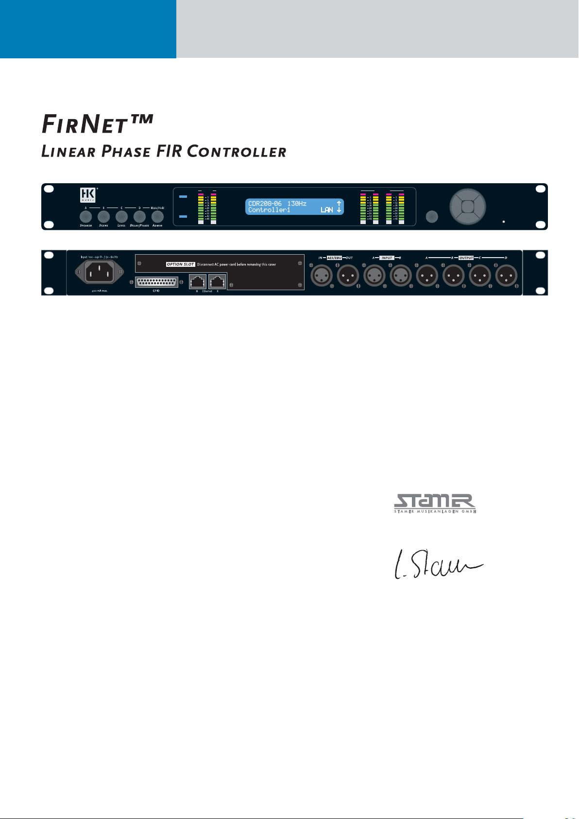
FirNet™
Linear Phase FIR Controller
OutputsInputs
aes
sync
dB
BA
MuteLim LimOVL
dB
dB
BA
DC
Back Reset
Congratulations!
You made an excellent choice by opting for the
HK AUDIO FIRNETLinear Phase Controller.
The HK AUDIO engineers who developed the
FIRNET controller dipped into a deep well of more
than ten years experience working with FIR fi ltering
technology, developing state-of-art AD/DA converters, and programming digital signal processors.
Designed to handle with the greatest ease, this
device helps you effi ciently distribute and process
audio signals to achieve excellent audio results with
our speaker systems.
Please read this manual carefully; your time will
be well-spent as this information will help you
make the most of the device and its performance
potential.
This manual describes the FIRNET controller’s
functions in great detail. If you are knowledgeable
of and experienced with this type of controller and
simply need a quick introduction to the front panel
and its functions, you may wish to consult the
Quick Start Guide on page 6.
Important Notes on Safety
Please read carefully the following instructions
and safety guidelines, and keep them safe for later
reference. Be sure to heed all the cautionary notes
and follow the instructions.
• Do not remove covers; there are no user-serviceable parts inside. Please refer all servicing and
maintenance to qualifi ed service personnel.
• Ensure this device is grounded.
• Position the mains cord so it cannot be stepped
on or pinched, particularly at the plug end, at
power outlets, and at the point it exits the device.
• Use this device only with attachments and accessories specifi ed by the manufacturer.
• This device must be serviced if damaged in any
way, for example, if the mains cord or plug is damaged, liquids are spilled or objects dropped into
the device, or if it is exposed to rain or moisture,
dropped, or fails to operate normally.
This is to certify that
HK Audio FirNet™
complies with the provisions of the Directive of the
Council of the European Communities on the approximation of the laws of the Member States relating to
electromagnetic compatibility according to EMC directive 2004/108/EC and low voltage directive 2006/95/EC.
This declaration of conformity of the European Communities is the result of an examination carried out by
the Quality Assurance Department of STAMER GmbH
in accordance with European Standards EN61000-6-1,
EN61000-6-2, and EN 60065 for low voltage.
Magdeburger Str. 8, 66606 St. Wendel
Lothar Stamer Dipl.Ing.
Managing Director
St. Wendel, 08/08/2008
Version 2.0 08/2008
Page 5

Table of contents:
1 Purpose ...........................................................................................................................................................6
2 Quick Start Guide ...........................................................................................................................................6
Display, Menu Keys, Channel Mute
3 General Features .............................................................................................................................................6
3.1 FIR ................................................................................................................................................................... 6
3.2 State-of-the-Art Digital Converters ................................................................................................................... 6
3.3 Sophisticated Limiters ..................................................................................................................................... 6
3.4 Network Enabled ............................................................................................................................................. 6
3.5 Wireless Freedom ............................................................................................................................................ 6
3.6 GPIO/Option Slot – Ready for Various Extensions ............................................................................................7
4 LIPAN PC Software for Remote Control and Monitoring .................................................................................. 7
4.1 Fundamentals ..................................................................................................................................................7
4.2 IP Address ........................................................................................................................................................7
4.3 Database of Filter Sets for Specifi c Speakers .....................................................................................................7
4.4 Total Control .....................................................................................................................................................7
4.5 Fast Access .......................................................................................................................................................7
4.6 Grouping Controllers ........................................................................................................................................7
4.7 Database of Scenes for Specifi c Events .............................................................................................................7
4.8 Stereo Controller EQ .........................................................................................................................................7
5
5 Front - Control Readouts and Displays ............................................................................................................8
6 Rear Panel Connectors ...................................................................................................................................9
7 Menu Options ................................................................................................................................................11
7.1 A General Survey of Menu Options .................................................................................................................11
7.2 A General Survey of Control Keys .................................................................................................................... 11
7.3 Start Menu - Viewing Current Settings ............................................................................................................ 11
7.4 Adjusting Parameters ..................................................................................................................................... 11
7.4.1 Selecting Speakers .......................................................................................................................................... 11
7.4.2 Scenes - Loading and Saving Previously Stored Settings ................................................................................ 12
7.4.3 Adjusting Levels .............................................................................................................................................. 12
7.4.4 Delay/Phase .................................................................................................................................................... 12
7.4.5. Admin - Adjusting the Remaining Parameters ................................................................................................. 13
7.4.5.1 Key Lock – Preventing Unauthorized Access ...................................................................................................13
7.4.5.2 Input Options ................................................................................................................................................. 13
7.4.5.3 Utilities: Delay, Temperature, Display Contrast, Controller Name ...................................................................14
7.4.5.4 Analog Levels .................................................................................................................................................. 14
7.4.5.5 Muting Outputs .............................................................................................................................................. 15
7.5 Firmware ........................................................................................................................................................ 15
8 Technical Data ................................................................................................................................................15
English
Page 6

FIRNET Controller 1.1
1 Purpose
The FIRNET controller performs digitally all functions required to address, control, and remote-control HK AUDIO sound reinforcement systems, that
is, speakers and amps. Featuring advanced AD and
DA converter technology and an internal sampling
rate of 96 kHz, it is a premium-quality audio signal
processing tool.
2 Quick Start Guide
Display
The LCD shows information on presets and parameters. The default readout appears after the device is
powered up, and then the display indicates current
speaker selection settings and the LAN status. Once
you begin navigating adjustable parameters, it
shows values pertaining to these parameters.
Menu Keys
Menu keys (Speaker, Level, Scene, Delay/Phase
und Admin) serve to access the various parameter
sections. You can adjust the indicated parameters
and save these settings using the edit select keys
(cursors and back key) for the selected input and
output. Pressing the back key always takes you to
the next higher menu level.
Note: The device retains stored values even if a
power failure occurs or it is unplugged from the
mains supply.
Channel Mute
• Using Channel Mute Shortcuts to Mute Outputs
A/B/C/D
You can use combinations of the Admin menu key
and the four other menu keys (Speaker, Scene,
Level, Delay/Phase) to mute the FIRNET’s output
channels in A/B/C/D sequence. For example, if you
wish to mute output A, press Admin + Speaker;
to mute output D, press Admin + Delay/Phase.
Press the same combination again to reactivate the
output.
Note: Each of the output channels’ red signal LEDs
show the given output’s mute status (constant red
= MUTE).
3 General Features
• FIR fi lters ensure phase accuracy and strikingly
natural-sounding response.
• Top-drawer converter technology provides outstanding dynamic range up to 130 dB (A/D)
• Sophisticated limiters feature an advanced design.
• 96-kHz internal sampling rate delivers highest
resolution and transparency.
• Ethernet ports serve to network devices.
• Ethersound, CobraNet, and other interfaces may
be retrofi tted.
• GPIO interface on board.
• LIPAN PC software enables remote monitoring.
3.1 FIR
FIR (Finite Impulse Response) fi ltering technology
provides total phase linearity across all components
(speakers, controllers, amps), enabling you to
equalize a sound systems’ frequency response and
phase (or group delay) separately. Thus the system
renders the different frequency ranges of a sonic
image coherently; that is, in time and faithfully.
Differences in phase response no longer cause listening fatigue, dramatically improving transparency
and three-dimensional imaging.
Unlike IIR (Infi nite Impulse Response) fi lters,
FIR fi lters do not consist of a specifi c number of
separately computed fi lter elements. Instead, they
contain a complete sampled copy, with the magnitude and phase function required for equalization.
The FIR fi lters in the FIRNET controller equalize all
components of the HK AUDIO sound reinforcement
systems, including the speaker chassis, speaker
enclosures, passive crossovers, power amps, and
the controller itself.
Earlier FIR controllers suffered the drawback of high
latency. The FIRNET controller for the fi rst time
exploits the benefi ts of FIR fi lters at the low latency
previously confi ned to conventional IIR controllers.
This means you can even use FIR technology for
monitoring applications, where it delivers far more
gain before feedback.
Optimized IIR fi lters are used to achieve very
low latency no higher than 5.8 ms, including
FIR fi ltering.
3.2 State-of-the-Art Digital
Converters
The FIRNET controller sports a high-end digital
converter and audio DSPs usually found in reference-class studio gear. They deliver excellent sound
quality and dynamic response, with a dynamic range
up to 130 dB (A/D).
3.3 Sophisticated Limiters
Limiters must protect speakers without squeezing
the life out of the sonic image. All the FIRNET
controller’s outputs are equipped with peak and
RMS limiters. The peak limiters look ahead to anticipate amps’ output power. In case of an eminent
overload, they attenuate this output to levels the
speaker systems are rated to handle.
The sophisticated combination of look-ahead (2ms) peak limiters and RMS limiters with discretely
adjusted threshold, attack, hold, and release times
ensure the system operates safely.
Note: Adjust the following settings to ensure the
FIRNET operates properly with the given power
amps:
When using FP10000Q amps:
Gain LAB: + 26 dBu
Max D/A Level FIRNET (Admin view): + 18 dBu
When using VX 2400 amps:
Gain VX: + 35 dBu
Max A/D level FIRNET (Admin view): +6 dBu
3.4 Network Enabled
The FIRNET controller ships with Ethernet interfaces (cross-connected signal input (X) and parallel
input (II) on the back of the device), and integrates
into a LAN via TCP/IP.
3.5 Wireless Freedom
A wireless network access point enables wireless
communication at live events. You can send every
adjustment made on a laptop or tablet PC direct to
the controllers across a wireless network from any
point in the auditorium.
Page 7
3.6 GPIO/Option Slot – Ready
for Various Extensions
The GPIO interface provides a universal connection that could, for example, link with the house
system’s control unit. The Option slot accepts
future extension hardware such as CobraNet ports
and Ethersound interfaces, ensuring your investment in FIRNET yields long-term returns on your
investment.
4 LIPAN PC Software for Remote Control and
Monitoring
4.3 Database of Filter Sets for
Specific Speakers
The FIRNET features an extendible database
archiving functions for equalization, phase
correction, and power handling capacity specifi cations of different HK AUDIO speakers and sound
reinforcement systems.
The controller stores up to 100 fi lters tuned for
specifi c speakers. A simple mouse click adds setups
to and removes setups from the fi lter database. The
database lists these speaker-specifi c fi lters by their
HK AUDIO speaker series names for easy access.
4.1 Fundamentals
FIRNET LIPAN software runs on WIN XP and
enables you to remotely monitor and control
anything from a single controller to an audio
network comprising up to 100 devices, and all this
with remarkable clarity and convenience. It handles
so intuitively that you’ll be able to achieve great
results the fi rst time out! The standard Ethernet
X and II ports on the rear panel let you connect
several FIRNET controllers to remotely control and
monitor entire networks. For details on network
cable connections, see chapter 6.3, „Rear Panel, PC
Ethernet Control Ports.“
With a connected PC running LIPAN software, you
can then remote-control this network; that is, monitor all parameters set and indicated at the FIRNET
and adjust all controller settings at your PC. LIPAN
software also performs further convenient functions
such as simultaneously manipulating several FIRNET controllers assigned to groups and equalizing
the entire system with a fully parametric IIR-EQ for
every controller. Read the LIPAN software manual to
learn more about what it can do for you.
4.2 IP Address
Every device has a predefi ned IP address that may
be edited at the device. Every controller in the
network is identifi ed and addressed individually by
its freely assignable name and unique IP address.
Controllers are integrated via a LAN or WLAN.
All settings may be stored to the PC as a backup,
ensuring they remain accessible at any time.
4.4 Total Control
The main window provides a clear view of every
networked setup, including all connected controllers and confi gured groups. A simple mouse click
in the network view selects any controller or group
for editing.
4.5 Fast Access
The desktop offers a channel strip view of all the
controller’s functions called the controller window.
A mouse click changes speaker fi lters, levels, mute
and solo groups, and phases in real-time, without
a lot of searching and thumbing through operating
manuals. The Admin menu clearly lists all parameters such as IP-address, controller name, and audio
source, as well as units for temperature, delay, and
the like.
4.6 Grouping Controllers
Several controllers may be grouped in 16 different
groups, making it easy to adjust parameters such as
levels and delay times collectively. The main window
affords a clear view of all routings.
4.7 Database of Scenes for
Specific Events
The FIRNET features a database with ten memory
slots for setups for specifi c events called scenes.
They are handy tools for recurring events at the
same venues because the speed up audio system
setup and ensure every event benefi ts from the
same high quality of audio performance.
7
4.8 Stereo Controller EQ
LIPAN also provides also an IIR stereo EQ with
four fully parametric and two multifunctional
bands (peak, shelf, and cut) for every controller in
the network. They serve to equalize and adapt the
system to suit the given venue. You can set up a
WLAN link to check settings at different positions in
the audience area and adjust them immediately in
real time via this online link.
English
Page 8

FIRNET Controller 1.1
5 Front - Control Readouts and Displays:
1 SPEAKER Key
• Selects a speaker-specifi c fi lter set from the FIRNET speaker series database
2 SCENE Key
• Loads scenes setups from the FIRNET database
and stores them to the database
3 LEVEL Key
• Adjusts input and output levels in the range of -60
dB to 12 dB
• Increment = 0.1 dB in the range of 12 dB to -12 dB
• Increment = 0.5 dB below -12 dB
4 DELAY/PHASE Key
• Adjusts delay time up to 500 ms for the FIRNET
controller’s inputs
• Adjusts delay time up to 25 ms for the FIRNET
controller’s outputs
• Inverts the phase position of the audio signal routed to the FIRNET controller’s inputs and outputs
5 ADMIN Key
• Locks keys to prevent unauthorized or unintentional handling
• Selects the audio signal input and associated
options
• Adjusts peak analog input and output levels to
match FIRNET to upstream or downstream audio
devices
• Edits the IP address, controller name, and display
contrast
• Serves to select the delay unit of measure
(ms, m, ft, samples) and enter the surrounding
temperature to calculate the speed of sound
6 AES IN LED Display
• Lights up blue when the FIRNET controller’s
digital AES/EBU IN signal input is selected
• Extinguished when the FIRNET’s analog signal
inputs are selected
7 EXT SYNC LED Display
• This LED lights up blue when an external AES/EBU
signal is enabled for the FIRNET’s synchronization
option and the device receives an incoming signal.
• Extinguished when the controller’s internal synchronization is selected
8 INPUT LED Displays (10 LEDs, green/yellow/red)
• Green segment: Audio input level in the range of
-48 to -12 dB at full scale
• Yellow segment: Audio input level in the range of
-12 to 0 dB at full scale
• Red segment: Audio input level is overdriving the
AD converter
Note: An overdriven AD converter generates
distortion that the FIRNET’s limiter cannot suppress. If the red LED lights up, set the FIRNET’s
input gain to a higher value (see the section Setting
Peak AD Level in the Adjusting Parameters chapter)
or reduce the source audio device’s output level!
Be sure to heed the gain level recommendations for
connected amps, particularly when operating an
FP10000Q power amp.
9 LCD
• 2 x 24 characters
• Shows in normal operating mode the controller
name, the selected fi lter, and the existence of a
network link
• Shows options and editable parameters when you
access a menu
10 OUTPUT LED Displays
(10 LEDs, green/yellow/red)
• Green segment: Audio input level in the range of
-48 to -12 dB below the limiter value
• Yellow segment: Audio input level in the range of
-12 to 0 dB at below the limiter value
• Red segment: Limiter is attenuating the audio
input level. The given output is muted (LED lights
up continuously)
11 Back Key
• Returns to the next higher menu level
• Exits edit windows without assigning adjusted
values
• Adopts unconfi rmed parameter changes with Enter
12 Navigation Keys
• Navigates to the next or previous menu option
• Selects and changes parameters in the edit
windows
• Top key: Arrow up while scrolling in the menus
• Bottom key: Arrow down while scrolling in the
menus
• Right key to adjust parameter values (higher
numerical values)
• Left key to adjust parameter values (lower
numerical values)
• Enter key to confi rm the adjusted value
13 Reset Button
The FIRNET controller reboots after 10 seconds,
and then loads the most recent settings. Unsaved
settings are not retained.
14 Soft Reset and Hard Reset key combinations
The FIRNET offers two more reset functions:
Soft Reset: (Admin+Back+Enter for 3 seconds)
Loading the default preset Null
Functions:
• No speaker/ no fi lter selected
• No signal routed to the exits
• All FIR initial coeffi cients set to 0
• No fi lters set; fi lter must be reloaded!
• X-Over set to bypass
• Input/ output gain set to 0
• Delay parameter set to 0
• IIR EQs all input gains set to 0,
• IIR EQs output set to bypass (LIPAN Off) and gain to 0
• All limiters set to + 10dB threshold
• Admin parameters remain unchanged
• Outputs 1-4 muted
Hard Reset: Factory default
(Speaker+Admin+Back for 3 seconds)
Functions:
• Filter banks deleted
• Admin: Keylock deactivated
• Input assign A/B
• Analog input source
• Sample rate 96 kHz
• Dig Clk Sync: internal
• Delay unit: ms
• Temperature: 20°C
• Display contrast: 15
• Device name 0
• Max input: + 18 dBu
• Max. output + 6 dBu (setting for VX 2400)
• IP not reset
Page 9
6 Rear Panel Connectors
9
1 100-240 V~ / 50-60 Hz Mains
This three-pole non-heating equipment connector
with a ground contact connects the FIRNET controller to the mains power supply. The multi-voltage power supply unit allows the controller to be connected directly to all mains voltages ranging between
100 V and 240 V without requiring transformers
and the like. Its maximum power consumption is 40
VA, which corresponds to about 175 mA maximum
current consumption at 230 V mains voltage and
about 400 mA at 100 V. Do not connect the device
using anything other than a three-pole connector
with a ground contact. The mains outlet must also
be equipped with a ground contact. Never use
damaged cords, plugs, or sockets.
2 GPIO
This 25-pin sub-D port provides four each fl oating
inputs and outputs for future fi rmware versions’
use, for example, to remote-control power amps or
switch controlled devices. Current fi rmware does
not support this feature.
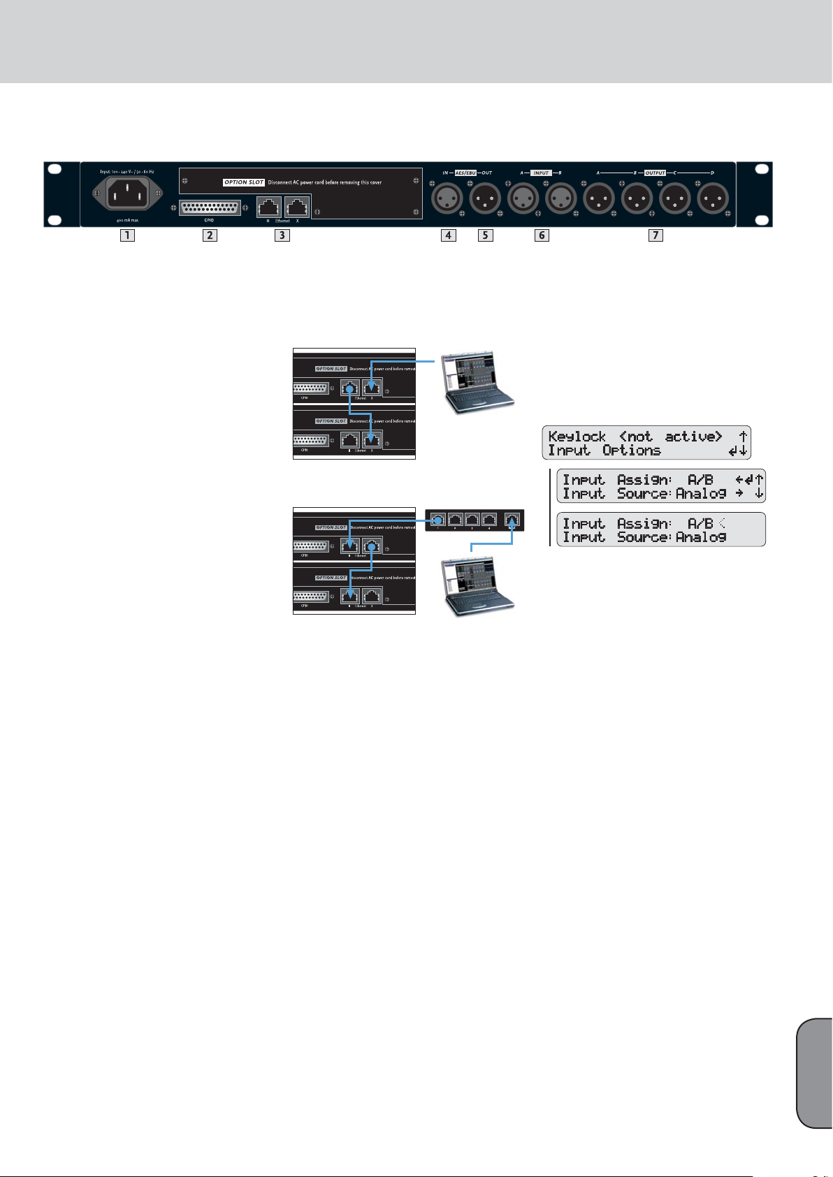
3 Ethernet PC Control Ports
Ethernet ports relay remote control and monitoring
data between a PC and FIRNET controllers via
computer networking hardware. The Ethernet X and
Ethernet II connectors are RJ-45 ports (Input X = for
cross input, II = parallel input).
Cabling:
If you do not wish to use further network hardware such as hubs and switches, connect the PC’s
network port to the fi rst FIRNET’s Ethernet X port
using CAT5 network cable. Then also use a CAT5 network cable to connect the fi rst FIRNET’s Ethernet II
port to the second controller’s Ethernet X port, and
so forth.
Use a CAT5 network cable to connect the FIRNET
controller to hubs or switches, patching the FIRNET
controller’s Ethernet II port to the hub or switch’s
network port. To daisy-chain further FIRNET
controllers, connect the fi rst FIRNET’s Ethernet X
port to the second controller’s Ethernet II port, and
so forth.
Tip: We recommend that you connect all FIRNET
controllers to switches. If you do not, and one controller fails in setups comprising several connected
FIRNET controllers, the entire networked chain will
drop out.
Figure: Networked FIRNET and PC
Figure: Networked hub and PC
4 AES/EBU IN Digital Audio Input
Connect signal sources with digital outputs to these
three-pin female XLR sockets. Pin assignments are
pin 1 = ground, pin 2 = signal, and pin 3 = signal.
The FIRNET controller accepts sampling rates of
48 kHz and 96 kHz, which may be selected via a
menu option.
Input-Output Signal Routing
The analog INPUT A – that is, the left channel of the
digital AES/EBU signal - delivers the signal to OUTPUT A and OUTPUT B. OUTPUT C and OUTPUT D
receive their signal from analog INPUT B, that is,
the right channel of the digital AES/EBU signal. You
can reroute signals in the LIPAN software’s Admin
window.
5 AES/EBU OUT Digital Audio Output
The signal patched into the AES/EBU input can be
routed through in digital format to other devices via
this three-pin male XLR port. Pin assignments are
pin 1 = ground, pins 2 and 3 = signal. The FIRNET
amplifi es the incoming digital audio signal to
preserve signal quality. If a FIRNET controller drops
out, the signal is routed directly from the digital
AES/EBU IN to the digital AES/EBU OUT via a
parallel circuit.
To select the digital input, go to the Admin menu
(press ADMIN once), choose the menu option
Input Options (press the down arrow once), and
then press ENTER to confi rm:
Menu option - ADMIN/Input Options/ Input Source
Synchronization Ports for Analog Audio Signals:
If you wish to address several FIRNET controllers
via their analog inputs, you can use digital AES/EBU
IN inputs and AES/EBU OUT outputs to synchronize these controllers to ensure the audio signal
remains coherent.
To do this, connect the fi rst FIRNET controller’s
digital AES/EBU OUT to the second FIRNET’s
digital AES/EBU IN. Then connect the second FIRNET controller’s digital AES/EBU OUT to the third
FIRNET’s digital AES/EBU IN, and so forth.
Leave the fi rst FIRNET’s digital AES/EBU IN and
the last FIRNET’s digital AES/EBU OUT unoccupied. The fi rst FIRNET is the master, providing the
clock for the other slaved controllers, so access
this FIRNET’s menu function to select the internal
clock. Confi gure the other controllers so they accept
synchronization commands via the AES/EBU signal
and select their analog inputs for the audio signal
using the appropriate menu options.
Note: The Sync LED on subsequent controllers in
the network light up to confirm they are synchronized.
English
Page 10
FIRNET Controller 1.1
6 INPUT A, INPUT B Analog Audio Inputs
Connect signal sources with analog outputs to these
three-pin female XLR sockets. Pin assignments are
pin 1 = ground, pin 2 = signal (+), pin 3 = signal
(-). These electronically balanced ports’ input
impedance is 9 k-ohms. An electronic fi lter protects
them against HF interference.
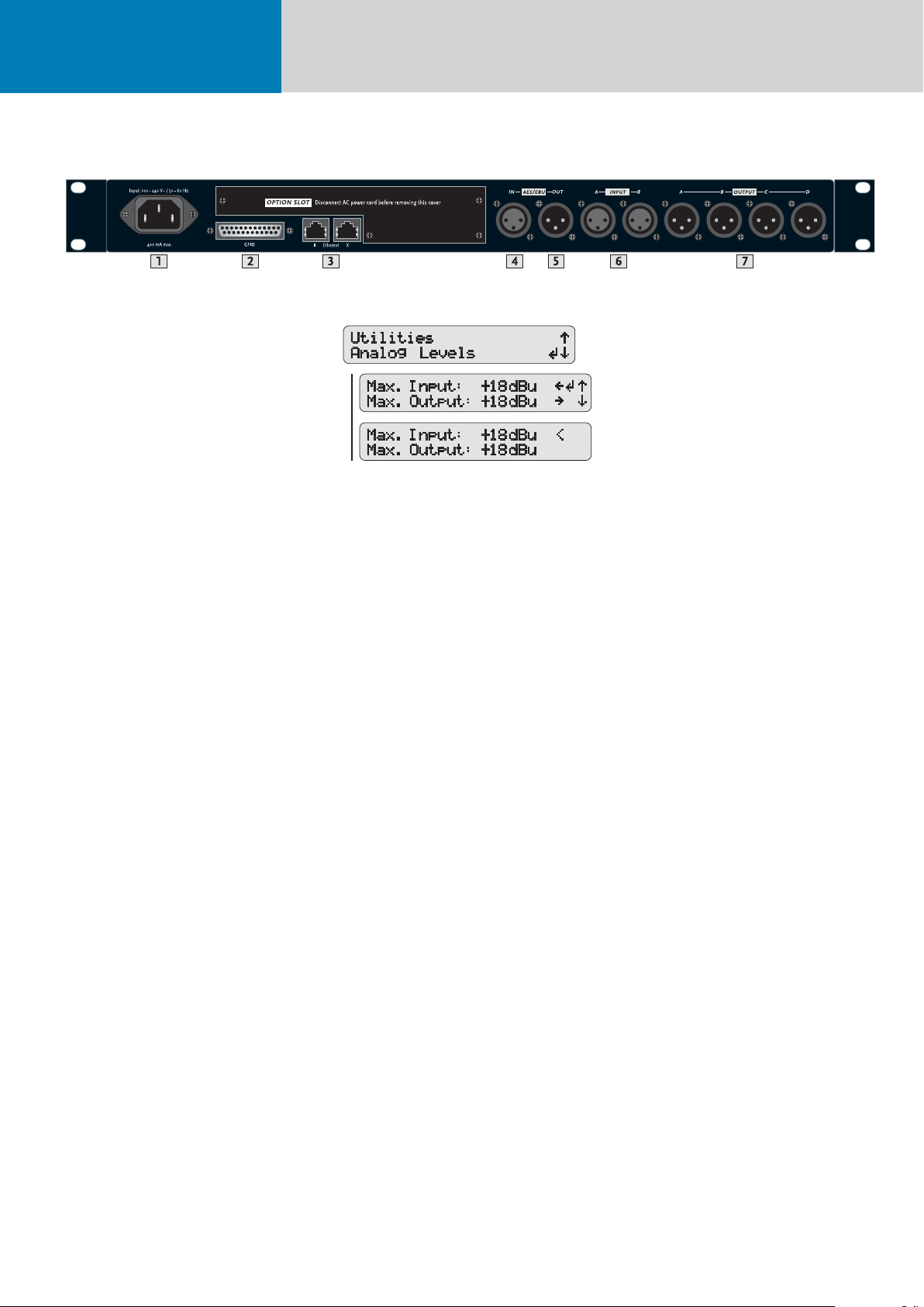
A menu option lets you adjust input sensitivity in
four steps (6 dBu, 12 dBu, 18 dBu, 24 dBu) to match
the FIRNET controller’s input to the connected audio device’s analog output. Proper matching vastly
improves the signal-to-noise ratio at the FIRNET
controller’s analog input.
To match levels, go to the Admin menu (press
ADMIN once), choose the menu option Analog
Levels (press down arrow thrice), and then confi rm
by pressing ENTER.
Menu option - ADMIN/Analog Levels
The FIRNET uses stacked AD converters to achieve
>130 dB (A) input dynamic range.
Note: You must manually set analog levels to
18 dBu after a firmware update (see section 7,
Analog Signal Outputs).
7 OUTPUT A to OUTPUT D Analog Audio Outputs
Use these three-pin XLR male sockets to route
output signals to power amps. Pin assignments
are pin 1 = ground, pin 2 = signal (+), and pin 3 =
signal (-). These electronically balanced connectors’
output impedance is 35 ohms. The DA converters’
output dynamic range is >124 dB (A). A menu
option lets you adjust the maximum output level in
four steps (6 dBu, 12 dBu, 18 dBu, 24 dBu) to match
the levels of the FIRNET controller’s output and the
connected power amp’s analog input.
Note: Adjust the following settings to ensure the
FIRNET operates properly with the given power
amps:
When using FP10000Q amps:
Gain LAB: + 26 dBu
Max D/A Level FIRNET (Admin view): + 18 dBu
When using VX 2400 amps:
Gain VX: + 35 dBu
Max A/D level FIRNET (Admin view): +6 dBu
Page 11
7. Menu Options
11
7.1 A General Survey of Menu Options
Mute Output A/B/C/D
These control keys serve to mute individual outputs.
Simply press and hold the Admin key while pressing
key 1 to 4 to select and mute an output.
7.4 Adjusting Parameters
Controller Menus
Five menu options are available for editing
individual parameters. Simply press the appropriate
key to select a menu.
7.4.1 Selecting Speakers
A quick run-down on how to select the speaker series and the right fi lter for the connected
speaker(s) follows.
7.2 A General Survey of Control Keys
7.3 Start Menu - Viewing Current
Settings
The device begins booting as soon as it is
connected to the mains supply and powered up.
The display fi rst reads TEST, and then a < symbol
wanders across the display. At the end of the boot
sequence, the display indicates the current fi rmware
for about two seconds.
Then the controller’s start menu shows the
following parameters:
• Preset no.
• Controller name and LAN status
• Current IP address
• Current scene
• Current routing
• Routing input
• Current input
• Current sample rate
• Current synchronization status
• Current fi rmware version
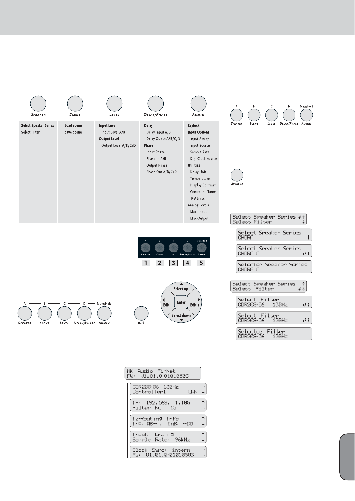
Press the SPEAKER key to select a speaker-specifi c
fi lter set from the FIRNET’s fi lter database and the
keys to choose the menu option Select Spea-
RS
ker Series, if not already selected. Press the ENTER
key to go to the Select Speaker Series submenu
and the S key to choose an HK AUDIO speaker
series. Press the ENTER key to confi rm the selected
speaker series.
Press the SPEAKER key again and the RS keys to
choose the menu option Select Filter (press the S
key once). Press the ENTER key to go to the Select
Filter submenu and the S key to select a speakerspecifi c fi lter set for the previously selected speaker
series. Press the ENTER key to load a selected
speaker-specifi c fi lter set to the FIRNET controller..
English
Page 12
FIRNET Controller 1.1
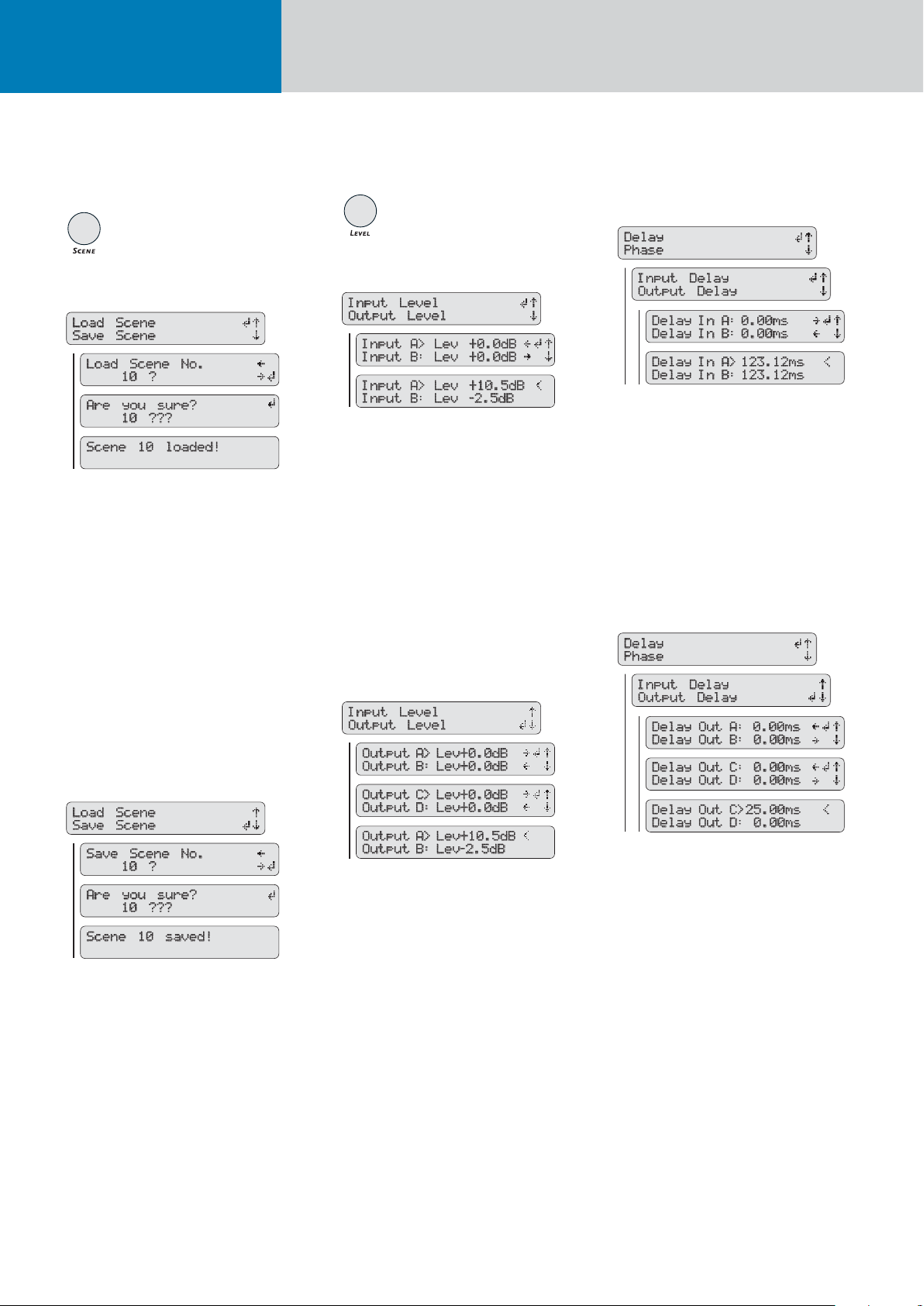
7.4.2 Scenes - Loading and Saving
Previously Stored Settings
Load Scene - Accessing Previously Stored Settings
To load previously created and stored scenes, press
the SCENE key and then the
menu option Load Scene, if not already selected.
Press the ENTER key to go to the Load Scene
submenu and the QP keys to choose the number
of the desired scene from 0 to 9. Press the ENTER
key to load the selected scene. The LCD will issue
a warning reading Different Speaker Series if the
selected scene uses speaker-specifi c fi lter sets other
than those used by the current scene. You must
confi rm by pressing the ENTER key. A confi rmation
prompt then appears in the LCD asking Are you
sure? Confi rm again by pressing the ENTER key.
Scene X appears in the LCD indicating the given
scene has been loaded.
keys to select the
RS
7.4.3 Adjusting Levels
Adjusting Input Levels
Note: The input level refers to the change in the
internal signal processing (post A/D converter),
which affects the output levels (or output level
indication pre D/A converter).
To adjust the signal levels at the FIRNET’s inputs,
press the LEVEL key and then the RS keys to
select the menu option Input Level, if not already
selected. After pressing the ENTER key, use the
keys to select an audio input (Input A or
RS
Input B) and the QP keys to set the desired gain
for this input. Then press the ENTER key to confi rm
and assign this level.
Adjusting Output Levels
7.4.4 Delay/Phase
Adjusting Input Delays
To adjust the delays at the FIRNET’s inputs, press
the DELAY/PHASE key and then the arrow up and
down keys to select the menu option Delay, if not
already selected. Press the ENTER key and then the
keys to select the menu option Input Delay, if
RS
not already selected. After pressing the ENTER key,
use the RS keys to select an audio input (Input
A or Input B) and the QP keys to set the desired
delay within a range of 0 to 500 ms for this input.
Then press the ENTER key to confi rm and assign
this delay setting
Adjusting Output Delays
Save Scene - Storing Settings as a Scene
Once you have confi gured the controller to suit the
venue, you can store the FIRNET’s current setup as
a scene. To do this, press the SCENE key and then
the RS keys to choose the menu option Save
Scene (press the S key once). Press the ENTER key
to go to the Save Scene No submenu and the QP
arrow keys to choose a number from 0 to 9 for the
memory slot in which you wish to store the scene.
Press the ENTER key again to save the scene to the
chosen memory slot. A confi rmation prompt then
appears in the LCD asking Are you sure? Confi rm
again by pressing the ENTER key. Scene X appears
in the LCD indicating you have saved the scene.
To adjust signal levels at the FIRNET’s outputs,
press the LEVEL key and then the RS keys to
select the menu option Output Level (press the S
key once). After pressing the ENTER key, use the
arrow RS keys to select an audio output (Output
A to Output D) and the QP keys to set the desired
gain for this output. Then press the ENTER key to
confi rm and assign this level.
To adjust the delays at the FIRNET’s outputs, press
the DELAY/PHASE key and then the RS keys
to select the menu option Delay, if not already
selected. Press the ENTER key and then the RS
keys to select the menu option Output Delay (press
once). After pressing the ENTER key, use the
S
keys to select an audio output (Output A to
RS
Output D) and the QP keys to set the desired
delay within a range of 0 to 500 ms for this output.
Then press the ENTER key to confi rm and assign
this delay setting.
Page 13
13
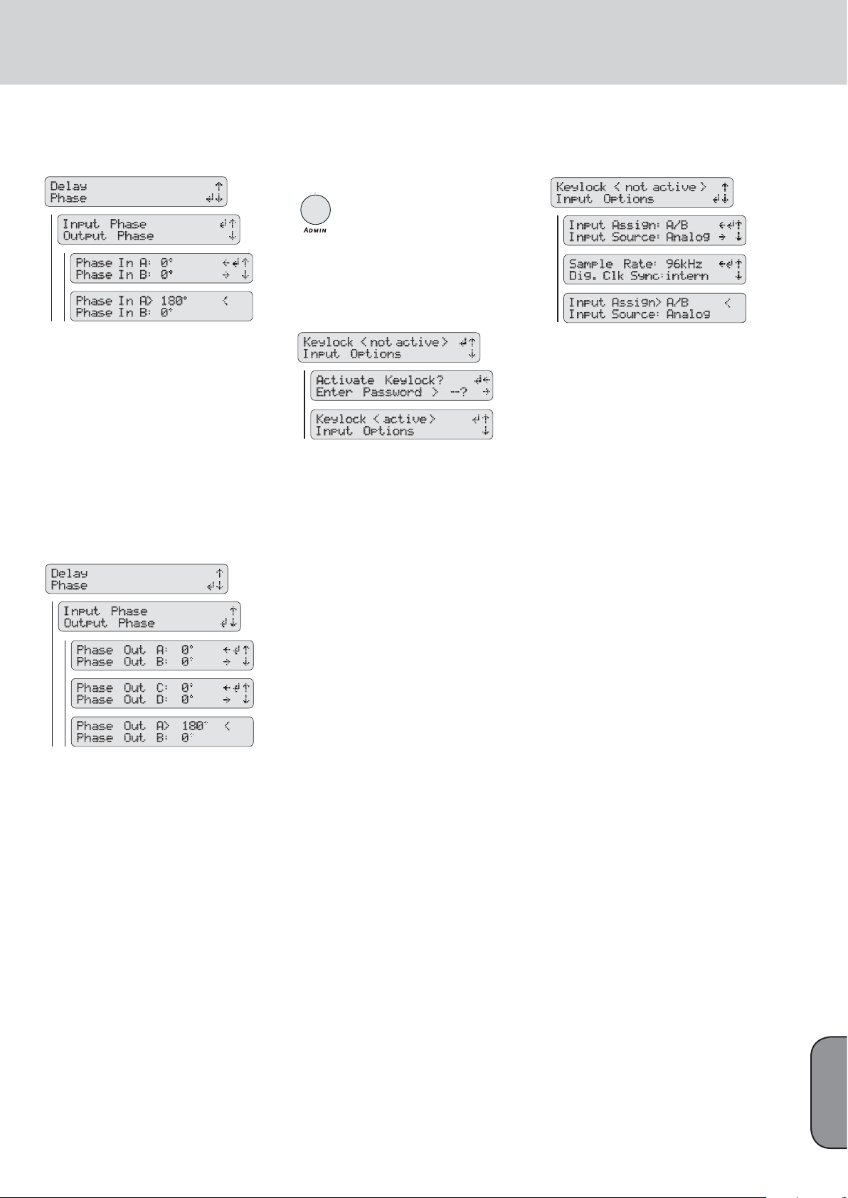
Selecting the Input Phase Position
The FIRNET lets you set each input’s phase position
to 0° or 180° for incoming audio signals. To do this,
press the DELAY/PHASE key and then the RS
keys to select the menu option Phase (press the S
key once). Press the ENTER key and then the RS
keys to select the menu option Input Phase, if not
already selected. After pressing the ENTER key, use
the RS keys to select an audio input (Input A or
Input B) and the QP keys to select the desired
phase position, 0° or 180°, for this input. Then
press the ENTER key to confi rm and assign this
phase position.
Selecting the Output Phase Position
The FIRNET also lets you set each output’s phase
position to 0° or 180° for outgoing audio signals. To
do this, press the DELAY/PHASE key and then the
keys to select the menu option Phase (press
RS
the S key once). Press the ENTER key and then the
keys to select the menu option Output Phase
RS
(press the S key once). After pressing the ENTER
key, use the arrow up and down keys to select an
audio output (Output A to Output D) and the QP
keys to select the desired phase position, 0° or
180°, for this output. Then press the ENTER key to
confi rm and assign this phase position.
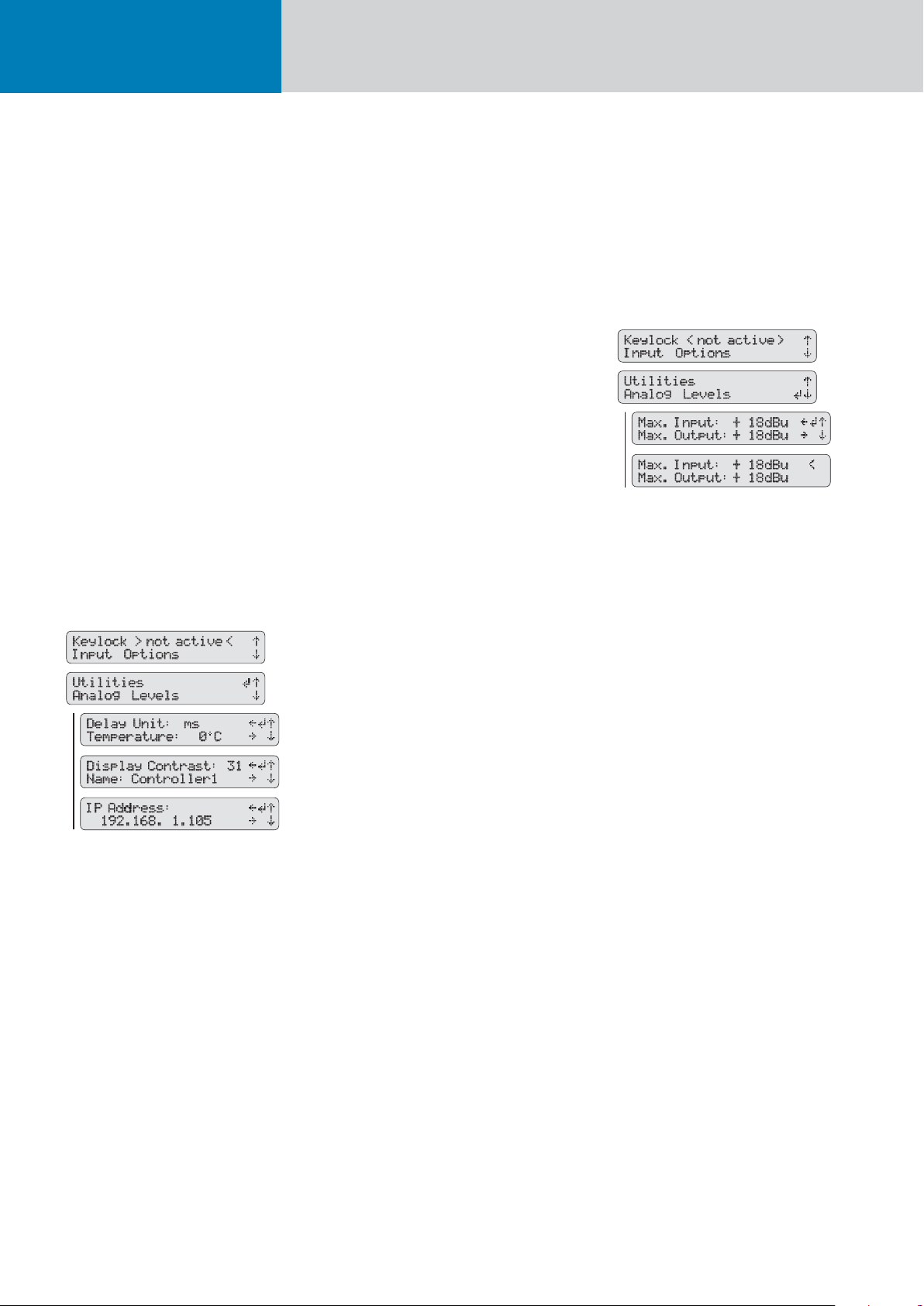
7.4.5. Admin - Adjusting the
Remaining Parameters
7.4.5.1 Key Lock – Preventing
Unauthorized Access
Locking Keys
You can lock the FIRNET controller’s keys to prevent
unauthorized access and unintentional editing. To
lock keys, press the ADMIN key to access the Admin
menu. Use the RS navigation keys to select the
menu option Keylock (if not already selected) and
press the ENTER key. The LCD now reads Activate
Keylock? and prompts you to enter a password (23).
Use the QP navigation keys to select the number
23 and press the ENTER key.
Unlocking Keys
To unlock keys, press the ADMIN key to access
the Admin menu. Keylock is the only menu option
available, so simply press the ENTER key to
confi rm. The LCD now reads Deactivate Keylock?
and prompts you to enter a password. Press the
ENTER key in the key navigation cross to select the
password, which is 23.
Enter the password by pressing the P key, and
then press the ENTER key to unlock the keys. If you
select the wrong password, you will be returned to
the Keylock function’s selection menu.
7.4.5.2 Input Options
Input Assign
• Selecting Separate or Linked Audio Circuits for
Inputs A-B
Access the Admin menu by pressing the ADMIN
key. Use the arrow keys to select the input menu
option Input Options and confi rm your selection
with ENTER. Select A/B or Link for the menu option
Input Assign and confi rm your selection by pressing
the ENTER key.
Input Source
• Selecting an Analog or Digital Input
Access the Admin menu by pressing the ADMIN
key. Use the arrow up and down keys to select the
menu option Input Options (press the arrow down
key once) and press the ENTER key. Now use the
arrow up and down keys to select the submenu option Input Source (press the arrow down key once)
and the left and right arrow keys to select an analog
(Analog) or digital (AES/EBU) input. Then press the
ENTER key to assign the selected input.
Sampling Rate - Digital Clock Source
• Setting the sampling frequency and the digital
AES/EBU input
When addressing the FIRNET via the digital input,
you can chose between two sampling rates, 48 kHz
or 96 kHz, for the digital audio signal. The FIRNET
always works with an internal sampling rate of 96
kHz. If you patch in a digital audio signal with a
48-kHz sampling rate, the FIRNET converts it to
96 kHz.
English
Page 14
FIRNET Controller 1.1
Digital Clock Source
• Synchronizing Analog Circuits
You can chose between two operating modes when
addressing the FIRNET via the analog inputs. The
controller may be synchronized to its internal clock
or an external clock routed in via the AES/EBU
input.
Synchronizing several FIRNET controllers to an external clock ensures individual FIRNET controllers’
audio signals remain coherent. This is particularly
important for speaker confi gurations with coherent
throw patterns such as line arrays.
To select the clock source, fi rst press the ADMIN
key to access the Admin menu. Use the RS keys
to select the menu option Input Options (press the
key once) and press the ENTER key.
S
Now use the RS keys to select the submenu option Dig. Clk Sync (press R once) and the QP keys
to set the FIRNET to Internal or AES/EBU. Then
press the ENTER key to assign the selected clock.
The FIRNET’s display shows the selected source.
7.4.5.3 Utilities: Delay, Temperature,
Display Contrast, Controller
Name
Selecting a Unit of Measure for Delay Readings
The FIRNET indicates delay settings in milliseconds (ms), meters (m), feet (ft), or samples (SA).
To select a unit of measure for the delay display
reading, fi rst press the ADMIN key to access the
Admin menu. Use the RS keys to select the menu
option Utilities (press R or S twice) and press
the ENTER key. Now use the RS keys to select the
submenu option Delay Unit, if not already selected,
and the QP keys to select the desired unit for the
delay display reading. Then press the ENTER key to
assign the selected unit of measure.
To calculate the delay reading for meters (m) and
feet (ft), the FIRNET fi rst computes the milliseconds (ms) value based on the speed of sound,
which depends on temperature. You must enter the
surrounding temperature to the FIRNET to ensure
this value is converted correctly. To do this, fi rst
press the ADMIN key to access the Admin menu.
Use the RS keys to select the menu option Utilities (press R or S twice) and press the ENTER
key. Now use the RS keys to select the submenu
option Temperature (press the S key once) and the
keys to set the current ambient temperature
QP
in °C. Then press the ENTER key to assign this temperature to the equation the FIRNET uses to convert
the unit of measure for the delay display reading.
Adjusting the LCD’s Contrast
To adjust the LCD’s contrast to the given lighting
conditions, fi rst press the ADMIN key to access the
Admin menu. Use the RS keys to select the menu
option Utilities (press R twice or S) and press
the ENTER key. Now use the RS keys to select
the submenu option Display Contrast and the QP
keys to select the desired display contrast within
a range of 0 to 31. Then press the ENTER key to
assign the contrast setting.
Adjusting Temperature
The FIRNET always stores delay values as samples
per ms. It converts the information given at a
sampling frequency of 96 kHz and indicates it
as delay time in ms. The speed of sound, which
varies according to temperature, is a factor in the
conversion equation. This is why you must enter the
correct air temperature to the FIRNET.
Selecting the Controller Name
To create an orderly, logical PA setup, you want
to establish a clear link between a FIRNET and a
speaker or group of speakers. To this end, you can
give a controller a meaningful name such as PA
Left. To change a controller name, fi rst press the
ADMIN key to access the Admin menu. Use the
keys to select the menu option Utilities (press
RS
or S twice) and press the ENTER key. Now use
R
the RS keys to select the submenu option Contr.
Name (press arrow up twice). Use the QP keys
to change each letter of the indicated controller
name. Press ENTER to go to the next letter in the
controller name. Once you have entered the desired
controller name, press the ENTER key for about
two seconds until a < symbol appears next to the
controller name to assign this name.
Changing the IP Address
The FIRNET ships with a default IP address that
reads 192.168.1.100. To change the IP address, fi rst
press the ADMIN key to access the Admin menu.
Use the RS keys to select the menu option
Utilities (press R or S twice) and press the
ENTER key. Now use the RS keys to select the
submenu option IP Address (press R once). Use
theQP keys to change each digit of the indicated
IP address. Press ENTER to go to the next digit in
the IP address. Once you have entered the desired
IP address, press the ENTER key for about two
seconds until a < symbol appears next to the IP
address. To assign the new IP address, you must
power the FIRNET down by severing its connection
to the mains supply. The FIRNET will boot with the
new IP address the next time you power it up.
7.4.5.4 Analog Levels
Adjusting the Maximum Input Level (AD)
When addressing the FIRNET via the analog audio
inputs, you can adjust input sensitivity in four steps
of 6 dBu, 12 dBu, 18 dBu, and 24 dBu to match the
FIRNET controller’s input to the connected audio
device’s analog output. The lower the value, the
higher the input sensitivity and the higher the input
level. To set the maximum level for the AD converter, fi rst press the ADMIN key to access the Admin
menu. Use the navigation keys RS to select the
menu option Analog Levels (press R once) and
press the ENTER key. Now use the navigation keys
to select the submenu option Max. Input and
RS
set the desired maximum level for the AD converter.
Then press the ENTER key to assign the selected
maximum level to the AD converter.
Note: Professional mixing consoles’ output level
can range up to +18 dBu, and in some cases even
up to +24 dBu. The FIRNET is factory set to +18
dBu. Ensure the input level you have selected in this
menu matches as closely as possible the connected
audio device’s maximum output level.
Adjusting the Maximum Output Level (DA)
Adjust the FIRNET’s analog output signal’s
maximum level (Max. Output) to match the
downstream power amp.
Heads up: Correct limiter settings ensure the
FIRNET operates safely with the various power amplifiers that drive HK AUDIO loudspeakers. To this
end, adjust Max. Output Level settings as follows:
Menu: Admin/Utilities/Analog Levels/Max Output
Level
Settings for L.A.B. FP 10000 Q amps:
Gain (L.A.B. FP 10000Q): + 26 dBu
Voltage Peak Limiter: 150V, Soft Mode
Max Output (Firnet): + 18 dBu
Page 15

15
Settings for HK AUDIO VX 2400 amps:
Gain VX 2400: + 35 dBu
Max Output ( Firnet): + 6 dBu
The FIRNET’s limiter cannot effectively attenuate
signals when set to other dBu levels, so connected
speakers may be damaged or destroyed.
7.4.5.5 Muting Outputs
The SPEAKER, SCENE, LEVEL, DELAY/PHASE and
ADMIN keys serve the second purpose of muting
outputs. The label above each key tells you its
mute function. To mute outputs, press and hold
the MUTE/HOLD key and press the key of the
output you wish to mute (key A to D for Output
A to Output D). The Lim/Mute LED in the given
output’s LED chain lights up red to indicate the
output is muted. Follow the same procedure to
enable the output.
7.5 Firmware
The FIRNET controller ships with the current
fi rmware. LIPAN software lets you update the
device with future fi rmware versions. See chapter 4
LIPAN PC Software, to learn more about fi rmware
updates.
8 Technical Data
Connectors
Analog Input 3-pin XLR female
Pin assignments 1 = ground, 2 = signal (+), 3 = signal (-)
Input impedance 9 k-ohms
Maximum input level Variable; 6, 12, 18, and 24 dBu
Dynamic range, input > 128 dB (A)
Digital input 3-pin XLR female
Pin assignments 1 = ground, 2 = signal, 3 = signal
Input impedance 110 ohms
Protocol AES 3 (AES/EBU)
Clock rate 48 or 96 kHz, and 96 kHz internal
Synchronization To an external source (slave mode)
Digital output 3-pin XLR male
Pin assignments 1 = ground, 2 = signal, 3 = signal
Output impedance 110 ohms
Protocol AES 3 (AES/EBU)
Signal processing Refresh signal form and level
(Bypass at power failure)
Analog outputs 3-pin XLR male
Pin assignments 1 = ground, 2 = signal (+), 3 = signal (-)
Output impedance 35 ohms
Maximum output level Variable; 6, 12, 18, and 24 dBu
Dynamic range, output > 125 dB (A)
Mains voltage connector Three-pole non-heating equipment connector
Mains voltage / frequency 100 to 240 V / 50 - 60 Hz
Power consumption 40 VA
Max. curr. cons. at 100 V mains volt. 400 mA
Max. curr. cons. at 230 V mains volt. 175 mA
Ethernet X port RJ-45, RJ-45, cross-connected
Ethernet II port RJ-45, RJ-45, direct-connected
Audio data (Linear Through mode)
Frequency response (-1 dB) 5.5 Hz to 34 KHz
THD+N (20 Hz to 20 kHz) AD>DA input level 21dBu,
R=100k, 96 kHz 0.0012%-0.0013%
AES>DA input level -3dBFS,
R=100k, 96 kHz 0.0010% - 0.0012%
Latency (incl. limiter): AD > DA 96 KHz 3.15ms
AD > AES/EBU 96 KHz
AES/EBU > A 96 KHz
+ FIR fi lter (Cohedra / Coh. Compact) 5.8 ms
Digital signal processing
Internal sampling rate 96 kHz
Internal data format 32-bit fl oating point
AD converter resolution 28 bits
DA converter resolution 24 bits
Operating conditions
Temperature range -10° C to +70°C
Hardware specifications
Weight 6.6 lbs. • 3 kg
Measurements (D x H x W) 48 x 4.4 x 23.2 cm
18-7/8 x 17-5/16 x 9-1/8"
English
Page 16
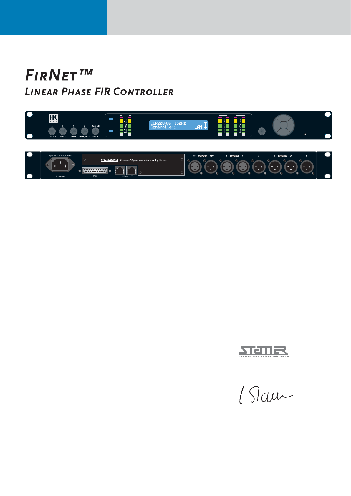
FIRNET Controller 1.1
FirNet™
Linear Phase FIR Controller
OutputsInputs
aes
sync
dB
BA
MuteLim LimOVL
dB
dB
BA
DC
Back Reset
Herzlichen
Glückwunsch!
Sie haben mit dem Kauf des HK AUDIO FIRNET
Linear Phase Controller eine hervorragende Wahl
getroffen.
Der HK AUDIO FIRNET Linear Phase Controller ist
das Ergebnis der über zehnjährigen Erfahrung mit
FIR-Filtertechnologie, gepaart mit der State of Art
Entwicklung bei AD/DA-Wandlern zur Steuerung
von digitalen Signalprozessoren. Ein durchdachtes
Bedienungskonzept hilft Ihnen bei der effi zienten
Verteilung und Bearbeitung ihrer Audiosignale, um
optimale Ergebnisse bei der Anwendung unserer
Lautsprechersysteme zu erzielen.
Nehmen Sie sich bitte ein wenig Zeit, um die
Inhalte dieser Bedienungsanleitung genau zu lesen,
damit Sie die bestmögliche Leistung mit diesem
Gerät erreichen können.
Dieses Benutzerhandbuch liefert eine detailliertere Beschreibung der Funktionen des FIRNET
Controllers. Für diejenigen unter Ihnen, die schon
Erfahrungen mit dieser Art von Controllern gemacht
haben, und die nur wissen müssen, wie mit dem
Bedienfeld zu „verfahren“ ist, steht auch eine
Kurzanleitung auf Seite 18 zur Verfügung.
Wichtige Sicherheitsinformationen
Bitte lesen Sie die folgenden Anweisungen und
Sicherheitsinformationen gründlich durch und
bewahren Sie sie auf. Beachten Sie alle Warnungen
und befolgen Sie die Anweisungen.
• Entfernen Sie nicht die Abdeckungen. Es gibt im
Inneren keine Teile, die vom Benutzer gewartet
werden können, überlassen Sie die Wartung bitte
qualifi ziertem Service-Personal.
• Dieses Gerät muss geerdet sein.
• Achten Sie darauf, dass niemand auf das Spannungsversorgungskabel tritt, und dass es nicht
gequetscht wird; besonders an den Steckern,
Steckdosen und an dem Punkt, wo es das Gerät
verlässt.
• Verwenden Sie nur vom Hersteller spezifi zierte/s
Zusatzgeräte/Zubehör.
• Wartungsarbeiten sind notwendig, wenn das Gerät
auf irgendeine Weise beschädigt wurde, wenn z. B.
das Stromversorgungskabel oder der Stecker beschädigt sind, Flüssigkeit in das Gerät geschüttet
wurde, Gegenstände in das Gerät gefallen sind,
wenn das Gerät Regen oder Nässe ausgesetzt war,
nicht normal funktioniert oder fallen gelassen
wurde.
Für das nachfolgend bezeichnete Erzeugnis
HK Audio FirNet™
wird hiermit bestätigt, dass es den wesentlichen Schutzanforderungen entspricht, die in der Richtlinie des
Rates zur Angleichung der Rechtsvorschriften der Mitgliedsstaaten über die elektromagnetische Verträglichkeit 2004/108/EG und der Niederspannungsrichtlinie
2006/95/EG festgelegt sind.
Diese Erklärung gilt für alle Exemplare und bestätigt
die Ergebnisse der Messungen, die durch die Qualitätssicherung der Fa. STAMER Musikanlagen GmbH
durchgeführt wurden. Zur Beurteilung des Erzeugnisses
hinsichtlich elektromagnetischer Verträglichkeit wurden folgende Normen herangezogen: EN61000-6-1,
EN61000-6-2.
Zur Beurteilung der Einhaltung der Niederspannungsrichtlinie wurde folgende Norm herangezogen: EN
60065
Diese Erklärung wird verantwortlich für den Hersteller
Magdeburger Str. 8, 66606 St. Wendel
abgegeben durch
Lothar Stamer Dipl.Ing.
Geschäftsführer
St. Wendel, den 08.08.2008
Version 2.0 08/2008
Page 17

Inhaltsverzeichnis:
1 Funktionsumfang .......................................................................................................................................... 18
2 Kurzanleitung ................................................................................................................................................ 18
Display, Menütasten, Channel Mute
3 Allgemeine Features ...................................................................................................................................... 18
3.1 FIR ..................................................................................................................................................................18
3.2 State of Art - Digitalwandler ............................................................................................................................18
3.3 Aufwändige Limiter ......................................................................................................................................... 18
3.4 Netzwerkfähig ................................................................................................................................................. 18
3.5 Losgelöst ........................................................................................................................................................18
3.6 GPIO/Option Slot - Vielfältig erweiterbar ....................................................................................................... 19
4 LIPAN PC-Software zur Fernsteuerung und Fernüberwachung ...................................................................... 19
4.1 Grundsätzliches ..............................................................................................................................................19
4.2 IP-Adresse ......................................................................................................................................................19
4.3 Datenbank für lautsprecherspezifi sche Filtersätze ..........................................................................................19
4.4 Volle Kontrolle ................................................................................................................................................ 19
4.5 Schneller Zugriff .............................................................................................................................................19
4.6 Controller in Gruppen ..................................................................................................................................... 19
4.7 Scene – Datenbank für veranstaltungsspezifi sche Einstellungen ....................................................................19
4.8 Stereo-Controller EQ .......................................................................................................................................19
17
5 Frontseite – Bedienung und Anzeigenfelder ..................................................................................................20
6 Rückseite – Anschlüsse ................................................................................................................................ 21
7 Menüfunktionen ........................................................................................................................................... 23
7.1 Übersicht der Menüfunktionen .......................................................................................................................23
7.2 Übersicht der Bedientasten ............................................................................................................................. 23
7.3 Startmenü – Darstellung der aktuellen Einstellungen .....................................................................................23
7.4 Einstellung der Parameter ...............................................................................................................................23
7.4.1 Speaker-Auswahl ............................................................................................................................................. 23
7.4.2 Scene – Laden und Speichern bereits abgespeicherter Einstellungen (Szenen) ..............................................24
7.4.3 Level – Pegeleinstellungen .............................................................................................................................24
7.4.4 Delay/Phase ....................................................................................................................................................24
7.4.5 Admin – Einstellung der übrigen Parameter ...................................................................................................25
7.4.5.1 Keylock – Tastensperre ................................................................................................................................... 25
7.4.5.2 Input Optionen ...............................................................................................................................................25
7.4.5.3 Utilities: Delay, Temperature, Display Contrast, Controller Name .................................................................. 26
7.4.5.4 Analog Levels ................................................................................................................................................. 26
7.4.5.5 Stummschalten von Ausgängen (Mute) ..........................................................................................................27
7.5 Firmware ........................................................................................................................................................27
8 Technische Daten ..........................................................................................................................................27
Deutsch
Page 18

FIRNET Controller 1.1
1 Funktionsumfang
Der FIRNET Controller realisiert auf digitaler Ebene
alle Funktionen, die zur Ansteuerung, Kontrolle und
Fernsteuerung von HK AUDIO Beschallungssystemen, d.h. Lautsprecher und Verstärker, notwendig
sind. Durch die Verwendung fortschrittlicher
AD- und DA-Wandlertechnologie und die interne
Abtastfrequenz von 96 kHz wird eine qualitativ
hochwertige Audiosignalverarbeitung erreicht.
2 Kurzanleitung
Display
Das LCD-Display zeigt Preset- und Parameterinformationen an. Nach dem Einschalten und während
des Boot-Vorgangs erscheint der Startbildschirm,
danach werden die aktuellen Einstellungen für
Speakerauswahl und LAN-Status angezeigt. Wenn
Sie die einstellbaren Parameter ansteuern, werden
entsprechend andere Informationen angezeigt.
Menütasten
Mit den Menütasten (Speaker, Level, Scene, Delay/
Phase und Admin) gelangen Sie in die einzelnen
Parametersektionen. Die dort angezeigten Parameter können Sie mit Hilfe der Edit-Select-Tasten
(Tastenkreuz und „Back“-Taste) für den ausgewählten Eingang und Ausgang verändern und abspeichern. Durch Drücken der Taste „back“ gelangen Sie
immer in die nächst höhere Menüebene.
Hinweis: Die gespeicherten Werte bleiben auch bei
einem eventuellen Stromausfall oder Entfernen des
Netzsteckers erhalten.
Channel-Mute
• Tastenkombination zum Muten der Output
Ausgänge A/B/C/D
Mit Hilfe einer Tastenkombination aus der Menütaste ADMIN und den vier anderen Menütasten
(Speaker, Scene, Level, Delay/Phase) lassen sich
die FIRNET Ausgangskanäle entsprechend ihrer
Reihenfolge A/B/C/D in Mute setzen. Beispiel:
zum Muten des Ausgangs A drücken Sie ADMIN
+ SPEAKER, für Ausgang D drücken Sie ADMIN +
DELAY/PHASE. Zum Entmuten wiederholen sie
einfach den entsprechenden Vorgang.
Hinweis: Die rote Signal-LED der Ausgangskanäle in
den Ausgängen zeigt den Mute-Status des jeweiligen Ausgangs an (permanent rot = MUTE).
3 Allgemeine Features
• FIR-Filter für Phasentreue und höchste
Natürlichkeit
• Wandlertechnologie der Spitzenklasse für einen
überragenden Dynamikumfang bis zu 130 dB
(A/D)
• aufwendiges Limiter-Design
• 96 kHz interne Sampling-Rate für höchste Aufl ösung und Transparenz
• Ethernet Anschlüsse zur Integration in ein
Netzwerk
• Ethersound und CobraNet usw. Interface (optional
nachrüstbar)
• GPIO-Schnittstelle
• LIPAN PC-Software zur Fernüberwachung
3.1 FIR
Die FIR-Filtertechnologie (Finite Impulse Response)
ermöglicht absolute Komponentenlinearität (Lautsprecher, Controller, Verstärker) im Phasenverlauf.
Das heißt, Betrag und Phase (bzw. Gruppenlaufzeit) der zu entzerrenden Beschallungssysteme
können unabhängig voneinander korrigiert werden.
Dadurch werden die unterschiedlichen Frequenzanteile eines Klangbildes zeitkohärent und damit
originalgetreu wiedergegeben. Durch Differenzen
im Phasengang verursachte Hörermüdung fi ndet
nicht mehr statt – Transparenz und Ortbarkeit
werden so deutlich erhöht.
FIR-Filter bestehen im Gegensatz zu IIR-Filtern
(Infi nite Impulse Response) nicht aus einer bestimmten Anzahl einzeln berechneter Filterelemente, sondern beinhalten das komplette gesampelte
Abbild der zur Entzerrung notwendigen Betragsund Phasenfunktion. Die FIR-Filter realisieren im
FIRNET Controller die Grundentzerrung für alle
Komponenten der HK AUDIO Beschallungssysteme
wie Lautsprecherchassis, Lautsprechergehäuse,
passive Frequenzweichen, Endstufen und den
Controller selbst.
Der Nachteil bisheriger FIR-Controller besteht
in einer hohen Latenz. Der FIRNET-Controller
ermöglicht die Nutzung der Vorteile von FIR-Filtern
bei minimaler Latenz, die bisher nur mit gewöhnlichen IIR-Controllern möglich war. Das bedeutet
unter anderem, dass nun der Einsatz der FIR-Technologie sogar für Monitor-Anwendungen genutzt
werden kann, wo sie für deutlich mehr „Gain before
Feedback“ sorgt.
Um die sehr geringe Latenz von maximal 5,8 ms
inklusive FIR-Filterung zu erhalten, werden zusätzlich optimierte IIR-Filtertypen eingesetzt.
3.2 State of Art - Digitalwandler
Um das Höchstmaß an Klangqualität und Dynamikwiedergabe erreichen zu können, verfügt der
FIRNET Controller über HighEnd-Digitalwandler
und Audio-DSPs, wie sie nur bei Studiogeräten der
Referenzklasse zum Einsatz kommen - mit einem
Dynamikumfang von bis zu 130 dB (A/D).
3.3 Aufwändige Limiter
Limiter müssen die Lautsprecher schützen und
sollten gleichzeitig die Lebendigkeit des Live-Klangbildes erhalten. Der FIRNET Controller verfügt
über Peak- und RMS-Limiter in allen Ausgängen.
Die Peak-Limiter ermitteln vorausschauend die an
den Verstärkerausgängen anliegende Leistung und
regeln diese bei drohender Überlastung auf für
die angesteuerten Lautsprechersysteme zulässige
Werte.
Die aufwändige Kombination aus vorausschauenden (2 ms) Peak-Limitern und RMS-Limitern mit
diskret justierten Threshold, Attack, Hold und Release-Zeiten gewährleisten einen sicheren Betrieb.
Hinweis: Für den korrekten Betrieb des FIRNET
an unterschiedlichen Endstufen sind folgende
Einstellungen erforderlich:
Einstellungen im Betrieb mit FP10000Q:
- Gain LAB: + 26 dBu
- Max D/A Level FIRNET (Admin view): + 18 dBu
Einstellungen im Betrieb mit VX 2400:
- Gain VX: + 35 dBu
- Max A/D Level FIRNET (Amin view): + 6 dBu
3.4 Netzwerkfähig
Der FIRNET Controller ist serienmäßig mit Ethernet-Anschlüssen (gekreuzter Signaleingang (X)
und paralleler Eingang ( II) auf der Rückseite des
Geräts) ausgestattet und ermöglicht über TCP/IP
die Einbindung in ein LAN-Netzwerk.
3.5 Losgelöst
Für den kabellosen Zugriff bei Live-Veranstaltungen
wird die Verbindung über einen Wireless Network
Access Point realisiert. Alle Einstellungsänderungen
können direkt von einem Laptop/Tablet-PC über ein
Wireless-Network an die Controller übertragen werden – von jedem Punkt aus dem Zuhörerraum aus.
Page 19

3.6 GPIO/Option Slot - Vielfältig
erweiterbar
Mit der GPIO-Schnittstelle steht eine universelle
Anschlussmöglichkeit zur Verfügung, die z.B als
Anbindung zu einer bestehenden Haus-Systemsteuerung genutzt werden kann. Der Option Slot
des FIRNET dient zur Aufnahme von in Zukunft
erhältlicher Erweiterungshardware wie CobraNet
Anschlüssen, Ethersound-Interface, digitale Multicoresysteme usw.) und trägt damit zur Investitionssicherheit des FIRNET bei.
4 LIPAN PC-Software zur Fernsteuerung
und Fernüberwachung
datenbank kann einfach per Mausklick reduziert
oder erweitert werden. Für ein übersichtlicheres
Arbeiten sind diese lautsprecherspezifi schen Filter
in der Datenbank nach den Lautsprecherserien von
HK AUDIO geordnet.
Alle Einstellungen können auf dem PC als Backup
gespeichert werden und bleiben so jederzeit
verfügbar.
4.4 Volle Kontrolle
Eine Darstellung aller angeschlossenen Controller
und benutzten Gruppen (Main window) erleichtert
4.1 Grundsätzliches
Die FIRNET Software LIPAN (WIN XP erforderlich)
ermöglicht die komplette Überwachung und Fernsteuerung eines einzelnen Controllers oder eines
Audio-Netzwerkes von bis zu 100 Geräten – und
das bei voller Übersicht. Das intuitive Bedienungskonzept lässt bereits bei der ersten Anwendung
wenig Fragen offen! Über die Standard-Ethernetanschlüsse auf der Rückseite des FIRNET ( Ethernet
X , II) können Sie Fernsteuer- und Überwachungsnetzwerke mit mehreren FIRNET Controllern
aufbauen. Einzelheiten zur Netzwerkverkabelung
entnehmen Sie bitte dem Kapitel 6.3 "Rückseite,
PC-Steuerungsanschlüsse Ethernet".
Mit einem im selben Netzwerk betriebenen PC und
der Fernsteuersoftware LIPAN sind Sie dann in der
Lage, alle am FIRNET eingestellten und angezeigten
Parameter vom PC aus abzufragen (Fernüberwachung), und alle am Controller möglichen Einstellungen auch vom PC aus vorzunehmen (Fernsteuerung). Darüber hinaus bietet die Software LIPAN
Ihnen weitere komfortable Funktionen wie die
gleichzeitige Steuerung mehrerer FIRNET Controller
mittels Gruppenbildung und des Gesamtsystems
mit einem zusätzlichen für jeden Controller voll
parametrischen IIR-EQ. Für weitere Informationen
lesen sie bitte im Handbuch zur Software LIPAN.
4.2 IP-Adresse
Jedes Gerät verfügt über eine voreingestellte und
über die Hardware editierbare IP-Adresse. Im
Netzwerk wird jeder Controller mit Namen (kann
frei vergeben werden) und eigener IP-Adresse
identifi ziert und kann individuell angesprochen
werden. Die Integration erfolgt in einem LAN oder
W-LAN-Netzwerkaufbau.
4.3 Datenbank für lautsprecherspezifische Filtersätze
Der FIRNET verfügt über eine erweiterbare Datenbank mit den Entzerrungsfunktionen für Betrag,
Phase und Belastbarkeit verschiedener Einzellautsprecher und Beschallungssysteme von HK AUDIO.
Im Controller können bis zu 100 spezifi sche
Lautsprecherfi lter abgespeichert werden. Die Filter-
die Übersicht des erstellten Netzerwerks. Jeder
Controller bzw. jede Gruppe kann in der Netzwerkübersicht mit einem Mausklick ausgewählt und
anschließend editiert werden.
4.5 Schneller Zugriff
Alle Funktionen des Controllers werden im „Controller window“ virtuell als „Channelstrip“ auf dem
Desktop abgebildet. Das Wechseln eines Lautsprecherfi lters, Ändern von Pegeln, Mute, Solo, Gruppenanzeige sowie Phasenumschaltung erfolgt mit
einem Mausklick in Echtzeit, ohne umständliches
Suchen oder das Wälzen von Bedienungsanleitungen. Im Administrator-Menü werden übersichtlich
alle Parameter wie IP-Adresse, Controller-Name,
Signal-Eingangsquelle, Einheiten für Temperatur,
Delay usw. angezeigt.
4.6 Controller in Gruppen
Mehrere Controller können in 16 verschiedenen
Gruppen zusammengefasst werden. Das vereinfacht die Veränderung gemeinsam zu bedienender
Parameter wie Pegelstrukturen oder Delay-Zeiten.
Alle Routings werden im Hauptfenster übersichtlich
dargestellt.
4.7 Scene - Datenbank für veranstaltungsspezifische
Einstellungen
Der FIRNET verfügt über eine Datenbank mit
zehn Speicherplätzen für veranstaltungsspezifi sche Einstellungen (Szenen). Damit werden bei
wiederkehrenden Veranstaltungen an wiederkehrenden Veranstaltungsorten die Setup-Zeiten des
Beschallungssystems reduziert und die Qualität der
Beschallung reproduzierbar.
4.8 Stereo-Controller EQ
Zur Entzerrung und Anpassung an die Räumlichkeiten bietet LIPAN für jeden Controller im Netzwerk
zusätzlich einen IIR-Stereo-EQ mit 4 vollparametrischen und 2 multifunktionalen Bändern
(Peak, Shelf, Cut). Mittels einer W-LAN-Verbindung
können so an verschiedenen Positionen im Zuhörerraum die Einstellungen überprüft und online sofort
in Echtzeit verändert werden.
19
Deutsch
Page 20

FIRNET Controller 1.1
5 Frontseite – Bedienung und Anzeigefelder
1 Taste SPEAKER
• Auswahl eines lautsprecherspezifi schen Filtersatzes aus einer ebenfalls auswählbaren Lautsprecherserie der FIRNET-internen Datenbank
2 Taste SCENE
• Aufrufen und Abspeichern von veranstaltungsspezifi schen FIRNET-Einstellungen aus bzw. in der
FIRNET-internen Datenbank.
3 Taste LEVEL
• Einstellung der Ein- und Ausgangspegel im
Bereich von -40 dB bis 12 dB
• Schrittweite = 0,1 dB im Bereich von 12 dB bis
-12 dB
• Schrittweite = 0,5 dB unterhalb von -12 dB
4 Taste DELAY/PHASE
• Einstellung von Delays bis 500 ms in den Eingängen des FIRNET Controllers
• Einstellung von Delays bis 25 ms in den Ausgängen des FIRNET
• Invertieren der Phasenlage des Audiosignals in
den Ein- und Ausgängen des FIRNET Controllers
5 Taste ADMIN
• Einrichten der Tastensperre zum Schutz gegen
unbefugte/unbeabsichtigte Bedienung
• Auswahl des Audiosignaleingangs und damit
zusammenhängender Optionen
• Einstellung der maximalen analogen Ein- und
Ausgangspegel zur Anpassung des FIRNET an
vor- bzw. nachgeschaltete Audiogeräte
• Einstellung von IP-Adresse, Controller-Name und
Displaykontrast
• Auswahl der Delay-Einheit (ms, m, ft, samples)
und der Umgebungstemperatur zur Ermittlung der
Schallgeschwindigkeit
6 LED-Anzeige AES IN
• leuchtet blau, wenn der digitale Signaleingang
AES/EBU IN im FIRNET Controller ausgewählt ist
• leuchtet nicht, wenn die analogen Signaleingänge
im FIRNET ausgewählt ist
7 LED-Anzeige EXT SYNC
• leuchtet blau, wenn im FIRNET die Synchronisation auf AES/EBU-Signal ausgewählt ist und Signal
anliegt.
• leuchtet nicht, wenn die interne Synchronisation
ausgewählt ist
8 LED-Anzeigen INPUTS (10 LEDs, grün/gelb/rot)
• grüner Bereich: Audio-Eingangspegel im Bereich
von -48 bis -12 dB unter Vollaussteuerung
• gelber Bereich: Audio-Eingangspegel im Bereich
von -12 bis 0 dB unter Vollaussteuerung
• roter Bereich: Audio-Eingangspegel übersteuert
den AD-Wandler
Hinweis: Ein Übersteuern des AD-Wandlers
verursacht Verzerrungen, auf die der Limiter des
FIRNET keinen Einfluss mehr nehmen kann. Wenn
die rote LED aufleuchtet, stellen Sie die Eingangsempfindlichkeit des FIRNET auf einen höheren Wert
(Abschnitt Einstellung des maximalen AD-Pegels im
Kapitel Einstellung der Parameter des FIRNET) oder
reduzieren Sie den Ausgangspegel des vorgeschalteten Audiogerätes! Achten sie hierbei auch auf
die empfohlenen Anpassungen an angeschlossene Verstärker, insbesondere beim Betrieb einer
FP10000Q-Endstufe.
9 LCD-Display
• 2 x 24 Zeichen
• zeigt im normalen Betriebszustand die Controllerbezeichnung, das ausgewählte Filter sowie das
Vorhandensein einer Netzwerkverbindung
• zeigt beim Aufruf von Menüs die jeweiligen Menüfunktionen sowie die editierbaren Parameter
10 LED-Anzeigen OUTPUTS
(10 LEDs, grün/gelb/rot)
• grüner Bereich: Audio-Ausgangspegel im Bereich
von -48 bis -12 dB unter Limiterwert
• gelber Bereich: Audio-Ausgangspegel im Bereich
von -12 bis 0 dB unter Limiterwert
• roter Bereich: Audio-Ausgangspegel wird durch
Limiterfunktion begrenzt oder der entsprechende
Ausgang ist stummgeschaltet (Mute, LED leuchtet
dauernd)
11 Back-Taste
• Rückkehr zur nächsthöheren Menüebene
• Verlassen von Editierfenstern ohne Übernahme
veränderter Einstellwerte
• Übernahme nicht mit Enter bestätigter Parameteränderungen
12 Navigations-Tastenkreuz
• Navigation zum jeweils nächsten oder vorherigen
Menupunkt
• Änderung der Parameter in den Editierfenstern
zum Auswählen und Ändern der Parameter
• obere Taste: Pfeil nach oben beim Scrollen in den
Menüs
• untere Taste: Pfeil nach unten beim Scrollen in
den Menüs
• rechte Taste zum Einstellen der Parameterwerte
(Zahlenwerte größer)
• linke Taste zum Einstellen der Parameterwerte
(Zahlenwerte kleiner)
• Enter-Taste zum Bestätigen des eingestellten
Wertes
13 Taste Reset
Der FIRNET Controller bootet nach 10 Sekunden
erneut. Anschließend werden die letzten Einstellungen geladen. Nicht gespeicherte Einstellungen
bleiben nicht erhalten.
14 Tastenkombinationen für Soft Reset und Hard
Reset
Der FIRNET verfügt über zwei weitere Reset-Funktionen:
Soft Reset: (Admin+Back+Enter für 3 Sekunden)
Laden des Default-Preset „Null“
Funktionen:
• kein Speaker/kein Filter ausgewählt
• kein Routing/kein Signal zu den Ausgängen
• alle FIR Ausgangskoeffi zienten auf 0
• keine Filter gesetzt, Filter muss neu geladen werden!
• X-Over auf bypass
• Input/Output-Gain auf 0
• Delay-Parameter auf 0
• IIR EQs alle Input Gains auf 0,
• IIR EQs Output auf Bypass (LIPAN Off) und Gain auf 0
• alle Limiter auf + 10dB Treshold
• Admin Parameter bleiben unverändert
• Outputs Mute 1-4, Ausgänge sind in Mute
Hard Reset: Auslieferungzustand ab Werk
(Speaker+Admin+Back für 3 Sekunden)
Funktionen:
• Filterbänke gelöscht
• Admin: Keylock not active
• Input assign A/B
• Input Source analog
• Sample Rate 96 kHz
• Dig Clk Sync: intern
• Delay unit: ms
• Temperature: 20°C
• Display Contrast: 15
• Name Device 0
• max Input: + 18 dBu
• max. Output + 6 dBu (Einstellung für VX 2400)
• IP wird nicht zurück gesetzt
Page 21

6 Rückseite – Anschlüsse
21
1 Netzanschluss 100-240 V~ / 50-60 Hz
Mit diesem dreipoligen Kaltgeräteanschluss mit
Schutzkontakt wird der Netzanschluss des FIRNET
Controllers hergestellt. Durch sein WeitbereichsNetzteil kann der Controller direkt ohne weitere
Maßnahmen (z.B. Umschalten) an allen Netzspannungen zwischen 100 V und 240 V betrieben
werden. Die maximale Leistungsaufnahme beträgt
40 VA. Das entspricht einer maximalen Stromaufnahme von ca. 175 mA bei einer Netzspannung
von 230 V bzw. Bei einer Netzspannung von 100
V beträgt die maximale Stromaufnahme ca. 400
mA. Für den Netzanschluss dürfen nur dreipolige
Anschlusskabel mit Schutzkontakt verwendet
werden. Die Netzsteckdose muss ebenfalls einen
Schutzkontakt besitzen. Bei Beschädigungen an
Kabeln oder Steckverbindern dürfen diese nicht
verwendet werden.
2 GPIO
Diese 25-polige Sub-D-Buchse führt jeweils vier potenzialfreie Ein- und Ausgänge, deren Funktion sich
mit späteren Firmware-Versionen ansprechen lässt
(z.B: Fernsteuerung von Endstufen, Umschalten
von angesteuerten Geräten). Dieses Feature wird in
der aktuellen Firmware noch nicht unterstützt.
Anschluss Ethernet X des ersten FIRNET Controller
mit dem Anschluss Ethernet II des zweiten FIRNET
Controller verbunden usw.
Tipp: Generell ist der Anschluss aller FIRNET
Controller an Switches zu empfehlen, da bei Direktverbindungen mehrerer FIRNET Controller beim
Ausfall eines Controllers die gesamte Netzwerklinie
nicht mehr funktioniert.
Abb: Netzwerkverbindung mit FIRNET und PC
Abb: Netzwerkverbindung mit Hub und PC
5 Digitaler Signalausgang AES/EBU OUT
Mit dieser dreipoligen XLR male Buchse kann das
am digitalen Signaleingang AES/EBU IN anliegende
Audiosignal digital an andere Geräte weitergeleitet
werden. Die Pinbelegung ist pin 1 = ground, pin 2
und 3 = Signal. Zur Erhaltung der Signalqualität
wird das digitale Audiosignal im FIRNET verstärkt.
Beim Ausfall eines FIRNET Controllers werden der
digitale Signaleingang AES/EBU IN und der digitale
Signalausgang AES/EBU OUT direkt parallel miteinander verbunden.
Zum Auswählen des digitalen Signaleingangs
gehen Sie ins Menü ADMIN (1x drücken), wählen
dann den Menüpunkt „Input Options“ (1x S und
mit ENTER bestätigen, dann 1x S und mit ENTER
bestätigen:
Menüpunkt - ADMIN/Input Options/ Input Source:
3 PC-Steuerungsanschlüsse Ethernet
Über die Ethernetanschlüsse werden Fernsteuerund Überwachungsdaten mittels aus der Computertechnik bekannter Netzwerkhardware zwischen
einem PC und den FIRNET Controllern übermittelt.
Die beiden Buchsen Ethernet X und Ethernet II sind
als RJ-45 Anschlussbuchse ausgeführt ( X = Input
für Cross Input, II = Parallel Input).
Verkabe lung:
Wird keine weitere Netzwerkhardware wie Hubs
und Switches verwendet, ist die Netzwerkbuchse
des PC mittels CAT5-Netzwerkkabel mit dem
Anschluss Ethernet X des ersten FIRNET Controller
zu verbinden. Der Anschluss Ethernet II des ersten
FIRNET Controller wird dann ebenfalls mittels
CAT5-Netzwerkkabel mit dem Anschluss Ethernet X
des zweiten FIRNET Controller verbunden usw.
Beim Anschluss des FIRNET Controller an Hubs
bzw. Switches wird der Anschluss Ethernet II des
FIRNET Controller mittels CAT5-Netzwerkkabel
mit einer Netzwerkbuchse des Hub bzw Switch
verbunden. Sollen weitere FIRNET Controller am
ersten Gerät angeschlossen werden, wird dann der
4 Digitaler Signaleingang AES/EBU IN
Mit dieser dreipoligen XLR female Buchse wird der
Anschluss an Signalquellen mit digitalem Ausgang
hergestellt. Die Pinbelegung ist pin 1 = ground, pin
2 und 3 = Signal. Der FIRNET Controller akzeptiert
(einstellbar über die Menüfunktion) Abtastfrequenzen von 48 kHz und 96 kHz.
Signalrouting Input-Output:
Der analoge Eingang INPUT A bzw. der linke Kanal
des digitalen AES/EBU-Signal liefert das Signal
für die Ausgänge OUTPUT A und OUTPUT B. Die
Ausgänge OUTPUT C und OUTPUT D erhalten ihr
Signal vom analogen Eingang INPUT B bzw. vom
rechten Kanal des digitalen AES/EBU-Signals.
Im Admin-Window der LIPAN-Software lässt sich
das Signalrouting verändern.
Synchronisationsverbindung bei analoger
Ansteuerung:
Werden mehrere FIRNET über die analogen Signaleingänge angesteuert, können die digitalen Signalein- und -ausgänge AES/EBU IN und AES/EBU
OUT zur Synchronisation der FIRNET Controller
untereinander genutzt werden. Dadurch bleibt die
Kohärenz des Audiosignals zwischen den FIRNET
Controllern gewährleistet.
Hierzu wird der digitale Signalausgang AES/
EBU OUT des ersten FIRNET mit dem digitalen
Signaleingang AES/EBU IN des zweiten FIRNET
Controller verbunden, der digitale Signalausgang
AES/EBU OUT des zweiten FIRNET Controller
mit dem digitalen Signaleingang AES/EBU IN des
dritten FIRNET Controller usw.
Deutsch
Page 22

FIRNET Controller 1.1
Der digitale Signaleingang AES/EBU IN des ersten
FIRNET und der digitale Signalausgang AES/EBU
OUT des letzten FIRNET Controller bleiben offen.
Da der erste FIRNET Controller den Synchronisationstakt für die anderen FIRNET Controller liefert,
wird bei ihm mittels Menufunktion die interne
Synchronisation ausgewählt. Die anderen Controller
werden entsprechend auf Synchronisation über
AES/EBU-Signal eingestellt. Als Eingang für das
Audiosignal werden bei allen FIRNET Controllern
mittels Menufunktion die analogen Signaleingänge
ausgewählt.
Hinweis: Durch das Aufleuchten der Sync-LED der
nachfolgenden Controller im Netzwerk, wird die
Synchronisation bestätigt.
6 Analoge Signaleingänge
Input A, Input B
Diese dreipoligen XLR female Buchsen werden zum
Anschluss an Signalquellen mit analogem Ausgang
verwendet. Die Pinbelegung ist pin 1 = ground,
pin 2 = Signal(+), pin 3 = Signal(-). Die Anschlüsse
sind elektronisch symmetriert, haben eine Eingangsimpedanz von 9 kOhm und werden durch ein elektronisches Filter vor HF-Einstreuungen geschützt.
Die Eingangsempfi ndlichkeit ist über eine Menüfunktion in vier Stufen auswählbar (6 dBu, 12 dBu,
18 dBu, 24 dBu), um den FIRNET Controller optimal
an den analogen Ausgang des vorgeschalteten
Audiogerätes anpassen zu können.
Dadurch kann ein stark verbesserter Rauschabstand
auf der analogen Eingangsseite des FIRNET Controllers erreicht werden.
Gehen Sie hierzu ins Menü ADMIN (1x drücken),
wählen dann den Menüpunkt Analog Levels (3x S)
und bestätigen mit ENTER.
Menüpunkt - ADMIN/Analog Levels:
Durch die Verwendung gestackter AD-Wandler beträgt die Eingangsdynamik des FIRNET >130 dB(A)
7 Analoge Signalausgänge Output A bis
Output D
Diese dreipoligen XLR-male-Buchsen führen die
Ausgangssignale zur Ansteuerung der Leistungsverstärker. Die Pinbelegung ist pin 1 = ground,
pin 2 = Signal(+), pin 3 = Signal(-). Die Anschlüsse
sind elektronisch symmetriert und haben eine Ausgangsimpedanz von 35 Ohm. Die Ausgangsdynamik
der DA-Wandler beträgt >124 dB(A).
Der maximale Ausgangspegel ist über eine Menüfunktion in vier Stufen auswählbar (6 dBu, 12 dBu,
18 dBu, 24 dBu), um den FIRNET Controller optimal
an den analogen Eingang des nachgeschalteten
Leistungsverstärkers anpassen zu können.
Hinweis: Bei der Anwendung des FIRNET Controllers in Verbindung mit LAB FP10000Q Leistungsverstärkern zur Ansteuerung von HK AUDIO
Lautsprechern muss die Einstellung des maximalen
Ausgangspegels (Max. Output) 18 dBu betragen.
Bei anderen Einstellungen besteht die Gefahr der
Zerstörung der angeschlossenen Lautsprecher, da
dann der Limiter des FIRNET nicht mehr wirkungsvoll begrenzt.
Damit die Limiter in Verbindung mit der LAB Gruppen Endstufe FP10000Q korrekt arbeiten, müssen
folgende Einstellungen der FP10000Q vorgenommen werden:
• Voltage Peak Limiter (VPL): 150 V im Soft-Mode
• Gain der FP10000Q: 26 dB
Einstellung des maximalen Ausgangspegels FIRNET: 18 dBu!
Hinweis: Nach einem Firmware-Update müssen
die Analog-Levels auf 18 dBu eingestellt werden
(s. Punkt 7: Analoge Signalausgänge).
Page 23

7. Menüfunktionen
23
7.1 Übersicht der Menüfunktionen
Mute Output A/B/C/D
Mit den Bedientasten-Kombination aus gehaltener
ADMIN- Taste (5) + Taste 1-4 für Output A bis D) lassen
sich die Ausgänge einzeln muten.
7.4 Einstellung der Parameter
Die Controllermenüs
Zum Bearbeiten der einzelnen Parameter stehen
fünf Menüpunkte zur Verfügung. Zur Auswahl der
Menüs drücken sie bitte die entsprechende Taste:
7.4.1 Speaker -Auswahl
Auswahl der Speaker Series und des entsprechenden Filters für den/die angeschlossenen Lautsprecher
7.2 Übersicht der Bedientasten
7.3 Startmenü - Darstellung der
aktuellen Einstellungen
Nach dem Einschalten (Stromanschluss hergestellt)
startet der Bootvorgang (Display zeigt TEST)
Dann erscheint im Display boottime mit wandernden < Zeichen. Am Ende des Bootvorgangs wird für
ca. 2 Sekunden die aktuelle Firmware angezeigt.
Danach werden im Startmenü des Controllers
folgende Parameter angezeigt:
• Preset No.
• Name des Controllers und LAN-Status
• aktuelle IP-Adresse
• aktuelle Scene
• aktuelles Routing
• Input Routing
• aktueller Input
• aktuelle Sample rate
• aktueller Synchronisationsstatus
• aktuelle Firmware-Version
Zur Auswahl eines lautsprecherspezifi schen Filtersatzes aus der Filterdatenbank des FIRNET drücken
Sie die Taste SPEAKER und wählen Sie anschließend
mit den Navigationstasten RS den Menüpunkt
Select Speaker Series, sofern dieser nicht bereits
ausgewählt ist. Drücken Sie die Taste ENTER, um
ins Untermenü Select Speaker Series zu gelangen
und wählen Sie dort mit der Navigationstaste S
eine Lautsprecherserie von HK AUDIO aus. Drücken
Sie die Taste ENTER, um eine ausgewählte Lautsprecherserie zu übernehmen.
Drücken Sie nun erneut die Taste SPEAKER und
wählen Sie anschließend mit den Navigationstasten
den Menüpunkt Select Filter (einmal S
RS
drücken). Drücken Sie die Taste ENTER, um ins
Untermenü Select Filter zu gelangen und wählen Sie
dort mit der Navigationstaste S einen lautsprecherspezifi schen Filtersatz für die zuvor ausgewählte Lautsprecherserie aus. Drücken Sie die Taste
ENTER, um einen ausgewählten lautsprecherspezifi schen Filtersatz in den FIRNET Controller zu laden.
Deutsch
Page 24

FIRNET Controller 1.1
7.4.2 Scene – Laden und Speichern
bereits abgespeicherter Einstellungen (Szenen)
Load Scene – Einlesen bereits abgespeicherter
Einstellungen (Szenen)
Zum Einlesen bereits erstellter und abgespeicherter
veranstaltungsspezifi scher FIRNET-Einstellungen
(Szenen) drücken Sie die Taste SCENE und wählen
sie anschließend mit den Navigationstasten RS
den Menüpunkt Load Scene, sofern dieser nicht bereits ausgewählt ist. Drücken Sie die Taste ENTER,
um ins Untermenü Load Scene zu gelangen und
wählen Sie dort mit den Navigationstasten QP
die Nummer einer gewünschten Szene von 0 bis 9
aus. Drücken Sie die Taste ENTER, um die gewählte
Szene in den FIRNET einzulesen. Wenn diese
andere lautsprecherspezifi sche Filtersätze als die
aktuelle Szene enthält, erscheint im LCD-Display
der Warnhinweis Different Speaker Series, den Sie
durch Drücken der Taste ENTER bestätigen müssen.
Danach erscheint im LCD-Display die Sicherheitsabfrage "Are you sure?", welche Sie ebenfalls durch
Drücken der Taste ENTER bestätigen müssen. Nach
dem erfolgreichen Einlesen der Szene erscheint im
LCD-Display die Meldung Scene X loaded.
Save Scene – Abspeichern der Einstellungen
als Szene
mit den Navigationstasten QP die Nummer eines
gewünschten Speicherplatzes von 0 bis 9 für die
Szene aus. Drücken Sie die Taste ENTER, um die
Szene auf dem gewählten Speicherplatz im FIRNET
abzuspeichern. Im LCD-Display erscheint die Sicherheitsabfrage "Are you sure?", welche Sie durch
Drücken der Taste ENTER bestätigen müssen. Nach
dem erfolgreichen Abspeichern der Szene erscheint
im LCD-Display die Meldung Scene X saved.
7.4.3 Level - Pegeleinstellungen
Einstellung der Eingangspegel
Hinweis: Der Eingangspegel bezieht sich auf die
Änderung der internen Signalbearbeitung (nach
dem A/D-Wandler), die sich auf die Ausgangspegel
auswirkt (Anzeige der Output levels vor dem D/AWandl er).
Zur Einstellung der Signalpegel an den Eingängen
des FIRNET drücken Sie die Taste LEVEL, und
wählen Sie anschließend mit den Navigationstasten
den Menüpunkt Input Level, sofern dieser
RS
nicht bereits ausgewählt ist. Nach Drücken der
Taste ENTER können Sie mit den Navigationstasten
einen Signaleingang (Input A oder Input B)
RS
auswählen und bei diesem mit den Navigationstasten Q P die gewünschte Pegelverstärkung einstellen. Drücken Sie danach die Taste ENTER, um die
eingestellte Pegelverstärkung zu übernehmen.
Einstellung der Ausgangspegel
bei diesem mit den Navigationstasten QP die
gewünschte Pegelverstärkung einstellen. Drücken
Sie danach die Taste ENTER, um die eingestellte
Pegelverstärkung zu übernehmen.
7.4.4 Delay/Phase
Einstellung des Eingangsdelays
Zur Einstellung des Delays an den Eingängen des
FIRNET drücken Sie die Taste DELAY/PHASE, und
wählen Sie anschließend mit den Navigationstasten
den Menüpunkt Delay (sofern dieser nicht be-
RS
reits ausgewählt ist). Drücken Sie die Taste ENTER
und wählen Sie nun mit den Navigationstasten
den Menüpunkt Input Delay (sofern dieser
RS
nicht bereits ausgewählt ist). Nach Drücken der
Taste ENTER können Sie mit den Navigationstasten
einen Signaleingang (Input A oder Input B)
RS
auswählen und bei diesem mit den Navigationstasten QP das gewünschte Delay im Bereich von
0 ms bis 500 ms einstellen. Drücken Sie danach
die Taste ENTER, um die Delay-Einstellung zu
übernehmen.
Einstellung des Ausgangsdelays
Wenn Sie alle veranstaltungsspezifi schen Einstellungen an einem FIRNET vorgenommen haben,
können Sie den Zustand des FIRNET als Szene
abspeichern. Dazu drücken Sie die Taste SCENE,
und wählen Sie mit den Navigationstasten RS
den Menüpunkt Save Scene (einmal S drücken).
Drücken Sie die Taste ENTER, um ins Untermenü
Save Scene No zu gelangen und wählen Sie dort
Zur Einstellung der Signalpegel an den Ausgängen
des FIRNET drücken Sie die Taste LEVEL, und
wählen Sie anschließend mit den Navigationstasten
den Menüpunkt Output Level (einmal S
RS
drücken). Nach Drücken der Taste ENTER können
Sie mit den Navigationstasten RS einen Signalausgang (Output A bis Output D) auswählen und
Zur Einstellung des Delays an den Ausgängen des
FIRNET drücken Sie die Taste DELAY/PHASE, und
wählen Sie anschließend mit den Navigationstasten
den Menüpunkt Delay (sofern dieser nicht
RS
bereits ausgewählt ist). Drücken Sie die Taste
ENTER und wählen Sie nun mit den Navigationstasten RS Menüpunkt Output Delay (einmal
drücken). Nach Drücken der Taste ENTER
S
können Sie mit den Navigationstasten RS einen
Signalausgang (Output A bis Output D) auswählen
und bei diesem mit den Navigationstasten QP
das gewünschte Delay im Bereich von 0 ms bis 25
ms einstellen. Drücken Sie danach die Taste ENTER,
um die Delay-Einstellung zu übernehmen.
Page 25

25
Einstellung der Phasenlage in den Eingängen
Der FIRNET bietet die Möglichkeit, in jedem
Signaleingang eine Phasenlage von 0° oder 180° für
das Audiosignal einzustellen. Dazu drücken Sie die
Taste DELAY/PHASE, und wählen mit den Navigationstasten RS den Menüpunkt Phase (einmal S
drücken). Drücken Sie die Taste ENTER und wählen
Sie nun mit den Navigationstasten RS den
Menüpunkt Input Phase (sofern dieser nicht bereits
ausgewählt ist). Nach Drücken der Taste ENTER
können Sie mit den Navigationstasten RS einen
Signaleingang (Input A oder Input B) auswählen
und bei diesem mit den Navigationstasten QP
die gewünschte Phasenlage von 0° oder 180° einstellen. Drücken Sie danach die Taste ENTER, um
die Einstellung der Phasenlage zu übernehmen.
Einstellung der Phasenlage in den Ausgängen
Der FIRNET Controller bietet ebenfalls die Möglichkeit, in jedem Signalausgang eine Phasenlage von
0° oder 180° für das Audiosignal einzustellen. Dazu
drücken Sie die Taste DELAY/PHASE, und wählen
mit den Navigationstasten RS den Menüpunkt
Phase (einmal S drücken). Drücken Sie die Taste
ENTER und wählen Sie nun mit den Navigationstasten RS den Menüpunkt Output Phase (einmal
drücken). Nach Drücken der Taste ENTER
S
können Sie mit den Navigationstasten RS einen
Signalausgang (Output A bis Output D) auswählen
und bei diesem mit den Navigationstasten QP
die gewünschte Phasenlage von 0° oder 180° einstellen. Drücken Sie danach die Taste ENTER, um
die Einstellung der Phasenlage zu übernehmen.
7.4.5. Admin - Einstellung der
übrigen Parameter
7.4.5.1 Keylock -Tastensperre zum
Schutz vor Zugriff gegen
unberechtigte Personen
Aktivierung der Tastensperre
Die Tastensperre sichert den FIRNET Controller vor
der (Fehl)Bedienung durch Unbefugte. Zur Aktivierung der Tastensperre rufen Sie durch Drücken
der Taste ADMIN das Admin-Menü auf. Wählen Sie
mit den Navigationstasten RS den Menüpunkt
Keylock (sofern dieser nicht bereits ausgewählt ist)
und drücken Sie die Taste ENTER. Im LCD-Display
erscheint die Abfrage Activate Keylock? zusammen
mit der Aufforderung zur Eingabe des Passwortes
(23). Wählen Sie mit dem Navigationstasten
die Zahl 23 aus und drücken Sie die Taste ENTER.
Die Aktivierung ist immer (am Gerät oder mit der
LIPAN-Software) durch Eingabe des Passworts
23 möglich. Merken oder notieren Sie sich das
Passwort. Ohne Passwort ist eine Deaktivierung der
Tastensperre nur mit angeschlossenem PC und der
Fernsteuersoftware LIPAN möglich.
Deaktivierung der Tastensperre
Zur Deaktivierung der Tastensperre rufen Sie durch
Drücken der Taste ADMIN das Admin-Menü auf. Da
der Menüpunkt Keylock bereits als einzig möglicher
ausgewählt ist drücken Sie zur Bestätigung nur
noch die Taste ENTER. Im LCD-Display erscheint
die Abfrage Deactivate Keylock? zusammen mit der
Aufforderung zur Eingabe eines Passwortes. Durch
Drücken der ENTER-Taste im Tasten-Navigationskreuz gelangen Sie zur Eingabe des Passworts.
Das Passwort ist fest vergeben und lautet 23.
Geben Sie das Passwort durch Drücken der
Taste ein und drücken Sie die Taste ENTER, um
die Tastensperre zu deaktivieren. Wird das falsche
Passwort ausgewählt, gelangen Sie erneut zum
Auswahlmenü der Keylock-Funktion.
QP
P
7.4.5.2 Input Optionen
Input Assign
• Auswahl zwischen getrenntem Signalinput für die
Eingänge A-B oder Input Link
Rufen Sie durch Drücken der Taste ADMIN das Admin-Menü auf. Wählen Sie mit Hilfe der Pfeiltasten
den Menüpunkt Input Options und bestätigen die
Auswahl mit ENTER. Wählen sie im Menüpunkt
Input Assign zwischen A/B und Link aus und bestätigen Sie die Auswahl mit Drücken der Taste ENTER.
Input Source
• Auswahl zwischen analogem und digitalem
Eingangssignal
Rufen Sie mit der Taste ADMIN das Admin-Menü
auf. Wählen Sie mit den Navigationstasten RS
den Menüpunkt Input Options (einmal S drücken)
und drücken Sie die Taste ENTER. Wählen Sie nun
mit den Navigationstasten RS den Untermenüpunkt Input Source (einmal S drücken) und stellen
Sie mit den Navigationstasten QP den analogen
(Analog) oder den digitalen (AES/EBU) Signaleingang ein. Drücken Sie anschließend die Taste
ENTER, um die Einstellung des Signaleingangs zu
übernehmen.
Sample Rate - Digital Clock Source
• Einstellung der Abtastfrequenz und des digitalen
AES/EBU-Eingangs
Die Ansteuerung des FIRNET über den digitalen
Signaleingang ist über zwei Abtastfrequenzen
(48 kHz / 96 kHz) des digitalen Audiosignals
möglich. Intern arbeitet der FIRNET immer mit
einer Abtastfrequenz von 96 kHz. Bei der Ansteuerung mit einem digitalen Audiosignal mit 48 kHz
Abtastfrequenz erfolgt im FIRNET eine Konvertierung der Abtastfrequenz des digitalen Audiosignals
auf 96 kHz.
Digital Clock Source
• Einstellung der Synchronisation bei analoger
Ansteuerung
Bei Ansteuerung des FIRNET über den analogen
Signaleingang kann zwischen zwei Betriebsarten
ausgewählt werden. Bei interner Synchronisation
synchronisiert sich der Controller auf eigenen Takt,
bei externer Synchronisation (FIRNET synchronisiert sich auf extern anliegenden Takt) auf den
AES/EBU-Eingang.
Wenn sich mehrere FIRNET Controller auf einen
extern anliegenden Takt synchronisieren, bleibt die
Kohärenz der Audiosignale zwischen den einzelnen
FIRNET Controller erhalten. Dies ist besonders
Deutsch
Page 26

FIRNET Controller 1.1
wichtig bei der Verwendung kohärent abstrahlender
Lautsprechereinheiten wie Linearrays.
Zur Einstellung der Synchronisation rufen Sie mit
der Taste ADMIN das Admin-Menü auf. Wählen Sie
mit den Navigationstasten RS den Menüpunkt
Input Options (einmal S drücken) und drücken Sie
die Taste ENTER.
Wählen Sie nun mit den Navigationstasten RS
den Untermenüpunkt Dig. CLK Sync (einmal R
drücken) und stellen Sie mit den Navigationstasten
die Synchronisation des FIRNET auf intern
QP
oder AES/EBU ein. Drücken Sie anschließend die
Taste ENTER, um die Einstellung der Synchronisation zu übernehmen. Die jeweilige Einstellung wird
am FIRNET Display angezeigt.
7.4.5.3 Utilities: Delay, Temperature,
Display Contrast, Controller
Name
Einstellung der Einheit für die Delay-Anzeige
Der FIRNET kann die Delay-Einstellungen in Millisekunden (ms), Metern (m), feet (ft) oder Samples
(SA) anzeigen. Zur Einstellung der Einheit für die
Delayanzeige rufen Sie mit der Taste ADMIN das
Admin-Menü auf. Wählen Sie mit den Navigationstasten RS den Menüpunkt Utilities (zweimal R
oder S drücken) und drücken Sie die Taste ENTER.
Wählen Sie nun mit den Navigationstasten RS
den Untermenüpunkt Delay Unit (sofern dieser
nicht bereits ausgewählt ist) und stellen Sie mit den
Navigationstasten QP die gewünschte Einheit für
die Delay-Anzeige ein. Drücken Sie anschließend
die Taste ENTER, um die eingestellte Einheit der
Delayanzeige zu übernehmen.
Der FIRNET berechnet die Delay-Anzeige bei den
Einheiten Meter (m) und feet (ft) aus dem Zeitwert
in Millisekunden (ms) mit Hilfe der temperaturabhängigen Schallgeschwindigkeit. Damit diese
Umrechnung korrekt erfolgen kann, muss die Umgebungstemperatur im FIRNET korrekt eingestellt
werden. Dazu rufen Sie mit der Taste ADMIN das
Admin-Menü auf. Wählen Sie mit den Navigationstasten RS den Menüpunkt Utilities (zweimal R
oder S drücken) und drücken Sie die Taste ENTER.
Wählen Sie nun mit den Navigationstasten RS
den Untermenüpunkt Temperature (einmal S
drücken) und stellen Sie mit den Navigationstasten
die aktuelle Umgebungstemperatur in °C ein.
QP
Drücken Sie anschließend die Taste ENTER, um die
eingestellte Umgebungstemperatur für die Umrechnung der Einheit der Delay-Anzeige zu übernehmen.
Einstellung des Kontrastes der LCD-Anzeige
Zur Anpassung des Kontrastes der LCD-Anzeige an
das Umgebungslicht rufen Sie mit der Taste ADMIN
das Admin-Menü auf. Wählen Sie anschließend
mit den Navigationstasten RS den Menüpunkt
Utilities (zweimal R oder S drücken) und drücken
Sie die Taste ENTER. Wählen Sie nun mit den Navigationstasten RS den Untermenüpunkt Display
Contrast (zweimal S drücken) und stellen Sie mit
den Navigationstasten QP den gewünschten
Kontrast des Displays im Bereich von 0 bis 31 ein.
Drücken Sie anschließend die Taste ENTER, um die
Kontrasteinstellung zu übernehmen.
Einstellung der Temperatur
Die Speicherung der Delay-Werte erfolgt im FIRNET
immer in Samples-ms. Über die Abtastfrequenz von
96 kHz kann das Delay dann in „ms“ umgerechnet
und angezeigt werden. Bei der Umrechnung in
„ms“ ist die Schallgeschwindigkeit von Relevanz .
Die widerum ist temperaturabhängig, so dass die
äußere Luftemperatur im FIRNET richtig eingestellt
sein muss.
Einstellung des Controller-Namen
Mit einem Controller-Namen (Beispiel: PA-left)
können Sie einen FIRNET logisch zu einem Lautsprecher bzw. einer Lautsprechergruppe zuordnen
und dadurch Ihr PA-Setup übersichtlicher gestalten.
Zur Änderung des Controller-Namens rufen Sie mit
der Taste ADMIN das Admin-Menü auf. Wählen Sie
anschließend mit den Navigationstasten RS den
Menüpunkt Utilities (zweimal R oder S drücken)
und drücken Sie die Taste ENTER. Wählen Sie nun
mit den Navigationstasten RS den Untermenüpunkt Contr. Name (zweimal R drücken). Nun
können Sie mit den Navigationstasten QP jeden
Buchstaben des angezeigten Controllernamens
ändern und dabei mit der Taste ENTER zum jeweils
nächsten Buchstaben des Controllernamens wechseln. Wenn Sie den gewünschten Controllernamen
eingestellt haben drücken Sie zur Übernahme die
Taste ENTER für ca. zwei Sekunden (bis rechts neben dem Controllernamen das Symbol < erscheint).
Änderung der IP-Adresse
Die IP-Adresse ist bei Auslieferung des FIRNET
werkseitig auf 192.168.1.100 eingestellt. Zur Änderung der IP-Adresse rufen Sie mit der Taste ADMIN
das Admin-Menü auf. Wählen Sie anschließend
mit den Navigationstasten RS den Menüpunkt
Utilities (zweimal R oder S drücken) und drücken
Sie die Taste ENTER. Wählen Sie nun mit den
Navigationstasten RS den Untermenüpunkt IP
Address (einmal R drücken). Nun können Sie mit
den Navigationstasten QP jede Ziffer der angezeigten IP-Adresse ändern und dabei mit der Taste
ENTER zur jeweils nächsten Ziffer der IP-Adresse
wechseln. Wenn Sie die gewünschte IP-Adresse
eingestellt haben, drücken Sie die Taste ENTER für
ca. zwei Sekunden (bis rechts neben der IP-Adresse das Symbol < erscheint). Zur Übernahme der
eingestellten IP-Adresse müssen Sie den FIRNET
zunächst vom Stromnetz trennen. Beim nächsten
Herstellen der Stromversorgung bootet der FIRNET
mit der geänderten IP-Adresse.
7.4.5.4 Analog Levels
Einstellung des maximalen Eingangspegels (AD)
Bei Ansteuerung des FIRNET über die analogen
Signaleingänge kann der Maximalpegel des ADWandlers (Eingangsempfi ndlichkeit) in vier Stufen
eingestellt werden (6 dBu, 12 dBu, 18 dBu, 24 dBu),
um den FIRNET optimal an das vorgeschaltete
Audiogerät anpassen zu können. Zur Einstellung
des Maximalpegels des AD-Wandlers (je kleiner
der Wert, desto höher die Eingangsempfi ndlichkeit
= höherer Eingangspegel) rufen Sie mit der Taste
ADMIN das Admin-Menü auf. Wählen Sie mit den
Navigationstasten RS den Menüpunkt Analog
Levels (einmal R drücken) und drücken Sie die
Taste ENTER. Wählen Sie nun mit den Navigationstasten RS den Untermenüpunkt Max. Input und
stellen Sie mit den Navigationstasten QP den
gewünschten Maximalpegel des AD-Wandlers ein..
Drücken Sie anschließend die Taste ENTER, um die
Einstellung des Maximalpegels des AD-Wandlers zu
übernehmen.
Hinweis: Beim Betrieb mit professionellen Mischpulten kann der Ausgangspegel bis zu +18 dBu (in
einigen Fällen auch +24 dBu )betragen. Der FIRNET
wird werksseitig auf +18 dBu eingestellt).
Der im Menü eingestellte, maximale Eingangspegelpegel des FIRNET sollte möglichst mit dem
maximalen Ausgangspegel des vorgeschalteten
Audiogerätes übereinstimmen.
Einstellung des maximalen Ausgangspegels (DA)
Mit der Einstellung des maximalen Ausgangspegels
(Max. Output) wird das analoge Ausgangssignal des
FIRNET an die nachgeschaltete Endstufe angepasst.
Wichtiger Hinweis: Für den korrekten und sicheren
Betrieb des FIRNET (Limitereinstellungen) an unterschiedlichen Leistungsverstärkern zur Ansteuerung
von HK AUDIO Lautsprechern ist auf folgende
Einstellungen der Max. Ausgangspegel zu achten:
Menü: Admin/Utilitites/Analog Levels/Max Output
Level
Einstellungen mit L.A.B. FP 10000 Q:
- Gain (L.A.B. FP 10000Q): + 26 dBu
Voltage Peak Limiter: 150V, Soft Mode
- Max Output (Firnet): + 18 dBu
Page 27

27
Einstellungen mit HK AUDIO, VX 2400:
- Gain VX 2400: + 35 dBu
- Max Output ( Firnet): + 6 dBu
Ein anderen Einstellungen besteht die Gefahr der
Zerstörung der angeschlossenen Lautsprecher, da
dann der Limiter des FIRNET nicht mehr
wirkungsvoll begrenzt.
7.4.5.5 Stummschalten von
Ausgängen (Mute)
Die Mute-Funktion ist beim FIRNET über eine
Zweitbelegung der Tasten SPEAKER, SCENE,
LEVEL, DELAY/PHASE und ADMIN realisiert. Die
für die Mute-Funktion zuständigen Tastenbezeichnungen fi nden Sie über der jeweiligen Taste. Zum
Stummschalten von Ausgängen drücken und halten
Sie die Taste Mute/Hold. Dazu drücken Sie dann
die Taste des Ausgangs, den Sie stummschalten
wollen (Tasten A bis D für Output A bis Output D).
Ist ein Ausgang stummgeschalten, leuchtet die LED
Lim/Mute in der LED-Kette des entsprechenden
Ausgangs rot. Zum Deaktivieren der Stummschaltung verwenden Sie denselben Ablauf.
7.5 Firmware
Die aktuelle Firmware des FIRNET Controllers ist
aufgespielt. Ein Update auf zukünftige FirmwareVersionen kann mit Hilfe der LIPAN Software
aufgespielt werden. Sehen sie hierzu bitte im
Kapitel Firmware update unter Kapitel 4 LIPAN
PC-Software nach
8 Technische Daten
Anschlüsse
Anschluss Eingang analog 3-pol. XLR female
Anschlussbelegung 1 = ground, 2 = Signal(+), 3 = Signal(-)
Eingangsimpedanz 9 kOhm
maximaler Eingangspegel schaltbar auf 6, 12, 18 oder 24 dBu
Eingangsdynamik >128 dB(A)
Anschluss Eingang digital 3-pol. XLR female
Anschlussbelegung 1 = ground, 2 = Signal, 3 = Signal
Eingangsimpedanz 110 Ohm
Protokoll AES 3 (AES/EBU)
Taktfrequenz 48 oder 96 kHz, intern 96 kHz
Synchronisation extern auf Datenquelle (Slave Mode)
Anschluss Ausgang digital 3-pol. XLR male
Anschlussbelegung 1 = ground, 2 = Signal, 3 = Signal
Ausgangsimpedanz 110 Ohm
Protokoll AES 3 (AES/EBU)
Signalaufbereitung Refresh von Signalform und -pegel (Bypass bei Stromausfall)
Anschluss Ausgänge analog 3-pol. XLR male
Anschlussbelegung 1 = ground, 2 = Signal(+), 3 = Signal(-)
Ausgangsimpedanz 35 Ohm
maximaler Ausgangspegel schaltbar auf 6, 12, 18 oder 24 dBu
Ausgangsdynamik > 125 dB(A)
Anschluss Netzspannung dreipoliger Kaltgeräteanschluss
Netzspannung / -frequenz 100 bis 240 V / 50 - 60 Hz
Leistungsaufnahme 40 VA
Max. Stromaufnahme bei 100 V: 400 mA
Max. Stromaufnahme bei 230 V: 175 mA
Anschluss Ethernet X RJ-45, gekreuzte Belegung
Anschluss Ethernet II RJ-45, direkte Belegung
Audiodaten (Linear Through Modus)
Frequenzgang (-1 dB) 5,5 Hz bis 34 KHz
THD+N (20 Hz bis 20 kHz) AD>DA Eingangspegel 21 dBu, R=100k, 96kHz 0,0012%-0,0013%
AES>DA Eingangspegel -3dBFS, R=100k, 96kHz 0,0010% - 0,0012%
Latenz (inkl. Limiter: AD > DA 96 KHz 3,15ms , AD > AES/EBU 96 KHz, AES/EBU > A 96 KHz
+ FIR Filter 5.8 ms
(Cohedra/Coh. Compact)
Digitale Signalverarbeitung
interne Abtastfrequenz 96 kHz
internes Datenformat 32 bit fl oating point
Aufl ösung AD-Wandler 28 Bit
Aufl ösung DA-Wandler 24 Bit
Betriebsbedingungen
Temperaturbereich -10° C bis +70°C
Mechanische Daten
Gewicht 3 kg • 6,6 lbs.
Abmessungen (B x H x T) 48 x 4,4 x 23,2 cm / 18-7/8 x 17-5/16 x 9-1/8"
Deutsch
Page 28

FIRNET Controller 1.1
FirNet™
Linear Phase FIR Controller
OutputsInputs
aes
sync
dB
BA
MuteLim LimOVL
dB
dB
BA
DC
Back Reset
Félicitations !
En achetant le contrôleur HK AUDIO FIRNET Linear
Phase Controller, vous avez fait le bon choix !
Le contrôleur HK AUDIO FIRNET Linear Phase Controller est le fruit de plus de dix ans d’expérience
en technologie de fi ltrage FIR et de l’évolution de
pointe de convertisseurs A/N et N-A permettant de
piloter des processeurs numériques de signal. De
plus, un concept de commande extrêmement bien
pensé vous aidera à répartir et traiter de manière
effi cace vos signaux audio et ce, afi n d’obtenir
des résultats optimaux dans l’utilisation de vos
systèmes de haut-parleurs.
Prenez donc quelques minutes pour lire attentivement le contenu de la présente notice d’utilisation
– c’est elle qui vous permettra de tirer la quintessence de cet appareil.
Ce manuel utilisateur fournit une description
détaillée des fonctions du contrôleur FIRNET.
Pour ceux d’entre vous qui ont déjà une certaine
expérience de ce type de contrôleur et qui ont donc
uniquement besoin de connaître ce qu’il est possible de faire via le panneau de commande, nous
fournissons également une notice brève, contenue
sur page 30.
Informations de sécurité
importantes
Veuillez lire attentivement les indications et
consignes de sécurité et conserver le présent
document. Respectez tous les avertissements et
conformez-vous aux indications fournies.
• Ne déposez pas les couvercles. En effet, l’intérieur
de l’appareil ne comprend aucune pièce qui puisse
être entretenue par l’utilisateur. Laissez donc
un personnel d’entretien qualifi é effectuer ces
opérations.
• Cet appareil doit être raccordé à la terre.
• Veillez à ce que personne ne marche sur le câble
d’alimentation secteur et à ce que celui-ci ne soit
écrasé en aucune manière, notamment au niveau
des prises murales, des connecteurs et du point
de sortie du câble sur l’appareil.
• Utilisez exclusivement des appareils supplémentaires/accessoires tels que ceux spécifi és par le
constructeur.
• Des travaux d’entretien sont nécessaires lorsque
l’appareil a été endommagé d’une manière
ou d’une autre, notamment lorsque le câble
d’alimentation secteur ou le connecteur ont été
endommagés, lorsque du liquide a été renversé
dans l’appareil, lorsque des objets sont tombés
dans l’appareil, lorsque celui-ci a été soumis à la
pluie ou à l’humidité, lorsqu’il ne fonctionne pas
normalement ou encore lorsqu’il a subi une chute.
This is to certify that
HK Audio FirNet™
complies with the provisions of the Directive of the
Council of the European Communities on the approximation of the laws of the Member States relating to
electromagnetic compatibility according to EMC directive 2004/108/EC and low voltage directive 2006/95/EC.
This declaration of conformity of the European Communities is the result of an examination carried out by
the Quality Assurance Department of STAMER GmbH
in accordance with European Standards EN61000-6-1,
EN61000-6-2, and EN 60065 for low voltage.
Magdeburger Str. 8, 66606 St. Wendel
Lothar Stamer Dipl.Ing.
Managing Director
St. Wendel, 08/08/2008
Version 2.0 08.08.08
Page 29

Sommaire:
1 Descriptif des fonctions ................................................................................................................................30
2 Notice brève .................................................................................................................................................. 30
Affi cheur, touches de menu, sourdine les sorties
3 Caractéristiques générales ............................................................................................................................30
3.1 Technologie FIR ..............................................................................................................................................30
3.2 Convertisseur numérique de pointe ................................................................................................................30
3.3 Limiteurs de qualité ........................................................................................................................................30
3.4 Compatibilité réseau .......................................................................................................................................30
3.5 Démarrage ...................................................................................................................................................... 31
3.6 Slot option/GPIO – possibilité d’extension multiple ....................................................................................... 31
4 Logiciel LIPAN PC pour commande à distance et surveillance à distance .......................................................31
4.1 Généralités ..................................................................................................................................................... 31
4.2 Adresse IP ....................................................................................................................................................... 31
4.3 Base de données pour jeux de fi ltres spécifi ques aux haut-parleurs ................................................................ 31
4.4 Contrôle total .................................................................................................................................................. 31
4.5 Accès rapide ................................................................................................................................................... 31
4.6 Contrôleurs en groupes .................................................................................................................................. 31
4.7 Scene – Base de données pour réglages spécifi ques aux représentations ....................................................... 31
4.8 EQ à contrôleur stéréo (Stereo EQ) ................................................................................................................ 31
29
5 Commande et champ d’affi chage .................................................................................................................. 32
6 Panneau arrière, connexions .........................................................................................................................33
7 Fonctions du menu ........................................................................................................................................35
7.1 Aperçu des fonctions du menu ....................................................................................................................... 35
7.2 Aperçu des touches de commande .................................................................................................................. 35
7.3 Menu Démarrage – Représentation des réglages actifs ................................................................................... 35
7.4 Spécifi cation des paramètres .......................................................................................................................... 35
7.4.1 Speaker – Sélection des haut-parleurs ............................................................................................................ 35
7.4.2 Scene – Chargement et mémorisation de réglages déjà enregistrés (scènes) .................................................36
7.4.3 Level – Réglages de niveaux ............................................................................................................................36
7.4.4 Delay/Phase ....................................................................................................................................................36
7.4.5 Admin – Réglage des autres paramètres ......................................................................................................... 37
7.4.5.1 Keylock – Verrouillage des touches pour protection contre accès par des personnes non autorisées .............. 37
7.4.5.2 Input, options .................................................................................................................................................37
7.4.5.3 Utilities : Delay, Temperature, Display Contrast, Controller Name ..................................................................38
7.4.5.4 Analog Levels ..................................................................................................................................................38
7.4.5.5 Mise en sourdine des sorties (Mute) ..............................................................................................................39
7.5 Firmware ........................................................................................................................................................39
8 Caractéristiques techniques ..........................................................................................................................39
Français
Page 30

FIRNET Controller 1.1
1 Descriptif des
fonctions
Le contrôleur FIRNET exécute, à un niveau numérique, toutes les fonctions qui sont nécessaires
à la commande, au contrôle et à la commande à
distance des systèmes de sonorisation HK AUDIO,
c’est-à-dire des haut-parleurs et amplifi cateurs.
Grâce à l’utilisation d’une technologie de pointe
de convertisseurs A/N et N/A et à une fréquence
d’échantillonnage interne de 96 kHz, on parvient à
un traitement de signal audio de très haute valeur
qualitative.
2 Notice brève
Afficheur
L’affi cheur à cristaux liquides (LCD) présente les
informations relatives aux présélections (Preset) et
aux paramètres. Après la mise sous tension et pendant le processus d’initialisation apparaît l’écran
de démarrage, puis viennent ensuite les réglages
en cours pour la sélection des haut-parleurs et
l’état du réseau local (LAN). Lorsque vous spécifi ez
les paramètres réglables, vous verrez également
apparaître d’autres informations.
Touches de menu
Les touches de menu (Speaker, Level, Scene, Delay/Phase et Admin) vous permettent d’entrer dans
les différentes sections relatives aux paramètres.
Les paramètres qui y sont indiqués peuvent être
modifi és et mémorisés via les touches Edit-Select
(pavé de touches et touche « Back ») pour l’entrée
et la sortie sélectionnées. Le fait d’appuyer sur la
touche « Back » vous permet de toujours revenir au
niveau de menu immédiatement supérieur.
Remarque : Les valeurs stockées restent conservées
même en cas de coupure de courant ou de retrait du
connecteur secteur.
Mise en sourdine des sorties (Mute)
• La combinaison de touches Channel et Mute
permet de mettre en sourdine les sorties Output
A/B/C/D
La combinaison de touches composée de la touche
menu Admin et des quatre autres touches menu
(Speaker, Scene, Level, Delay/Phase) vous permet
de placer en mode sourdine les canaux de sortie
FIRNET selon leur ordre A/B/C/D. Exemple : pour
mettre en sourdine la sortie A, appuyez sur Admin +
Speaker, pour la sortie D sur Admin + Delay/Phase.
Pour désactiver la sourdine, il vous suffi t de répéter
le processus.
Remarque : La DEL de signal rouge des canaux de
sortie dans les sorties indique l’état de sourdine
(MUTE) de la sortie correspondante (allumée rouge
en permanence = MUTE).
3 Caractéristiques générales
• Filtre FIR pour fi délité aux phases et caractère
naturel maximum
• Technologie de convertisseur d’avant-garde pour
un remarquable spectre dynamique pouvant
atteindre 130 dB (A/N)
• Design de limiteur remarquable
• Taux d’échantillonnage de 96 kHz pour une
résolution et une transparence maximales
• Connexions Ethernet pour intégration dans un
réseau
• Interfaces Ethersound, CobraNet, etc. (post équipements disponibles en option)
• Interface GPIO
• Logiciel LIPAN PC permettant une commande à
distance
3.1 Technologie FIR
La technologie de fi ltrage FIR (Finite Impulse
Response, réponse fi nie à une impulsion) permet
une linéarité absolue des composants (haut-parleurs, contrôleurs, amplifi cateurs) en déroulement
de phase. En d’autres termes, la valeur et la phase
(ou temps de propagation du groupe) des systèmes
de sonorisation à égaliser peuvent être corrigées
indépendamment l’une de l’autre. De cette façon,
les différentes parts de fréquence d’une image
sonore peuvent être cohérentes dans le temps et,
par conséquent, restituées avec toute la fi délité due
à l’original. Grâce à une différence dans les caractéristiques de pas de phase, la fatigue d’écoute ne
se produit plus – Transparence et localisation des
événements sonores sont ainsi considérablement
améliorés.
Contrairement aux fi ltres IIR (Infi nite Impulse
Response, réponse à impulsion infi nie), les fi ltres
FIR ne sont pas constitués d’un nombre déterminé
d’éléments de fi ltrage calculés individuellement,
mais contiennent la palette échantillonnée complète de la fonction de phase et de valeur requise pour
l’égalisation. Au sein du contrôleur FIRNET, les
fi ltres FIR réalisent l’égalisation de base pour tous
les composants des systèmes de sonorisation
HK AUDIO comme les racks de haut-parleurs,
les enceintes de haut-parleurs, les diviseurs de
fréquence passifs, les étages de puissance et le
contrôleur lui-même.
Jusqu’à présent, les contrôleurs FIR présentaient
l’inconvénient d’un temps de réponse élevé. Grâce
au contrôleur FIRNET, vous pourrez exploiter les
avantages des fi ltres FIR, mais avec un temps
de réponse minimum, tel qu’il était uniquement
disponible jusqu’à présent avec les contrôleurs IIR
habituels. Cela signifi e désormais, entre autres,
que la technologie FIR peut même être utilisée
dans les applications de monitoring où elle fournit
nettement plus de « Gain before Feedback ».
Pour obtenir un temps de réponse faible de
5,8 ms max avec le fi ltrage FIR, nous avons utilisé
des fi ltres IIR optimisés.
3.2 Convertisseur numérique de
pointe
Pour pouvoir atteindre un niveau maximum de qualité sonore et de restitution dynamique, le contrôleur FIRNET dispose de convertisseurs numériques
haut de gamme ainsi que de processeurs numériques de signal (DSP) audio qui sont normalement
uniquement disponibles sur des appareils de studio
de référence – et présentent un spectre dynamique
pouvant atteindre 130 dB (A/N).
3.3 Limiteurs de qualité
Les limiteurs ont pour fonction de protéger les
haut-parleurs. Ils doivent parallèlement préserver le
côté vivant de l’image sonore en live. Le contrôleur
FIRNET dispose de limiteurs Peak et RMS sur toutes les sorties. Les limiteurs de crête (peak) calculent à l’avance la puissance présente aux sorties de
l’amplifi cateur et régulent celle-ci en cas de menace
de surcharge par rapport aux valeurs admissibles
des systèmes de haut-parleurs pilotés.
L’association de haute qualité de deux limiteurs
de crête anticipatifs (2 ms) et de limiteurs RMS à
valeur de Threshold, Attack, Hold et Release prédéfi nis garantit un fonctionnement sûr.
Remarque : Les réglages suivants sont indispensables au bon fonctionnement du FIRNET sur divers
étages de sortie :
Réglage en association avec FP10000Q :
Gain LAB : + 26 dBu
Niveau N/A maxi du FIRNET (vue Admin.) :
+ 18 dBu
Réglage en association avec VX 2400 :
Gain VX : + 35 dBu
Niveau N/A maxi du FIRNET (vue Admin.) : + 6 dBu
3.4 Compatibilité réseau
Le contrôleur FIRNET est doté, de série, de connexions Ethernet (entrée de signal croisé (X) et entrée
parallèle (II) au dos de l’appareil) et permet, via le
protocole TCP/IP, l’intégration dans un réseau LAN.
3.5 Démarrage
Pour l’accès sans fi l lors de représentations live, la
connexion s’effectue via un Network Access Point,
point d’accès au réseau. Toutes les modifi cations
de réglages peuvent être directement transmises au
contrôleur au départ d’un ordinateur portable via
un réseau sans fi l et ce, depuis tout endroit de la
salle de concert.
Page 31

4 Logiciel LIPAN PC pour commande à distance et sur-
veillance à distance
31
3.6 Slot option/GPIO – possibilité d’extension multiple
Avec l’interface GPIO, vous disposez d’une possibilité de connexion universelle qui peut être utilisée
pour le raccordement à une commande système
domestique existante. L’Option Slot du FIRNET
permettra l’intégration des matériels d’extension
disponibles à l’avenir, telles les connexions CobraNet, l’interface Ethersound, les systèmes Multicore
numériques, etc. Elle contribue ainsi à la pérennité
de l’investissement que représente votre FIRNET.
4.1 Généralités
Le logiciel LIPAN (WIN XP indispensable) du
FIRNET permet la commande à distance et la
surveillance complètes d’un seul contrôleur ou d’un
réseau audio comprenant jusqu’à 100 appareils – et
ce, avec une vue d‘ensemble complète. Grâce au
concept de commande intuitif, vous trouverez des
réponses à toutes vos questions dès les premières
minutes d’utilisation ! Les connexions Ethernet
standard prévues au dos du FIRNET (Ethernet X
, II) vous permettent d’associer des réseaux de commande à distance et de surveillance avec plusieurs
contrôleurs FIRNET. Vous trouverez les détails
relatifs au câblage du réseau au chapitre 6.3 « Face
arrière, connexions de commande PC Ethernet ».
Avec un PC et le logiciel de commande LIPAN gérés
dans le même réseau, vous êtes en mesure de consulter, à partir du PC, tous les paramètres affi chés
et spécifi és (surveillance à distance), et de procéder,
aussi à partir du PC, à tous les réglages possibles
sur le contrôleur (commande à distance). En outre,
le logiciel LIPAN vous offre des fonctions conviviales comme la commande simultanée de plusieurs
contrôleurs FIRNET via la formation de groupes ou
le système complet avec un IIR-EQ entièrement paramétrique supplémentaire pour chaque contrôleur.
Pour toute information complémentaire, reportezvous au manuel du logiciel LIPAN.
4.2 Adresse IP
Chaque appareil dispose d’une adresse IP préréglée
et éditable via le hardware. Au sein du réseau, chaque
contrôleur est identifi é par un nom (librement
défi nissable) et une adresse IP propre et peut être
contacté individuellement. L’intégration s’effectue
dans une structure de réseau de type LAN ou W-LAN.
4.3 Base de données pour jeux de
filtres spécifiques aux hautparleurs
Le FIRNET dispose d’une base de données
extensible reprenant les fonctions de correction
pour la valeur, la phase et la capacité de charge de
différents haut-parleurs individuels et systèmes de
sonorisation HK AUDIO.
Le contrôleur peut stocker jusqu’à 100 fi ltres
spécifi ques aux haut-parleurs. La base de données
de fi ltres peut être réduite ou agrandie par
simple clic sur la souris. Pour pouvoir travailler de
façon ordonnée, les fi ltres spécifi ques aux haut-parleurs sont classés, au sein de la base de données,
selon les séries de haut-parleurs HK AUDIO.
Tous les réglages peuvent être stockés en copie de
sauvegarde sur le PC, ce qui leur permet donc de
rester à tout moment disponibles.
4.4 Contrôle total
Une représentation de tous les groupes utilisés
(Main Window) et contrôleurs raccordés facilite la
pleine perception du réseau créé. Chaque contrôleur ou chaque groupe peut ainsi être sélectionné
dans l’aperçu du réseau par un simple clic sur la
souris, puis édité.
4.5 Accès rapide
Toutes les fonctions du contrôleur sont illustrées
sur le bureau dans la fenêtre « Controller Window »
sous la forme de « Channelstrip ». Le changement
d’un fi ltre de haut-parleurs, la modifi cation des
niveaux, le mode Mute, le mode Solo, l’affi chage
des groupes ou encore la commutation des phases
s’effectuent en temps réel par un simple clic sur la
souris, sans recherches compliquées ou consultations fastidieuses de notices d’utilisation. Dans
le menu Administrateur fi gurent de façon claire
tous les paramètres comme l’adresse IP, le nom du
contrôleur, la source d’entrée du signal ou encore
les unités pour la température, le Delay, etc.
4.6 Contrôleurs en groupes
Plusieurs contrôleurs peuvent être rassemblés dans
16 groupes différents, ce qui simplifi e la modifi cation commune des paramètres à utiliser comme les
structures de niveau ou les temps de Delay. Tous les
routages sont représentés de façon claire dans la
fenêtre principale.
4.7 Scene - Base de données pour
réglages spécifiques aux
représentations
Le FIRNET dispose d’une base de données
comprenant dix emplacements mémoire pour les
réglages spécifi ques aux représentations (scènes).
De cette façon, le temps requis pour le réglage de la
balance du système de sonorisation dans le cas de
représentations multiples dans les mêmes salles se
voit réduit et la qualité de sonorisation peut donc
être reproduite.
4.8 EQ à contrôleur stéréo
Pour la correction et l’adaptation à la salle, LIPAN
propose en plus, pour chaque contrôleur du réseau,
un EQ IIR stéréo à 4 bandes entièrement paramétriques et 2 multifonction (Peak, Shelf, Cut). Via
une liaison W-LAN, vous pouvez ainsi vérifi er les
réglages en différents points de la salle et, le cas
échéant, les modifi er en ligne immédiatement, en
temps réel.
Français
Page 32

FIRNET Controller 1.1
5 Commande et champ d’affichage
1 Touche SPEAKER
• Sélection d’un jeu de fi ltres spécifi ques aux hautparleurs, dans une série de haut-parleurs également sélectionnables dans la base de données
interne du FIRNET.
2 Touche SCENE
• Appel et stockage de réglages FIRNET spécifi ques à la représentation, au départ de la base de
données interne du FIRNET.
3 Touche LEVEL
• Réglage des niveaux d’entrée et de sortie, sur une
plage allant de -60 dB à 12 dB.
• Incrément = 0,1 dB entre 12 dB et -12 dB
• Incrément = 0,5 dB sous les -12 dB
4 Touche DELAY/PHASE
• Réglage de Delays jusqu’à 500 ms dans les entrées
du contrôleur FIRNET.
• Réglage de Delays jusqu’à 25 ms dans les sorties
du FIRNET.
• Inversion de la position de phase du signal audio
dans les entrées et les sorties du contrôleur
FIRNET
5 Touche ADMIN
• Activation du verrouillage de touches pour protection contre utilisation accidentelle/non autorisée.
• Sélection de l’entrée du signal audio et par là
même, options connexes.
• Réglage du niveau d’entrée et de sortie analogique maximal pour adaptation du FIRNET à des
appareils audio branchés en amont ou en aval.
• Réglage de l’adresse IP, du nom du contrôleur et
du contraste d’affi chage.
• Sélection de l’unité de Delay (ms, m, ft,
échantillons) et de la température environnante
pour calcul de la vitesse du son.
6 Afficheur à DEL AES IN
• S’allume en bleu lorsque l’entrée numérique
de signal AES/EBU IN est sélectionnée dans le
contrôleur FIRNET.
• Ne s’allume pas lorsque les entrées analogiques
de signal sont sélectionnées dans le FIRNET.
7 Afficheur à DEL EXT SYNC
• S’allume en bleu lorsque, dans le FIRNET, la
synchronisation est sélectionnée sur le signal
AES/EBU et qu’un signal est présent.
• Ne s’allume pas lorsque la synchronisation interne
est sélectionnée dans le contrôleur.
8 Aff icheurs à DEL INPUTS
(10 DEL, vert/jaune/rouge)
• Zone verte : niveau d’entrée audio compris entre
-48 et -12 dB en réglage maximum.
• Zone jaune : niveau d’entrée audio compris entre
-12 et 0 dB.
• Zone rouge : le niveau d’entrée audio sature le
convertisseur A/N
Remarque : Une saturation du convertisseur A/N
provoque des distorsions sur lesquelles le limiteur
du FIRNET ne peut plus exercer aucune influence.
Lorsque la DEL rouge s’allume, vous devez régler la
sensibilité en entrée du FIRNET sur une valeur supérieure (paragraphe Réglage du niveau A/N maximal
dans le chapitre Réglage des paramètres du
FIRNET) ou réduire le niveau de sortie de l’appareil
audio connecté en amont ! Veillez ici à respecter les
adaptations recommandées sur les amplif icateurs
raccordés, notamment en cas de fonctionnement
d’un étage de puissance FP10000Q.
9 Afficheur à cristaux liquides (LCD)
• 2 x 24 caractères
• En état normal, indique la description du contrôleur, le fi ltre sélectionné ainsi que la présence
éventuelle d’une connexion réseau.
• En cas d’appel de menus, indique les fonctions
menu concernées ainsi que les paramètres
éditables.
10 Aff icheurs à DEL OUTPUTS
(10 DEL, vert/jaune/rouge)
• Zone verte : niveau de sortie audio entre -48 et
-12 dB sous valeur de limiteur
• Zone jaune : niveau de sortie audio entre -12 et
0 dB sous valeur de limiteur
• Zone rouge : le niveau de sortie audio est limité
par la fonction limiteur ou la sortie correspondante est mise en sourdine (Mute, la DEL reste
allumée en permanence)
11 Touche Back
• Retour au niveau de menu immédiatement
supérieur.
• Sortie des fenêtres d’édition sans prise en compte
des modifi cations des valeurs de réglage.
• Enregistrement de modifi cations de paramètres
non validées via Enter
12 Pavé de touches de navigation
• Navigation vers le point de menu précédent ou
suivant.
• Modifi cation des paramètres dans les fenêtres
d’édition, pour la sélection et la modifi cation des
paramètres.
• Touche supérieure : fl èche vers le haut pour
défi lement dans les menus.
• Touche inférieure : fl èche vers le bas pour
défi lement dans les menus.
• Touche de droite : réglage des valeurs de
paramètres (valeurs numériques superieurs).
• Touche de gauche : réglage des valeurs de
paramètres (valeurs numériques inférieures).
• Touche Enter pour validation de la valeur
sélectionnée.
13 Touche Reset
Le contrôleur FIRNET se relance après 10 secondes,
puis les derniers réglages sont chargés. À noter que
les réglages non sauvegardés en mémoire ne sont
pas conservés.
14 Combinaisons de touches pour Soft Reset (réini-
tialisation logicielle) et Hard Reset (réinitialisation matérielle)
Le FIRNET dispose de deux fonctions de réinitialisation supplémentaires :
Soft Reset: (Admin+Back+Enter pendant 3 sec.)
Chargement de la présélection par défaut « zéro »
Fonctions :
• Aucun haut-parleur/aucun fi ltre sélectionné
• Pas de routage, ni signal vers les sorties
• Tous coeffi cients de sortie FIR sur 0
• Pas de fi ltre spécifi é – le fi ltre doit être rechargé !
• X-Over sur Bypass
• Gain entrée/sortie sur 0
• Paramètres Delay sur 0
• IIR EQs – tous gains d’entrée sur 0,
• IIR EQs – sortie sur Bypass (LIPAN Off) et Gain sur 0
• Tous limiteurs sur niveau + 10dB
• Les paramètres d’administration restent inchangés
• Sourdine sorties 1-4, les sorties sont en sourdine
Hard Reset: état de livraison en sortie d’usine
(Speaker+Admin+Back pendant 3 secondes)
Fonctions :
• Banques de fi ltres effacées
• Admin : Keylock (verrouillage de touches) non activé
• Affectation d’entrée A/B
• Source d’entrée analogique
• Fréquence d’échantillonnage 96 kHz
• Synchronisation d’horloge numérique (Dig Clk Sync) :
interne
• Unité Delay : ms
• Température: 20°C
• Contraste de l’affi cheur : 15
• Nom appareil 0
• Entrée maxi : + 18 dBu
• Sortie maxi : + 6 dBu (réglage pour VX 2400)
• L’adresse IP n’est pas réinitialisée
Page 33

6 Panneau arrière, connexions
33
1 Connexion réseau 100-240 V~ / 50-60 Hz
La connexion réseau du contrôleur FIRNET est
réalisée au moyen d’une connexion tripolaire pour
appareils froids avec contact de protection. Grâce à
ce bloc d’alimentation à large spectre, le contrôleur
peut être branché sur toutes les sources de réseau
comprises entre 100 V et 240 V et ce, sans mesures
supplémentaires (p.ex. basculement). La puissance
absorbée maximale atteint 40 VA, ce qui correspond
à un courant absorbé maximum d’environ 175 mA,
pour une tension secteur de 230 V. En cas de tension secteur de 100 V, le courant absorbé maximal
est de 400 mA. La connexion au secteur requiert
obligatoirement et exclusivement des câbles de
raccordement tripolaires avec contact de protection.
La prise secteur murale doit également posséder un
contact de protection. Si les câbles ou connecteurs
sont endommagés, ne pas les utiliser.
2 GPIO
Cette douille Sub-D à 25 pôles concerne quatre
entrées et sorties hors potentiel dont la fonction
pourra être adaptée à des versions du Firmware
ultérieures (p.ex. : commande à distance des tâches
de puissance, commutation d’appareils pilotés).
Cette fonctionnalité n’est pas encore supportée par
le Firmware actuel.
FIRNET doivent être raccordés au premier appareil,
la connexion Ethernet X du premier contrôleur
FIRNET est reliée à la connexion Ethernet II du
deuxième contrôleur FIRNET et ainsi de suite.
Astuce : En général, nous recommandons de connecter tous les contrôleurs FIRNET à des switches
puisque, en cas de connexion directe de plusieurs
contrôleurs FIRNET, ce sera la ligne réseau complète qui ne fonctionnera plus si l’un des contrôleurs
vient à défaillir.
Illustration : Connexion réseau avec FIRNET et PC
Illustration : Connexion réseau avec hub et PC
5 Sortie numérique de signal AES/EBU OUT
Grâce à cette douille mâle XLR tripolaire, le signal
audio présent à l’entrée numérique de signal
AES/EBU IN peut être transféré de façon numérique
à d’autres appareils. L’affectation des broches est la
suivante : borne 1 = masse, bornes 2 et 3 = signal.
Pour obtenir la qualité du signal, le signal audio
numérique est amplifi é dans le FIRNET. En cas de
défaillance d’un contrôleur FIRNET, l’entrée numérique de signal AES/EBU IN et la sortie numérique
de signal AES/EBU OUT sont reliées l’une à l’autre
directement, en parallèle.
Pour la sélection de l’entrée numérique de signal,
passez au menu Admin (cliquez 1x), puis sélectionnez le point de menu « Input Options » (1x fl èche
vers le bas et validez via Enter), puis encore 1x
fl èche vers le bas et validez avec Enter :
Point de menu - ADMIN/Input Options/ Input
Source :
3 Raccords de commande PC Ethernet
Les connexions Ethernet permettent de calculer les
données de commande à distance et de surveillance
via un matériel réseau entre un PC et les contrôleurs FIRNET tels que ceux rencontrés en informatique. Les deux douilles Ethernet X et Ethernet II
sont exécutées en tant que douilles de connexion
RJ-45 (X = Input pour Cross Input,
II = Input parallèle).
Câblage :
Si aucun autre matériel de réseau comme des hubs
et des switches n’est utilisé, la douille de réseau
du PC doit être utilisée via le câble réseau CAT5
avec la connexion Ethernet X du premier contrôleur FIRNET. La connexion Ethernet II du premier
contrôleur FIRNET est dès lors également raccordée
à la connexion Ethernet X du deuxième contrôleur
FIRNET via un câble de réseau CAT5.
En cas de connexion du contrôleur FIRNET à des
hubs ou à des switches, la connexion Ethernet II
du contrôleur FIRNET est reliée par l’intermédiaire
d’un câble réseau CAT5 à une douille réseau du hub
ou du switch en question. Si d’autres contrôleurs
4 Entrée numérique de signal AES/EBU IN
Cette douille XLR femelle tripolaire sert à la connexion de sources de signal avec sortie numérique.
L’affectation des broches est la suivante : borne 1 =
masse, bornes 2 et 3 = signal. Le contrôleur FIRNET
accepte les fréquences d’échantillonnage de 48 kHz
et de 96 kHz (réglable via la fonction du menu).
Trajet de signal Input-Output
L’entrée analogique INPUT A ou le canal gauche du
signal numérique AES/EBU fournit le signal aux sorties OUTPUT A et OUTPUT B. Les sorties OUTPUT
C et OUTPUT D reçoivent, quant à elles, leur signal
de l’entrée analogique INPUT B ou du canal droit
du signal numérique AES/EBU.
Le routage du signal peut être modifi é dans la fenêtre Admin du logiciel LIPAN.
Connexion de synchronisation en cas de commande
analogique :
Si plusieurs FIRNET sont pilotés via les entrées
analogiques de signal, les entrées et sorties
numériques de signal AES/EBU IN et AES/EBU
OUT peuvent être utilisées pour la synchronisation
des contrôleurs FIRNET. De cette façon, on garantit
la cohérence du signal audio entre les contrôleurs
FIRNET.
Ici, la sortie numérique de signal AES/EBU OUT du
premier FIRNET est reliée à l’entrée numérique de
signal AES/EBU IN du deuxième contrôleur FIRNET.
De même, la sortie numérique de signal AES/EBU
OUT du deuxième contrôleur FIRNET est reliée à la
sortie du signal numérique AES/EBU IN du troisième contrôleur FIRNET Controller et ainsi de suite.
Français
Page 34

FIRNET Controller 1.1
La sortie numérique de signal AES/EBU IN du
premier FIRNET et la sortie numérique de signal
AES/EBU OUT du dernier contrôleur FIRNET
restent ouvertes. Étant donné que le premier contrôleur FIRNET fournit le rythme de synchronisation
pour les autres contrôleurs FIRNET, on sélectionne
pour lui la synchronisation interne via une fonction
du menu. Les autres contrôleurs s’alignent ainsi
sur la synchronisation via le signal AES/EBU. Pour
l’entrée du signal audio, les entrées analogiques de
signal sont sélectionnées via une fonction de menu
pour tous les contrôleurs FIRNET.
Remarque : La synchronisation est confirmée quand
la DEL Sync du contrôleur suivant dans le réseau
s’allume.
6 Entrées analogiques de signal INPUT A, INPUT B
Ces douilles XLR femelles tripolaires servent au
raccordement à des sources de signal à sortie
analogique. L’affectation des broches est la suivante
: borne 1 = masse ; borne 2 = signal(+) ; borne 3 =
signal(-). Les connexions sont équilibrées électroniquement, présentent une impédance d’entrée de
9 kohms et sont protégées contre les interférences
haute fréquence par un fi ltre électronique.
La sensibilité en entrée se règle sur quatre niveaux
(6 dBu, 12 dBu, 18 dBu, 24 dBu) via une fonction du
menu et ce, afi n de pouvoir adapter de façon optimale le contrôleur FIRNET à la sortie analogique de
l’appareil audio connecté en amont.
On obtient de cette façon un meilleur rapport signal/bruit du côté entrée analogique du contrôleur
FIRNET.
Pour ce faire, passez dans le menu Admin (cliquez
1x), puis sélectionnez le point de menu Analog
Levels (3x la fl èche vers le bas), puis validez avec
Enter.
Point de menu - ADMIN/Analog Levels :
7 Sorties analogiques de signal, OUTPUT A à
OUTPUT D
Ces douilles XLR mâles tripolaires véhiculent les
signaux de sortie servant à la commande des amplifi cateurs de puissance. L’affectation des broches est
la suivante : borne 1 = masse ; borne 2 = signal(+) ;
borne 3 = Signal(-) Les connexions sont équilibrées
électroniquement et présentent une impédance
de sortie de 35 ohms. La dynamique de sortie des
convertisseurs N/A atteint >124 dB(A). Le niveau de
sortie maximal se règle sur quatre niveaux (6 dBu,
12 dBu, 18 dBu, 24 dBu) via une fonction du menu,
de façon à pouvoir adapter de manière optimale
le contrôleur FIRNET à l’entrée analogique de
l’amplifi cateur de puissance branché en aval.
Remarque : En cas d’utilisation du contrôleur
FIRNET avec des amplificateurs de puissance LAB
FP10000Q pour le pilotage de systèmes de hautparleurs HK AUDIO, le réglage du niveau de sortie
maximal (Max. Output) doit atteindre 18 dBu. Si ce
réglage est différent, il y a risque de destruction des
haut-parleurs raccordés puisque le limiteur du FIRNET ne peut plus exercer sa fonction efficacement.
Pour que les limiteurs puissent travailler correctement en association avec l’étage de puissance des
groupes LAB FP10000Q, il convient de procéder
aux réglages suivants sur la FP10000Q :
• Tension au limiteur de crête (Voltage Peak Limiter,
VPL) : 150 V en mode Soft
• Gain de la FP10000Q : 26 dB
Réglage du niveau de sortie maximal du FIRNET :
18 dBu !
Grâce à l’utilisation de convertisseurs analogiques
numériques empilés, la dynamique d’entrée du
FIRNET atteint >130 dB(A).
Remarque : Après une mise à jour du Firmware, les
niveaux analogiques doivent être réglés sur 18 dBu
(voir point 7 : Sorties de signal analogiques)
Page 35

7. Fonctions du menu
35
7.1 Aperçu des fonctions du menu
Mute Output A/B/C/D
Ces touches de commande (association de la touche
Admin maintenue enfoncée et de la touche 1 à 4 pour
les sorties 1 à 4) permettent de mettre en sourdine
chacune des sorties.
7.4 Spécification des paramètres
Les menus du contrôleur
Cinq points de menu permettent de traiter les différents paramètres. Pour accéder aux menus, il suffi t
d’appuyer sur la touche correspondante :
7.4.1 Speaker – Sélection des hautparleurs
Sélection de la série de haut-parleurs et du fi ltre correspondant pour le(s) haut-parleur(s) raccordé(s).
7.2 Aperçu des touches de commande
7.3 Menu Démarrage – Représentation des réglages actifs
Après la mise sous tension (connexion secteur
réalisée), le processus d’initialisation commence
(l’affi cheur indique TEST). Apparaît ensuite dans
l’affi cheur le temps d’initialisation avec le signe <
variable. À la fi n du processus d’initialisation, la version du Firmware est affi chée pendant 2 secondes
environ. Le menu Démarrage du contrôleur affi che
ensuite les paramètres suivants
• numéro de Preset.
• nom du contrôleur et état du LAN
• adresse IP actuelle
• Scène actuelle
• Routage actuel
• Input routage
• Input actuel
• Fréquence d’échantillonnage active
• État de synchronisation actuel
• Firmware actuel
Pour sélectionner un jeu de fi ltres spécifi ques à
un haut-parleur dans la base de données de fi ltres
du FIRNET, appuyez sur la touche SPEAKER, puis
sélectionnez, via les touches de navigation RS, la
fonction Select Speaker Series (sélectionner la série
de haut-parleurs) pour autant que celle-ci ne soit
pas déjà sélectionnée. Appuyez ensuite sur la touche ENTER pour passer dans le sous-menu Select
Speaker Series, puis sélectionnez-y, via la touche
de navigation S une série de haut-parleurs
HK AUDIO. Appuyez ensuite sur la touche ENTER
pour valider la série de haut-parleurs sélectionnée.
Appuyez à nouveau sur la touche SPEAKER et
sélectionnez la fonction Select Filter (sélectionner
fi ltre) (appuyez une fois sur S via les touches de
navigation R et S. Appuyez ensuite sur la touche
ENTER pour parvenir dans le sous-menu Select
Filter et sélectionnez-y, via la touche de navigation
, un jeu de fi ltres spécifi ques aux haut-parleurs
S
Français
Page 36

FIRNET Controller 1.1
pour la série de haut-parleurs préalablement sélectionnée. Appuyez enfi n sur la touche ENTER pour
charger dans le contrôleur FIRNET le jeu de fi ltres
spécifi ques aux haut-parleurs sélectionné.
7.4.2 Scene – Chargement et
mémorisation de réglages déjà
mémorisés (scènes)
Load Scene – Récupération de réglages déjà mémorisés (scènes)
Pour récupérer des réglages FIRNET spécifi ques
à une représentation, déjà créés et enregistrés
(scènes), appuyez sur la touche SCENE, puis
sélectionnez la fonction Load Scene via les touches
de navigation RS pour autant que celle-ci ne soit
pas déjà sélectionnée. Appuyez sur la touche ENTER pour passer dans le sous-menu Load Scene et
sélectionnez-y, via les touches de navigation QP,
le numéro d’une scène souhaité compris entre 0 et
9. Appuyez ensuite sur la touche ENTER pour char-
ger la scène sélectionnée dans le FIRNET. Lorsque
celle-ci comprend d’autres jeux de fi ltres spécifi ques
à des haut-parleurs que ceux de la scène actuelle,
l’affi cheur à cristaux liquides émet le message
Different Speaker Series (série de haut-parleurs
différente) que vous devez valider en appuyant sur
la touche ENTER. Apparaît ensuite dans l’affi cheur
à cristaux liquides la question de sécurité Are you
sure? que vous devez également confi rmer par la
touche ENTER. Après la récupération réussie de la
scène, apparaît le message Scene X loaded (scène
untel chargée) dans l’affi cheur à cristaux liquides.
sous Scène. Pour ce faire, cliquez sur la touche
SCENE et sélectionnez, via les touches de navigation RS la fonction Save Scene (appuyez une fois
sur S). Appuyez ensuite sur la touche ENTER pour
passer au sous-menu Save Scene No (sauvegarder
n° de scène) et sélectionnez-y, via les touches
de navigation QP, le numéro d’emplacement
mémoire de votre choix (de 0 à 9) pour la scène
en question. Appuyez ensuite sur la touche ENTER
pour sauvegarder la scène sur l’emplacement
mémoire sélectionné dans le FIRNET. Apparaît
alors sur l’affi cheur à cristaux liquides la question
de sécurité Are you sure? que vous validerez en
appuyant de nouveau sur la touche ENTER. Après
la sauvegarde réussie de la Scène apparaît dans
l’affi cheur à cristaux liquides le message Scene X
saved (scène untel sauvegardée).
7.4.3 Level – Réglages des niveaux
Réglage des niveaux d’entrée
Pour régler les niveaux d’entrée aux entrées
du FIRNET, appuyez sur la touche LEVEL, puis
sélectionnez, via les touches de navigation RS,
la fonction Input Level, sauf si celle-ci est déjà
sélectionnée. Après pression sur la touche ENTER,
vous pouvez, via les touches de navigation RS,
sélectionner une entrée de signal (Input A ou Input
B), puis lui affecter, via les touches de navigation
, l’amplifi cation de niveau que vous désirez.
QP
Appuyez enfi n sur la touche ENTER pour valider
l’amplifi cation de niveau sélectionnée.
Réglage des niveaux de sortie
D), puis lui affecter, via les touches de navigation
, l’amplifi cation de niveau que vous désirez.
QP
Appuyez enfi n sur la touche ENTER pour valider
l’amplifi cation de niveau sélectionnée.
7.4.4 Delay/Phase
Réglage du Delay d’entrée
Pour régler le Delay aux entrées du FIRNET, appuyez sur la touche DELAY/PHASE, puis sélectionnez, via les touches de navigation RS, la fonction
Delay, pour autant que celle-ci ne soit pas déjà
sélectionnée. Appuyez ensuite sur la touche ENTER,
puis sélectionnez, via les touches de navigation
, la fonction Input Delay, pour autant que cel-
RS
le-ci ne soit pas déjà sélectionnée. Après pression
sur la touche ENTER, vous pouvez, via les touches
de navigation RS, sélectionner une entrée de
signal (Input A ou Input B) et puis, via les touches
de navigation QP, régler le Delay souhaité sur
une plage comprise entre 0 ms et 500 ms. Appuyez
enfi n sur la touche ENTER pour valider le réglage
du Delay.
Réglage du Delay de sortie
Save Scene – Mémorisation des réglages de scène
À partir du moment où vous avez procédé à tous les
réglages spécifi ques à une représentation dans un
FIRNET, vous pouvez sauvegarder ce paramétrage
Pour régler les niveaux de sortie aux sorties
du FIRNET, appuyez sur la touche LEVEL, puis
sélectionnez, via les touches de navigation RS, la
fonction Output Level (appuyez une fois sur la touche S). Après pression sur la touche ENTER, vous
pouvez sélectionner, via les touches de navigation
, une sortie de signal (de Output A à Output
RS
Pour régler le Delay aux sorties du FIRNET, appuyez
sur la touche DELAY/PHASE, puis sélectionnez, via
les touches de navigation RS, la fonction Delay,
pour autant que celle-ci ne soit pas déjà sélectionnée. Appuyez ensuite sur la touche ENTER, puis
sélectionnez, via les touches de navigation RS,
la fonction Output Delay (appuyez une fois sur S).
Après pression sur la touche ENTER, vous pouvez,
via les touches de navigation RS, sélectionner
une sortie de signal (de Input A à Input D) et puis,
via les touches de navigation QP, régler le Delay
souhaité sur une plage de 0 ms à 25 ms. Appuyez
enfi n sur la touche ENTER pour valider le réglage
du Delay.
Page 37

37
Réglage de la position de phase dans les entrées
Le FIRNET offre la possibilité, pour chaque entrée
de signal, de régler une position de phase de 0° ou
180° pour le signal audio. Pour ce faire, appuyez
sur la touche DELAY/PHASE, puis sélectionnez,
via les touches de navigation RS, la fonction
Phase (appuyez une fois sur la touche S). Appuyez
ensuite sur la touche ENTER, puis sélectionnez, via
les touches de navigation RS, la fonction Input
Phase pour autant que celle-ci ne soit pas déjà
sélectionnée. Après pression sur la touche ENTER,
vous pouvez, via les touches de navigation RS,
sélectionner une entrée de signal (Input A ou Input
B) et puis, via les touches de navigation QP,
spécifi er la position de phase souhaitée, soit 0°
ou 180°. Appuyez enfi n sur la touche ENTER pour
valider le réglage de la position de phase.
Réglage de la position de phase dans les sorties
Le contrôleur FIRNET offre également la possibilité,
pour chaque sortie de signal, de spécifi er une position de phase de 0° ou 180° pour le signal audio.
Pour ce faire, appuyez sur la touche DELAY/PHASE,
puis sélectionnez, via les touches de navigation
, la fonction Phase (appuyez une fois sur la
RS
touche S). Appuyez ensuite sur la touche ENTER,
puis sélectionnez, via les touches de navigation
, la fonction Output Phase (appuyez une fois
RS
sur la touche S). Après pression sur la touche
ENTER, vous pouvez, via les touches de navigation
, sélectionner une sortie de signal (de Output
RS
A à Output D) et puis, via les touches de navigation
, spécifi er la position de phase souhaitée, soit
QP
0° ou 180°. Appuyez enfi n sur la touche ENTER pour
valider le réglage de la position de phase.
7.4.5. Admin – Réglage des autres
paramètres
7.4.5.1 Keylock – Verrouillage des
touches pour protection
contre accès par des personnes non autorisées
Activation du verrouillage des touches
Le verrouillage de touches protège le contrôleur
FIRNET contre toute fausse manœuvre ou utilisation par des personnes non autorisées. Pour activer
le verrouillage de touches, appelez d’abord le menu
Admin en appuyant sur la touche ADMIN, puis
sélectionnez la fonction Keylock via les touches de
navigation RS (pour autant que celle-ci ne soit
pas déjà activée) et enfi n, validez via la touche ENTER. Sur l’affi cheur à cristaux liquides apparaît alors
la question Activate Keylock? ainsi qu’une invitation
à saisir le mot de passe (23). Choisissez le chiffre 23
via les touches de navigation QP, puis appuyez
sur la touche ENTER.
L’activation est toujours possible par saisie du
mot de passe 23 (sur l’appareil ou grâce au logiciel
LIPAN). Veillez à repérer ou noter le mot de passe.
Sans mot de passe, la désactivation du verrouillage
des touches est uniquement possible, PC fermé, via
le logiciel de commande à distance LIPAN.
Désactivation du verrouillage des touches
Pour désactiver le verrouillage de touches, appelez
le menu Admin en appuyant sur la touche ADMIN.
Étant donné que la fonction Keylock est déjà
sélectionnée (car elle est la seule possible), il vous
suffi t d’appuyer sur la touche ENTER pour valider
le choix. Sur l’affi cheur à cristaux liquides apparaît
alors la question Deactivate Keylock? ainsi que
l’invite à saisir un mot de passe. Appuyez sur la touche ENTER sur la croix de navigation pour passer à
la saisie du mot de passe.
Le mot de passe, 23, est déterminé une fois pour
toutes.
Entrez le mot de passe en appuyant sur la touche
, puis sur la touche ENTER, pour désactiver le
P
verrouillage de touches. Si le mot de passe est
erroné, vous devrez revenir au menu de sélection
dans la fonction Keylock.
7.4.5.2 Input, options
Input Assign
• Sélection entre l’entrée de signal séparée pour les
entrées A-B ou Input Link
Appuyez sur la touche ADMIN du menu Admin
pour l’appeler. À l’aide des touches de fl èche, sélectionnez la fonction Input Options, puis confi rmez
la sélection via la touche ENTER. Dans la fonction
Input Assign, sélectionnez A/B et Link, puis validez
la sélection via la touche ENTER.
Input Source
• Sélection entre signal d’entrée analogique et
numérique
Appuyez sur la touche ADMIN du menu Admin
pour l’appeler. Via les touches de navigation RS,
sélectionnez la fonction Input Options (appuyez
une fois sur la touche S), puis validez via la touche
ENTER. Sélectionnez à présent, via les touches de
navigation RS, l’option Input Source (appuyez
une fois sur S), puis spécifi ez, via les touches de
navigation QP l’entrée de signal analogique (Analog) ou l’entrée de signal numérique (AES/EBU).
Appuyez enfi n sur la touche ENTER pour valider le
réglage de l’entrée de signal.
Fréquence d’échantillonnage – Source d’horloge
numérique
• Réglage de la fréquence d’échantillonnage et de
l’entrée numérique AES/EBU
La commande du FIRNET par l’entrée de signal
numérique est possible via deux fréquences
d’échantillonnage (48 kHz / 96 kHz) du signal
audio numérique. En interne, le FIRNET travaille
toujours avec une fréquence d’échantillonnage de
96 kHz. Si la commande s’effectue avec un signal
audio à fréquence d’échantillonnage de 48 kHz, le
FIRNET procède à une conversion à 96 kHz de la
fréquence d’échantillonnage du signal audio.
Digital Clock Source
• Réglage de la synchronisation en cas de commande analogique
Si le FIRNET est commandé par l’entrée de signal
analogique, vous avez le choix entre deux modes
de fonctionnement. En cas de synchronisation
interne, le contrôleur se synchronise sur sa propre
fréquence, tandis qu’en cas de synchronisation
externe (le FIRNET se synchronise sur une fréquence d’origine externe), il adopte celle de l’entrée
AES/EBU.
Si plusieurs contrôleurs FIRNET se synchronisent
sur une fréquence d’origine externe, la cohérence
Français
Page 38

FIRNET Controller 1.1
des signaux audio entre les divers contrôleurs FIRNET est préservée. C’est un aspect particulièrement
important lors de l’utilisation d’unités de haut-parleurs à diffusion cohérente comme les Linearrays.
Pour procéder au réglage de la synchronisation,
appelez le menu Admin via la touche ADMIN.
Sélectionnez alors, via les touches de navigation
, la fonction Input Options (appuyez une fois
RS
sur S), puis appuyez sur la touche ENTER.
Sélectionnez à présent, via les touches de navigation RS, l’option Dig. Clk Sync (appuyez une fois
sur R), puis, via les touches de navigation QP,
réglez la synchronisation du FIRNET sur Intern ou
AES/EBU. Appuyez enfi n sur la touche ENTER pour
valider le réglage de la synchronisation. Le réglage
spécifi é apparaît alors sur l’affi cheur du FIRNET.
7.4.5.3 Utilities: Delay, Temperature,
Display Contrast, Controller
Name
Réglage de l’unité d’affichage du Delay
Le FIRNET peut affi cher son Delay en millisecondes
(ms), en mètres (m), en feet (ft) ou en Samples
(échantillons) (SA). Pour régler l’unité d’affi chage
du Delay, appelez le menu Admin via la touche
ADMIN. Sélectionnez, via les touches de navigation
, la fonction Utilities (appuyez deux fois sur
RS
), puis appuyez sur la touche ENTER. Sélec-
RS
tionnez à présent, via les touches de navigation
, l’option Delay Unit pour autant que celle-ci
RS
ne soit pas déjà sélectionnée, puis spécifi ez, via les
touches de navigation QP, l’unité désirée pour
l’affi chage du Delay. Appuyez enfi n sur la touche
ENTER pour valider l’unité sélectionnée pour
l’affi chage du Delay.
Le FIRNET calcule l’affi chage du Delay pour les
unités mètre (m) et feet (pied) (ft) à partir de la
valeur temporelle en millisecondes (ms) et ce,
avec l’aide de la vitesse du son dépendant de la
température. Pour que cette conversion puisse être
effectuée correctement, la température ambiante
doit être correctement spécifi ée dans le FIRNET.
Pour ce faire, appelez le menu Admin via la touche
ADMIN. Sélectionnez, via les touches de navigation
, la fonction Utilities (appuyez deux fois sur
RS
ou S), puis appuyez sur la touche ENTER. Sé-
R
lectionnez à présent, via les touches de navigation
, l’option Temperature (appuyez une fois sur
RS
), puis spécifi ez, via les touches de navigation
S
, la température ambiante ponctuelle en °C.
QP
Appuyez ensuite sur la touche ENTER pour valider
la température ambiante réglée pour le calcul de
l’unité d’affi chage du Delay.
Réglage du contraste de l’afficheur à cristaux
liquides (LCD)
Pour adapter le contraste de l’affi cheur à cristaux
liquides à la luminosité ambiante, appelez le menu
Admin via la touche ADMIN. Sélectionnez ensuite,
via les touches de navigation RS, la fonction
Utilities (appuyez deux fois sur R ou sur S), puis
appuyez sur la touche ENTER. Sélectionnez à présent, via les touches de navigation RS, l’option
Display Contrast (appuyez deux fois sur S), puis
réglez, via les touches de navigation QP, le contraste souhaité pour l’affi cheur et ce, sur une plage
allant de 0 à 31. Appuyez enfi n sur la touche ENTER
pour valider le réglage du contraste.
Spécification de la température
Dans le FIRNET, la mise en mémoire des valeurs
de DELAY s’effectue toujours en Samples-ms. Via
la fréquence d’échantillonnage de 96 kHz, le Delay
peut alors être converti en « ms », puis affi ché. La
vitesse du son revêt une grande importance dans le
processus de conversion en « ms ». Comme celle-ci
est dépendante de la température, la température
de l’air extérieur doit absolument être correctement
spécifi ée dans le FIRNET.
Spécification du nom du contrôleur
Grâce au nom donné au contrôleur (par exemple,
PA gauche), vous pourrez logiquement affecter un
contrôleur FIRNET à un groupe de haut-parleurs
et ainsi constituer de façon claire la confi guration
de votre PA. Pour modifi er le nom du contrôleur,
appelez le menu Admin via la touche ADMIN.
Sélectionnez, via les touches de navigation RS,
la fonction Utilities (appuyez deux fois sur R ou
), puis appuyez sur la touche ENTER. Sélec-
S
tionnez à présent, via les touches de navigation
, l’option Contr. Name (appuyez deux fois
RS
sur R). Vous pouvez à présent, via les touches de
navigation QP, modifi er chaque lettre du nom
de contrôleur indiqué, puis, via la touche ENTER,
passer aux lettres suivantes du nom du contrôleur.
Lorsque vous avez spécifi é le nom souhaité pour le
contrôleur, appuyez sur la touche ENTER pendant
deux secondes environ (jusqu’à ce que le symbole
< apparaisse à droite du nom du contrôleur) pour
valider la nouvelle appellation.
Modification de l’adresse IP
D’usine, l’adresse IP du FIRNET est : 192.168.1.100.
Pour modifi er cette adresse IP, appelez le menu
Admin via la touche ADMIN. Sélectionnez, via les
touches de navigation RS, la fonction Utilities
(appuyez deux fois sur R ou S), puis appuyez sur
la touche ENTER. Sélectionnez à présent, via les
touches de navigation RS, l’option Adresse IP
(appuyez une fois sur R). Vous pouvez à présent,
via les touches de navigation QP, modifi er
chaque chiffre de l’adresse IP indiquée, puis,
via la touche ENTER, passer aux autres chiffres
de l’adresse IP. Une fois que vous avez spécifi é
l’adresse IP désirée, appuyez sur la touche ENTER
pendant deux secondes environ (jusqu’à ce que
le symbole < apparaisse à côté de l’adresse IP)
afi n de valider cette nouvelle valeur. À noter que
pour valider l’adresse IP, vous devez tout d’abord
déconnecter le FIRNET du secteur. De cette façon,
le FIRNET s’initialisera avec l’adresse IP modifi ée
lors du prochain branchement à l’alimentation
électrique.
7.4.5.4 Analog Levels
Réglage du niveau d’entrée maximal (A/N)
Si le FIRNET est commandé via les entrées de signal
analogiques, le niveau maximal du convertisseur A/
N (sensibilité en entrée) peut être réglé sur quatre
niveaux (6 dBu, 12 dBu, 18 dBu, 24 dBu), et ce, afi n
de pouvoir adapter de façon optimale le FIRNET à
l’appareil audio connecté en amont. Pour pouvoir
régler le niveau maximal du convertisseur A/N (plus
la valeur est faible, plus la sensibilité en entrée est
élevée = plus le niveau d’entrée est élevé), appelez
le menu Admin via la touche ADMIN. Ensuite,
appelez la fonction Analog Levels par les touches
de navigation 99 (tapez 99 une seule fois), puis
validez par ENTER. Toujours au moyen des touches
de navigation 99, sélectionnez à présent l’option
Max. Input et réglez le niveau maximal souhaité
pour le convertisseur A/N. Appuyez enfi n sur la touche ENTER, pour valider le niveau maximal spécifi é
pour le convertisseur A/N.
Remarque : En cas d’utilisation avec des tables de
mixage professionnelles, le niveau de sortie peut
être porté à +18 dBu (voire +24 dBu, dans certains
cas). D’usine, le FIRNET est réglé sur +18 dBu.
Le niveau d’entrée maximal du FIRNET, tel que
spécifié dans le menu, doit se rapprocher autant
que faire se peut du niveau de sortie maximal de
l’appareil audio connecté en amont.
Réglage du niveau de sortie maximal (A/N)
Le réglage du niveau de sortie maximal (Max.
Output) permet d’adapter le niveau de sortie analogique du FIRNET à l’étage de sortie branché en aval.
Page 39

39
Remarque importante : Il convient de respecter
les réglages suivants de niveau de sortie maxi
pour assurer un fonctionnement correct et sûr du
FIRNET (réglages de limiteur) avec divers amplis
de puissance commandant des haut-parleurs HK
AUDIO :
Menu : Admin/Utilitites/Analog Levels/Max Output
Level
Réglages avec L.A.B. FP 10000 Q :
Gain (L.A.B. FP 10000Q) : + 26 dBu
Limiteur de crête de tension : 150V, mode Soft
Sortie maxi (Firnet) : + 18 dBu
Réglages avec HK AUDIO, VX 2400 :
Gain VX 2400 : + 35 dBu
Sortie maxi (Firnet) : + 6 dBu
Si ces paramètres ne sont pas respectés, vous courez le risque de détruire les haut-parleurs raccordés,
car le limiteur du FIRNET ne remplit plus son rôle
efficacement.
7.4.5.5 Mise en sourdine des sorties
(Mute)
8 Caractéristiques techniques
Connexions
Connexion entrée analogique XLR femelle tripolaire
Affectation des broches 1 = masse ; 2 = Signal(+) ; 3 = Signal(-)
Impédance d‘entrée 9 kohms
Niveau d’entrée maximal commutable sur 6, 12, 18 ou 24 dBu
Dynamique d’entrée > 128 dB(A)
Connexion entrée numérique XLR femelle tripolaire
Affectation des broches 1 = masse ; 2 = Signal ; 3 = Signal
Impédance d‘entrée 110 ohms
Protocole AES 3 (AES/EBU)
Fréquence d’échantillonnage 48 ou 96 kHz, en interne 96 kHz
Synchronisation externe sur source de données
(Slave Mode)
Connexion sortie numérique XLR mâle tripolaire
Affectation des broches 1 = masse ; 2 = Signal ; 3 = Signal
Impédance de sortie 110 ohms
Protocole AES 3 (AES/EBU)
Rafraîchissement du signal (Refresh) Rafraîchissement de forme et de niveau du signal
(By-pass en cas de coupure de courant)
Connexion sorties analogique XLR mâle tripolaire
Affectation des broches 1 = masse ; 2 = Signal(+) ; 3 = Signal(-)
Impédance de sortie 35 ohms
Niveau de sortie maximal commutable sur 6, 12, 18 ou 24 dBu
Dynamique de sortie > 125 dB(A)
Connexion tension secteur Connexion tripolaire appareils à froid
Tension secteur / fréquence 100 à 240 V / 50 – 60 Hz
Puissance absorbée 40 VA
La fonction Mute du FIRNET est assurée par une
double affectation des touches SPEAKER, SCENE,
LEVEL, DELAY/PHASE et ADMIN. La description
des touches concernant la fonction Mute fi gure sur
la touche correspondante. Pour mettre en sourdine
des sorties, vous devez donc appuyer et maintenir
enfoncée la touche Mute/Hold. Parallèlement, appuyez sur la touche de la sortie que vous souhaitez
mettre en sourdine (touches A à D pour Output A
à Output D). À partir du moment où une sortie est
mise en sourdine, la DEL Lim/Mute dans la chaîne
DEL de la sortie correspondante émet une lumière
rouge. Pour désactiver la sourdine, répétez simplement la procédure.
7.5 Firmware
Le Firmware actuel du contrôleur FIRNET est
affi ché. Pour procéder à une mise à jour et accéder
aux versions futures du Firmware, vous recourrez
au logiciel LIPAN. Pour ce faire, reportez-vous au
paragraphe Mise à jour du Firmware au chapitre 4,
Logiciel LIPAN PC.
Courant absorbé max. :
tension de secteur de 100 V 400 mA
tension de secteur de 230 V 175 mA
Connexion Ethernet X RJ-45, affectation croisée
Connexion Ethernet II RJ-45, affectation directe
Données audio (Linear Through Modus)
Bande passante (-1 dB) 5,5 Hz à 34 KHz
THD+N (20 Hz à 20 kHz) A/N > N/A, niveau d’entrée 21 dBu,
R=100k, 96kHz 0,0012%-0,0013%
Niveau d’entrée AES > N/A -3dBFS,
R=100k, 96kHz 0,0010% - 0,0012%
Temps de réaction (y compris limit.) : AD > DA 96 KHz 3,15ms
AD > AES/EBU 96 KHz
AES/EBU > A 96 KHz
+ Filter (Cohedra / Coh. Compact) 5.8 ms
Traitement numérique du signal
Fréquence d’échantillonnage interne 96 kHz
Format de données interne 32 bits à virgule fl ottante
Résolution convertisseur A/N 28 bits
Résolution convertisseur N/A 24 bits
Conditions de fonctionnement
Plage de température de -10 C à +70°C
Français
Caractéristiques mécaniques
Poids 3 kg • 6,6 lbs.
Dimensions (l x H x P): 48 x 4,4 x 23,2 cm
18-7/8 x 17-5/16 x 9-1/8"
Page 40

FIRNET Controller 1.1
FirNet™
Linear Phase FIR Controller
OutputsInputs
aes
sync
dB
BA
MuteLim LimOVL
dB
dB
BA
DC
Back Reset
¡Felicidades!
Con la compra de un FIRNET Linear Phase Controller de HK AUDIO ha hecho una selección excelente.
El controlador de fase HK AUDIO FIRNET Linear
Phase Controller es el resultado de las experiencias
adquiridas durante una década de la tecnología de
fi ltro FIR, emparejada con el avance tecnológico
State of Art de convertidores AD/DA para el control
de procesadores de señales digitales. Un concepto
de operación muy bien pensado le ayudará a una
efi ciente distribución y procesamiento de sus señales de audio con el fi n de lograr unos resultados
óptimos en la aplicación de nuestros sistemas de
altavoces.
Tomese algo de tiempo para leer con detenimiento los contenidos de la presente instrucción de
servicio y lograr así sacarle el máximo rendimiento
al aparato.
Este manual de usuario le proporciona una descripción detallada de las funciones del controlador
FIRNET. Para aquellos de ustedes de los cuales ya
tiene experiencia con este tipo de controladores
y desean saber como „proceder“ con el panel de
operación, están disponibles unas instrucciones
cortas de página 42.
Informaciones de seguridad
importantes
Lea las siguientes instrucciones e informaciones
con detenimiento y guardelas siempre a mano. Tenga en cuenta todas las advertencias y siga fielmente
las instrucciones.
• No retire las cubiertas. En el interior no existen
piezas que han puedan someterse a un mantenimiento por parte del usuario, encomiende el
mantenimiento a personal de servicio técnico
califi cado.
• Este aparato deberá estar conectado a tierra.
• Preste atención de que nadie pise el cable de
alimentación de tensión y que no se aplaste; Sobretodo en las clavijas, bases de enchufe y en los
puntos en cuales el cable se aleja del aparato.
• Utilice sólo accesorios y aparatos complementarios especifi cados por el fabricante.
• Los trabajos de mantenimiento son necesarios
si el aparato ha sido dañado de algún modo, si
se ha dañado p. ej., el cable de alimentación de
corriente o bien la clavija, si se ha vertido líquidos
dentro del aparato, si han caído objetos dentro del
aparato, si ha estado expuesto a lluvia o humedad
el aparato, si no funciona con normalidad o bien si
se ha caído al suelo.
This is to certify that
HK Audio FirNet™
complies with the provisions of the Directive of the
Council of the European Communities on the approximation of the laws of the Member States relating to
electromagnetic compatibility according to EMC directive 2004/108/EC and low voltage directive 2006/95/EC.
This declaration of conformity of the European Communities is the result of an examination carried out by
the Quality Assurance Department of STAMER GmbH
in accordance with European Standards EN61000-6-1,
EN61000-6-2, and EN 60065 for low voltage.
Magdeburger Str. 8, 66606 St. Wendel
Lothar Stamer Dipl.Ing.
Managing Director
St. Wendel, 08/08/2008
Version 2.0 08/2008
Page 41

Indice:
1 Volumen de función ...................................................................................................................................... 42
2 Instrucciones corta .......................................................................................................................................42
Pantalla, Teclas de menú, Enmudecimiento de salidas
3 Novedades en general ................................................................................................................................... 42
3.1 FIR ..................................................................................................................................................................42
3.2 State of Art - Convertidor digital .....................................................................................................................42
3.3 Limitadores suntuosos ...................................................................................................................................42
3.4 Compatibilidad de red ....................................................................................................................................42
3.5 Desprendimiento ...........................................................................................................................................42
3.6 GPIO/Opción Slot - ampliabilidad variable ..................................................................................................... 43
4 Software LIPAN PC para la supervisión y control remoto .............................................................................. 43
4.1 Generalidades .................................................................................................................................................43
4.2 Dirección IP ....................................................................................................................................................43
4.3 Base de datos para los juegos de fi ltros específi cos del País ...........................................................................43
4.4 Control pleno ..................................................................................................................................................43
4.5 Acceso rápido .................................................................................................................................................43
4.6 Controladores en grupos ................................................................................................................................43
4.7 Base de datos de escenas para ajustes específi cos según actos ......................................................................43
4.8 Controlador estéreo EQ ..................................................................................................................................43
41
5 Cuadro de indicación y de manejo ................................................................................................................. 44
6 Conexiones lado posterior ............................................................................................................................ 45
7 Funciones de menú ....................................................................................................................................... 47
7.1 Sinóptico de las funciones de menú ................................................................................................................47
7.2 Sinóptico de las teclas de operación ...............................................................................................................47
7.3 Menú de inicio - Representacióin de los ajustes actuales ................................................................................47
7.4 Ajuste del parámetro ......................................................................................................................................47
7.4.1 Selección Speaker ...........................................................................................................................................47
7.4.2 Escenas- Cargar y guardar ajustes ya guardados (escenas) .............................................................................48
7.4.3 Level - Ajustes de nivel ....................................................................................................................................48
7.4.4 Delay/Fase ......................................................................................................................................................48
7.4.5. Admin - Ajuste del resto de los parámetros ................................................................................................... 49
7.4.5.1 Keylock -Bloqueo de teclas para la protección de acceso contra personas no autorizadas ............................. 49
7.4.5.2 Opciones de entrada ...................................................................................................................................... 49
7.4.5.3 Utilidades: Delay, Temperature, Display Contrast, Controller Name ................................................................50
7.4.5.4 Niveles analógicos ..........................................................................................................................................50
7.4.5.5 Enmudecimiento de salidas (Mute) ................................................................................................................51
7.5 Firmware ........................................................................................................................................................ 51
8 Datos técnicos ...............................................................................................................................................51
Español
Page 42

FIRNET Controller 1.1
1 Volumen de función
El controlador FIRNET realiza a nivel digital todas
las funciones necesarias para la activación, control
y mando a distancia de sistemas de sistemas de
sonido HK AUDIO, es decir altavoz y amplifi cador.
Con la utilización de tecnologías de convertidores
de AD y DA vanguardista y con una frecuencia
de exploración interna de 96 kHz se logra un
procesamiento de señal de audio cualitativamente
de alto nivel.
2 Instrucciones cortas
Pantalla
La pantalla LCD muestra informaciones de parámetros y de preset. Después de conectar y durante el
proceso de arranque aparece la pantalla de inicio, a
continuación se muestran los ajustes actuales para
la selección de altavoces y estado LAN. Si comanda
los parámetros ajustables, se muestran correspondientemente informaciones diferentes.
Teclas de menú
Con las teclas de menú (Speaker, Level, Scene, Delay/Phase y Admin) accede a cada una de las secciones de parámetros. Los parámetros mostrados
quede cambiarlos o bien guardarlos con la ayuda
de las tecla de selección y edición (Cruz de teclas y
tecla „Back“) para la entrada y salida seleccionada.
Pulsando la tecla „back“ accederá siempre al nivel
de menú inmediatamente superior.
Nota: Los valores memorizados se conservan
incluso con un posible fallo de corriente o al retirar
la clavija de red.
Channel-Mute
• Combinación de teclas para enmudecer la salida
Output A/B/C/D
Con la ayuda de una combinación de teclas de la
tecla de menú Admin y con otras cuatro teclas
de menú (Speaker, Scene, Level, Delay/Phase) se
pueden enmudecer los canales de salida FIRNET
según orden correlativo A/B/C/D. Ejemplo: Para
enmudecer la salida A pulse Admin + Speaker, para
la salida D Pulse Admin + Delay/Fase. Para activar
de nuevo el sonido repita simplemente el proceso
correspondiente.
Nota: El LED de señal rojo de los canales de salida
en las salidas muestra el estado de Mute de la
salida correspondiente (permanentemente en rojo
= MUTE).
3 Novedades en general
• Filtro FIR para máxima naturalidad y fi abilidad
de fases
• Tecnología de convertidor puntera para un
volumen dinámico extraordinario de hasta 130 dB
(A/D)
• Lujoso diseño Limiter
• con 96 kHz de Sampling Rate interna para la
máxima resolución y transparencia
• Conexiones Ethernet para su integración en una
red local
• Ethersound y CobraNet etc Interface (reequipable
opcionalmente)
• lnterfaz GPIO
• Software LIPAN - PC para la telesupervisión
3.1 FIR
La tecnología de fi ltrado FIR (Finite Impulse
Response) permite la linealidad absoluta de los
componentes (altavoz, controlador, amplifi cador)
en la curva de fases. Esto signifi ca que la magnitud
y la fase (o el tiempo de duración de grupos) de los
sistemas de sonorización corregidos pueden corregirse independientemente entre sí. De este modo se
reproducen las diferentes partes de la frecuencia de
una fi gura sonora de forma coherente con el tiempo
y con ello de modo fi el al original. A través de las
diferencias en la característica de respuesta de
fase, ya no se produce la fatiga del oyente – de este
modo se aumentan la transparencia y localizabilidad considerablemente.
Los fi ltros FIR, al contrario que los fi ltros IIR (Infi nite Impulse Response) no constan de un número
determinado de elementos de fi ltro calculados individualmente, sino que contienen la reproducción
muestreada completa de la función de cantidad y
de fases necesarias para la corrección. Los fi ltros
FIR realizan en el controlador FIRNET la corrección
básica para todos los componentes de los sistemas
de sonorización HK AUDIO como chasis de altavoz,
caja de altavoz, diplexores pasivos, etapas fi nales y
el propio controlador.
El inconveniente del controlador FIR existente hasta
ahora consiste en una alta latencia. El controlador
FIRNET permite el uso de las ventajas de los fi ltros
FIR con una latencia mínima, que hasta ahora sólo
era posible con los controladores IIR habituales.
Entre otras cosas, esto signifi ca que ahora el uso
de la tecnología FIR puede usarse incluso para
aplicaciones de monitor, donde proporciona mucho
más „Gain before Feedback“.
Para conseguir una latencia baja de un máximo de
5.8 ms incluyendo el fi ltro FIR, se utilizan adicional-
mente fi ltros tipo IIR optimizados.
3.2 State of Art - Convertidor
digital
Para lograr el máximo en calidad de sonido y reproducción dinámica, el Controlador FIRNET dispone
de un convertidor digital High-End y Audio DSPs,
de los que se utilizan en los aparatos de estudio de
la clase de referencia - con un volumen dinámico de
hasta 130 dB (A/D).
3.3 Limitadores suntuosos
El objetivo de los limitadores es la protección de
los altavoces y por otra parte deberán conservar
la vivacidad de las fi guras de sonido en vivo. El
controlador FIRNET dispone de un limitador de
Peak y RMS en todas sus salidas. El limitador de
picos precalculan la potencia que llega a las salidas
del amplifi cador y regulan en caso de sobrecarga
inminente también los sistemas de altavoces controlados a unos valores admisibles.
La compleja combinación de limitadores de pico (2
ms) previsibles y limitadores RMS con temporizaciones Threshold, Attack, Hold y Release de ajuste
discreto, garantizan un funcionamiento fi able.
Nota: Para el funcionamiento correcto de FIRNET
en diferentes etapas finales son necesarios los
ajustes siguientes:
Ajustes en el funcionamiento de FP10000Q:
Gain LAB: + 26 dBu
Max D/A Level FIRNET (Admin view): + 18 dBu
Ajustes en el funcionamiento con VX 2400:
Gain VX: + 35 dBu
Max A/D Level FIRNET (Admin view): + 6 dBu
3.4 Compatiblidad de red
El controlador FIRNET va dotado de serie con
conexiones Ethernet (Entrada de señal cruzada
(X) y entrada paralela (II) en la parte posterior del
aparato) de este modo se posibilita un conexión vía
TCP/IP a la red local LAN.
3.5 Desprendimiento
Para un acceso inalámbrico es decir sin cables a los
actos en vivo, se realiza la conexión a través de un
punto de acceso inalámbrico Wireless Network Access Point. Todos los cambios de confi guración se
puede realizar directamente desde un Laptop/Tablet
PC a través de una red inalámbrica y transferirlo al
controlador - desde cualquier punto de la sala del
público.
Page 43

3.6 GPIO/Opción Slot - ampliabilidad variable
Con el interfaz GPIO está a disposición una
posibilidad de conexión universal, esta puede
utilizarse para la conexión a un control de sistema
de domótica existente. La opción Slot del FIRNET
sirve para el alojamiento de hardware de ampliación de adquisición futura tales como conexiones
CobraNet, Interfaz Ethersound, digital sistemas
Multicores.) contribuyendo así a la seguridad de
inversión del FIRNET.
4 Software LIPAN PC para la supervisión
y control remoto
supervisibilidad los fi ltros específi cos de altavoces
en la base de datos están ordenados conforme a las
series de altavoces de HK AUDIO.
Todos los ajustes pueden guardarse en el PC como
copia de seguridad estando así disponibles en todo
momento.
4.4 Control pleno
La representación de todos los controladores
conectados y grupos utilizados (Main window)
facilita la visión global de la red local confeccionada. Cada controlador o bien cada grupo puede
4.1 Generalidades
El Software FIRNET LIPAN (es necesario WIN
XP) posibilita la supervisión completa y el control
remoto de un sólo controlador o bien una red local
de audio de hasta 100 aparatos - y con total supervisabilidad. ¡El concepto de manejo intuitivo desde
su primera aplicación no deja dudas pendientes!
A través de las conexiones Ethernet estándar en la
parte posterior del FIRNET ( Ethernet X , II) puede
crear redes de control a distancia y de supervisión
con varios controladores FIRNET. Puede consultar
los detalles sobre el cableado de red en el capítulo
6.3 „Parte posterior, conexiones de mando a PC
Ethernet“.
Con un PC funcionando en la misma red y el
software de control remoto LIPAN, se pueden
consultar desde el PC todos los aparatos mostrados
y confi gurados en el FirNET (Televigilancia), así
como realizar todas las posibles confi guraciones en
el controlador desde el propio PC (control remoto).
Además, el software LIPAN le ofrece otras funciones cómodas como el control simultáneo de varios
controladores FIRNET por medio de la formación
de grupos y del sistema completo con un IIR-EQ
totalmente parametrizado, adicional para cada
controlador. Para otras informaciones, consulte el
manual del software LIPAN.
4.2 Dirección IP
Cada aparato posee una dirección IP preajustada y
editable a través del hardware. En la red se identifi ca cada controlador con nombre (puede asignarse
libremente) y dirección IP propia, de modo que se
puede establecer una comunicación individual. La
integración se realiza en una LAN o estructura de
red W-LAN.
4.3 Base de datos para los
juegos de filtros específicos
del País
El FIRNET dispone de una base de datos ampliable
con funciones de corrección para magnitud, fase y
cargabilidad de altavoces individuales y sistemas de
sonido de HK AUDIO.
En el controlador se pueden almacenar hasta 100
fi ltros de altavoces específi cos. La base de datos de
fi ltros puede reducirse o ampliarse haciendo clic
con el ratón fácilmente. Para un trabajo de mejor
seleccionarse en el sinóptico de red haciendo clic
con el ratón y editarlo a continuación.
4.5 Acceso rápido
Todas las funciones del controlador son representadas en el „Controller window“ de modo virtual
como „Channelstrip“ sobre el escritorio. El cambio
de un fi ltro de altavoces, modifi cación de niveles,
Mute, Solo, Indicación de grupos así como conmutación de fases se produce haciendo simplemente
clic con el ratón en tiempo real sin necesidad de
una laboriosa búsqueda o consultar prolongadamente las Instrucciones de servicio. En el menú
de administrador se muestran de forma resumida
todos los parámetros tales como dirección IP, Nombre de controlador; Fuente de entrada de señal,
unidades para temperatura, retardo, etc..
4.6 Controladores en grupos
Varios controladores pueden resumirse en 16
grupos diferentes. Simplifi ca la variación conjuntamente con los parámetros de operación tales como
estructuras de niveles o temporizaciones de retardo. Todos los enrutamientos son representados en
la ventana principal supervisables.
4.7 Base de datos de escenas
para ajustes específicos
según actos
El FIRNET dispone de una base de datos con 10
espacios de memoria para los ajustes específi cos
de actuaciones ((escenas). Con ello se reducen para
las actuaciones que se repiten en lugares de actuación que se repiten, las temporizaciones de Setup
del sistema de sonido, logrando así una calidad de
sonido reproducible.
4.8 Controlador estéreo EQ
Para la corrección y adaptación al local, LIPAN
ofrece para cada controlador en red adicionalmente
un IIR Stereo-EQ con 4 bandas totalmente parametrizadas y 2 multifuncionales (Peak, Shelf, Cut). Por
medio de una conexión W-LAN pueden comprobarse los ajustes en diferentes posiciones en el
auditorio y modifi carse inmediatamente online en
tiempo real.
43
Español
Page 44

FIRNET Controller 1.1
5 Cuadro de indicación y de manejo
1 Tecla SPEAKER
• Selección de un juego de fi ltro específi co de altavoces de una base de datos interna FIRNET de una
serie de altavoces también seleccionables
2 Tecla SCENE
• Llamada y memorización de los ajustes o confi guraciones FIRNET específi cas de actuación desde o
bien hacia la base de datos interna FIRNET.
3 Tecla LEVEL
• Ajuste del nivel de entrada y salida en el rango de
-60 dB hasta 12 dB
• Anchura de paso = 0,1 dB en el rango de 12 dB
hasta -12 dB
• Anchura de paso = 0,5 dB inferior a -12 dB
4 Tecla DELAY/PHASE
• Ajuste de retardos de hasta 500 ms en las entradas del controlador FIRNET
• Ajuste de retardos de hasta 25 ms en las salidas
del controlador FIRNET
• Inversión de la posición de fases de la señal de
audio en las entradas y salidas del controlador
FIRNET
5 Tecla ADMIN
• Preparación del bloqueo de tecla para la protección del manejo no autorizado / involuntario
• Selección de la entrada de señal de Audio y las
opciones relacionadas al respecto
• Ajuste del nivel de entrada y salida analógico para
la adaptación del FIRNET a los aparatos de audio
conectados o posconectados
• Ajuste de la dirección IP, nombre del controlador y
contraste del Display
• Selección de la unidad de retardo (ms, m, ft,
samples) y de la temperatura ambiente para la
determinación de la velocidad de sonido
6 Indicador LED AES IN
• se ilumina en azul si se encuentra seleccionada
la entrada de señal digital AES/EBU IN en el
controlador FIRNET
• no se ilumina si se encuentran seleccionadas las
entradas de señal analógicas en el FIRNET
7 Indicador LED EXT SYNC
• Este LED se ilumina en color azul cuando una
señal de entrada externa tipo AES/EBU está
activada para la opción de sincronización FIRNET,
y el aparato recibe una señal de entrada.
• no se ilumina si se encuentra seleccionada la
sincronización interna en el controlador
8 Indicador LED INPUTS
(10 LEDs, verde/amarillo/rojo)
• Zona verde: Nivel de entrada de audio en el rango
de -48 hasta -12 dB con modulación plena
• Zona amarilla: Nivel de entrada de audio en el rango de -12 hasta 0 dB con modulación plena
• Zona roja: El nivel de entrada de audio sobremodula el convertidor AD
Nota: Una sobremodulación del convertidor AD
produce distorsiones sobre cuales el limitador
del FIRNET no tiene influencia. ¡Si se ilumina el
LED rojo, ajuste la sensibilidad de entrada del
FIRNET a un valor mayor (Sección ajuste del nivel
AD máximo en el capítulo ajuste del parámetro
del FIRNET) o bien reduzca el nivel de salida del
aparato de audio conectado de lado primario! Preste
también atención en este punto a las adaptaciones
recomendadas de los amplificadores conectados,
sobretodo durante el funcionamiento de una etapa
final FP10000Q.
9 Pantalla LCD
• 2 x 24 caracteres
• muestra en estado de servicio normal la denominación del controlador, el fi ltro seleccionado así
como la existencia de una conexión de red
• Muestra la llamada de menús, las funciones de
menú correspondientes así como los parámetros
editables
10 Indicador OUTPUTS
(10 LEDs, verde/amarillo/rojo)
• Zona verde: Nivel de salida de audio en el rango
de -48 hasta -12 dB con valor de limitador
• Zona amarilla: Nivel de salida de audio en el rango
de -12 hasta 0 dB con valor de limitador
• Zona roja: El nivel de salida de audio es limitada
por la función de limitador o bien
• se enmudece la salida correspondiente (Mute,
LED iluminado permanentemente)
11 Tecla Back
• Regresar al nivel de menús inmediatamente
superior
• Salida de la ventana de edición sin memorizar los
valores de ajuste modifi cados
• Aceptar las modifi caciones de parámetros no
confi rmados con Enter
12 Cruceta de navegación - teclas
• Navegación hacia el punto de menú siguiente o
bien anterior
• Modifi cación de los parámetros en la ventana de
edición para la selección y modifi cación de los
parámetros
• Tecla superior: Flecha hacia arriba durante el
desplazamiento en los menús
• Tecla inferior: Flecha hacia abajo durante el
desplazamiento en los menús
• Tecla derecha echa para el ajuste de los parámetros ( valores numéricos menos pequeños)
• Tecla izquierda echa para el ajuste de los parámetros ( valores numéricos más pequeños)
• Tecla Enter para la confi rmación del valor ajustado
13 Tecla Reset
El controlador FIRNET arranca de nuevo después
de 10 segundos. A continuación se cargan los
últimos ajustes. Los ajustes no almacenados no se
conservan.
14 Combinaciones de teclas para Soft Reset y
Hard Reset
FIRNET posee otras dos funciones de Reset:
Soft Reset: (Admin+Back+Enter durante 3 seg.)
Carga del preajuste por defecto „cero“
Funciones:
• ningún altavoz /ningún fi ltro seleccionado
• ningún routing ninguna señal a las salidas
• todos los coefi cientes de salida FIR a 0
• ningún fi ltro confi gurado en fi ltro tiene que volver a
cargarse.
• X-Over en bypass
• Input/ Output-Gain en 0
• Parámetro Delay en 0
• IIR EQs todas las Input Gains en 0,
• IIR EQs Output en Bypass (LIPAN Off) y Gain en 0
• todos los limitadores en + 10dB Treshold
• Los parámetros Admin no se modifi can
• Outputs Mute 1-4, las salidas están en Mute
Hard Reset: estado de suministro de fábrica
(Speaker+Admin+Back durante 3 segundos)
Funciones:
• Bancos de fi ltros borrados
• Admin: Keylock not active
• Input assign A/B
• Input Source analog
• Sample Rate 96 kHz
• Dig Clk Sync: interno
• Delay unit: ms
• Temperature: 20°C
• Display Contrast: 15
• Name Device 0
• max Input: + 18 dBu
• max. Output + 6 dBu (ajuste para VX 2400)
• La IP no se reinicializa
Page 45

6 Conexiones lado posterior
45
1 Conexión de red 100-240 V~ / 50-60 Hz
Con esta conexión tripolar de aparatos en frío con
contacto de protección, se establece la conexión de
red del controlador FIRNET. Por medio de la fuente
de alimentación para todas las tensiones se puede
conectar el controlador directamente sin necesidad
de tomar medidas adicionales (p., ej. conmutación)
a todas las tensiones de red comprendidas entre
100 V y 240 V. La potencia de consumo máximo
es de 40 VA. Ello corresponde a un consumo de
corriente máximo de aprox. 175 mA con una tensión
de red de 230 V o bien con una tensión de red de
100 V el consumo de corriente máximo es de aprox.
400 mA. Para la conexión de red sólo se puede
utilizar un cable de conexión tripolar con contacto
de protección. La base de enchufe de red debe tener
siempre un contacto de toma de tierra. Si hay daños
en los cables o conectores enchufables, no debe
utilizarlos.
2 GPIO
Este conector hembra de 25 polos Sub-D dispone
de cuatro entradas y salidas libres de potencial
respectivamente con las que se pueden actualizar
versiones de Firmware futuras (p. ej.: Control
remoto de etapas fi nales, conmutación de aparatos
controlados). Esta característica no es soportada en
el Firmware actual.
Si se han de conectar otros controladores FIRNET
adicionales al primera aparato, se ha de conectar la
conexión Ethernet X del primer controlador FIRNET
con la conexión Ethernet II del segundo controlador
FIRNET etc.
Consejo: Por regla general se aconseja la conexión
de todos los controladores FIRNET Controller a
Switches ya que en caso de conexiones directas de
varios controladores FIRNET no funcionaría la línea
de red completa en caso de que falle un controlador.
Fig: Conexión de red local con FIRNET y PC
Fig: Conexión de red local con Hub y PC
5 Entrada de señal digital AES/EBU OUT
Con este conector macho XLR tripolar se puede
transferir la señal de audio en la entrada de señal
digital entrante AES/EBU IN a otros aparatos. La
ocupación de los pines 1 = masa, pin 2 y 3 = Señal.
Para mantener la calidad de la señal se amplifi ca la
señal de audio digital en el FIRNET. En caso de fallo
de un controlador FIRNET se conecta la entrada de
señal digital AES/EBU IN y la salida de señal digital
AES/EBU OUT directamente en paralelo entre si.
Para seleccionar la entrada de señal digital vaya al
menú Admin (Pulsar 1x), seleccione a continuación
el punto de menú „Input Options“ (1x fl echa S y
confi rme con Enter, a continuación 1x fl echa S y
confi rme con Enter:
Punto del menú - ADMIN/Input Options/ Input
Source:
Español
3 Conexiones de control PC Ethernet
A través de las conexiones de Ethernet se transmiten los datos de control remoto y de supervisión
mediante la técnica computerizada conocida del
hardware de tarjetas de red entre un PC y los controladores FIRNET. Los dos conectores hembra de
Ethernet X y Ethernet II han sido realizadas como
conectores hembras de conexión RJ-45 ( X = Input
para Cross Input, II = Input paralela).
Cableado:
Si no se utiliza ningún hardware de red adicional
tales como Hubs y Switches, el conector hembra de
red del PC se ha de conectar mediante cable de red
CAT5 con la conexión Ethernet X del primer controlador FIRNET. La conexión Ethernet II del primer
controlador FIRNET se conecta asimismo mediante
cable de red CAT5 con la conexión Ethernet X del
segundo controlador FIRNET etc.
Al conectar el controlador FIRNET a los Hubs o
bien Switches se conecta la conexión Ethernet II del
controlador FIRNET mediante cable de red CAT5
con un conector hembra del Hub o bien Switch.
4 Entrada de señal digital AES/EBU IN
Con este conector hembra XLR tripolar se establece
la conexión a fuentes de señales con salida digital.
La ocupación de los pines 1 = masa, pin 2 y 3 =
Señal.El controlador FIRNET acepta (ajustable mediante funciones de menú) frecuencias de rastreo
de 48 kHz y 96 kHz.
Enrutamiento de señal Input-Output
La entrada analógica INPUT A o bien el canal izquierdo de la señal digital AES/EBU proporciona la
señal para las salidas OUTPUT A y OUTPUT B. Las
salidas OUTPUT C y OUTPUT D obtienen su señal
de la entrada analógica INPUT B o bien del canal
derecho de la señal AES/EBU digital.
En la ventana de Admin del software LIPAN se
puede modifi car el enrutamiento de señal.
Conexión de sincronización con control analógico:
Si se comandan varios FIRNET a través de la
entradas de señal analógica, se pueden utilizar las
entradas y salidas de señales digitales AES/EBU IN
y AES/EBU OUT para la sincronización del controlador FIRNET entre sí. De esta forma se garantiza la
coherencia de la señal de audio entre los controladores FIRNET.
Para ello la salida de señal digital AES/EBU OUT
del primer FIRNET es conectada con la entrada de
señal digital AES/EBU IN del segundo controlador
FIRNET, así como la salida de señal digital AES/
EBU OUT del segundo controlador FIRNET con
la entrada de señal digital AES/EBU IN del tercer
controlador FIRNET etc.
Page 46

FIRNET Controller 1.1
La entrada de señal digital AES/EBU IN del primer
FIRNET y la salida de señal digital AES/EBU OUT
del último controlador FIRNET quedan abiertos. Al
proporcionar el primer controlador FIRNET el ciclo
de sincronización para el resto de los controladores
FIRNET, se seleccionar en este la sincronización
interna mediante la función de menú. El resto de
los controladores son ajustados conforme a la
sincronización mediante señal AES/EBU. Como
entrada para la señal de audio se selecciona en
todos los controladores FIRNET mediante función
de menú las entradas de señal analógicas.
Nota: Al encenderse el LED Sync de los controladores siguientes en la red se confirma la sincronización.
6 Entradas de señal analógicas INPUT A, INPUT B
Estos conectores hembra XLR tripolar son utilizados para la conexión a fuentes de señales con salida
analógica. La ocupación de pines es pin 1 = masa,
pin2 = Señal(+), pin 3 = Señal(-). Las conexiones
están electrónicamente simetrizadas, disponen
de una impedancia de entrada de 9 kOhmios y
son protegidas mediante fi ltro electrónico contra
interferencias de AF.
La sensibilidad de entrada es seleccionable a través
de una función de menú en cuatro niveles (6 dBu,
12 dBu, 18 dBu, 24 dBu), con la fi nalidad de poder
adaptar el controlador FIRNET óptimamente a una
salida analógica del aparato de audio conectado de
lado primario.
De esta forma se logra una relación o razón señal/
ruido muy mejorada en el lado de entrada analógica
del controlador FIRNET.
Para ello deberá ir al menú Admin (Pulsar 1x),
seleccione a continuación el punto de menú Analag
Levels (3x fl echa S) y confi rme con Enter
Punto del menú - ADMIN/Analag Levels:
7 Señales de salida analógicas OUTPUT A hasta
OUTPUT D
Estos conectores mocho XLR tripolar conducen las
señales de salida para el mando de los amplifi cadores de potencia. La ocupación de pines es pin
1 = masa, pin2 = Señal(+), pin 3 = Señal(-). Las
conexiones están electrónicamente simetrizadas
y disponen de una impedancia de salida de 35
Ohmios. La dinámica de salida del convertidor DA
es de >124 dB(A).
El nivel de salida máximo es seleccionable a través
de la función de menú en cuatro niveles (6 dBu, 12
dBu, 18 dBu, 24 dBu), tiene como fi nalidad poder
adaptar óptimamente el controlador FIRNET a la
entrada analógica del amplifi cador de potencia
conectado a continuación.
Nota: Cuando se utilice el controlador FIRNET
en combinación con un amplificador de potencia
LAB FP10000Q para el mando de los altavoces
HK AUDIO, el ajuste del nivel de salida máximo
(Output máx) deberá ser de 18 dBu. En el resto de
los ajustes existe el riesgo de destrucción de los
altavoces conectados ya que el limitador del FIRNET
no lo limita con efectividad suficiente.
Con la utilización de convertidores AD sincronizados, la dinámica de entrada dispone de un valor de
FIRNET >130 dB(A)
Nota: Debe ajustar manualmente los niveles
análogos a 18dBu después de una actualización de
firmware (ver sección 7, Salidas de Señal Análogas).
Con el fin de que los limitadores funcionen
correctamente en combinación con la etapa final
de grupos LAB FP10000Q, se ha de proceder a
realizar en el FP10000Q los ajustes siguientes:
• Voltage Peak Limiter (VPL): 150 V en Soft-Mode
• Gain del FP10000Q: 26 dB
Ajuste del nivel de salida máximo FIRNET: 18 dBu!
Page 47

7. Funciones de menú
47
7.1 Sinóptico de las funciones de menú
Mute Output A/B/C/D
Con las teclas de operación (combinación de la tecla
Admin sostenida + tecla 1-4 para Output 1-4) se pueden
conmutar en Mute las salidas individualmente.
7.4 Ajuste de los parámetros
Los menús de controladores
Para editar cada uno de los parámetros, están
disponibles cinco puntos de menú. Para seleccionar
el menú, pulse por favor la tecla correspondiente:
7.4.1 Selección Speaker
Selección de la serie de Speaker y el fi ltro correspondiente para el/los altavoces conectados
7.2 Sinóptico de las teclas de operación
7.3 Menú de inicio - Representacióin de los ajustes actuales
Después de conectar (establecimiento de la
corriente eléctrica) se inicia un proceso de arranque
(El display muestra TEST) A continuación aparece
en la pantalla el tiempo de reinicio con caracteres
< fl otantes. Al fi nal del proceso de arranque se
muestra durante 2 s aprox. el Firware actual.
A continuación se visualizan en el menú de inicio
del controlador los parámetros siguientes:
• Preset No.
• Nombre del controlador y estado LAN
• Dirección IP actual
• Escenario actual
• Routing actual
• Input Routing
• Input actual
• Muestreos actuales
• Estado de sincronización actual
• Firmware actual
Para la selección de un juego de fi ltro específi co de
altavoces de la base de datos de fi ltros del FIRNET,
pulse la tecla SPEAKER y seleccione a continuación
con las teclas de navegación RS el punto de
menú Select Speaker Series, siempre que no este
ya seleccionado. Pulse la tecla ENTER para acceder
al submenú Select Speaker Series y seleccione en el
mismo con la tecla de navegación S una serie de
altavoces del HK AUDIO. Pulse la tecla ENTER para
validar una serie de altavoces seleccionados.
Pulse de nuevo la tecla SPEAKER y seleccione a
continuación con la tecla de navegación RS el
punto de menú Select fi ltro (Pulse una vez S).
Pulse la tecla ENTER para acceder al submenú Filtro
y seleccione en el mismo con la tecla de navegación
un juego de fi ltros específi co de altavoces pre-
S
seleccionados. Pulse la tecla ENTER, para cargar un
juego de fi ltro específi co de altavoces seleccionado
en el controlador FIRNET.
Español
Page 48

FIRNET Controller 1.1
7.4.2 Escenas- Cargar y guardar ajustes ya guardados (escenas)
Load Scene -Lectura de ajustes ya guardados
(escenas)
Para la lectura de los ajustes específi cados de actuaciones (escenas) FIRNET creados o memorizados,
pulse la tecla SCENE y seleccione a continuación
del punto de menú Load Scene, siempre que
RS
siempre que no este ya seleccionado. Pulse la tecla
ENTER, para acceder al Submenú Load Scene y
seleccione allí con las teclas de navegación QP el
número de una escena elegida de 0 hasta 9. Pulse
la tecla ENTER, para tomar lectura de la escena
seleccionada en el FIRNET. Si contiene juegos
de fi ltro específi cos de altavoces diferentes a la
escena actual, aparece en el display LCD el aviso
de advertencia Different Speaker Series, este lo ha
de confi rmar pulsando la tecla ENTER. A continuación aparece en el display de LCD la consulta de
seguridad Are you sure?, esta deberá confi rmarla
asimismo pulsando la tecla ENTER. Después de leer
con éxito la escena aparecen en el display LCD el
mensaje de Scene X loaded.
seguridad Are you sure?, esta deberá confi rmarla
asimismo pulsando la tecla ENTER. Después de
guardar con éxito la escena aparecen en el display
LCD el mensaje de Scene X saved.
7.4.3 Level - Ajustes de nivel
Ajuste del nivel de entrada
Para el ajuste del nivel de señal en las entradas
del FIRNET, pulse la tecla LEVEL y seleccione a
continuación con las teclas de navegación RS el
punto de menú Input Level, siempre que no este
ya seleccionado. Después de pulsar la tecla ENTER
puede seleccionar con las teclas de navegación
una entrada de señal (Input A o bien Input
RS
B) y ajustar con estas teclas de navegación QP la
amplifi cación de nivel deseado. Pulse a continuación la tecla ENTER para validar la amplifi cación de
nivel ajustado.
Ajuste del nivel de salida
7.4.4 Delay/ Fase
Ajuste de la entrada de retardo
Para el ajuste del retardo en las entradas del
FIRNET, pulse la tecla DELAY/PHASE y seleccione
a continuación con las teclas de navegación RS
el punto de menú Delay (siempre que no este ya
seleccionado). Pulse la tecla ENTER y seleccione a
continuación con las teclas de navegación RS el
punto del menú Input Delay (siempre que no este
ya seleccionado). Después de pulsar la tecla ENTER
puede seleccionar con las teclas de navegación
una entrada de señal (Input A o bien Input
RS
B) y ajustar con estas teclas de navegación QP el
retardo elegido en el rango de 0 ms hasta 500 ms.
Pulse a continuación la tecla ENTER para validar el
ajuste de retardo.
Ajuste de la salida de retardo
Save Scene - Guardar los ajustes como escena
Una vez realizados todos los ajustes específi cos de
actuaciones en el FIRNET, puede guardar el estado
del FIRNET con escena. Pulse para ello de nuevo la
tecla SCENE y seleccione a continuación con la tecla
de navegación RS el punto de menú Save Scene
(Pulse una vez S). Pulse la tecla ENTER, para
acceder al Submenú Save Scene No y seleccione
allí con las teclas de navegación QP el número
de un espacio de memoria elegido de 0 hasta 9
para la escena. Pulse la tecla ENTER, para guardar
la escena en el espacio de memoria elegido en el
FIRNET. En el display de LCD aparece la consulta de
Para el ajuste del nivel de señal en las salidas del
FIRNET, pulse la tecla LEVEL y seleccione a continuación con las teclas de navegación RS el punto
de menú Output Level (pulse una vez S). Después
de pulsar la tecla ENTER puede seleccionar con las
teclas de navegación RS una salida de señal (output A hasta Output D) y ajustar con estas teclas de
navegación QP la amplifi cación de nivel deseado.
Pulse a continuación la tecla ENTER para validar la
amplifi cación de nivel ajustado.
Para el ajuste del retardo en las salidas del FIRNET,
pulse la tecla DELAY/PHASE y seleccione a continuación con las teclas de navegación RS el punto
de menú Delay (siempre que no este ya seleccionado). Pulse la tecla ENTER y seleccione con las teclas
de navegación RS punto del menú Output Delay
(Pulse una vez S). Después de pulsar la tecla ENTER puede seleccionar con las teclas de navegación
una salida de señal (Output A hasta Output
RS
D) y ajustar con estas teclas de navegación QP
el retardo elegido en el rango de 0 ms hasta 25 ms.
Pulse a continuación la tecla ENTER para validar el
ajuste de retardo.
Page 49

49
Ajuste de la posición de fases en las entradas
El FIRNET le ofrece la posibilidad de ajustar en
cada entrada de señal una posición de fase de 0°
o bien 180° para la señal de audio. Pulse para ello
de nuevo la tecla DELAY/FASE y seleccione a continuación con la tecla de navegación RS el punto
de menú Phase (Pulse una vez S). Pulse la tecla
ENTER y seleccione a continuación con las teclas de
navegación RS el punto del menú Input Phase
(siempre que no este ya seleccionado). Después
de pulsar la tecla ENTER puede seleccionar con las
teclas de navegación RS una entrada de señal
(Input A o bien Input B) y ajustar con estas teclas
de navegación QP la posición de fase de 0o o
bien 180o. Pulse a continuación la tecla ENTER para
validar el ajuste de la posición de fase.
Ajuste de la posición de fases en las salidas
El controlador FIRNET le ofrece además la posibilidad de ajustar en cada salida de señal una posición
de fase de 0° o bien 180° para la señal de audio.
Pulse para ello de nuevo la tecla DELAY/FASE y
seleccione a continuación con la tecla de navegación RS el punto de menú Phase (Pulse una vez
). Pulse para ello la tecla ENTER y seleccione a
S
continuación con la tecla de navegación RS el
punto de menú Output Phase (Pulse una vez S).
Después de pulsar la tecla ENTER puede seleccionar con las teclas de navegación RS una salida de
señal (Output A hasta Output D) y ajustar con estas
teclas de navegación QP la posición de fase de
0° o bien 180°. Pulse a continuación la tecla ENTER
para validar el ajuste de la posición de fase.
7.4.5. Admin - Ajuste del resto de los
parámetros
7.4.5.1 Keylock -Bloqueo de teclas para
la protección de acceso contra
personas no autorizadas
Activación del bloqueo de teclas
El bloqueo de teclas asegura el controlador FIRNET
contra manejo incorrecto o no autorizado. Para la
activación del bloqueo de teclas llame el menú de
Admin, pulsando la tecla ADMIN. Con las teclas
de navegación RS seleccione la opción de menú
Keylock (siempre que no esté ya seleccionado) y
pulse la tecla ENTER. En el display LCD aparece
ahora la consulta Activate Keylock? conjuntamente
con la instancia de que introduzca la contraseña
(23). Con las teclas de navegación QP seleccione
el número 23 y pulse la tecla ENTER.
La activación (en el aparato o con el software LIPAN) es siempre posible entrando la contraseña 23.
Recuerde o anotese la contraseña. Sin contraseña
sólo se puede desactivar el bloqueo de teclas sólo
con PC conectado y con el software de control
remoto LIPAN.
Desactivación del bloqueo de teclas
Para la desactivación del bloqueo de teclas llame
el menú de Admin, pulsando la tecla ADMIN. Al
estar el punto de menú Keylock ya seleccionado
como una opción posible, pulse simplemente para
la confi rmación la tecla ENTER. En el display LCD
aparece ahora la consulta Desactivate Keylock?
conjuntamente con la instancia de que introduzca
una contraseña. Pulsando la tecla ENTER en la cruz
de navegación de teclas accederá a la entrada de
contraseña.
La contraseña está adjudicada fi ja y es 23.
Introduzca la contraseña pulsando la tecla P y
pulse la tecla ENTER para desactivar el bloqueo de
teclas. Si se selecciona la contraseña incorrecta,
acceda de nuevo al menú de selección de la función
Keylock.
7.4.5.2 Opciones de entrada
Input Assign
• Selección entre señales de entrada separadas para
la entradas A-B o bien Input Link
Llame pulsando la tecla ADMIN el menú Admin.
Seleccione con la ayuda de las teclas de fl echas el
punto de menú Input Options y confi rme la selección ENTER. Selecciones en el punto de menú Input
Assign entre A/B y Link y confi rme la selección
pulsando la tecla ENTER.
Input Source
• Selección entre la señal d entrada digital y
analógica
Llame con la tecla ADMIN el menú Admin. Seleccione con las teclas de navegación RS el punto de
menú Input Options (pulse una vez S) y pulse
la tecla ENTER. Seleccione ahora con las teclas
de navegación RS el punto de submenú Input
Source (pulse una vez S) y ajuste ahora con las
teclas de navegación QP la entrada de señal
analógica (Analog) o la digital (AES/EBU). Pulse a
continuación la tecla ENTER para validar los ajustes
de la entrada de señal.
Sample Rate - Digital Clock Source
• Ajuste de la frecuencia de exploración y de la
entrada AES/EBU digital
FIRNET puede gobernarse a través de la entrada
de señal digital, por medio de dos frecuencias de
exploración (48 kHz / 96 kHz) de la señal de audio
digital. Internamente el FIRNET funciona siempre
con una frecuencia de exploración de 96 kHz. En
el control con una señal de audio digital con una
frecuencia de exploración de 48 kHz se produce
en el FIRNET una conversión de la frecuencia de
exploración de la señal de audio digital a 96 kHz.
Digital Clock Source
• Ajuste de la sincronización con control analógico
Con el control del FIRNET a través de la entrada
de señal analógica se puede seleccionar entre dos
modos operativos. Con sincronización interna, el
controlador se sincroniza con su propia señal de
reloj, con sincronización externa (FIRNET se sincroniza conforme a la señal de reloj externa aplicada)
en la entrada AES/EBU.
Si se sincronizan varios controladores FIRNET a
una señal de reloj aplicada externa, se mantiene la
coherencia de las señales de audio entre cada uno
de los controladores FIRNET. Es especialmente importante cuando se utilicen unidades de altavoces
radiantes coherentemente tales como Linearrays.
Español
Page 50

FIRNET Controller 1.1
Para el ajuste de la sincronización llame el menú de
Admin, pulsando la tecla ADMIN. Seleccione con
las teclas de navegación RS el punto de menú
Input Options (pulse una vez S) y pulse la tecla
ENTER.
Seleccione ahora con las teclas de navegación RS
el punto de submenú Dig. Clk Sync (pulse una vez
) y ajuste ahora con las teclas de navegación
R
la sincronización del FIRNET a interno o bien
QP
AES/EBU. Pulse a continuación la tecla ENTER
para validar el ajuste de la sincronización. El ajuste
respectivo se muestra en el display FIRNET.
7.4.5.3 Utilidades: Delay, Temperature,
Display Contrast, Controller
Name
Ajuste de la unidad para la indicación de Delay
El FIRNET puede mostrar los ajustes de retardo
en milisegundos (ms), metros (m), pies (ft) o bien
muestras (SA). Para el ajuste de la unidad para la
indicación de retardo llame el menú de Admin, pulsando la tecla ADMIN. Seleccione con las teclas de
navegación RS el punto del menú Utilities (pulse
dos veces la R o bien S) y pulse la tecla ENTER.
Seleccione ahora con las teclas de navegación RS
el punto de submenú Delay Unit (siempre que no
este ya seleccionado) y ajuste con las teclas de navegación QP la unidad elegida para la indicación
de Delay. Pulse a continuación la tecla ENTER para
validar la unidad ajustada de la indicación de Delay.
El FIRNET calcula la indicación de Delay en las unidades de metro (m) y pies (ft) del valor de tiempo
en milisegundos (ms) con ayuda de la velocidad de
sonido dependiente de la temperatura. Con el fi n de
que se realice correctamente el cálculo de conversión, la temperatura ambiente en el FIRNET ha de
ajustarse correctamente. Llame con la tecla ADMIN
el menú Admin. Seleccione con las teclas de
navegación RS el punto del menú Utilities (pulse
dos veces la R o bien S) y pulse la tecla ENTER.
Seleccione ahora con las teclas de navegación RS
el punto de submenú Temperature (pulse una vez
„Flecha abajo“) y ajuste ahora con las teclas de
navegación QP la temperatura ambiente actual
en oC. Pulse a continuación la tecla ENTER para
validar la temperatura ambiente ajustada para el
cálculo de conversión de la unidad de indicación de
retardo.
Ajuste del contraste de la indicación LCD
Para la adaptación del contraste de la indicación de
LCD a la luz ambiental, llame con la tecla ADMIN
el menú Admin. Seleccione a continuación con
las teclas de navegación RS el punto de menú
Utilities (Pulse dos veces R o bien S) y accione a
continuación la tecla ENTER. Seleccione ahora con
las teclas de navegación RS el punto de submenú
Display Contrast (Pulse dos veces S) y ajuste
con las teclas de navegación QP el contraste
deseado del display en el rango de 0 hasta 31. Pulse
a continuación la tecla ENTER para validar el ajuste
del contraste.
Ajuste de la temperatura
El almacenamiento de los valores de Delay se
realiza en FIRNET siempre en Samples-ms. A través
de la frecuencia de exploración de 96 kHz puede
convertirse el Delay en „ms“ y visualizarse. Para la
conversión en „ms“ es relevante la velocidad del
sonido. Ésta, a su vez, depende de la temperatura,
de modo que la temperatura ambiente exterior debe
estar correctamente ajustada en el FIRNET.
Ajuste del nombre del controlador
Con un nombre de controlador (ejemplo: PA-left)
puede asociar con lógica FIRNET a un altavoz o
bien un grupo de altavoces y confi gurar de este
modo el Setup-PA con mejor visión global. Para
modifi car el nombre del controlador llame el menú
de Admin, pulsando la tecla ADMIN. Seleccione a
continuación con las teclas de navegación RS
el punto del menú Utilities (pulse dos veces la
o bien S) y pulse la tecla ENTER. Selecciona
R
ahora con las teclas de navegación RS el punto
de submenú Contr. Name (pulse dos veces R).
A continuación puede modifi car con las teclas de
navegación QP cada letra del nombre de controlador mostrado y cambiar durante este proceso con
la tecla ENTER a la letra del nombre de controlador
siguiente respectivamente. Una vez ajustado el
nombre de controlador elegido, pulse para validar
la tecla ENTER durante dos segundos aprox. (hasta
que aparezca a la derecha del nombre del controlador el símbolo <).
Modificación de la dirección IP
La dirección IP en el suministro del FIRNET viene
confi gurada en 192.168.1.100. Para modifi car la
dirección IP llame el menú de Admin, pulsando
la tecla ADMIN. Seleccione a continuación con
las teclas de navegación RS el punto del menú
Utilities (pulse dos veces la R o bien S) y pulse
la tecla ENTER. Selecciona ahora con las teclas de
navegación RS el punto de submenú IP Adress
(pulse una vez R). Con las teclas de navegación
se puede modifi car las cifras de la dirección
QP
IP mostrada y cambiar con la tecla ENTER la cifra
siguiente respectiva de la dirección IP. Una vez
ajustada la dirección IP elegida, pulse para validar
la tecla ENTER durante dos segundos aprox. (hasta
que aparezca a la derecha de la dirección IP el símbolo <). Para validar la dirección IP ajustada, deberá
separar el FIRNET de la red eléctrica.
Cuando vuelva establecer de nuevo la alimentación
de corriente, el FIRNET arranca con la dirección IP
cambiada.
7.4.5.4 Niveles analógicos
Ajuste del nivel de entrada máximo (AD)
Con control del FIRNET a través de las entradas de
señal analógica puede ajustar el nivel máximo del
convertidor AD (sensibilidad de entrada) en cuatro
niveles (6 dBu, 12 dBu, 18 dBu, 24 dBu), de este
modo se adapta al FIRNET óptimamente el aparato
de audio conectado de lado primario. Para ajustar
el nivel máximo del convertidor AD (cuanto menor
es el valor, mayor es la velocidad de entrada = nivel
de entrada superior) llame el menú Admin con
la tecla ADMIN. Con las teclas de navegación 99
seleccione el punto de menú Analog Levels (pulsar
99 una vez) y pulse la tecla ENTER. Con las teclas
de navegación 99 seleccione el punto de submenú
Max. Input y ajuste con las teclas de navegación
99 el nivel máximo deseado del convertidor AD.
Pulse a continuación la tecla ENTER para validar los
ajustes del nivel máximo del convertidor AD.
Nota: Durante el funcionamiento con mesas de
mezclas profesionales, el nivel de salida puede ser
hasta +18 dBu (en algunos casos también +24 dBu).
FIRNET se ajusta de fábrica a +18 dBu).
El nivel de entrada máximo ajustado en el menú
del FirNet deberá concordar con el nivel de salida
máximo del aparato de audio conectado al primario.
Ajuste del nivel de salida máximo (DA)
Con el ajuste del nivel de salida máximo (Max.
Output) se adapta la señal de salida analógica de
FIRNET a la etapa fi nal pospuesta.
Nota importante: Para el funcionamiento correcto
y seguro de FIRNET (ajustes de limitador) con diferentes amplificadores de potencia para el gobierno
de los altavoces HK AUDIO debe prestarse atención
a los ajustes siguientes del nivel de salida máx.:
Menú: Admin/Utilitites/Analog Levels/Max Output
Level
Ajustes con L.A.B. FP 10000 Q:
Gain (L.A.B. FP 10000Q): + 26 dBu
Voltage Peak Limiter: 150V, Soft Mode
Max Output (Firnet): + 18 dBu
Ajustes con HK AUDIO, VX 2400:
Gain VX 2400: + 35 dBu
Max Output (Firnet): + 6 dBu
Page 51

51
Con otros ajustes existe peligro de destrucción de
los altavoces conectados, ya que el limitador del
FIRNET deja de limitar de forma efectiva.
7.4.5.5 Enmudecimiento de salidas
(Mute)
La función Mute se realice en el FIRNET con la
ocupación doble de las teclas SPEAKER, SCENE,
LEVEL, DELAY/PHASE y ADMIN. Las denominaciones de teclas encargadas de la función Mute, las
encontrará grabada sobre la tecla correspondiente.
Para enmudecer las salidas deberá accionar y mantener pulsada la tecla Mute/Hold. Para ello deberá
pulsar la tecla de la salida que desea enmudecer
(Teclas de A hasta D para Output A hasta Output
D). Si se encuentra conmutada una salida en Mute
se ilumina el LED Lim/Mute en la cadena de LED
de la salida correspondiente en rojo. Para la desactivación de la conmutación en Mute deberá realizar
la misma secuencia.
7.5 Firmware
El controlador FIRNET tiene cargado el Firmware
actual. Para la actualización de versiones de Firmware futuras, se puede sobreescribir con la ayuda
del software LIPAN. Véase al respecto el capítulo
update Firmware en el capítulo 4. LIPAN Software
de PC.
8 Datos técnicos
Conexiones
Conexión entrada analógica tripolar. XLR hembra
Ocupación de pines 1 = masa, 2 = Señal(+), 3 = Señal(-)
Impedancia de entrada 9 kOhmios
Nivel de entrada máx. conmutable a 6, 12, 18 o bien 24 dBu
Dinámica de entrada >128 dB(A)
Conexión entrada digital tripolar. XLR hembra
Ocupación de pines 1 = masa, 2 = Señal(+), 3 = Señal(-)
Impedancia de entrada 110 Ohmios
Protocolo AES 3 (AES/EBU)
Frec. de sincronización conmutable a 48 o 96 kHz, interno 96 kHz
Sincronización externa a la fuente de datos (Slave Mode)
Conexión salida digital tripolar. XLR macho
Ocupación de pines 1 = masa, 2 = Señal(+), 3 = Señal(-)
Impedancia de salida 110 Ohmios
Protocolo AES 3 (AES/EBU)
Preparación de señal Refresh de la forma y nivel de señal
(Bypass en caso de fallo de corriente)
Conexión salidas analógica tripolar. XLR macho
Ocupación de pines 1 = masa, 2 = Señal(+), 3 = Señal(-)
Impedancia de salida 35 Ohmios
Nivel de salida máximo conmutable a 6, 12, 18 o bien 24 dBu
Dinámica de salida > 125 dB(A)
Conexión tensión de red mediante conexión tripolar de aparatos en frío
Tensión / frecuencia de red 100 hasta 240 V / 50 - 60 Hz
Potencia de consumo 40 VA
Cons. de corriente max c
100 V Tensión de red: 400 mA
230 V Tensión de red: 175 mA
Conexión Ethernet X RJ-45, ocupación cruzada
Conexión Ethernet II RJ-45, ocupación directa
Datos de audio (Linear Through Modus)
Respuesta armónica (-1 dB) 5,5 Hz hasta 34 KHz
THD+N (20 Hz hasta 20 kHz) AD>DA nivel de entrada 21dBu,
R=100k, 96kHz 0,0012%-0,0013%
AES>DA nivel de entrada -3dBFS,
R=100k, 96kHz 0,0010% - 0,0012%
Latencia (incl. limitador): AD > DA 96 KHz 3,15 ms
AD > AES/EBU 96 KHz
AES/EBU > A 96 KHz
+ Filter (Cohedra / Coh. Compact) 5.8 ms
Procesamiento de señal digital
Frecuencia de exploración interna 96 kHz
Formato de datos internos 32 bit fl oating point
Resolución convertidor AD 28 Bit
Resolución convertidor DA 24 Bit
Condiciones de servicio
Rango de temperatura -10° C hasta +70°C
Datos mecánicos
Peso 3 kg • 6,6 lbs.
Dimensiones (A x A x F) 48 x 4,4 x 23,2 cm
18-7/8 x 17-5/16 x 9-1/8"
Español
Page 52

HK Audio® • Postfach 1509 • 66595 St. Wendel
Germany • info@hkaudio.com • www.hkaudio.com
International Inquiries: fax +49-68 51-905 215
international@hkaudio.com
Technische Änderungen vorbehalten
Copyright 2008 • Music & Sales GmbH • 09/2008
MS D-2064 09/08
 Loading...