

Page 1

Bridge A-B
A/P
PRC A
PRC B
-24 -16- 6 -3 Lim
-24 -16- 6 -3 Lim -24 -16- 6 -3 Lim -24 -16-6 -3 Lim
OCM
-6
A
-4
-12
-20
0
-
dB dBdB dB
OCM
-6
B
C
-4
-12
-2
Link
-12
-2
-20
-20
0
-
-
Link
Power
Bridge C-D
PRC C
PRC D
OCM
-6
-4
0
OCM
-6
D
-4
-12
-2
-2
-20
0
-
Link
• English
• Deutsch
• Français
• Italiano
• Español
Manual 1.0
Page 2

Important Safety Instructions! Read before
connecting!
This product has been built by the manufacturer in accordance
with IEC 60065 and left the factory in safe working order. To
maintain this condition and ensure non-risk operation, the user
must follow the advice and warning comments found in the
operating instructions. If this product shall be used in vehicles,
ships or aircraft or at altitudes exceeding 2000 m above sea
level, take care of the relevant safety regulations which may
exceed the IEC 60065 requirements.
WARNING: To prevent the risk of fire and shock hazard, do not
expose this appliance to moisture or rain. Do not open case – no
user serviceable parts inside. Refer service to qualified service
personnel.
This symbol, wherever it appears, alerts you to the
presence of uninsulated dangerous voltage inside the enclosure –
voltage that may be sufficient to constitute a risk of shock.
This symbol, wherever it appears, alerts you to the
presence of externally accessible hazardous voltage. External
wiring connected to any terminal marked with this symbol must
be a “ready made cable” complying with the manufacturers
recommendations, or must be a wiring installed by instructed
persons only.
This symbol, wherever it appears, alerts you to important
operating and maintenance instructions in the accompanying
literature. Read the manual.
This symbol, wherever it appears, tells you: Take care!
Hot surface! To prevent burns you must not touch.
• Read these instructions.
• Keep these instructions.
• Follow all warnings and instructions marked on the product and
in this manual.
• Do not use this product near water. Do not place the product
near water, baths, wash basins, kitchen sinks, wet areas,
swimming pools or damp rooms.
• Do not place objects containing liquid on the product – vases,
glasses, bottles etc.
• Clean only with dry cloth.
• Do not remove any covers or sections of the housing.
• The set operating voltage of the product must match the local
mains supply voltage. If you are not sure of the type of power
available consult your dealer or local power company.
• To reduce the risk of electrical shock, the grounding of this
product must be maintained. Use only the power supply cord
provided with this product, and maintain the function of the
center (grounding) pin of the mains connection at any time. Do
not defeat the safety purpose of the polarized or groundingtype plug.
• Protect the power cord from being walked on or pinched
particularly at plugs, convenience receptacles, and the point
where they exit from the device! Power supply cords should
always be handled carefully. Periodically check cords for cuts
or sign of stress, especially at the plug and the point where the
cord exits the device.
• Never use a damaged power cord.
• Unplug this product during lightning storms or when unused for
long periods of time.
• This product can be fully disconnected from mains only by
pulling the mains plug at the unit or the wall socket. The
product must be placed in such a way at any time, that
disconnecting from mains is easily possible.
• Fuses: Replace with IEC127 (5x20mm) type and rated fuse for
best performance only! It is prohibited to use “patched fuses”
or to short the fuse-holder. Replacing any kind of fuses must
only be carried out by qualified service personal.
• Refer all servicing to qualified service personnel. Servicing is
required when the unit has been damaged in any way, such as:
- When the power cord or plug is damaged or frayed.
- If liquid has been spilled or objects have fallen into the product.
- If the product has been exposed to rain or moisture.
- If the product does not operate normally when the operating
instructions are followed.
- If the product has been dropped or the cabinet has been
damaged.
• Do not connect external speakers to this product with an
impedance lower than the rated impedance given on the
product or in this manual. Use only cables with sufficient cross
section according to the local safety regulations.
• Keep away from direct sunlight.
• Do not install near heat sources such as radiators, heat
registers, stoves or other devices that produce heat.
• Do not block any ventilation openings. Install in accordance
with manufacturer’s instructions. This product must not be
placed in a built-in installation such as a rack unless proper
ventilation is provided.
• Always allow a cold device to warm up to ambient temperature,
when being moved into a room. Condensation can form inside it
and damage the product, when being used without warming up.
• Do not place naked flame sources, such as lighted candles on
the product.
• The device must be positioned at least 20 cm/8“ away from
walls.
• Use only with the cart, stand, tripod, bracket or table specified
by the manufacturer or sold with the product. When a cart is
used, use caution when moving the cart/product combination to
avoid injury from tip-over.
• Use only accessories recommended by the manufacturer, this
applies for all kind of accessories, for example protective
covers, transport bags, stands, wall or ceiling mounting
equipment. In case of attaching any kind of accessories to the
product, always follow the instructions for use, provided by the
manufacturer. Never use fixing points on the product other than
specified by the manufacturer.
• This appliance is NOT suitable to be used by any person or
persons (including children) with limited physical, sensorical or
mental ability, or by persons with insufficient experience and/
or knowledge to operate such an appliance. Children under
4 years of age must be kept away from this appliance at all
times.
• Never push objects of any kind into this product through
cabinet slots as they may touch dangerous voltage points or
short out parts that could result in risk of fire or electric shock.
• This product is capable of delivering sound pressure levels
in excess of 90 dB, which may cause permanent hearing
damage! Exposure to extremely high noise levels may cause a
permanent hearing loss. Wear hearing protection if continously
exposed to such high levels.
• The manufacturer only guarantees the safety, reliability and
efficiency of this product if:
- Assembly, extension, re-adjustment, modifications or repairs
are carried out by the manufacturer or by persons authorized
to do so.
- The electrical installation of the relevant area complies with the
requirements of IEC (ANSI) specifications.
- The unit is used in accordance with the operating instructions.
- The unit is regularly checked and tested for electrical safety by
a competent technician.
General Notes on Safety for Loudspeaker
Systems
Mounting systems may only be used for those loudspeaker
systems authorized by the manufacturer and only with the
mounting accessories specified by the manufacturer in the
installation instructions. Read and heed the manufacturer’s
installation instructions. The indicated load-bearing capacity
cannot be guaranteed and the manufacturer will not be liable for
damages in the event of improper installation or the use of
unauthorized mounting accessories.
The system’s load-bearing capacity cannot be guaranteed and
the manufacturer will not be liable for damages in the event
that loudspeakers, mounting accessories, and connecting and
attaching components are modified in any way.
Components affecting safety may only be repaired by the
manufacturer or authorized agents, otherwise the operating
permit will be voided.
Installation may be performed qualified personnel only, and
then only at pick-points with sufficient load-carrying capacity and
in compliance with local building regulations. Use only the
mounting hardware specified by the manufacturer in the
installation instructions (screws, anchors, etc.). Take all the
precautions necessary to ensure bolted connections and other
threaded locking devices will not loosen.
Fixed and portable installations (in this case, speakers and
mounting accessories) must be secured by two independent
safeties to prevent them from falling. Safeties must be able to
catch accessories or parts that are loose or may become loose.
Ensure compliance with the given national regulations when
using connecting, attaching, and rigging devices. Factor potential
dynamic forces (jerk) into the equation when determining the
proper size and load-bearing capacity of safeties.
Be sure to observe speaker stands’ maximum load-bearing
capacity. Note that for reasons of design and construction, most
speaker stands are approved to bear centric loads only; that is,
the speakers’ mass has to be precisely centered and balanced.
Ensure speaker stands are set up stably and securely. Take
appropriate added measures to secure speaker stands, for
example when:
- the floor or ground surface does not provide a stable, secure
base.
- they are extended to heights that impede stability.
- high wind pressure may be expected.
- there is the risk that they may be knocked over by people.
Special measures may become necessary as precautions against
unsafe audience behavior. Do not set up speaker stands in
evacuation routes and emergency exits. Ensure corridors are
wide enough and put proper barriers and markings in place
when setting speaker stands up in passageways. Mounting and
dismounting are especially hazardous tasks. Use aids suitable
for this purpose. Observe the given national regulations when
doing so.
Wear proper protection (in particular, a helmet, gloves, and
safety shoes) and use only suitable means of ascent (ladders,
scaffolds, etc.) during installation. Compliance with this
requirement is the sole responsibility of the company performing
the installation.
After installation, inspect the system comprised of the
mounting fixtures and loudspeakers to ensure it is properly
secured.
The operator of loudspeaker systems (fixed or portable) must
regularly inspect or task a third party to regularly inspect all
system components in accordance with the given country’s
regulations and have possible defects repaired immediately.
We also strongly recommend maintaining a logbook or the like to
document all inspections.
When deploying speakers outdoors, be sure to take into account
the stability and load-bearing capacity of platforms and surfaces;
loads and forces exerted by wind, snow, and ice; as well as
thermal influences. Also be sure to provide sufficient safety
margins for the rigging points used for flown systems. Observe
the given national regulations when doing so.
Professional loudspeaker systems can produce harmful
volume levels. Even prolonged exposure to seemingly harmless
levels (starting at about 95 dBA SPL) can cause permanent
hearing damage! Therefore we recommend that everyone who is
exposed to high volume levels produced by loudspeaker systems
wears professional hearing protection (earplugs or earmuffs).
Manufacturer: Stamer Musikanlagen GmbH, Magdeburger Str. 8,
66606 St. Wendel, Germany
Version 2.2 01/2011
Page 3

Bridge A-B
A/P
PRC A
-24 -16- 6 -3 Lim
A
-12
-20
PRC B
-24 -16- 6 -3 Lim -24 -16 -6 -3 Lim -24 -16 -6 -3 Li m
OCM
-6
-4
0
-
dB dBdB dB
OCM
-6
B
C
-4
-12
-2
Link
-12
-2
-20
-20
0
-
-
Link
CPQ 10 1.0
Power
Bridge C-D
PRC C
PRC D
OCM
-6
-4
0
Link
OCM
-6
D
-4
-12
-2
-2
-20
0
-
CONTENTS
1. Installing Your Amplifier ...........................................................3
1.1 Electrical Considerations ............................................................3
1.2 Mechanical Considerations ........................................................3
1.3 RF Emissions ..............................................................................4
2. Connecting To Your Amplifier ..................................................4
2.1 Inputs .........................................................................................4
2.2 Outputs ......................................................................................4
2.3 Bridged (Mono) Operation ..........................................................4
3. Operating Your Amplifier ..........................................................5
3.1 Front Panel Controls and Indicators ...........................................5
3.2 Notes and Switching On .............................................................5
3.3 Rear Panel Sockets and Switches ..............................................6
4. Looking After Your Amplifier....................................................6
4.1 Maintenance ...............................................................................6
5. Technical Specifications ..........................................................7
1. Installing Your Amplifier
1.1 Electrical Considerations
• The amplifier has been manufactured to comply with your local power
supply requirements, but before connecting the unit to the supply,
ensure that the voltage (printed on the rear panel) is correct. Damage
caused by connecting to improper AC voltage is not covered by the
warranty.
SAFETY WARNING
• Where a MAINS plug or appliance coupler is used as the disconnect
device, it should remain readily operable. Where the amplifier is
mounted in a rack and permanently connected to the mains, then the
rack should be installed with a readily accessible connector or an ALL
POLE circuit breaker with 3 mm breaking distances.
• This unit is fitted with a 3-wire power cord. FOR SAFETY REASONS,
THE EARTH LEAD SHOULD NOT BE DISCONNECTED IN ANY
CIRCUMSTANCE. If ground loops are encountered consult the section
on connecting your amplifier on page Error! Bookmark not defined.
The wiring colours are:
220-240 V AREAS:
EARTH = GREEN AND YELLOW
NEUTRAL = BLUE
LIVE = BROWN
120 V AREAS:
EARTH = GREEN
NEUTRAL = WHITE
LIVE = BLACK
• DO NOT USE THE UNIT IF THE ELECTRICAL POWER CORD IS
FRAYED OR BROKEN. The power supply cords should be routed so
that they are not likely to be walked on or pinched by items placed
upon or against them, paying particular attention to cords and plugs
and the point where they exit from the appliance.
• ALWAYS OPERATE THE UNIT WITH THE AC GROUND WIRE
CONNECTED TO THE ELECTRICAL SYSTEM GROUND. Precautions
should be taken so that the means of grounding of a piece of
equipment is not defeated.
• DO NOT REMOVE THE LID. Removing the lid will expose you to
potentially dangerous voltages. There are no user serviceable parts
inside.
• ESD strikes to the unit’s front panel that are in excess of 4000 volts
may cause disturbance to the status LEDs on the unit. This will not
affect audio performance and will be corrected on the next power up
cycle.
1.2 Mechanical Considerations
• To ensure that this equipment performs to specification, it should be
mounted in a suitable rack or enclosure as described below. Like all
high power amplifiers, it should be kept away from other equipment
which is sensitive to magnetic fields. Also, this amplifier may suffer a
substantial reduction in performance if it is subjected to, or mounted
close to equipment which radiates high RF fields.
• Warning: To prevent injury, this apparatus must be securely attached
to the rack in accordance with the installation instructions.
• When mounting the amplifier in a rack or enclosure:
Be aware that…
• THE FRONT PANEL IS NOT CAPABLE OF SUPPORTING THE UNIT
ON ITS OWN. Make sure that the rear of the unit is adequately
supported. The brackets which are supplied fit standard 19 inch
(483mm) rack mounting systems.
• ENSURE THERE IS ADEQUATE VENTILATION. The cooling fans suck
cool air in through the front and blow hot air out at the rear of the unit
through the ventilating grills. The front and rear of the amplifier should
have free exposure to the air (i.e. in a rack leave the front & rear doors
off), with 2 cm air gap at the sides.
• IF AIR IS NOT ALLOWED TO ESCAPE FROM THE REAR, OVERHEATING WILL OCCUR. Take care when mounting other equipment in
the same rack.
• Make sure that the rack unit has a separate earth connection
(technical earth).
• Please also see the notes regarding maintenance on chapter 4.1.
• English • Deutsch • Français • Italiano • Español
3
Page 4
CPQ 10 1.0
1.3 RF Emissions
• The high frequency resonant converters in the CPQ 10 have been
designed to have very low radio frequency (RF) emissions; however
even these low level emissions can cause interference with other
equipment.
• In order for this to be minimised, the amplifier should be mounted in a
metal rack enclosure, which should have a separate (technical) Earth.
Alternatively a separate earth should be attached to the amplifier at
the rear rack mounting bracket.
2. Connecting To Your Amplifier
2.1 Inputs
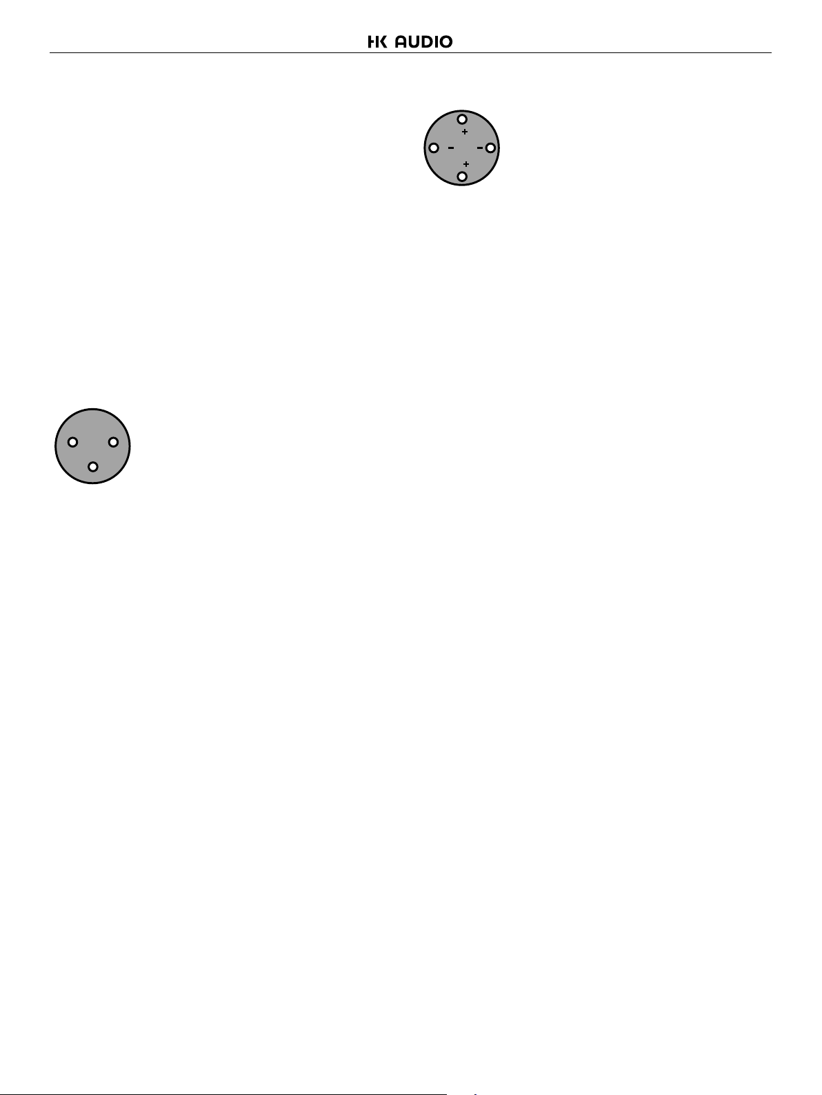
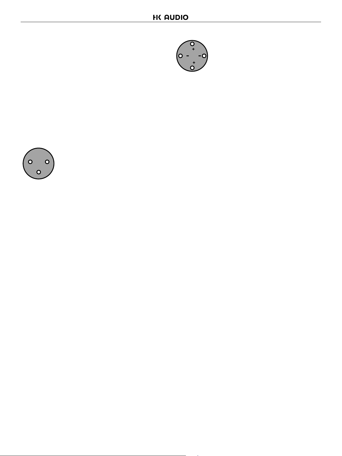
The inputs are made via 3-pin XLR connectors, which are electronically
balanced and should be connected via a high grade twin core screened
cable, as follows:
XLR MALE:
2 1
3
PIN 1: Screen (see note)
PIN 2: Hot (signal +)
PIN 3: Cold (signal -)
The amplifier is designed to operate with fully balanced equipment and
ground loops or loss of performance may be experienced if connected
to unbalanced sources. If it is unavoidable however, the following wiring
should be used. The cable should still be twin core plus screen.
SPEAKON NL2 & NL4
1
21
2
PIN 1+: Hot
PIN 1-: Cold
Additionally Channel A Speakon connector carries Channel B output on
Pins +2 & -2 to allow easy bi-amping or bridged operation using a single
NL4 connector. Similarly, Channel C’s Speakon connector also carries
Channel D output.
Output Connector A
PIN 2+: Hot Ch. B
Pin 2-: Cold Ch. B
Output Connector C
PIN 2+: Hot Ch. D
PIN 2-: Cold Ch. D
For bi-amped operation, connect as above.
There must be no shared connections between channels. Negative
output terminals must not be joined together as they are not both at
ground potential. Connecting them together will damage the amplifier
and void the warranty!
As the currents involved are very high, and to ensure best performance,
the speaker cables should be kept as short as possible and conform to
the following minimum requirements:
20 A into 4 Ohm speaker loads
PIN 1: Screen - connected to the chassis of the unbalanced equipment
– or left disconnected at the unbalanced end.
PIN 2: Hot (signal +)
PIN 3: Cold (ground 0V)
NOTE: This amplifier is wired to the latest industry recommendations.
PIN 1 is connected directly to the chassis/mains earth. If ground loops
(mains hum) are encountered remove the screen connection from the
other end of the cable and leave it open circuit. If problems persist,
consult your dealer/supplier.
DO NOT TAMPER WITH OR ALTER ANY GROUND (EARTH)
CONNECTIONS INSIDE THE AMPLIFIER.
For bridged operation input should be made to channel A (or C) only
and the rear panel switch set for bridged mode for the appropriate pair
of channels.
2.2 Speaker Outputs
The speaker outputs are via Neutrik Speakon connectors. 2 pole
(NL2FC) or 4 pole (NL4FC) connectors can be used.
When operating the amplifier into loads of less than 4 Ohms, be aware
that the current capacity of the speaker cables will need to be increased
above the values quoted here. Do not connect the inputs/outputs to any
other voltage source such as a battery, mains source or power supply,
regardless of whether the amplifier is turned on or off. Do not run the
output of any amplifier channel back into another channel’s input and
do not parallel or series-connect an amplifier output with any other
amplifier output.
2.3 Bridged (Mono) Operation
Pairs of channels may be independently bridged — channel pair A&B,
and/or channel pair C&D. The method is the same for both channel
pairs: Supply signal to Channel A or C input only and push in the
appropriate rear panel switch marked “Bridge A&B” or “Bridge C&D”.
Use Channel A or C’s Output Speakon connector and connect as
follows:
PIN 2+: Hot
PIN 1-: Cold
When operating in bridged mode, the minimum impedances are
doubled. The minimum load in bridged mode is 4 ohms.
4
Page 5
CPQ 10 1.0
3. Operating Your Amplifier
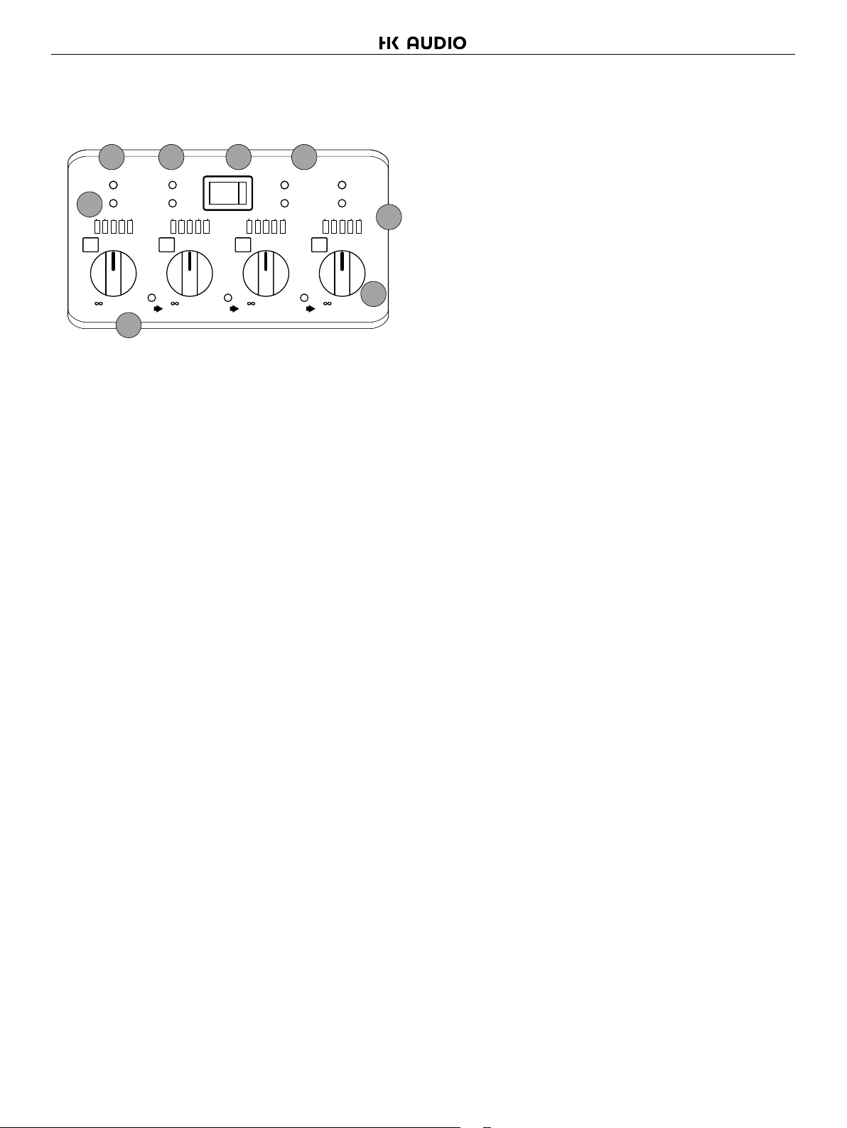
3.1 Front Panel Controls and Indicators
187 2
Bridge A-B
PRC A
6
-24 -16 -6 - 3 L im
-6
A
-12
-20
-
dB dBdB dB
A/P
PRC B
-24 -16 -6 - 3 L im -24 - 16- 6 -3 Li m -24 - 16- 6 -3 L im
OCM
B
-4
-12
-2
-20
0
-
Link
OCM
-6
-4
-12
-2
-20
0
Link
Power
PRC C
OCM
-6
C
-4
0
-
Link
Bridge C-D
PRC D
3
OCM
-6
D
-12
-2
-20
-4
-2
4
0
-
5
1 Power Switch: This single pole switch turns the amplifier fully off (but
does NOT isolate it from the mains supply).
2 Power LED: This indicates when the amplifier is active. This does
NOT indicate the presence of a mains supply when the power switch
is OFF.
3 Signal Meter and OCM indicators: These LED bar graphs show
instantaneous level on each channel to indicate proximity to the limiter
threshold. Note that if the PRC system is in operation on any channel,
this will affect the readout shown on the respective meter. The red
LED in the meter will illuminate when the limiter threshold has been
reached and limiting is occurring. The output current monitor (OCM)
may activate to limit the output current of the amplifier channel - this
can occur even if the amplifier has not reached clipping point.
The OCM indicator can operate independently of the bar graph meter.
Typical conditions that may trigger the OCM circuitry would be very
low load impedance, or high subsonic or VHF levels.
4 Attenuation Controls: These are analogue controls allowing precise
level settings. Note that in bridged (mono) mode some controls may
be inactive.
5 Link LED: This indicates if the channel is linked to its immediate
neighbour. If this is illuminated, the attenuation control of the channel
to the immediate right will not function as both channels are being fed
from the left hand channel. The link switches are on the rear panel —
see chapter 3.3 for details.
Typical conditions that could cause the protection to be triggered
include very high frequency or subsonic input signals, DC in the
inputs, short-circuited outputs, or internal high temperatures.
The protection circuit can affect all channels or a ‘channel pair’
depending on the type of fault. This is indicated by the combination of
A/P LED and OCM LED illuminating. In this way it is possible for two
channels (a channel pair) to remain functioning even though a fault has
caused the other channel pair to mute. A channel pair would be A&B
or C&D.
Temperature related faults will reset if the unit has cooled sufficiently.
Output short circuits will require manual reset after clearing the fault.
Short circuits on either channel of a channel pair will only affect that
channel pair. A/P will illuminate together with the OCM LED on the
shorted channel and the partner channel of the channel pair (so A&B
or C&D).
3.2 Notes and Switching On
Read all documentation before operating your equipment and retain all
documentation for future reference. Do not spill water or other liquids
into or on the unit and do not operate the unit while standing in liquid.
Do not block fan intake or rear ventilation outlets or operate the unit in
an environment that could impede the free flow of air around the unit.
If the unit is used in an extremely dusty or smoky environment, it should
be cleaned of any collected debris at regular intervals. Please also see
the notes regarding maintenance on chapter 4.1.
It is important that the power output of your amplifier is matched to
the power handling capacity of your loudspeaker. If not, damage to the
loudspeaker could occur.
Switching On
At ‘switch-on’ the protection circuit will initially activate whilst the
circuits stabilise, indicated by the red A/P LED illuminating, in addition
to various other LEDs. After a few seconds the red A/P LED will
extinguish indicating a satisfactory working condition. Other LEDs
may remain illuminated depending upon rear panel switch settings and
input connections. If the A/P LED does not extinguish after 5 seconds
the unit may be faulty or some external connections may be incorrect
or inappropriate. If this occurs you should power down the unit and
remove all external connections (except for the mains power supply) and
repeat the power up sequence.
6 PRC LED: This illuminates if the Power Reduction Control has been
enabled on the respective channel. PRC switches are on the rear
panel — see chapter 3.3 for details.
7 Bridge LED: This illuminates when a channel pair have been switched
into bridged (mono) mode (channel A&B or C&D). Note that the partner
channel’s LEDs and controls are disabled when a pair of channels are
bridged. Bridge switches are on the rear panel — see chapter 3.3 for
details of how to connect your speaker to a bridged channel pair.
8 A/P (Auto Protect) LED: If a condition exists, either internally or
externally, that could cause damage to either the amplifier or the
speakers, the protection circuit will disengage the outputs and the
A/P LED will illuminate. The amplifier will continue to be monitored
and depending on the type of fault, will either reset after the fault
has cleared or require manual resetting by switching off at the mains
switch and then on again after a few seconds.
• English • Deutsch • Français • Italiano • Español
5
Page 6
CPQ 10 1.0
PRC
Inpu t
C
Link
B&C
Outp u t
PRC
B
3 4
Link
A&B
S2S1
PRC
S2S1
A
Bridge
A&B
2
1
Output Co nnections
D C B A
1+
D+ C+ B+ A+
1–
D– C– B– A–
2+
D+ B+
B–
D–
2–
Class 3 Wiring o n Outputs
ABCD
Bridge
PRC
C&D
230 V~ 50/60 Hz
Current Consumpti on
15 A
D
Link
C&D
S2S1
PRC
S2S1
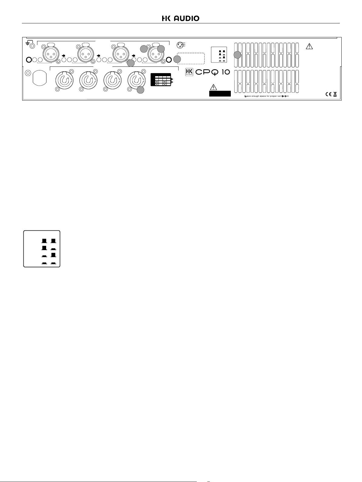
3.3 Rear Panel Sockets and Switches
1 Channel A output Speakon socket: Normal output is on pins 1+
hot, 1- cold. Channel B’s output is also wired to this socket to enable
a single NL4 to provide both channels and to facilitate easier wiring
in bridged mode. Channel B is wired pins 2+ hot, 2- cold. Similarly
channel C’s output Speakon socket carries Channel D’s output. Check
the table on the rear panel for details.
2 Link switch: Press this switch to link the input of the channel to its
immediate left. Multiple channels may be linked using these switches
so, for example, to link all outputs to input A, press all three switches
IN and use input A only. The front panel attenuators will still operate
independently when channels are linked.
3 PRC switches: Each channel of the amplifier may be power limited
independently using these pairs of switches in three stages, offering 2,
4 and 6 dB of Power Reduction Control.
S1 S2
0 dB
–2 dB
–4 dB
–6 dB
The settings for these switches are on the rear panel for quick reference.
4 Input XLR sockets: Connect signal inputs to these sockets, wired
pin2 hot, 3 cold, 1 ground. For sensitivity and impedance of these
inputs, please see the technical specifications.
PRC
Power R eduction Control
S1 S2
0 dB
–2 dB
–4 dB
–6 dB
CAUTI ON
RISK OF E LECTR IC
SHOCK . DO NOT OPEN.
6
Leav e enou gh spa ce fo r prop er ven tilat ion!
CAUTI ON
All v ents on f ront and r ear o f un it
must not be ob struc ted
Do no t rem ove cover s
This unit must be e arth ed
To redu ce th e ri sk of fire or e lectr ic
shock , do not expos e th is ap parat us
to ra in o r moi sture
To redu ce th e ri sk of fire repla ce t he
the f use with the s ame type
No us er s ervic eable par ts in side.
Refer ser vicin g to qual ified servi ce
perso nel
Mount in rack only.
5
Bridge
Mode
2
1: Gnd
1
2: Sig+
3
3: Sig–
Serial No.
5 Bridged (mono) switch (A&B): Press this switch to run this pair of
amplifier channels in bridged mode. To run C&D bridged, press the
switch on the far left of the panel, beside channel D’s input XLR.
6 Fan outlet: The variable speed fans suck air in through the front vents
and out through the back of the amplifier. Please see maintenance on
chapter 4.1 for recommendations on how to clean this and the front
foam sections.
4. Looking After Your Amplifier
4.1 Maintenance
These maintenance instructions are for use by qualified personnel only.
Before any routine maintenance, please ensure that your amplifier is
disconnected from the mains supply! The filter behind the air intake
apertures on the front of your amplifier should be cleaned or replaced
periodically, e.g. 12-24 months. (Filters in amplifiers located in more
‚dirty‘ atmospheres may require more frequent maintenance). The filter
should be ‚dry‘ cleaned, using a vacuum cleaner preferably. Running
the unit without a filter is not recommended unless it is within a ‚clean
room‘. Replacement filter material is available. If the fan vents on the
rear of the amplifier develop a build-up of dust/debris on the finger
guards, they can be cleaned with a dry paintbrush and a vacuum
cleaner. The casework of the amplifier may be cleaned with a lightly
dampened cloth — do not use any solvents as they will damage the
paint finish and could remove printing. If you have any doubts about
carrying out maintenance, please refer to a service engineer or contact
your local dealer.
6
Page 7
5. Technical Specifications
CPQ 10 1.0
5.1 Main Specifications
Output Power per channel [Crest Factor = 4.8] (Watts)
8 Ohms 1400
4 Ohms 2800
2 Ohms 3700
Output Power per channel bridged [Crest Factor = 4.8] (Watts)
8 Ohms 5300
4 Ohms 7400
THD+N, 4 Ohms (%)
@1 kHz, 1 dB below max output power < 0.08
@20 Hz - 20 kHz, 1 dB below max output power < 0.15
Gain (dB) 26
Sensitivity for max power (dBu) 16.0
Sensitivity for max power (Volts) 4.9
Frequency Response, +0/0.5 dB (Hz) 20 — 20000
Power Consumption, Nominal @ 240 V, 4 Ohms (A) 7.0
Power Consumption, Nominal @ 120 V, 4 Ohms (A) 14.0
Dimensions H x W x D (mm)
Amplifier 88 x 482 x 428
Boxed 230 x 580 x 560
Boxed Shipping — all except UK 250 x 610 x 600
Weight (kgs)
Amplifier 12.0
Boxed — shipping 14.0
5.2 Additional Specifications
Input Impedance — Active Balanced (Ohms) 20k
Input CMRR (dB) > 60
SNR (dB) 105
Damping Factor, 1 kHz, 8 Ohms > 400
Signal Limiters Present Yes
Protection Present — Short Circuit / DC Output / Temperature Yes
Mains In-rush Control Present Yes
Output Power per channel, 8 Ohms (Watts)
Sine Wave @ 1 kHz 1150
Continuous music [Crest Factor of 2.8 or 9 dB] 1300
Continuous music [Crest Factor of 4.8 or 14 dB] 1400
Continuous music [Crest Factor of 7.8 or 18 dB] 1480
Output Power per channel, 4 Ohms (Watts)
Sine Wave @ 1 kHz 2250
Continuous music [Crest Factor of 2.8 or 9 dB] 2600
Continuous music [Crest Factor of 4.8 or 14 dB] 2800
Continuous music [Crest Factor of 7.8 or 18 dB] 2900
Output Power per channel, 2 Ohms (Watts)
Sine Wave @ 1 kHz 3200
Continuous music with Crest Factor of 2.8 [9 dB] 3600
Continuous music with Crest Factor of 4.8 [14 dB] 3700
Continuous music with Crest Factor of 7.8 [18 dB] 3700
5.4 PRC Settings and Maximum Output
Power Reduction Control Setting Per Channel Bridged Pair
Maximum Power into 8 Ohms (W) 1400 5300
-2 dB PRC 980 3700
-4 dB PRC 560 2100
-6 dB PRC 310 1175
Maximum Power into 4 Ohms (W) 2800 7400
-2 dB PRC 1950 5160
-4 dB PRC 1110 2940
-6 dB PRC 620 1640
Maximum Power into 2 Ohms (W) 3700 N/A
-2 dB PRC 2580 N/A
-4 dB PRC 1470 N/A
-6 dB PRC 820 N/A
Due to continuing product improvement the above specifications are subject to change.
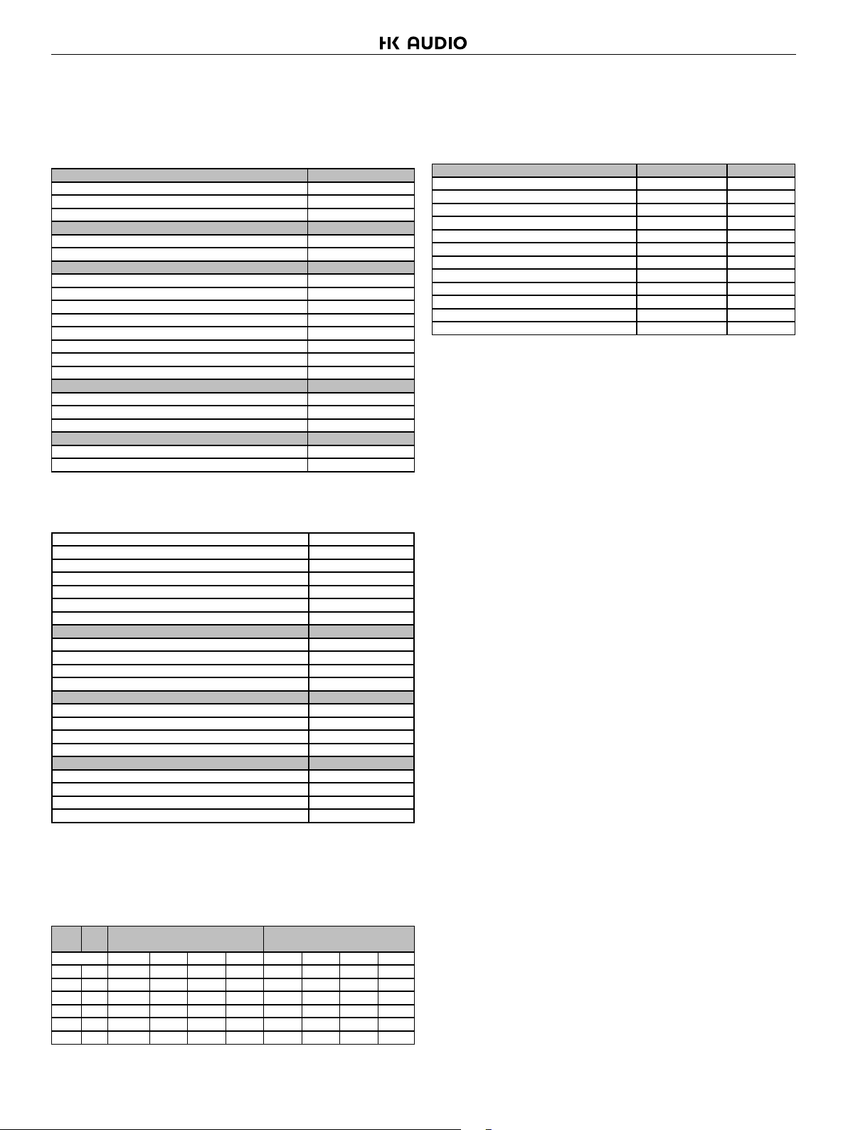
5.3 Power Consumption and Thermal
Emissions
Mains
Load
(V)
(R)
240 8 2.1 3.0 4.5 8.3 504 528 566 660
240 4 2.1 3.9 7.0 14.4 504 551 628 816
240 2 2.1 4.5 8.6 19.1 504 564 668 936
120 8 4.2 6.0 9.0 16.6 504 528 566 660
120 4 4.2 7.8 14.0 28.8 504 551 628 816
120 2 4.2 9.0 17.2 38.2 504 564 668 936
No Sig’l = Quiescent, Light = Crest Factor of 7.8 (18 dB),
Average = Crest Factor of 4.8 (14 dB), Heavy = Crest Factor of 2.8 (9 dB)
Current Draw (A) Thermal Emissions (W)
No Sig’l Light Average Heavy No Sig’l Light Average Heavy
• English • Deutsch • Français • Italiano • Español
7
Page 8
Wichtige Sicherheitshinweise! Bitte vor
Anschluss lesen!
Dieses Produkt wurde gemäß IEC 60065 hergestellt und hat
das Werk in einem sicheren, betriebsfähigen Zustand verlassen.
Um diesen Zustand zu erhalten und um einen gefahrlosen
Betrieb zu gewährleisten, ist es notwendig, dass der Benutzer
die Empfehlungen und Warnhinweise befolgt, die in der
Betriebsanleitung zu finden sind. Bei Einsatz dieses Produktes
in Fahrzeugen, Schiffen oder Flugzeugen, oder in Höhen
oberhalb 2000 m Meereshöhe müssen die entsprechenden
Sicherheitsstandards zusätzlich zur IEC 60065 beachtet werden.
WARNUNG: Um das Risiko von Feuer oder Stromschlag zu
verhüten, darf dieses Gerät nicht Feuchtigkeit oder Regen
ausgesetzt werden. Öffnen Sie das Gehäuse nicht – im Inneren
gibt es keine Bauteile, die vom Benutzer wartbar sind. Die
Wartung darf nur von einem qualifiziertem Kundendienst
durchgeführt werden.
Dieses Symbol, wo immer es erscheint, warnt Sie vor
gefährlicher, nicht isolierter Spannung im Gehäuse – Spannung,
die möglicherweise genügt, eine Stromschlaggefahr darzustellen.
Dieses Symbol, wo immer es erscheint, warnt Sie vor
außen zugänglicher, gefährlicher Spannung. Eine Verbindung zu
jeder Anschlussklemme, die mit diesem Symbol versehen ist, darf
nur mit konfektioniertem Kabel hergestellt werden, dass den
Empfehlungen des Herstellers genügt, oder mit Kabel, das von
qualifiziertem Personal installiert wurde.
Dieses Symbol, wo immer es erscheint, macht Sie auf
wichtige Bedienungs- und Wartungsanweisungen aufmerksam,
die in beiliegenden Unterlagen zu finden sind. Bitte lesen Sie das
Handbuch.
Dieses Symbol, wo immer es erscheint, sagt Ihnen:
Vorsicht! Heiße Oberfläche! Um Verbrennungen zu vermeiden,
nicht anfassen.
• Bitte lesen Sie diese Anweisungen.
• Bewahren Sie diese Anweisungen auf.
• Befolgen Sie alle Warnhinweise und Anweisungen auf dem
Gerät und in dieser Anleitung.
• Benutzen Sie dieses Gerät nicht in der Nähe von Wasser. Stellen
Sie das Gerät nicht in der Nähe von Wasser, Badewannen,
Waschbecken, Küchenspülen, nassen Stellen, Schwimmbecken
oder feuchten Räumen auf.
• Stellen Sie keine Gefäße, wie Vasen, Gläser, Flaschen usw., die
Flüssigkeiten enthalten, auf das Gerät.
• Reinigen Sie das Gerät nur mit einem trockenen Tuch.
• Entfernen Sie keine Abdeckungen oder Teile des Gehäuses.
• Die auf dem Gerät eingestellte Betriebsspannung muss mit der
örtlichen Spannung der Netzstromversorgung übereinstimmen.
Wenn Sie sich nicht sicher sind, welche Spannung in Ihrem
Netz zur Verfügung steht, konsultieren Sie bitte Ihren Händler
oder den örtlichen Stromversorger.
• Um das Risiko eines Stromschlags zu verringern, muss die
Erdung des Gerätes beibehalten werden. Verwenden Sie nur das
mitgelieferte Stromführungskabel und behalten Sie die Funktion
der seitlichen, geerdeten Schutzkontakte des Netzanschlusses
immer aufrecht. Versuchen Sie nicht, die Sicherheitsaufgabe
des geerdeten Steckers zu umgehen.
• Schützen Sie das Stromführungskabel vor Betreten
und Quetschen, besonders in der Nähe der Stecker,
Gerätesteckdosen – und dort, wo sie am Gerät austreten!
Stromführungskabel sollten immer vorsichtig behandelt werden.
Kontrollieren Sie die Stromführungskabel in regelmäßigen
Abständen auf Einschnitte und Anzeichen von Abnutzung,
besonders in der Nähe des Steckers und an der Verbindung
zum Gerät.
• Benutzen Sie niemals ein beschädigtes Stromführungskabel.
• Ziehen Sie bei Gewittern den Stecker des Gerätes und wenn
das Gerät über einen längeren Zeitraum nicht benutzt wird.
• Dieses Gerät wird nur vollständig von Stromnetz getrennt, wenn
der Stecker vom Gerät oder aus der Steckdose gezogen wird.
Das Gerät sollte so aufgestellt werden, dass das Trennen vom
Stromnetz leicht möglich ist.
• Sicherungen: Ersetzen Sie Sicherungen nur mit dem Typ IEC127
(5x20mm) und dem korrekten Nennwert, um die optimale
Leistung zu gewährleisten! Es ist untersagt, kurzgeschlossene
Sicherungen zu verwenden oder den Sicherungshalter zu
überbrücken. Sicherungen dürfen nur von qualifiziertem
Personal gewechselt werden.
• Alle Wartungsarbeiten sollten nur von qualifiziertem Personal
ausgeführt werden. Wartung ist notwendig, wenn das Gerät auf
irgendeine Weise beschädigt wurde, wie zum Beispiel:
- Wenn das Stromführungskabel oder der Stecker beschädigt
oder abgenutzt ist.
- Wenn Flüssigkeit oder Gegenstände in das Gerät gelangt sind.
- Wenn das Gerät Regen oder Feuchtigkeit ausgesetzt war.
- Wenn das Gerät nicht ordnungsgemäß funktioniert, obwohl die
Bedienungsanleitung beachtet wurde.
- Wenn das Gerät hingefallen ist oder das Gehäuse beschädigt
wurde.
• Beim Anschluss von Lautsprechern an dieses Gerät darf
die auf dem Gerät oder in dieser Anleitung angegebene
Mindestimpedanz nicht unterschritten werden. Die verwendeten
Kabel müssen entsprechend den lokalen Regelungen über einen
ausreichenden Querschnitt verfügen.
• Halten Sie das Gerät vom Sonnenlicht fern.
• Installieren Sie das Gerät nicht in der Nähe von Wärmequellen,
wie zum Beispiel Heizkörper, Heizregister, Öfen oder anderen
Geräten, die Hitze erzeugen.
• Verstopfen Sie nicht die Lüftungsöffnungen. Installieren Sie
das Gerät entsprechend der Anleitung des Herstellers. Das
Gerät darf nicht eingebaut werden – wie zum Beispiel in einen
Gestellrahmen, es sei denn, dass für angemessene Belüftung
gesorgt wird.
• Ein kaltes Gerät sollte immer auf die Umgebungstemperatur
erwärmt werden, wenn es in einen Raum transportiert wird.
Es könnte sich Kondensation im Inneren bilden, die das Gerät
beschädigt, wenn es ohne vorherige Erwärmung benutzt wird.
• Stellen Sie keine offenen Flammen, wie brennende Kerzen, auf
das Gerät.
• Das Gerät sollte mindestens 20 cm von Wänden aufgestellt
werden.
• Das Gerät darf nur mit Rollwagen, Ständern, Stativen,
Tischen oder Halterungen benutzt werden, die vom Hersteller
spezifiziert sind oder zusammen mit dem Gerät verkauft
wurden. Wenn ein Rollwagen benutzt wird, seien Sie vorsichtig,
wenn Sie die Rollwagen/Geräte-Kombination transportieren, um
Verletzungen durch Umkippen zu vermeiden.
• Verwenden Sie nur Zubehör, das vom Hersteller empfohlen
ist. Das gilt für alle Arten von Zubehör, wie zum Beispiel
Schutzabdeckungen, Transporttaschen, Ständer sowie Wandund Deckenhalterungen. Wenn Sie irgendein Zubehör am Gerät
anbringen, befolgen Sie immer die Anleitungen des Herstellers.
Benutzen Sie nur die Befestigungspunkte des Geräts, die vom
Hersteller vorgesehen sind.
• Dieses Gerät ist NICHT geeignet für eine Person oder Personen
(einschließlich Kindern) mit eingeschränkten physischen,
sensorischen und geistigen Fähigkeiten, oder für Personen mit
unzulänglicher Erfahrung und/oder Fachkenntnis, um solch
ein Gerät zu bedienen. Kinder unter 4 Jahren sollten stets von
diesem Gerät fern gehalten werden.
• Es sollten keinerlei Gegenstände durch die Gehäuseschlitze
eingeführt werden, da dadurch gefährliche, spannungsführende
Bauteile berührt oder kurzgeschlossen werden können. Dies
könnte zu einer Feuer- oder Stromschlaggefahr führen.
• Dieses Gerät ist imstande, Schalldruckpegel von mehr als
90 dB zu produzieren. Dies könnte zu einem dauerhaften
Hörschaden führen! Eine Belastung durch extrem hohe
Geräuschpegel kann zu einem dauerhaften Gehörverlust führen.
Bei einer anhaltenden Belastung durch solch hohe Pegel sollte
ein Gehörschutz getragen werden.
• Der Hersteller gewährleistet die Sicherheit, Zuverlässigkeit und
Leistung des Gerätes nur unter folgenden Voraussetzungen:
- Einbau, Erweiterung, Neueinstellung, Modifikationen oder
Reparaturen werden vom Hersteller oder autorisiertem Personal
ausgeführt.
- Die elektrische Installation des betreffenden Bereiches
entspricht den Anforderungen der IEC (ANSI) Maßgaben.
- Das Gerät wird entsprechend der Bedienungsanleitung benutzt.
- Das Gerät wird regelmäßig von einem fachkundigen Techniker
auf elektrische Sicherheit geprüft und getestet.
Allgemeine Sicherheitshinweise für
Lautsprechersysteme
Befestigungssysteme dürfen ausschließlich für die vom
Hersteller freigegebenen Lautsprechersysteme und mit dem in
der Montageanleitung genannten Montage-Zubehör verwendet
werden. Die Montagehinweise des Herstellers sind dabei
unbedingt zu beachten. Bei unsachgemäßer Montage bzw.
Verwendung von nicht freigegebenem Montage-Zubehör kann die
angegebene Belastung nicht garantiert und keinerlei Haftung
seitens des Herstellers übernommen werden.
Sollten Änderungen an Lautsprechern, an Montage-Zubehör,
Verbindungs- und Befestigungselementen sowie Anschlagmitteln
vorgenommen werden, kann die Tragfähigkeit des Systems nicht
mehr garantiert werden und seitens des Hersteller keinerlei
Haftung übernommen werden.
Reparaturen an sicherheitsrelevanten Bauteilen dürfen nur
vom Hersteller oder Bevollmächtigten durchgeführt werden,
andernfalls erlischt die Betriebserlaubnis.
Die Installation darf ausschließlich durch Sachkundige und
nur an Montagepunkten mit ausreichender Tragfähigkeit, ggf.
unter der Berücksichtigung von Bauauflagen, erfolgen. Das vom
Hersteller in der Montageanleitung vorgeschriebene
Befestigungsmaterial (Schrauben, Dübel, etc.) muss verwendet
werden. Schraubverbindungen müssen durch geeignete
Maßnahmen gegen Lösen gesichert sein.
Ortsfeste oder mobile Installationen (hier Lautsprecher inkl.
Montagezubehör) müssen durch zwei unabhängig voneinander
wirkende Einrichtungen gegen Herabfallen gesichert sein. Lose
Zusatzteile oder sich lösende Teile müssen durch geeignete
Einrichtungen aufgefangen werden können. Bei Verwendung von
Verbindungs- und Befestigungselementen sowie Anschlagmitteln
sind die nationalen Vorschriften zu beachten. Hinsichtlich der
Bemessung der Sicherungsmittel sind mögliche dynamische
Belastungen (Ruckkräfte) mit zu berücksichtigen.
Bei Stativen ist vor allem die maximale Traglast zu
beachten. Außerdem sind die meisten Stative aus konstruktiven
Gründen nur für das Tragen von genau zentrischer Belastung
zugelassen. Stative müssen standsicher aufgestellt werden.
Stative sind durch geeignete Maßnahmen zusätzlich zu sichern,
wenn zum Beispiel:
- ihre Aufstandfläche keinen sicheren Stand zulässt,
- ihre Höhen die Standsicherheit einschränken,
- mit zu hohem Winddruck zu rechnen ist,
- damit zu rechnen ist, dass sie durch Personen umgestoßen
werden.
Besondere Maßnahmen können auch zur Vorsorge gegen
gefährdendes Verhalten von Zuschauern erforderlich werden.
Stative dürfen nicht in Flucht- und Rettungswegen aufgestellt
werden. Bei Aufstellung in Verkehrswegen ist auf die erforderliche
Breite der Wege und auf ordnungsgemäße Absperrung sowie
Kennzeichnung zu achten. Beim Auf- und Absetzen ist eine
besondere Gefährdung gegeben. Hierzu sind geeignete Hilfsmittel
zu verwenden. Es sind hierbei die nationalen Vorschriften zu
beachten.
Während der Montage ist geeignete Schutzausrüstung
(insbesondere Kopfschutz, Handschuhe und Sicherheitsschuhe) zu
tragen und es sind nur geeignete Aufstiegshilfen (Leitern,
Gerüste, etc.) zu verwenden. Die Verantwortung dafür liegt alleine
beim ausführenden Installationsbetrieb.
Nach der Montage ist die Aufhängung des System aus
Halterung und Lautsprecher auf sichere Befestigung zu
überprüfen.
Der Betreiber von Lautsprechersystemen (ortsfest oder mobil) ist
verpflichtet, alle Systemkomponenten unter Berücksichtigung der
jeweils nationalen Regelungen regelmäßig zu überprüfen bzw.
prüfen zu lassen und mögliche Schäden unverzüglich beseitigen
zu lassen.
Weiterhin raten wir dringend zu einer ausführlichen
Dokumentation aller Überprüfungsmaßnahmen
in Prüfbüchern o.ä.
Beim Einsatz von Lautsprechern im Freien sind für
Standsicherheit und Tragfähigkeit von Aufbauten und Flächen
insbesondere auch die Windlasten, Schnee- und Eislasten
sowie thermische Einflüsse zu berücksichtigen. Insbesondere
die Lastaufnahmepunkte geflogener Systeme sollten hier mit
ausreichenden Sicherheitsreserven dimensioniert werden. Es sind
hierbei die nationalen Vorschriften zu beachten.
Professionelle Lautsprechersysteme sind in der Lage,
gesundheitsschädliche Schallpegel zu erzeugen. Selbst die
Einwirkung scheinbar harmloser Schallpegel über einen längeren
Zeitraum kann zu bleibenden Schäden am Gehör führen (ab ca.
95 dBA SPL)! Daher raten wir für alle Personen, die durch den
Betrieb von Lautsprechersystemen dem Einfluss hoher
Schallpegel ausgesetzt sind, zum Tragen von professionellem
Gehörschutz (Ohrstöpsel oder Kapselgehörschutz).
Hersteller: Stamer Musikanlagen GmbH, Magdeburger Str. 8,
66606 St. Wendel, Deutschland
Version 2.2 01/2011
Page 9
Bridge A-B
A/P
PRC A
-24 -16- 6 -3 Lim
A
-12
-20
PRC B
-24 -16- 6 -3 Lim -24 -16 -6 -3 Lim -24 -16 -6 -3 Li m
OCM
-6
-4
0
-
dB dBdB dB
OCM
-6
B
C
-4
-12
-2
Link
-12
-2
-20
-20
0
-
-
Link
CPQ 10 1.0
Power
Bridge C-D
PRC C
PRC D
OCM
-6
-4
0
Link
OCM
-6
D
-4
-12
-2
-2
-20
0
-
INHALT
1. Aufstellung und Einbau der CPQ 10 ........................................9
1.1 Elektrische Eigenschaften ..........................................................9
1.2 Mechanische Eigenschaften .......................................................9
1.3 HF-Abstrahlung ........................................................................10
2. Anschluss der CPQ 10 ............................................................10
2.1 Eingänge ..................................................................................10
2.2 Ausgänge .................................................................................10
2.3 Bridged-Betrieb (Mono) ............................................................10
3. Bedienung der CPQ 10 ...........................................................11
3.1 Bedienelemente und Anzeigen an der Frontplatte ....................11
3.2 Hinweise und Einschalten .........................................................11
3.3 Buchsen und Schalter auf der Rückseite..................................12
4. Pflege der CPQ 10 ..................................................................12
4.1 Wartung ....................................................................................12
5. Technische Daten ...................................................................13
1. Aufstellung und Einbau
der CPQ 10
1.1 Elektrische Eigenschaften
• Diese Endstufe wurde gemäß den Anforderungen der in Ihrem Land
üblichen Stromversorgung gefertigt. Stellen Sie sicher, dass die
verfügbare Spannungsversorgung den auf der Rückseite des Gerätes
aufgeführten Anforderungen entspricht. Für Schäden, die durch
Anschließen an eine ungeeignete Spannung entstehen, wird keine
Haftung übernommen.
SICHERHEITSHINWEISE
• Falls Sie einen Netzstecker oder eine Mehrfachsteckdose verwenden,
um das Gerät von der Stromversorgung zu trennen, sollten Sie
sicherstellen, dass Sie jederzeit darauf zugreifen können. Falls die
Endstufe in ein Rack montiert wird, wo sie permanent mit dem Netz
verbunden ist, sollte das Rack mit einem leicht zugänglichen Stecker
oder einem allpoligen Schutzschalter ausgestattet sein.
• Dieses Gerät verfügt über ein dreiadriges Stromversorgungskabel.
AUS SICHERHEITSGRÜNDEN SOLLTE DIE ERDUNG UNTER KEINEN
UMSTÄNDEN UNTERBROCHEN WERDEN. Sollten Masseschleifen
auftreten, so lesen Sie bitte das Kapitel „2. Anschluss der CPQ 10“.
Kennzeichnungsfarben der Kabel:
IN LÄNDERN MIT 220-240 V:
SCHUTZLEITER = GRÜN UND GELB
NULLLEITER = BLAU
PHASE = BRAUN
IN LÄNDERN MIT 120 V:
SCHUTZLEITER = GRÜN
NULLLEITER = WEISS
PHASE = SCHWARZ
• BENUTZEN SIE DAS GERÄT NICHT, WENN DAS KABEL BESCHÄDIGT
ODER BRÜCHIG IST. Die Kabel zur Stromversorgung sollten so verlegt
werden, dass niemand darauf tritt oder die Kabel eingeklemmt werden.
Besondere Aufmerksamkeit sollte den Punkten gewidmet werden, wo
Kabel und Stecker direkt aus dem Gerät herausragen.
• BEI BETRIEB SOLLTE DER SCHUTZLEITER STETS MIT DER ERDUNG
DES ELEKTRISCHEN SYSTEMS VERBUNDEN SEIN. Insbesondere
sollte darauf geachtet werden, dass die Erdung von jeglichem
anderem Equipment erhalten bleibt.
• DIE ABDECKUNG NICHT ENTFERNEN. Durch Entfernen der
Abdeckung setzen Sie sich einer Gefährdung durch hohe Spannungen
aus. Innerhalb des Gehäuses gibt es keinerlei vom Anwender zu
wartende Teile.
• Elektrostatische Entladungen an der Frontplatte, die 4.000 Volt
überschreiten, können Störungen an den Status-LEDs des Geräts
verursachen. Diese haben jedoch keinen Einfluss auf die Audioleistung
und werden beim nächsten Einschalten des Geräts behoben.
1.2 Mechanische Eigenschaften
• Damit dieses Gerät wie angegeben funktioniert, sollte es wie
nachfolgend beschrieben in ein geeignetes Rack oder Gehäuse
eingebaut werden. Das Gerät sollte wie andere High-Power-Endstufen
von Equipment ferngehalten werden, das gegen Magnetfelder
empfindlich ist.
• Warnhinweis: Um Verletzungen zu vermeiden, muss dieses Gerät
sicher in einem Rack befestigt sein.
• Bei Einbau der Endstufe in ein Rack oder Gehäuse bitte beachten:
• DIE FRONTPLATTE ALLEIN REICHT NICHT AUS, UM DAS GERÄT
SICHER IN POSITION ZU HALTEN: Sorgen Sie dafür, dass das Gerät
auch an der Rückseite ausreichend unterstützt wird. Die mitgelieferten
Winkel eignen sich für Standard-19-Zoll-Rackmounting-Systeme
(483mm).
• SORGEN SIE FÜR AUSREICHENDE FRISCHLUFTZUFUHR: Die
Kühlventilatoren saugen an der Frontseite Frischluft an und blasen
die erwärmte Luft durch die Lüftungsgitter auf der Rückseite aus dem
Gerät heraus. Vor und hinter der Endstufe sollte daher genügend
Raum verfügbar sein (d.h. Abdeckung vorne und hinten offen lassen);
an den Seiten sollte der Luftspalt mindestens 2 cm betragen.
• FALLS AUF DER RÜCKSEITE KEINE LUFT ENTWEICHEN KANN,
KOMMT ES ZU ÜBERHITZUNG.
• Sorgen Sie dafür, dass das Rack über eine separate Erdung
(technische Erdung) verfügt.
• Bitte beachten Sie auch die Hinweise zu Pflege und Wartung in
Kapitel4.1.
• English • Deutsch • Français • Italiano • Español
9
Page 10
CPQ 10 1.0
1.3 HF-Abstrahlung
• Die Ausgangsfilter der CPQ 10 sind für geringe HF-Abstrahlung
ausgelegt; allerdings können auch solche geringen Abstrahlungen
anderes Equipment beeinträchtigen.
• Um Beeinträchtigungen möglichst gering zu halten, sollte die Endstufe
in ein Rack-Gehäuse aus Metall mit separater Erdung (technische
Erde) eingebaut werden. Alternativ sollte am hinteren RackMontagewinkel eine separate Erdung angebracht werden.
2. Anschluss der CPQ 10
2.1 Eingänge
Für die Eingänge stehen elektronisch symmetrierte 3-Pin-XLRAnschlussbuchsen zur Verfügung. Für den Anschluss sollten
hochwertige abgeschirmte Twincore-Kabel wie folgt verwendet werden:
XLR MALE:
2 1
3
PIN 1: Abschirmung (siehe Anmerkung)
PIN 2: Heiß (Signal +)
PIN 3: Kalt (Signal -)
Die Endstufe ist für den Betrieb mit vollsymmetriertem Equipment
ausgelegt. Beim Anschluss an unsymmetrische Signalquellen kann es
zu Masseschleifen oder Leistungsverlusten kommen. Sofern dies jedoch
unvermeidbar ist, sollte die folgende Belegung verwendet werden, dabei
sollte es sich ebenfalls um ein abgeschirmtes Twincore-Kabel handeln:
PIN 1: Abschirmung – mit dem Gehäuse des unsymmetrischen
Equipments verbunden – oder auf der unsymmetrischen Seite
nicht angeschlossen.
PIN 2: Heiß (Signal +)
PIN 3: Kalt (Masse / 0 V)
ANMERKUNG: Diese Endstufe entspricht in ihrer Belegung den neusten
Branchenempfehlungen. PIN 1 wird direkt an das Gehäuse/die Erdung
der Stromversorgung angeschlossen. Falls es zu Masseschleifen
(Netzbrummen) kommt, die Abschirmung am anderen Ende des Input
Kabels von der Masse des Audiosystems trennen und als offenen
Schaltkreis belassen. Sollten die Probleme weiter bestehen, wenden Sie
sich bitte an Ihren Händler bzw. Lieferanten.
ERDUNGEN IM INNERN DER ENDSTUFE DÜRFEN NICHT
MANIPULIERT/GEÄNDERT WERDEN.
Bei Bridged-Betrieb sollte der Input über Kanal A (oder C) erfolgen; der
Schalter an der Rückseite muss für das entsprechende Kanalpaar auf
Bridged-Modus gebracht werden.
2.2 Lautsprecherausgänge
Die Lautsprecherausgänge sind als Neutrik Speakon-Anschlussbuchsen
ausgeführt. Es können zweipolige (NL2FC) oder vierpolige (NL4FC)
Stecker benutzt werden.
SPEAKON NL2 und NL4
1
21
2
PIN 1+: Heiß
PIN 1-: Kalt
Zusätzlich liegt an den Pins +2 und -2 der Speakon-Buchse von KanalA
der Output von Kanal B an. Durch die Verwendung einer einzigen NL4Steckverbindung wird Bi-amping oder Bridged-Betrieb vereinfacht.
Ebenso führt die Speakon-Buchse von Kanal C das Output-Signal von
Kanal D.
Ausgang Anschlussbuchse A
PIN 2+: Heiß, Kanal B
PIN 2-: Kalt, Kanal B
Ausgang Anschlussbuchse C
PIN 2+: Heiß, Kanal D
PIN 2-: Kalt, Kanal D
Für Bi-amped-Betrieb muss der Anschluss wie oben genannt erfolgen.
Es darf keine von beiden Kanälen gemeinsam genutzten Anschlüsse
geben. Negative Ausgangsanschlüsse dürfen nicht miteinander
verbunden werden, da beide nicht geerdet sind. Eine solche
Verbindung würde die Endstufe beschädigen – und Sie würden den
Garantieanspruch für das Gerät verlieren.
Da die auftretenden Ströme sehr hoch sind und die Leistung optimal
sein soll, sollten die Lautsprecherkabel möglichst kurz sein und den
folgenden Mindestanforderungen entsprechen:
20 A an 4 Ohm Lautsprecherlast
Wenn die Endstufe mit Lasten von weniger als 4 Ohm betrieben wird,
gilt es zu bedenken, dass die Strombelastbarkeit der Lautsprecherkabel
über die hier genannten Werte hinaus erhöht werden muss. Schließen
Sie die Ein-/Ausgänge weder im ein- noch im ausgeschalteten Zustand
an andere Spannungsquellen wie etwa Batterien, Netzanschlüsse oder
Stromversorgungen an. Leiten Sie den Output eines Endstufenkanals
nicht in einen anderen Kanal zurück und schalten Sie den EndstufenOutput nicht mit einem anderen Endstufen-Output parallel oder in Serie.
2.3 Bridged-Betrieb (Mono)
Kanalpaare können unabhängig voneinander gebrückt werden –
Kanalpaar A und B und/oder Kanalpaar C und D. Die Methode ist für
beide Kanalpaare dieselbe: Speisen Sie das Signal nur in den Eingang
von Kanal A oder C ein. Bringen Sie dazu auf der Rückseite den mit
„Bridge A&B” oder „Bridge C&D” gekennzeichneten Schalter in die ONStellung.
Verwenden Sie an der Ausgangsbuchse von Kanal A oder C einen
Speakon-Stecker mit folgender Belegung:
PIN 2+: Heiß
PIN 1-: Kalt
10
Im Bridged-Modus verdoppeln sich die minimalen Last-Impedanzen. Die
Mindestlast im Bridged-Betrieb beträgt 4 Ohm.
Page 11

CPQ 10 1.0
3. Bedienung der CPQ 10
3.1 Bedienelemente und Anzeigen an der
Frontseite
187 2
Bridge A-B
PRC A
6
-24 -16 -6 - 3 L im
-6
A
-12
-20
-
dB dBdB dB
A/P
PRC B
-24 -16 -6 - 3 L im -24 - 16- 6 -3 Li m -24 - 16- 6 -3 L im
OCM
B
-4
-12
-2
-20
0
-
Link
OCM
-6
-4
-12
-2
-20
0
Link
Power
PRC C
OCM
-6
C
-4
0
-
Link
Bridge C-D
PRC D
3
OCM
-6
D
-12
-2
-20
-4
-2
4
0
-
5
1 Power-Schalter: Dieser schaltet die Endstufe vollständig ab (trennt
sie jedoch nicht vom Netz).
2 Power-LED: Sie zeigt an wenn die Endstufe aktiv ist. Sie zeigt NICHT
an, ob eine Stromversorgung vorhanden ist, wenn der Power-Schalter
auf OFF steht.
3 Signalstärke- und OCM-Anzeigen: Diese LED-Balkengrafiken zeigen
für jeden Kanal den aktuellen Pegel an, um so auf eine mögliche
Annäherung an den Limiter-Schwellenwert aufmerksam zu machen.
Bitte beachten Sie: Falls bei einem Kanal das PRC-System in Betrieb
ist, hat dies Einfluss auf den angezeigten Wert. Die rote LED der
Anzeige leuchtet auf wenn der Limiter-Schwellenwert erreicht ist
und der Limiter aktiv wird. Die Ausgangsstromüberwachung (OCM
= Output Current Monitor) dient dazu, den Ausgangsstrom am
Verstärkerkanal zu begrenzen. Dazu kann es auch kommen wenn die
Endstufe den Clipping-Punkt noch nicht erreicht hat.
Die OCM-Anzeige arbeitet unabhängig von der Balkengrafik-Anzeige.
Zu den typischen Situationen, welche die OCM-Schaltung auslösen
können, gehören sehr niedrige Lastimpedanzen oder extrem tief- bzw.
hochfrequente Signale.
4 Dämpfungsregler: Hierbei handelt es sich um Analogregler für präzise
Pegeleinstellung. Bitte beachten Sie, dass bei Bridged-Betrieb (Mono)
einige Regler ohne Funktion sein können.
5 Link-LED: Die Link-LED zeigt an, ob der Kanal mit seinem
unmittelbaren Nachbarn verbunden ist. Wenn sie leuchtet, ist der
Dämpfungsregler des Kanals unmittelbar rechts ohne Funktion, da
beide Kanäle vom linken Kanal gespeist werden. Die Link-Schalter
befinden sich an der Rückseite – Einzelheiten hierzu in Kapitel 3.3.
nach Fehlertyp erfolgt entweder ein automatischer Reset, nachdem
der Fehler behoben wurde, oder es ist ein manueller Reset durch
Betätigen des Netzschalters erforderlich. Das Gerät kann dann nach
wenigen Sekunden wieder eingeschaltet werden.
Zu den typischen Ereignissen, welche die Schutzschaltung auslösen,
gehören hochfrequente oder Eingangsignale im Infraschallbereich,
kurzgeschlossene Ausgänge oder zu hohe Temperaturen im Innern des
Geräts. Je nach Fehlerart kann sich die Schutzschaltung auf sämtliche
Kanäle oder Kanalpaare auswirken. Zur Anzeige leuchten die A/P- und
die OCM-LEDs auf. Auf diese Weise ist es möglich, dass zwei Kanäle
(oder ein Kanalpaar) weiterhin funktionieren, auch wenn aufgrund des
Fehlers das andere Kanalpaar stummgeschaltet wurde. Ein Kanalpaar
wäre A&B oder C&D.
Temperaturbedingten Ausfällen folgt ein Reset mit automatischem
Neustart, sobald das Gerät ausreichend abgekühlt ist. Kurzschlüsse an
den Ausgängen machen einen manuellen Reset nach Fehlerbehebung
erforderlich. Kurzschlüsse an einem Kanal eines Kanalpaares betreffen
lediglich dieses Kanalpaar. A/P- und OCM-LEDs leuchten sowohl bei
dem kurzgeschlossenen Kanal als auch beim Partnerkanal auf.
3.2 Anmerkungen und Einschalten
Lesen Sie die vorliegende Anleitung sorgfältig durch bevor Sie das Gerät
in Betrieb nehmen und bewahren sie sämtliche Unterlagen für späteres
Nachschlagen auf. Gießen Sie kein Wasser oder andere Flüssigkeiten
über oder in das Gerät, und bedienen Sie das Gerät nicht während
Sie im Nassen stehen. Blockieren Sie weder den Luftein- noch den
Luftauslass und betreiben Sie das Gerät nicht in einer Umgebung, die
den freien Luftfluss in und um das Gerät herum behindert.
Falls das Gerät in einer extrem staubigen oder von Rauch belasteten
Umgebung eingesetzt wird, sollte es in regelmäßigen Abständen von
jeglichen Ablagerungen gereinigt werden. Bitte beachten Sie auch die
Hinweise zu Pflege und Wartung in Kapitel 4.1.
Die Ausgangsleistung der Endstufe sollte stets der Belastbarkeit
des Lautsprechers entsprechen. Falls nicht, kann es zu Schäden am
Lautsprecher kommen.
Einschalten
Beim Einschalten wird zunächst die Schutzschaltung aktiviert bis
sich die Schaltkreise stabilisiert haben. Dies ist unter anderem am
Aufleuchten der roten A/P-LED zu erkennen. Nach wenigen Sekunden
erlischt die rote A/P-LED und signalisiert damit die Betriebsbereitschaft
der Endstufe. Weitere LEDs bleiben unter Umständen je nach den
Schalterstellungen an der Rückseite und den Inputanschlüssen
erleuchtet. Sollte die A/P-LED nach fünf Sekunden nicht erloschen
sein, kann ein interner Fehler vorliegen oder einige externe Anschlüsse
sind fehlerhaft oder ungeeignet. In diesem Fall sollte das Gerät
ausgeschaltet, sämtliche externen Anschlüsse (mit Ausnahme des
Netzkabels) entfernt und der Einschaltvorgang wiederholt werden.
6 PRC-LED: Die PRC-LED leuchtet auf wenn auf dem entsprechenden
Kanal die Power Reduction Control aktiviert wurde. Die PRC-Schalter
befinden sich an der Rückseite – Einzelheiten hierzu in Kapitel 3.3.
7 Bridge-LED: Die Bridge-LED leuchtet wenn ein Kanalpaar für Bridged-
Betrieb (Mono) zusammengeschaltet wurde (Kanäle A und B oder C
und D). Bitte beachten Sie, dass die LEDs und Bedienelemente des
Partner-Kanals deaktiviert sind, wenn ein Kanalpaar überbrückt wird.
Die Bridge-Schalter befinden sich auf der Rückseite – Einzelheiten
dazu, wie man einen Lautsprecher an ein Bridged-Kanalpaar
anschließt, lesen Sie in Kapitel 3.3.
8 A/P-LED (Auto Protect): Falls es situationsbedingt – sei es intern
oder extern – zu einer Beschädigung von Endstufe oder Lautsprechern
kommen könnte, trennt die Schutzschaltung die Ausgänge und
die A/P-LED leuchtet auf. Die Endstufe wird weiter überwacht. Je
• English • Deutsch • Français • Italiano • Español
11
Page 12

CPQ 10 1.0
PRC
Inpu t
C
Link
B&C
Outp u t
PRC
B
3 4
Link
A&B
S2S1
PRC
S2S1
A
Bridge
A&B
2
1
Output Co nnections
D C B A
1+
D+ C+ B+ A+
1–
D– C– B– A–
2+
D+ B+
B–
D–
2–
Class 3 Wiring o n Outputs
ABCD
Bridge
PRC
C&D
230 V~ 50/60 Hz
Current Consumpti on
15 A
D
Link
C&D
S2S1
PRC
S2S1
3.3 Buchsen und Schalter auf der
Rückseite
1 Speakon Ausgangsbuchse Kanal A: Normale Pin-Belegung: Pin1+
heiß und Pin 1- kalt. Um eine einzige NL4-Steckverbindung mit
beiden Kanälen und vereinfachter Verdrahtung im Bridged-Betrieb
zur Verfügung zu stellen, ist der Ausgang von Kanal B ebenfalls mit
dieser Buchse verbunden. Die Pin-Belegung von Kanal B ist Pin 2+
heiß und Pin 2- kalt. Ebenso führt die Speakon-Buchse von Kanal C
das Output-Signal von Kanal D. Einzelheiten entnehmen Sie bitte der
Tabelle auf der Rückseite des Geräts.
2 Link-Schalter: Betätigen Sie diesen Schalter, um den Input des
Kanals mit dem Eingang unmittelbar links davon zu verbinden. Mit
diesen Schaltern lassen sich mehrere Kanäle zusammenschalten. Um
zum Beispiel sämtliche Ausgänge an Eingang A zusammenzufassen,
lassen Sie alle drei Schalter einrasten und verwenden Sie nur Eingang
A. Die Dämpfungsregler an der Frontplatte arbeiten nach wie vor
unabhängig voneinander, auch wenn die Kanäle gelinkt sind.
3 PRC-Schalter: Jeder Kanal der Endstufe kann mithilfe dieser
Schalterpaare dreistufig in seiner Leistung begrenzt werden, und zwar
um 2, 4 und 6 dB (Power Reduction Control).
S1 S2
0 dB
–2 dB
–4 dB
–6 dB
Die Grafik auf der Rückseite des Geräts zeigt die verschiedenen
Schalterstellungen.
PRC
Power R eduction Control
S1 S2
0 dB
–2 dB
–4 dB
–6 dB
CAUTI ON
RISK OF E LECTR IC
SHOCK . DO NOT OPEN.
6
Leav e enou gh spa ce fo r prop er ven tilat ion!
CAUTI ON
All v ents on f ront and r ear o f un it
must not be ob struc ted
Do no t rem ove cover s
This unit must be e arth ed
To redu ce th e ri sk of fire or e lectr ic
shock , do not expos e th is ap parat us
to ra in o r moi sture
To redu ce th e ri sk of fire repla ce t he
the f use with the s ame type
No us er s ervic eable par ts in side.
Refer ser vicin g to qual ified servi ce
perso nel
Mount in rack only.
5
Bridge
Mode
2
1: Gnd
1
2: Sig+
3
3: Sig–
Serial No.
5 Bridged-Schalter (Mono) (A&B): Drücken Sie diesen Schalter,
um dieses Kanalpaar im Bridge-Betrieb zu nutzen. Um C und D
zu brücken, drücken Sie den Schalter ganz links neben der XLREingangsbuchse von Kanal D.
6 Luftauslass: Die mit variabler Geschwindigkeit betriebenen
Ventilatoren saugen durch die Lufteinlässe an der Frontseite Frischluft
ein und blasen die erwärmte Luft auf der Rückseite der Endstufe
heraus. In Kapitel 4.1 finden Sie Empfehlungen, wie man diesen
Bereich und die Schaumstoffeinsätze reinigt.
4. Pflege der CPQ 10
4.1 Wartung
Diese Wartungsanleitung richtet sich ausschließlich an hierfür
qualifiziertes Personal. Vergewissern Sie sich vor jeder Routinewartung,
dass die Endstufe vom Netz getrennt ist. Die Filter hinter den
Lufteinlassöffnungen an der Frontseite der Endstufe sollten in
regelmäßigen Abständen von ca. 12 bis 24 Monaten gereinigt oder
ersetzt werden. (Die Filter von Endstufen, die in ‚schmutzigeren‘
Umgebungen zum Einsatz kommen, müssen unter Umständen
häufiger gewartet werden.) Die Filter sollten trocken, vorzugsweise
mit einem Staubsauger gereinigt werden. Ein Betrieb ohne Filter wird
nicht empfohlen, ausgenommen in Reinräumen. Ersatz-Filtermaterial
ist erhältlich. Falls sich an den Luftauslässen an den Schutzgittern
Ablagerungen auf der Rückseite der Endstufe bilden, können diese mit
einem trockenen Pinsel und einem Staubsauger entfernt werden. Das
Gehäuse der Endstufe lässt sich mit einem feuchten Tuch reinigen –
verwenden Sie keine Lösungsmittel, da diese die obere Lackschicht
angreifen und Aufdrucke ablösen könnten. Falls Sie Fragen zu Pflege
und Wartung haben, wenden Sie sich bitte an einen Servicetechniker
oder an Ihren Händler.
4 XLR-Eingangsbuchsen: Schließen Sie die Eingangssignale an diese
Buchsen an (Pin 2 heiß, Pin 3 kalt, Pin1 Erdung). Die technischen
Daten enthalten Angaben zu Empfindlichkeit und Impedanz dieser
Eingänge.
12
Page 13

CPQ 10 1.0
5. Technische Daten
5.1 Hauptspezifikationen
Ausgangsleistung pro Kanal [Crest-Faktor = 4,8] (Watt)
8 Ohm 1400
4 Ohm 2800
2 Ohm 3700
Ausgangsleistung pro gebrücktem Kanalpaar [Crest-Faktor = 4,8] (W)
8 Ohm 5300
4 Ohm 7400
THD+N, 4 Ohm (%)
@1 kHz, 1 dB unter max. Ausgangsleistung < 0.08
@20 Hz - 20 kHz, 1 dB unter max. Ausgangsleistung < 0.15
Gain (dB) 26
Empfindlichkeit für max. Leistung (dBu) 16.0
Empfindlichkeit für max. Spannung (Volt) 4.9
Frequenzgang, +0/0.5 dB (Hz) 20 — 20000
Nominale Leistungsaufnahme @ 240 V, 4 Ohm (A) 7.0
Nominale Leistungsaufnahme @ 120 V, 4 Ohm (A) 14.0
Abmessungen in mm (H x B x T)
Endstufe 88 x 482 x 428
verpackt 230 x 580 x 560
Versandverpackung 250 x 610 x 600
Gewicht (kg)
Endstufe 12.0
Endstufe inkl. Verpackung 14.0
5.2 Weitere Spezifikationen
Eingangs-Impedanz – aktiv symmetriert (Ohm) 20k
Input CMRR (dB) > 60
SNR (dB) 105
Dämpfungsfaktor, 1 kHz, 8 Ohms > 400
Signal-Limiter vorhanden
Schutz gegen Kurzschluss/Gleichstrom/Überhitzung vorhanden
Einschaltstrom-Kontrolle vorhanden
Ausgangsleistung pro Kanal, 8 Ohm (Watt)
Sinuswelle @ 1 kHz 1150
Dauerleistung [Crest-Faktor von 2,8 oder 9 dB] 1300
Dauerleistung [Crest-Faktor von 4,8 oder 14 dB] 1400
Dauerleistung [Crest-Faktor von 7,8 oder 18 dB] 1480
Ausgangsleistung pro Kanal, 4 Ohm (Watt)
Sinuswelle @ 1 kHz 2250
Dauerleistung [Crest-Faktor von 2,8 oder 9 dB] 2600
Dauerleistung [Crest-Faktor von 4,8 oder 14 dB] 2800
Dauerleistung [Crest-Faktor von 7,8 oder 18 dB] 2900
Ausgangsleistung pro Kanal, 2 Ohm (Watt)
Sinuswelle @ 1 kHz 3200
Dauerleistung mit Crest-Faktor von 2,8 [9 dB] 3600
Dauerleistung mit Crest-Faktor von 4,8 [14 dB] 3700
Dauerleistung mit Crest-Faktor von 7,8 [18 dB] 3700
5.3 Leistungsaufnahme und Wärmeabstrahlung
Netz
Last
(V)
(R)
240 8 2.1 3.0 4.5 8.3 504 528 566 660
240 4 2.1 3.9 7.0 14.4 504 551 628 816
240 2 2.1 4.5 8.6 19.1 504 564 668 936
120 8 4.2 6.0 9.0 16.6 504 528 566 660
120 4 4.2 7.8 14.0 28.8 504 551 628 816
120 2 4.2 9.0 17.2 38.2 504 564 668 936
Kein Signal = Still, Leicht = Scheitelfaktor 7,8 (18 dB), Mittel = Scheitelfaktor 4,8 (14 dB), Stark =
Scheitelfaktor 2,8 (9 dB)
Stromaufnahme (A) Wärmeabgabe (W)
Kein
Leicht Mittel Stark Kein
Signal
Signal
Leicht Mittel Stark
5.4 PRC-Einstellungen und maximaler
Output
Power Reduction Control-Einstellung Pro Kanal Gebrücktes
Max. Leistung an 8 Ohm (W) 1400 5300
-2 dB PRC 980 3700
-4 dB PRC 560 2100
-6 dB PRC 310 1175
Maximalleistung an 4 Ohm (W) 2800 7400
-2 dB PRC 1950 5160
-4 dB PRC 1110 2940
-6 dB PRC 620 1640
Maximalleistung an 2 Ohm (W) 3700 N/A
-2 dB PRC 2580 N/A
-4 dB PRC 1470 N/A
-6 dB PRC 820 N/A
Kanalpaar
Aufgrund kontinuierlicher Produktverbesserungen sind Änderungen der vorangehend genannten
Spezifikationen vorbehalten.
• English • Deutsch • Français • Italiano • Español
13
Page 14

Consignes de sécurité importantes! A lire avant
de se connecter !
Ce produit a été construit conformément à la norme IEC 60065 par
le fabricant et a quitté l’usine en bon état de marche. Pour garantir
son intégrité et un fonctionnement sans risque, l’utilisateur se doit de
suivre les conseils et les avertissements préconisés dans cette notice
d’utilisation. En cas d’utilisation de ce produit dans un véhicule
terrestre, un navire ou un avion, ou encore à une altitude supérieure
à 2000 mètres, il convient de prendre en considération les normes
de sécurité suivantes, en plus de la norme IEC 60065.
ATTENTION: Afin d’éviter tout risque d‘incendie et d‘électrocution,
n‘exposez pas cet appareil à l’humidité ou à la pluie. N’ouvrez pas
le boîtier; les pièces se trouvant à l’intérieur ne nécessitent pas
d’entretien de la part des utilisateurs. Adressez-vous à un spécialiste
qualifié pour procéder à l‘entretien de l‘appareil.
Ce symbole, quel que soit l’endroit où il apparaît, vous
signale des pièces sous tension non isolées dans le boîtier. Une
tension suffisante pour présenter un risque d’électrocution.
Ce symbole, quel que soit l’endroit où il apparaît, vous
signale des pièces sous tension accessibles depuis l’extérieur du
boîtier. Tous les câbles extérieurs raccordés à un composant marqué
de ce symbole doivent être de type préfabriqués et conformes aux
spécifications du fabricant ou doivent avoir été installés par des
spécialistes qualifiés.
Ce symbole, quel que soit l’endroit où il apparaît, vous
signale des instructions importantes relatives à l’utilisation ou
l’entretien de l’appareil à lire dans les documents l’accompagnant.
Lisez la notice d’utilisation.
Ce symbole, quel que soit l’endroit où il apparaît, vous
signale un risque de brûlure dû à une surface chaude. Ne touchez
pas cette surface afin d’éviter de vous brûler.
• Lisez ces instructions.
• Conservez ces instructions.
• Prenez en compte tous les avertissements et toutes les instructions
mentionnés sur le produit ou dans cette notice d’utilisation.
• N’utilisez pas ce produit à proximité de l’eau. Ne le placez pas près
de l’eau, d’une baignoire, d’un bassin, d’un évier, d’une surface
humide, d’une piscine ou d’une pièce humide.
• Ne mettez pas d’objet contenant du liquide sur l’appareil, par
exemple, un vase, un verre ou une bouteille, etc.
• Nettoyez-le exclusivement avec un chiffon sec.
• N’enlevez pas le boîtier, ne serait-ce que partiellement.
• La tension de fonctionnement de l’appareil doit être réglée de
manière à correspondre à la tension d’alimentation de l’endroit où
vous vous trouvez. Si vous n’êtes pas sûr de connaître la tension
d’alimentation, demandez à votre revendeur ou à la compagnie
d’électricité locale.
• Afin de réduire le risque d’électrocution, vous ne devez jamais
supprimer la mise à la terre de l’appareil. Utilisez uniquement le
câble d’alimentation fourni avec le produit et maintenez la broche
centrale de la prise (mise à la terre) en état de fonctionnement. Ne
négligez pas la sécurité offerte par les prises polarisées ou avec
mise à la terre.
• Protégez le câble d’alimentation afin d’éviter que quelqu’un
marche dessus ou qu’il soit pincé, notamment près de la prise,
de la prise murale ou à la sortie de l’appareil même! Les câbles
d’alimentation doivent être tout le temps maniés avec précaution.
Vérifiez régulièrement que le câble n’est pas fendu ou qu’il ne
présente pas de signe d’usure, en particulier près de la prise et à
la sortie de l’appareil.
• N’utilisez jamais de câble d’alimentation usé.
• Débranchez l’appareil en cas d’orage ou si vous ne l’utilisez pas
pendant une longue période.
• Débranchez l’appareil uniquement en le tenant par la prise au
niveau de la prise murale ou de la rallonge. L’appareil doit être
placé de telle manière à ce qu’il puisse être débranché facilement
à tout moment.
• Fusibles: si nécessaire, remplacez-les uniquement par des
fusibles de type IEC127 (5x20mm) afin de garantir une meilleure
performance. Il est interdit d’utiliser des fusibles bricolés ou de
raccourcir le porte-fusible. Seul un personnel qualifié est habilité à
remplacer les fusibles.
• Confiez tous les travaux d’entretien à des spécialistes qualifiés.
Il est nécessaire d’effectuer de tels travaux lorsque l’unité a été
endommagée, comme par exemple dans les cas suivants:
- Lorsque le câble d’alimentation est endommagé ou effiloché.
- Si du liquide a pénétré ou un objet est tombé dans le boîtier.
- Si l’appareil a été exposé à la pluie ou à l’humidité.
- Si l’appareil ne fonctionne pas correctement alors que vous avez
suivi toutes les instructions à la lettre.
- Si l’appareil est tombé ou que le boîtier est endommagé.
• En cas de raccordement de haut-parleurs à cet appareil, il faut
veiller à ne pas descendre sous l’impédance minimale indiquée
sur ledit appareil ou dans la présente notice. Les câbles employés
doivent présenter une section suffisante, qui soit conforme aux
réglementations locales en vigueur.
• Ne l’exposez pas directement aux rayons du soleil.
• Ne l’installez pas à proximité d’une source de chaleur, telle qu’un
radiateur, une grille de chauffage, un four ou tout autre appareil
susceptible de produire de la chaleur.
• Ne masquez pas les bouches d’aération. Installez l’appareil
conformément aux instructions du fabricant. Il ne doit pas être
placé dans un emplacement confiné, comme un rack ou une
console, sauf si une ventilation suffisante est garantie.
• Si vous déplacez l’appareil, attendez qu’il soit à température
ambiante avant de le démarrer, sinon de la condensation peut se
former à l’intérieur et endommager l’appareil.
• Ne posez pas de d’objet à flamme ouverte sur l’appareil, comme
par exemple une bougie allumée.
• L’appareil doit être placé à au moins 20cm/8“ pouces du premier
mur.
• Utilisez l’appareil uniquement avec un chariot, un support, un
trépied, des fixations ou une table recommandés par le fabricant ou
vendus avec le produit. Si vous utilisez un chariot, maniez-le avec
précaution afin d’éviter tout risque de blessure s’il se renverse.
• Utilisez uniquement les accessoires recommandés par le fabricant.
Cette consigne concerne toute sorte d’accessoires, qu’il s’agisse
de couvercles de protection, de sacs de transport, de supports ou
de dispositifs de fixation au mur ou au plafond. Si vous fixez un
accessoire à l’appareil, suivez toujours les instructions d’utilisation
du fabricant. N’utilisez pas d’autres points de fixation que ceux
préconisés par le fabricant.
• Cet appareil NE convient PAS aux personnes dont les capacités
motrices, sensorielles ou mentales sont déficientes (y compris
les enfants) ou aux personnes ne disposant pas de l’expérience
ou des connaissances nécessaires pour faire fonctionner le
présent appareil. Cet appareil doit dans tous les cas et être tenu
constamment hors de portée des enfants de moins de quatre ans.
• N’insérez jamais d‘objets à travers les grilles du boîtier, car ils
pourraient toucher des pièces sous tension dangereuses ou
provoquer un court-circuit pouvant causer un risque d’incendie ou
d’électrocution.
• Cet appareil est capable de délivrer un niveau de pression
acoustique de 90dB, pouvant ainsi causer des troubles
irréversibles de l’audition! L’exposition continue à une nuisance
sonore peut provoquer une perte d’audition permanente. Portez des
protections auditives adéquates si vous vous exposez de manière
continue à un tel niveau de pression acoustique.
• Le fabricant garantit la sécurité, la fiabilité et l’efficacité de
fonctionnement de son produit uniquement si:
- l’assemblage, l’extension, le réajustement, la modification ou la
réparation de l’appareil ont été effectués par le fabricant ou par des
personnes agréées pour ce genre de travaux.
- l’installation électrique concernée est conforme aux normes IEC
(ANSI).
- l’unité est utilisée conformément aux instructions d’utilisation.
- l’unité est régulièrement contrôlée et testée quant à la sécurité
électrique par un technicien compétent.
Consignes de sécurité générales pour systèmes
de haut-parleurs
Les systèmes de fixation doivent exclusivement être employés
pour les systèmes de haut-parleurs fournis par le fabricant et avec
les accessoires de montage tels qu’évoqués dans la notice de
montage. Dans ce cadre, il convient de respecter scrupuleusement
les indications de montage du fabricant. En cas d’utilisation non
conforme d’accessoires ou d’installation d’accessoires de montage
non d’origine, le dommage en résultant éventuellement ne sera pas
couvert par la garantie et la responsabilité du fabricant ne pourra en
aucun cas être engagée.
Si des modifications sont apportées aux haut-parleurs, aux
accessoires de montage, aux raccords et fixations ainsi qu’au
matériel d’élingage, la portabilité du système ne pourra plus être
garantie et la responsabilité du fabricant ne pourra en aucun cas être
engagée.
Toute réparation d’éléments de sécurité ne peut être effectuée que
par le fabricant ou son représentant agréé, faute de quoi le permis
d’exploitation s’éteint.
L’installation sera exclusivement réalisée par un spécialiste, et
ce, uniquement dans des zones de montage présentant une capacité
de charge suffisante, un point à vérifier notamment par la prise en
compte des normes de construction appliquées. Le matériel de
fixation prescrit par le constructeur dans la notice de montage (vis,
chevilles, etc.) doit impérativement être employé. Les raccords
boulonnés doivent être assurés contre tout desserrement au moyen
de mesures appropriées.
Les installations fixes ou mobiles (ici les haut-parleurs,
accessoires de montage compris) doivent être assurés contre la
chute par deux dispositifs indépendants l’un de l’autre. Les éléments
supplémentaires lâches ou les pièces se desserrant doivent pouvoir
être retenus par des dispositifs adaptés. En cas d’utilisation de
raccords, d’éléments de fixation et de matériel d’élingage, il convient
de respecter les dispositions nationales en la matière. Le calcul du
dimensionnement des dispositifs de sécurité requiert la prise en
compte des charges dynamiques possibles (forces de recul).
En cas d’utilisation de trépieds, il faut surtout prendre en
considération la charge maximale supportée. En outre, de par leur
conception, la plupart des trépieds permettent uniquement de
supporter des charges parfaitement centrées. Les trépieds doivent
dès lors être disposés de façon stable. Il est nécessaire d’assurer les
trépieds par des mesures supplémentaires dans les cas suivants
(liste non exhaustive) :
- lorsque leur surface de pose n’offre pas une stabilité suffisante;
- lorsque leur hauteur limite leur stabilité ;
- lorsque la force du vent risque d’être élevée ;
- lorsqu’ils risquent d’être heurtés par des personnes.
Des mesures particulières peuvent également s’avérer nécessaires,
à titre préventif, pour se prémunir contre des comportements
dangereux de la part de spectateurs. Les trépieds ne doivent donc
pas être disposés dans des voies d’évacuation ou des passages
réservés aux secours. En cas d’installation sur des voies de
circulation, veiller à respecter la largeur de circulation requise,
à verrouiller le secteur de façon adaptée et à mettre en place la
signalisation idoine. Le montage et le démontage sont des phases
qui présentent des risques particuliers. Il faut dès lors employer
des moyens auxiliaires appropriés. Veiller également, lors de ces
opérations, à respecter la législation nationale en la matière.
Lors du montage, il est indispensable de porter des
équipements de sécurité adaptés (en particulier un casque, des gants
et des chaussures de sécurité) et d’utiliser uniquement des
dispositifs d’aide à l’ascension adaptés (échelles, échafaudages,
etc.). La responsabilité dans ce domaine incombe uniquement à la
société de montage exécutante.
À l’issue du montage, il y a lieu de contre-vérifier la fixation
ou la suspension du système (haut-parleurs et supports).
L’exploitant des systèmes de haut-parleurs (fixes ou mobiles) est
tenu de vérifier, ou de faire vérifier, tous les composants du système
en fonction des réglementations en vigueur dans le pays concerné, et
de faire éliminer sans délai les éventuels défauts constatés.
En outre, nous recommandons fortement de constituer une
documentation détaillée sur toutes les mesures d’inspection dans les
registres de contrôle ou similaires.
En cas d’utilisation de haut-parleurs en plein air, tenir compte, pour
la stabilité et la capacité portante des structures et surfaces, de
l’influence de paramètres tels le vent, la neige, la glace et autres
facteurs thermiques. Dans ce cas, il convient en particulier de
dimensionner avec des réserves de sécurité suffisantes les points de
support de charge de systèmes suspendus. Veiller également, lors de
ces opérations, à respecter la législation nationale en la matière.
Les systèmes de haut-parleurs professionnels sont capables
de produire des niveaux sonores dangereux pour la santé. Même des
niveaux sonores a priori inoffensifs peuvent, en cas d’exposition
prolongée, provoquer des pertes auditives irréversibles (à partir de 95
dBA SPL environ) ! C’est pourquoi nous conseillons à toutes les
personnes soumises à des niveaux sonores élevés en raison de
l’exploitation de systèmes de haut-parleurs, de porter des protections
auditives professionnelles (bouchons d’oreilles ou casques antibruit).
Fabricant : Stamer Musikanlagen GmbH, Magdeburger Str. 8, 66606
St. Wendel, Allemagne
Version 2.2 01/2011
Page 15

Bridge A-B
A/P
PRC A
-24 -16- 6 -3 Lim
A
-12
-20
PRC B
-24 -16- 6 -3 Lim -24 -16 -6 -3 Lim -24 -16 -6 -3 Li m
OCM
-6
-4
0
-
dB dBdB dB
OCM
-6
B
C
-4
-12
-2
Link
-12
-2
-20
-20
0
-
-
Link
CPQ 10 1.0
Power
Bridge C-D
PRC C
PRC D
OCM
-6
-4
0
Link
OCM
-6
D
-4
-12
-2
-2
-20
0
-
SOMMAIRE
1. Mise en place et montage du CPQ 10 ...................................15
1.1 Caractéristiques électriques .....................................................15
1.2 Caractéristiques mécaniques ...................................................15
1.3 Diffusion HF..............................................................................16
2. Raccordement du CPQ 10 ......................................................16
2.1 Entrées .....................................................................................16
2.2 Sorties ......................................................................................16
2.3 Fonctionnement en mode ponté (mono) ...................................16
3. Utilisation du CPQ 10 .............................................................17
3.1 Commandes et affichages en façade .......................................17
3.2 Conseils et branchement ..........................................................17
3.3 Douilles et interrupteurs à l‘arrière ..........................................18
4. Entretien du CPQ 10 ...............................................................18
4.1 Entretien ...................................................................................18
5. Caractéristiques techniques ..................................................19
1. Mise en place et montage
du CPQ 10
1.1 Caractéristiques électriques
• Cet étage de sortie a été conçu pour répondre aux exigences du
réseau d’alimentation électrique de votre pays. Toutefois, vous devez
vous assurer que la tension secteur disponible correspond bien à
la tension indiquée au dos de l‘appareil. Le fabricant décline toute
responsabilité en cas de dommages consécutifs à un raccordement
secteur inapproprié.
CONSEILS DE SÉCURITÉ
• Veillez à ce que la prise murale ou la rallonge à prise multiple
employée pour raccorder l’appareil au secteur reste accessible,
afin que celui-ci puisse toujours être débranché. Si l’étage de sortie
est monté dans un rack et se trouve ainsi raccordé en permanence
au secteur, c’est le rack lui-même qui doit être pourvu d‘une prise
facilement accessible ou d’un disjoncteur de protection sur tous les
pôles.
• Cet appareil dispose d’un câble d’alimentation secteur à trois
conducteurs. POUR DES RAISONS DE SÉCURITÉ, LA MISE À LA
TERRE NE DOIT EN AUCUN CAS ÊTRE COUPÉE. En cas de boucles
de masse, se reporter au point «2. Raccordement du CPQ10».
Codes couleur des câbles:
PAYS AVEC TENSION 220-240 V :
TERRE = VERT ET JAUNE
MASSE = BLEU
PHASE = MARRON
PAYS AVEC TENSION 120 V:
TERRE = VERT
MASSE = BLANC
PHASE = NOIR
• N’UTILISEZ PAS L’APPAREIL LORSQUE LE CÂBLE EST ENDOMMAGÉ
OU RISQUE DE SE ROMPRE. Le câble d’alimentation secteur
doit être positionné de manière telle qu’il ne soit pas coincé et
qu’aucune personne ne puisse marcher dessus. Il convient de prêter
une attention particulière aux points où câbles et prises sortent
directement de l’appareil.
• EN FONCTIONNEMENT, LE CONDUCTEUR DE TERRE DE L’APPAREIL
DOIT TOUJOURS ÊTRE CONNECTÉ AVEC LA TERRE DU SYSTÈME
ÉLECTRIQUE. Il faut aussi veiller à ce que la terre de tout autre
équipement soit bien opérationnelle.
• NE PAS ÔTER LE COUVERCLE. En cas d’absence du couvercle,
l’utilisateur s’expose à un danger en raison de la présence de hautes
tensions. L’intérieur de l’appareil ne contient aucune pièce que
l’utilisateur soit en mesure d’entretenir lui-même.
• Les décharges électrostatiques en façade, qui dépassent les 4000V,
peuvent perturber les LED d’état de l’appareil. Elles n’ont cependant
aucune influence sur la performance audio et sont éliminées à la mise
sous tension suivante de l’appareil.
1.2 Caractéristiques mécaniques
• Pour que cet appareil fonctionne comme indiqué, il doit être installé
comme décrit ci-après, dans un rack ou un logement approprié. À
l’instar d’autres étages de sortie haute puissance, l’appareil doit
être maintenu à distance d’équipements sensibles aux champs
magnétiques.
• Avertissement: Pour éviter toute blessure, l’appareil doit être monté
en toute sécurité dans un rack.
• En cas de montage de l’étage de sortie dans un rack ou un boîtier,
veillez à respecter les consignes suivantes:
• LA FAÇADE NE SUFFIT PAS À MAINTENIR L’APPAREIL EN TOUTE
SÉCURITÉ: veillez à ce que l’appareil soit aussi suffisamment soutenu
à l’arrière. Les équerres fournies conviennent pour des systèmes de
montage en rack 19 pouces standard (483mm).
• VEILLEZ À ASSURER UNE ALIMENTATION EN AIR FRAIS
SUFFISANTE: les ventilateurs de refroidissement aspirent l’air frais
en façade avant et expulsent l’air chaud de l’appareil par les grilles
d’aération implantées à l’arrière. C’est pourquoi un espace suffisant
doit être prévu devant et derrière l’étage de puissance (ouverture
préservée devant les habillages avant et arrière). Sur les côtés, c’est
un espace d’aération de 2 cm minimum qui doit être envisagé.
• SI L’AIR NE PEUT ÊTRE EXPULSÉ PAR L’ARRIÈRE, IL Y AURA
SURCHAUFFE.
• Veillez à ce que le rack dispose d’une mise à la terre séparée (terre
technique).
• Veillez également à respecter les conseils d’entretien et de
maintenance énoncés au point 4.1.
• English • Deutsch • Français • Italiano • Español
15
Page 16

CPQ 10 1.0
1.3 Diffusion HF
• Les filtres de sortie du CPQ 10 sont conçus pour limiter la diffusion
HF. Toutefois, même de telles diffusions restreintes peuvent perturber
d’autres équipements.
• Pour réduire au maximum les perturbations, l’étage de sortie doit être
monté dans un boîtier métallique avec terre séparée (terre technique).
Il est également possible de raccorder une terre séparée sur l’équerre
arrière de montage en rack.
2. Raccordement du CPQ 10
2.1 Entrées
Les entrées se réalisent via des douilles XLR 3 broches équilibrées
électroniquement. Des câbles Twincore à blindage de qualité doivent
être employés comme suit pour le raccordement:
XLR MÂLE:
2 1
3
BROCHE 1: blindage (cf. Remarque)
BROCHE 2: point chaud (signal +)
BROCHE 3: point froid (signal -)
L’étage de sortie est conçu pour un fonctionnement avec équipement
totalement équilibré. Un raccordement à des sources de signal non
équilibrées peut provoquer des boucles de masse ou des pertes
de puissance. Si un tel raccordement s’avère impossible à éviter,
l’affectation des broches suivante doit être appliquée. Dans ce cas
également, un câble Twincore blindé doit être utilisé.
BROCHE 1: blindage – raccordé au boîtier de l’équipement non
équilibré – ou non raccordé au côté non équilibré.
BROCHE 2: point chaud (signal +)
BROCHE 3: point froid (masse / 0 V)
REMARQUE: Cet étage de sortie correspond, pour ce qui est de ses
branchements, aux recommandations du secteur les plus récentes.
La BROCHE 1 est directement raccordée au boîtier / à la terre de
l’alimentation électrique. En cas d’apparition de boucles de masse
(ronronnement secteur), séparer, de la masse du système audio, le
blindage à l’autre extrémité du câble d’entrée et laisser le circuit ouvert.
Si les problèmes persistent, adressez-vous à votre vendeur ou à votre
fournisseur.
SPEAKON NL2 et NL4
1
21
2
BROCHE 1+ : point chaud
BROCHE 1- : point froid
En outre, la sortie canal B est également présente aux broches +2 et -2
de la douille Speakon du canal A. L’emploi d’un connecteur NL4 unique
simplifie une éventuelle biamplification ou un fonctionnement en mode
ponté. Quant à la douille Speakon du canal C, elle véhicule également le
signal de sortie du canal D.
Sortie douille de raccordement A
BROCHE 2+ : point chaud, canal B
BROCHE 2- : point froid, canal B
Sortie douille de raccordement C
BROCHE 2+ : point chaud, canal D
BROCHE 2- : point froid, canal D
Pour un fonctionnement en mode biamplification, le raccordement doit
s’effectuer comme indiqué ci-dessus. Aucune connexion ne doit servir
simultanément aux deux canaux. En outre, les sorties négatives ne
doivent pas être interconnectées, car elles ne sont pas reliées à la terre.
Une telle connexion endommagerait en effet l’étage de sortie – et vous
perdriez le bénéfice de la garantie sur l’appareil.
Étant donné que les courants survenants sont très élevés et que la
puissance doit être optimale, les câbles de haut-parleurs doivent
être les plus courts possibles et répondre aux exigences minimales
suivantes:
Charge des haut-parleurs, 20 A sous 4ohms
Si l’étage de sortie est utilisé avec des charges inférieures à 4ohms, il
faut envisager d’augmenter l’intensité admissible des câbles de hautparleurs au-delà des valeurs mentionnées ici. Ne raccordez jamais les
entrées/sorties (qu’elles soient éteintes ou allumées) à d’autres sources
de tension comme des piles, raccordements au réseau ou autres
alimentations électriques. Ne ramenez pas la sortie d’un canal de l’étage
de sortie dans un autre canal et ne raccordez pas, ni en parallèle ni en
série, la sortie de l’étage de sortie à une autre sortie d’étage de sortie.
2.3 Fonctionnement en mode ponté
(mono)
LES MISES À LA TERRE SITUÉES À L’INTÉRIEUR DE L’ÉTAGE DE
SORTIE NE DOIVENT ÊTRE NI MANIPULÉES NI MODIFIÉES.
En cas de fonctionnement en mode ponté, l’entrée doit s’effectuer via
le canal A (ou C), tandis que le commutateur situé à l’arrière doit être
amené, pour la paire de canaux concernée, en position mode ponté.
2.2 Sorties haut-parleurs
Les sorties haut-parleurs sont des prises Speakon Neutrik. Des
connecteurs bipolaires (NL2FC) ou quadripolaires (NL4FC) peuvent être
employés.
16
Des paires de canaux peuvent être pontées indépendamment les unes
des autres – la paire de canaux A et B et/ou la paire de canaux C et D.
La méthode est la même pour les deux paires de canaux: branchez le
signal uniquement dans l’entrée du canal A ou C. Pour ce faire, amenez
en position ON le commutateur situé en face arrière et marqué «Bridge
A&B» ou «Bridge C&D».
Utilisez, à la douille de sortie du canal A ou du canal C, un connecteur
Speakon présentant l’affectation suivante:
BROCHE 2+ : point chaud
BROCHE 1- : point froid
En mode ponté, les impédances de charge minimales sont doublées. La
charge minimale en mode ponté est de 4ohms.
Page 17

CPQ 10 1.0
3. Utilisation du CPQ 10
3.1 Commandes et affichages en façade
187 2
Bridge A-B
PRC A
6
-24 -16 -6 - 3 L im
-6
A
-12
-20
-
dB dBdB dB
A/P
PRC B
-24 -16 -6 - 3 L im -24 - 16- 6 -3 Li m -24 - 16- 6 -3 L im
OCM
B
-4
-12
-2
-20
0
-
Link
OCM
-6
-4
-12
-2
-20
0
Link
Power
PRC C
OCM
-6
C
-4
0
-
Link
Bridge C-D
PRC D
3
OCM
-6
D
-12
-2
-20
-4
-2
4
0
-
5
1 Interrupteur principal (Power): permet d’éteindre complètement
l’étage de sortie (sans pour autant le couper du secteur).
2 LED d’alimentation (Power): indique l’état actif de l’étage de sortie.
N’indique PAS si une alimentation électrique est présente lorsque
l’interrupteur principal (Power) est sur OFF.
3 Témoins de puissance du signal et de surveillance du courant
de sortie (OCM): rangée de DEL indiquant le niveau en cours pour
chaque canal. Attire ainsi l’attention sur un rapprochement possible
par rapport à la valeur seuil du limiteur. Attention: si le système PRC
est activé sur un canal, la valeur affichée s’en trouve influencée. La
LED rouge de l’affichage s’allume lorsque la valeur seuil du limiteur
est atteinte et que le limiteur est activé. La surveillance du courant
de sortie (OCM = Output Current Monitor) sert à limiter le courant
de sortie sur le canal de l’amplificateur, ce qui peut également se
produire lorsque l’étage de sortie n’a pas encore atteint le point
d’écrêtage.
L’afficheur d’OCM travaille indépendamment de l’afficheur graphique
à rangée de LED. Parmi les situations types qui peuvent déclencher la
commutation de l’OCM figurent les impédances de charge très basses
ou des signaux de fréquences extrêmement basses ou extrêmement
élevées.
4 Atténuateur: régulateur analogique pour réglage précis du niveau. Il
faut tenir compte du fait qu’en mode de fonctionnement ponté (mono),
certains régulateurs peuvent ne pas être opérationnels.
5 LED Link: indique si le canal est relié à son voisin immédiat.
Lorsque cette LED s’allume, cela signifie que l’atténuateur du canal
immédiatement à droite est non opérationnel, car les deux canaux
sont alimentés par le canal de gauche. Les commutateurs Link sont
situés sur la face arrière. Pour davantage d’informations, reportezvous au point 3.3.
6 LED PRC: s’allume lorsque le contrôle de réduction de puissance
(Power Reduction Control) a été activé sur le canal correspondant.
Les commutateurs PRC sont situés sur la face arrière. Pour davantage
d’informations, reportez-vous au point 3.3.
7 LED Bridge: s’allume lorsqu’une paire de canaux (canaux A&B ou
C&D) a été interconnectée pour fonctionner en mode ponté (mono). À
noter que les LED et commandes du canal partenaire sont désactivées
lorsqu’une paire est pontée. Les commutateurs correspondants
(Bridge) sont situés sur la face arrière. Pour davantage d’informations
sur la façon de brancher un haut-parleur sur une paire de canaux
pontés, reportez-vous au point 3.3.
8 LED A/P (Auto Protect) : si la situation – interne ou externe – risque
de provoquer des dommages à l’étage de sortie ou aux haut-parleurs,
le circuit de protection sépare les sorties et la LED A/P s’allume.
L’étage de sortie continue à bénéficier d’une surveillance. Selon le
type de défaut, une réinitialisation automatique interviendra après
élimination de l’erreur, ou vous devrez procéder vous-même à une
réinitialisation manuelle via actionnement de l’interrupteur général.
Vous attendrez alors quelques secondes avant de rallumer l’appareil.
Aux rangs des événements pouvant typiquement déclencher le circuit
de protection figurent des signaux haute fréquence ou des signaux
d’entrées en infrason, des sorties en court-circuit ou des températures
excessives à l’intérieur de l’appareil. Selon le type d’erreur, le circuit
de protection peut agir sur l’ensemble des canaux ou sur certaines
paires de canaux uniquement. Les LED A/P et OCM s’allument alors
pour indiquer cet état. Ainsi, une paire de canaux peut continuer à
fonctionner même si, en raison de l’erreur survenue, l’autre paire de
canaux est désactivée. Par paire de canaux on entend A&B ou C&D.
Une défaillance due à une élévation de la température déclenchera
une réinitialisation, avec redémarrage automatique dès que l’appareil
aura suffisamment refroidi. Un court-circuit sur une sortie nécessite
une réinitialisation manuelle après élimination de l’erreur. Un courtcircuit sur l’un des deux canaux d’une paire de canaux affecte
uniquement la paire de canaux concernée. Les LED A/P et OCM
s’allument tant pour le canal en court-circuit que pour le canal
associé.
3.2 Remarques et mise sous tension
Veuillez lire attentivement les instructions suivantes avant de mettre
l’appareil sous tension et conservez l’ensemble des documents pour
consultation ultérieure. Ne pas renverser d’eau ou d’autres liquides
sur ou dans l’appareil et ne pas utiliser l’appareil en environnement
humide. Ne pas obstruer les entrées ou sorties d’air et ne pas employer
l’appareil dans un environnement qui ne permet pas à l’air de circuler
librement dans et autour de celui-ci.
Si l’appareil est employé dans un environnement extrêmement
poussiéreux ou saturé de fumée, il convient d’éliminer tout dépôt
éventuel à intervalles réguliers. Respecter également les conseils
d’entretien et de maintenance énoncés au point 4.1.
La puissance de sortie de l’étage de sortie doit toujours correspondre à
la capacité de charge du haut-parleur. Si tel n’était pas le cas, le hautparleur risquerait de subir des dommages.
Mise sous tension
À la mise sous tension, le circuit de protection est activé et le reste
jusqu’à stabilisation des circuits de commutation. La LED A/P rouge,
entre autres, indique cet état. Cette LED s’éteint après quelques
secondes, indiquant alors que l’étage de sortie est opérationnel. Selon
les circonstances, d’autres LED restent allumées en fonction de la
position des commutateurs situés en face arrière et des raccordements
en entrée. Si la DEL A/P ne s’éteignait pas au bout de cinq secondes,
cela signifierait que l’appareil présente un défaut interne ou que certains
raccordements externes sont défectueux ou non appropriés. Dans ce
cas, il convient de couper l’alimentation de l’appareil, de débrancher
l’ensemble des branchements externes (à l’exception du câble secteur)
et de recommencer le processus de branchement.
• English • Deutsch • Français • Italiano • Español
17
Page 18

CPQ 10 1.0
PRC
Inpu t
C
Link
B&C
Outp u t
PRC
B
3 4
Link
A&B
S2S1
PRC
S2S1
A
Bridge
A&B
2
1
Output Co nnections
D C B A
1+
D+ C+ B+ A+
1–
D– C– B– A–
2+
D+ B+
B–
D–
2–
Class 3 Wiring o n Outputs
ABCD
Bridge
PRC
C&D
230 V~ 50/60 Hz
Current Consumpti on
15 A
D
Link
C&D
S2S1
PRC
S2S1
3.3 Douilles et commutateurs à l‘arrière
1 Douille de sortie Speakon canal A: affectation normale des
broches: broche 1+ = point chaud et broche 1- = point froid. Pour
pouvoir disposer d’une connexion NL4 unique avec les deux canaux
et un câblage simplifié en mode ponté, la sortie du canal B est
également raccordée à cette douille. L’affectation des broches du
canal B est: broche 2+ = point chaud et broche 2- = point froid.
Quant à la douille Speakon du canal C, elle véhicule également le
signal de sortie du canal D. Pour davantage d’informations, reportezvous au tableau figurant à l’arrière de l’appareil.
2 Commutateurs Link: actionnez l’un de ces commutateurs pour
relier directement l’entrée du canal avec l’entrée située directement
à gauche de celle-ci. Ces commutateurs permettent d’interconnecter
plusieurs canaux. Pour relier par exemple l’ensemble des sorties à
l’entrée A, encliquetez les trois commutateurs et utilisez uniquement
l’entrée A. Les atténuateurs en façade avant travaillent, comme avant,
indépendamment l’un de l’autre, et ce, même lorsque les canaux sont
reliés.
3 Commutateurs PRC: ces paires de commutateurs permettent
de limiter la puissance de chaque canal de l’étage de sortie, en
l’occurrence sur trois niveaux: 2, 4 ou 6 dB (Power Reduction
Control).
S1 S2
0 dB
–2 dB
–4 dB
–6 dB
Le graphique au dos de l’appareil montre les différentes associations de
positions possibles de ces commutateurs.
PRC
Power R eduction Control
S1 S2
0 dB
–2 dB
–4 dB
–6 dB
CAUTI ON
RISK OF E LECTR IC
SHOCK . DO NOT OPEN.
6
Leav e enou gh spa ce fo r prop er ven tilat ion!
CAUTI ON
All v ents on f ront and r ear o f un it
must not be ob struc ted
Do no t rem ove cover s
This unit must be e arth ed
To redu ce th e ri sk of fire or e lectr ic
shock , do not expos e th is ap parat us
to ra in o r moi sture
To redu ce th e ri sk of fire repla ce t he
the f use with the s ame type
No us er s ervic eable par ts in side.
Refer ser vicin g to qual ified servi ce
perso nel
Mount in rack only.
5
Bridge
Mode
2
1: Gnd
1
2: Sig+
3
3: Sig–
Serial No.
5 Commutateur de mode ponté (mono) (A&B) : enfoncez cet
interrupteur pour exploiter en mode ponté la paire de canaux
concernée. Pour ponter les canaux C et D, enfoncez l’interrupteur
situé tout à fait à gauche, à proximité de la douille d’entrée du canal
D.
6 Sortie d’air : les ventilateurs à vitesse variable aspirent l’air frais via
les entrées correspondantes en face avant et expulsent l’air chaud
à l’arrière de l’étage de sortie. Vous trouverez au point 4.1 des
recommandations sur la façon de nettoyer cette zone ainsi que les
inserts de mousse.
4. Entretien du CPQ 10
4.1 Entretien
Ces instructions d’entretien s’adressent exclusivement à un personnel
dûment qualifié. S’assurer, avant chaque entretien de routine, que
l’étage de sortie est débranché du secteur. Les filtres montés derrière
les entrées d’air à l’avant de l’appareil doivent être nettoyés, voire
remplacés, à intervalles réguliers, soit tous les 12 à 24 mois environ (le
cas échéant, les filtres d’étages de sortie exposés à des environnements
particulièrement poussiéreux doivent faire l’objet d’une vérification plus
fréquente). Les filtres doivent être nettoyés à sec, par exemple à l’aide
d’un aspirateur. Un fonctionnement sans filtre n’est pas recommandé,
à l’exception d’une utilisation en salle blanche. Des éléments filtrants
de rechange sont disponibles. Si des dépôts se forment aux sorties
d’air arrière, sur les grilles de protection, ils peuvent être éliminés à
l’aide d’un pinceau sec et d’un aspirateur. Le boîtier de l’étage de
sortie se nettoie à l’aide d’un chiffon légèrement humide. Ne pas
employer de détergents, car ceux-ci attaqueraient la peinture de finition
et risqueraient d’effacer les textes imprimés. Pour toute question sur
l’entretien de l’appareil, adressez-vous à un technicien de maintenance
ou à votre revendeur.
4 Douilles d’entrée XLR: les signaux d’entrée seront raccordés à ces
douilles (broche 2= point chaud; broche 3= point froid; broche 1=
terre). Les caractéristiques techniques fournissent des informations
sur la sensibilité et l’impédance de ces entrées.
18
Page 19

CPQ 10 1.0
5. Caractéristiques techniques
5.1 Caractéristiques principales
Puissance de sortie par canal [facteur de crête = 4,8] (watts)
8 ohms 1400
4 ohms 2800
2 ohms 3700
Puissance de sortie par paire de canaux pontés [facteur de crête =
4,8] (watts)
8 ohms 5300
4 ohms 7400
THD+N, 4 ohms (%)
@1 kHz, 1 dB sous puissance de sortie max. < 0.08
@20 Hz - 20 kHz, 1 dB sous puissance de sortie max. < 0.15
Gain (dB) 26
Sensibilité pour puissance max. (dBu) 16.0
Sensibilité pour tension max. (volts) 4.9
Réponse en fréquence +0/0,5 dB (Hz) 20 — 20000
Puissance absorbée nominale à 240 V, sous 4 ohms (A) 7.0
Puissance absorbée nominale à 120 V, sous 4 ohms (A) 14.0
Dimensions en mm (l x H x P)
Étage de sortie 88 x 482 x 428
Dimensions emballé 230 x 580 x 560
Emballage d’expédition 250 x 610 x 600
Poids(kg)
Étage de sortie 12.0
Étage de avec sortie emballage 14.0
5.2 Autres caractéristiques
Impédance d’entrée – équilibrée activement (ohms) 20k
CMRR entrée (dB) > 60
SNR (dB) 105
Coefficient d’affaiblissement, 1 kHz, sous 8 ohms > 400
Limiteur de signal Présent
Protection contre courts-circuits/courant continu/surchauffe Présente
Contrôle de courant d’enclenchement Présent
Puissance de sortie par canal, sous 8 ohms (watts)
Sinusoïde à 1 kHz 1.150
Puissance continue [facteur de crête de 2,8 ou 9dB] 1.300
Puissance continue [facteur de crête de 4,8 ou 14dB] 1.400
Puissance continue [facteur de crête de 7,8 ou 18dB] 1.480
Puissance de sortie par canal, 4 ohms (watts)
Sinusoïde à 1 kHz 2.250
Puissance continue [facteur de crête de 2,8 ou 9dB] 2.600
Puissance continue [facteur de crête de 4,8 ou 14dB] 2.800
Puissance continue [facteur de crête de 7,8 ou 18dB] 2.900
Puissance de sortie par canal, sous 2 ohms (watts)
Sinusoïde à 1 kHz 3.200
Puissance continue avec facteur de crête de 2,8 [9dB] 3.600
Puissance continue avec facteur de crête de 4,8 [14dB] 3.700
Puissance continue avec facteur de crête de 7,8 [18dB] 3.700
5.3 Puissance absorbée et dissipation
thermique
Secteur
Charge
(V)
(R)
240 8 2.1 3.0 4.5 8.3 504 528 566 660
240 4 2.1 3.9 7.0 14.4 504 551 628 816
240 2 2.1 4.5 8.6 19.1 504 564 668 936
120 8 4.2 6.0 9.0 16.6 504 528 566 660
120 4 4.2 7.8 14.0 28.8 504 551 628 816
120 2 4.2 9.0 17.2 38.2 504 564 668 936
Absence de signal = néant; léger = facteur de crête 7,8 (18 dB); moyen = facteur de crête 4,8
(14 dB); fort = facteur de crête 2,8 (9 dB)
Puissance absorbée (A) Dissipation thermique (W)
Absence
de signal
Léger Moyen Fort Absence
de signal
Léger Moyen Fort
5.4 Réglages PRC et puissance maximale
Réglage du contrôle de réduction de puissance
(Power Reduction Control)
Puissance max. sous 8 ohms (W) 1400 5300
-2 dB PRC 980 3700
-4 dB PRC 560 2100
-6 dB PRC 310 1175
Puissance nominale sous 4 ohms (W) 2800 7400
-2 dB PRC 1950 5160
-4 dB PRC 1110 2940
-6 dB PRC 620 1640
Puissance nominale sous 2 ohms (W) 3700 N/A
-2 dB PRC 2580 N/A
-4 dB PRC 1470 N/A
-6 dB PRC 820 N/A
Par canal Paire de canaux
pontés
En raison de l’amélioration continue de nos produits, nous nous réservons le droit de modifier les
caractéristiques mentionnées dans le présent document.
• English • Deutsch • Français • Italiano • Español
19
Page 20

Istruzioni di sicurezza importanti.
Leggere prima di effettuare il collegamento!
Il presente prodotto è stato fabbricato dal produttore in
conformità alla norma IEC 60065 ed è uscito dallo stabilimento
in perfette condizioni di funzionamento. Per preservare tali
condizioni e garantirne l’uso sicuro, l’utente deve attenersi alle
indicazioni e alle avvertenze riportate nelle istruzioni per l’uso.
Se volete usare questo prodotto su veicoli, a bordo di navi o di
aerei oppure ad altitudini superiori a 2000 m dovete badare alle
rispettive norme di sicurezza suppletive alla norma IEC 60065.
AVVISO: Per evitare il rischio di incendio o folgorazione, non
esporre l’apparecchio ad umidità o pioggia. Non aprire l’involucro
poiché al suo interno non vi sono parti riparabili dall’utente. Per la
riparazione rivolgersi a personale tecnico qualificato.
Questo simbolo segnala la presenza all’interno
dell’involucro di tensione pericolosa priva di isolamento
sufficientemente alta da costituire un pericolo di folgorazione.
Questo simbolo segnala la presenza di tensione
pericolosa accessibile dall’esterno. Il cablaggio esterno collegato
ad un qualunque morsetto contrassegnato da questo simbolo
deve essere un cavo preconfezionato conforme ai requisiti
indicati dal produttore o un cablaggio installato da personale
qualificato.
Questo simbolo segnala importanti istruzioni per l’uso e
la manutenzione nella documentazione allegata. Leggere il
manuale.
Questo simbolo ha il seguente significato: Attenzione!
Superficie calda! Non toccare per evitare scottature.
• Leggere queste istruzioni.
• Conservare queste istruzioni.
• Attenersi a tutti gli avvisi e istruzioni riportati sul prodotto e nel
manuale.
• Non utilizzare il prodotto vicino all’acqua. Non collocare il
prodotto vicino ad acqua, vasche, lavandini, zone umide,
piscine o stanze con presenza di vapore.
• Non collocare sul prodotto oggetti contenenti liquidi, quali vasi,
bicchieri, bottiglie ecc.
• Pulire solo con un panno asciutto.
• Non togliere alcun coperchio o parti dell’involucro.
• La tensione di esercizio prescritta per il prodotto deve
corrispondere alla tensione di alimentazione della rete locale. In
caso di dubbi sul tipo di alimentazione disponibile, rivolgersi al
proprio rivenditore o all’azienda di fornitura elettrica locale.
• Per ridurre il rischio di folgorazione, la messa a terra del
prodotto deve essere mantenuta. Utilizzare solo il cavo di
alimentazione in dotazione al prodotto e mantenere sempre in
funzione il connettore centrale (di terra) del collegamento alla
rete. Non escludere la funzione di sicurezza del connettore
polarizzato o di messa a terra.
• Proteggere il cavo di alimentazione affinché non venga
calpestato o pizzicato, in particolare in corrispondenza delle
prese e degli innesti e nel punto di uscita dal dispositivo.
Maneggiare sempre con cura i cavi di alimentazione.
Controllare periodicamente la presenza di tagli o usura sui
cavi, soprattutto all’altezza della presa e nel punto di uscita dal
dispositivo.
• Non utilizzare mai il cavo di alimentazione se danneggiato.
• Scollegare il prodotto in caso di temporale o di lunghi periodi
di inutilizzo.
• Il prodotto si scollega completamente dall’alimentazione di
rete solo staccando la spina di alimentazione dall’unità o dalla
presa a muro. Il prodotto va collocato sempre in modo che sia
possibile scollegarlo dall’alimentazione con facilità.
• Fusibili: per garantire prestazioni ottimali, i fusibili utilizzati
come ricambio devono essere di tipo IEC127 (5x20 mm) e
dell’amperaggio nominale richiesto. È vietato utilizzare fusibili
riparati o cortocircuitare il portafusibili. Fate sostituire i fusibili
soltanto da un tecnico qualificato.
• Per tutte le operazioni di riparazione, rivolgersi a personale
qualificato. L’unità va riparata nel caso abbia subito danni,
come nei seguenti casi:
- Il cavo o la presa di alimentazione sono danneggiati o usurati.
- È penetrato del liquido o degli oggetti all’interno del prodotto.
- Il prodotto è stato esposto a pioggia o umidità.
- Il prodotto non funziona correttamente seguendo le istruzioni.
- Il prodotto ha subito una caduta o l’armadio è stato
danneggiato.
• Quando collegate altoparlanti badate di non scendere sotto
l’impedenza minima dichiarata sull’apparecchio oppure in
questo manuale. Usate sempre cavi dello spessore adatto e
corrispondenti alle vigenti norme locali.
• Non esporre ai raggi solari diretti.
• Non installare accanto a fonti di calore quali radiatori,
bocchette di diffusione d’aria calda, fornelli o altri dispositivi
che generano calore.
• Non chiudere le aperture di ventilazione. Installare l’unità
seguendo le istruzioni fornite dal produttore. Il prodotto non è
adatto all’installazione ad incasso, ad esempio in un rack, a
meno di non garantire un’adeguata ventilazione.
• Quando viene spostato all’interno di un locale, attendere
sempre che il dispositivo, se freddo, raggiunga la temperatura
ambiente. Qualora venga utilizzato senza che si sia riscaldato,
sussiste il rischio di formazione di condensa al suo interno e di
conseguenti danni.
• Non collocare sul prodotto fiamme libere, come ad esempio
candele accese.
• Il dispositivo va collocato ad almeno 20 cm/8“ di distanza dalle
pareti.
• Utilizzare solo in abbinamento al carrello, supporto, piedistallo,
staffa o tavola specificati dal produttore o venduti insieme al
prodotto. Qualora si utilizzi un carrello, prestare attenzione
nello spostare il carrello/la combinazione di prodotto per evitare
lesioni causate dall’inciampamento.
• Utilizzare solo accessori consigliati dal produttore. Tale
prescrizione si applica a tutti i tipi di accessori, ad esempio
coperchi di protezione, borse per il trasporto, supporti,
dispositivi per il montaggio a parete o a soffitto, ecc. In caso
di applicazione di qualsiasi tipo di accessorio al prodotto,
osservare sempre le istruzioni per l’uso fornite dal produttore.
Non utilizzare mai punti di fissaggio sul prodotto diversi da
quelli indicati dal produttore.
• Questo apparecchio NON è adatto all’uso da parte di persone
(compresi i bambini) con capacità fisiche, mentali o sensoriali
limitate o da persone prive della necessaria esperienza e/o
conoscenza. Tenere sempre l’apparecchio al di fuori della
portata dei bambini di età inferiore ai 4 anni.
• Non inserire mai oggetti di alcun tipo all’interno del prodotto
attraverso le fessure dell’armadio, poiché potrebbero toccare
punti con presenza di tensione pericolosa o causare il
cortocircuito dei componenti, con il conseguente rischio di
incendio o folgorazione.
• Questo prodotto genera livelli di pressione sonora superiori
a 90 dB in grado di causare danni permanenti all’udito.
L’esposizione a livelli di rumore estremamente elevati può
causare la perdita permanente dell’udito. In caso di esposizione
continua, indossare protezioni per l’udito.
• Il produttore garantisce la sicurezza, l’affidabilità e l’efficienza
del prodotto solo se:
- l’assemblaggio, l’ampliamento, la reimpostazione, le modifiche
o le riparazioni sono eseguiti dal produttore o da personale
autorizzato.
- l’impianto elettrico dell’area interessata è conforme ai requisiti
specificati nelle norme IEC (ANSI).
- l’unità è utilizzata secondo le istruzioni per l’uso.
- la sicurezza elettrica dell’unità è controllata e testata da un
tecnico competente.
Avvisi di sicurezza per sistemi di altoparlanti
Usate soltanto sistemi di montaggio autorizzati dal
produttore per il rispettivo sistema di altoparlanti. Seguite
attentamente le istruzioni di montaggio ed usate soltanto
accessori di montaggio omologati. È escluso qualsiasi diritto di
garanzia in caso di montaggio improprio o se vengono usati
accessori di montaggio non omologati.
Modificazioni agli altoparlanti, agli accessori di montaggio,
agli elementi di connessione e di fissaggio e alle imbracature
potrebbero alterare la stabilità del sistema e faranno decadere
ogni forma di garanzia.
La riparazione di componenti rilevanti dal punto di vista della
sicurezza deve venir eseguita soltanto dal produttore o da un
suo rappresentante autorizzato – altrimenti decadrà ogni forma
di garanzia.
L’istallazione deve venir eseguita soltanto da personale
competente. Usate soltanto punti di montaggio con una
sufficiente capacità portante, considerando eventuali vincoli
architettonici. È assolutamente obbligatorio di usare il materiale
di fissaggio (viti, tasselli ecc.) indicato nelle istruzioni di
montaggio del produttore. Adottate provvedimenti adatti
(frenafiletti, dadi autobloccanti) per prevenire un allentamento dei
raccordi filettati.
Assicurate istallazioni stazionarie e/o mobili (in questo caso
gli altoparlanti e gli accessori di montaggio) contro una caduta
dall’alto con due dispositivi indipendenti. Provvedete ad istallare
dispositivi adatti per cogliere ogni elemento allentato prima che
questo possa cadere in terra. Assicuratevi che gli elementi di
montaggio e di fissaggio e le imbracature vengano scelti e
montati nel rispetto delle normative nazionali e locali vigenti.
Tenete conto dei carichi dinamici (forze di trazione-compressione)
per calcolare le dimensioni dei dispositivi di sicurezza.
Se usate stativi, badate che non venga oltrepassato il loro
carico massimo ammissibile. Badate inoltre che, per motivi
costruttivi, gli stativi di solito sono concepiti ed omologati soltanto
per portare un carico centrato. Gli stativi devono essere
posizionati in modo sicuro e stabile. Provvedete ad assicurare (o
meglio ancora fissare) gli stativi se per esempio:
- la loro superficie di appoggio non consenta un posizionamento
stabile,
- la loro altezza limita la stabilità,
- si potrebbero manifestare venti forti,
- potrebbero essere rovesciate da persone.
Prendete provvedimenti contro ogni forma di comportamento
rischioso da parte degli spettatori. È vietato posare stativi che
ingombrano le vie di fuga e l’accesso soccorsi. Se volete posare
stativi in una via di comunicazione, verificate prima che la
larghezza della via lo consenta e badate in ogni caso ad una
protezione (transenne, cordone ecc.) e ad una segnalazione
adeguata. Il montaggio e smontaggio degli altoparlanti significa
un rischio elevato. Utilizzate sempre l’attrezzatura adatta e
assicuratevi che le attività vengano svolte nel rispetto delle
normative nazionali in vigore.
Durante il montaggio, indossate sempre indumenti
protettivi appropriati (casco, guanti, calzature di sicurezza) ed
usate soltanto mezzi di salita adatti e sicuri (scala, ponteggio
ecc.). Il rischio è a esclusivo carico della ditta o del tecnico che
esegue i lavori di montaggio.
Verificate dopo il montaggio del sistema di altoparlanti che
il montaggio e cablaggio sia avvenuto in modo corretto e che
tutte le giunzioni siano stabili.
L’operatore di un sistema di altoparlanti (stazionario o mobile)
è obbligato a controllare o a fare controllare regolarmente ogni
componente del sistema nel rispetto delle normative nazionali e
locali in vigore e a fare riparare ogni danno immediatamente.
Vi consigliamo di documentare meticolosamente ogni missione di
controllo in un libretto di controllo.
Per un sicuro montaggio di altoparlanti all’aperto dovete prendere
in considerazione i vari fenomeni che potrebbero limitare la
stabilità e la capacità portante dell’impianto, soprattutto i carichi
dovuti al vento, al peso della neve o del ghiaccio e gli influssi di
temperatura. Badate a dimensionare i punti di sollevamento per
un montaggio in sospensione prendendo in considerazione una
sufficiente riserva di sicurezza. Assicuratevi che tutto avvenga nel
rispetto delle normative nazionali in vigore.
I sistemi di sonorizzazione professionali sono in grado di
produrre livelli sonori nocivi alla salute. Anche essere sottoposto
a livelli apparentemente inoffensivi (a partire da circa 95 dBA
SPL) per un elevato periodo di tempo può provocare perdite
dell’udito. Quindi consigliamo che ogni persona sottoposta ad alti
livelli sonori provenienti da un sistema di sonorizzazione porti
un’adatta protezione per l’udito (tappi auricolari o paraorecchie).
Produttore: Stamer Musikanlagen GmbH, Magdeburger Str. 8,
66606 St. Wendel, Germania
Version 2.2 01/2011
Page 21

Bridge A-B
A/P
PRC A
-24 -16- 6 -3 Lim
A
-12
-20
PRC B
-24 -16- 6 -3 Lim -24 -16 -6 -3 Lim -24 -16 -6 -3 Li m
OCM
-6
-4
0
-
dB dBdB dB
OCM
-6
B
C
-4
-12
-2
Link
-12
-2
-20
-20
0
-
-
Link
CPQ 10 1.0
Power
Bridge C-D
PRC C
PRC D
OCM
-6
-4
0
Link
OCM
-6
D
-4
-12
-2
-2
-20
0
-
INDICE
1. Montaggio e installazione del CPQ 10 ..................................21
1.1 Caratteristiche elettriche ..........................................................21
1.2 Caratteristiche meccaniche ......................................................21
1.3 Emissione HF ...........................................................................22
2. Collegare il CPQ 10 ................................................................22
2.1 Ingressi .....................................................................................22
2.2 Uscite .......................................................................................22
2.3 Modo di operazione bridged (monofonico) ...............................22
3. Istruzioni per l‘uso del CPQ 10 ..............................................23
3.1 Elementi di controllo e spie sul pannello frontale .....................23
3.2 Avvisi di sicurezza / accendere il CPQ 10 ................................23
3.3 Connessioni e selettori sul lato posteriore ................................24
4. Manutenzione del CPQ 10 ......................................................24
5 Caratteristiche tecniche .........................................................25
1. Montaggio e installazione
del CPQ 10
1.1 Caratteristiche elettriche
• Questo amplificatore rack è stato concepito per essere collegato alla
rete di corrente pubblica. Verificate che la tensione elettrica locale
corrisponda a quella indicata sul lato posteriore dell‘apparecchio,
prima di collegarlo alla presa di corrente. Si declina ogni responsabilità
per danni causati da un collegamento ad una tensione elettrica non
adatta.
AVVISI DI SICUREZZA
• Verificate che la spina del cavo di alimentazione sia sempre
raggiungibile per poter disconnettere l‘apparecchio dalla rete
di corrente. Se montate l‘amplificatore in un rack, badate che il
rack disponga di un interruttore centrale che agisce su tutti i poli.
Alternativamente badate che la spina elettrica del rack sia sempre
raggiungibile per poterla disconnettere.
• Questo apparecchio è munito di un cavo di alimentazione a tre fili.
PER RAGIONI DI SICUREZZA NON DOVETE MAI INTERROMPERE
LA MESSA A TERRA! Per evitare che si crea un anello di terra con
conseguente ronzio fastidioso, vi consigliamo di leggere il capitolo
„2.Collegare il CPQ 10“.
Codice colore dei cavi:
PAESI CON 220-240 V:
CONDUTTORE DI PROTEZIONE = GIALLO-VERDE
CONDUTTORE NEUTRO = BLU
CONDUTTORE DI FASE = MARRONE
PAESI CON 120 V:
CONDUTTORE DI PROTEZIONE = VERDE
CONDUTTORE NEUTRO = BIANCO
CONDUTTORE DI FASE = NERO
• NON UTILIZZARE L‘APPARECCHIO CON CAVI DIFFETOSI O CAVI
CON GUAINA E/O ISOLANTE SFALDATI! Badate di posare i cavi di
alimentazione in modo sicuro senza che questi si possano incastrare
o vengano calpestati. Badate soprattutto di proteggere i punti dove il
cavo è collegato all‘apparecchio e alla presa di corrente.
• VERIFICATE CHE IL CONDUTTORE DI PROTEZIONE SIA SEMPRE
CONNESSO ALLA MESSA A TERRA DEL CIRCUITO DI CORRENTE!
Questo vale naturalmente anche per la messa a terra di ogni altro
apparecchio collegato.
• NON TOGLIERE IL COPERCHIO! Non togliere il coperchio per evitare
scosse elettriche di alta tensione. All‘interno no vi sono parti riparabili
dall‘utente.
• Le spie LED dell‘amplificatore sono sensibili a scariche elettrostatiche
superiori ai 4000 V. Eventuali disfunzioni delle spie causate da
scariche elettrostatiche non influiscono sul rendimento - se spegnete e
riaccendete l‘amplificatore, le disfunzioni saranno sparite.
1.2 Caratteristiche meccaniche
• Per un uso sicuro, vi consigliamo di montare l‘amplificatore in un
rack adatto come descritto sotto. Come tutti gli amplificatori di alto
rendimento, il CPQ10 deve assolutamente venir tenuto lontano da
apparecchi sensibili a campi magnetici.
• Attenzione: Per la vostra sicurezza e quella d‘altrui, l‘amplificatore
deve venir fissato in modo sicuro nel rack.
• Se l‘amplificatore viene montato in un rack, badate che:
• NON BASTA FISSARE IL PANNELLO FRONTALE PER TENERE
L‘AMPLIFICATORE IN POSIZIONE SICURA! Dovete assolutamente
anche fissare il lato posteriore dell‘amplificatore al telaio del rack. Gli
angolari di montaggio in dotazione sono adatti per un montaggio in
sistemi rack standard da 19 pollici (483 mm)
• ASSICURATEVI CHE L‘ARIA POSSA CIRCOLARE LIBERAMENTE
INTORNO ALL‘AMPLIFICATORE! Gli aeratori per il raffreddamento
aspirano aria fresca attraverso le aperture sul pannello frontale e
fanno uscire l‘aria scaldata dalla griglia sul lato posteriore. Lasciate
abbastanza spazio libero davanti e dietro l‘amplificatore (aprendo o
togliendo entrambi gli sportelli del rack). Assicuratevi che ai lati ci
siano almeno 2 cm di spazio libero.
• SE L‘ARIA NON PUÒ USCIRE DAL LATO POSTERIORE, RISCHIATE
DANNI CAUSATI DA UN SOVRARISCALDAMENTO.
• Assicuratevi che il rack disponga di una messa a terra separata
(messa a terra tecnica).
• Leggete anche gli avvisi per assistenza e manutenzione preventiva nel
Capitolo 4.1.
• English • Deutsch • Français • Italiano • Español
21
Page 22

CPQ 10 1.0
1.3 Emissione HF
• I filtri di output del CPQ 10 sono concepiti per ridurre le emissioni
di frequenze alte. Tuttavia, anche queste emissioni ridotte
possono compromettere la funzione di altri apparecchi del vostro
equipaggiamento.
• Per ridurre questi impatti, vi consigliamo di montare l‘amplificatore
in una custodia rack in metallo con messa a terra separata (messa a
terra tecnica). Alternativamente potete collegare una separata messa a
terra all‘angolare di montaggio posteriore.
2. Collegare il CPQ 10
2.1 Ingressi
L‘amplificatore dispone di prese d‘ingresso XLR con 3 pin, bilanciate
elettronicamente. Usate soltanto cavi schermati a doppini intrecciati
(twin-core) di alta qualità per collegare fonti di segnale. I connettori sono
piedinati in modo seguente:
XLR maschio
2 1
3
PIN 1: Schermatura (vedi nota)
PIN 2: Caldo (segnale +)
PIN 3: Freddo (segnale -)
L‘amplificatore è concepito per collegare fonti di segnale bilanciati. Se
collegate strumenti che forniscono un segnale non-bilanciato, rischiate
fastidiosi anelli di terra o perdite di rendimento. In questo caso vi
consigliamo di piedinare il connettore nel modo seguente. Badate anche
qui di usare un cavo schermato a doppini intrecciati (twin-core):
PIN 1: Schermatura - collegata alla custodia dell‘apparecchio che
fornisce il segnale non-bilanciato oppure senza connessione alla
parte non-bilanciata.
PIN 2: Caldo (segnale +)
PIN 3: Freddo (massa / 0 V)
NOTA: La piedinatura di questo amplificatore è stata eseguita a seconda
degli ultimi suggerimenti del settore. PIN 1 è collegato direttamente
alla custodia/alla messa a terra dell‘alimentazione elettrica. Se si fanno
presente anelli di terra (ronzii indesiderati), provate a interrompere il
circuito disconnettendo la schermatura all‘altro estremo del cavo dalla
massa della fonte audio. Se questo non risolve il problema, vi preghiamo
di consultare il vostro rivenditore autorizzato.
NON MANIPOLARE O MODIFICARE LE MESSE A TERRA ALL‘INTERNO
DELL‘AMPLIFICATORE!
Se volete collegare l‘amplificatore a ponte (modo di operazione bridged),
usate il canale A (o C) come ingresso e premete il rispettivo selettore sul
lato posteriore per ponticellare i canali.
2.2 Uscite per altoparlanti
L‘amplificatore dispone di prese Neutrik Speakon per collegare
altoparlanti. Potete collegare connettori bipolari (NL2FC) oppure
quadripolari (NL4FC).
SPEAKON NL2 e NL4
1
21
2
PIN 1+: Caldo
PIN 1-: Freddo
I pin 2+ e 2- della presa Speakon del canale A trasmettono il segnale
di uscita del canale B. Quindi basta usare un solo connettore NL4 per
un’operazione in brigde o per il bi-amping. Allo stesso modo, la presa
Speakon del canale C trasmette il segnale di uscita del canale D.
Presa di uscita A
PIN 2+: Caldo, canale B
PIN 2-: Freddo, canale B
Presa di uscita C
PIN 2+: Caldo, canale D
PIN 2-: Freddo, canale D
Per un‘operazione bi-amped dovete assolutamente collegare gli
altoparlanti come descritto qui sopra.
Tenete sempre separate le vie di segnale dei due canali usando soltanto
cavi con una piedinatura adatta! Non combinare un’uscita positiva
di un canale con l’uscita negativa di un altro! Astenetevi soprattutto
di interconnettere le uscite negative di due canali diversi perché
queste non sono messe a terra. Altrimenti rischiate di danneggiare
l‘amplificatore e di perdere il diritto alla garanzia.
Per un ottimo rendimento vi consigliamo di usare cavi non troppo lunghi
e in grado di reggere alla corrente emessa dall‘amplificatore. I cavi
devono essere concepiti per la trasmissione di almeno:
20 A su 4 Ohm di valore di carico (degli altoparlanti)
Se operate l‘amplificatore con cariche inferiori ai 4 Ohm, dovete usare
cavi che sono in grado di reggere valori di corrente ancora più elevati.
Non collegare gli ingressi e le uscite ad altre fonti di corrente come pile,
alimentatori o prese di corrente, neanche se l‘amplificatore è spento!
Non condurre l’uscita di un canale dell‘amplificatore all‘ingresso di un
altro suo canale e non collegare in modo parallelo o in serie l‘output
dell‘amplificatore all‘output di un altro amplificatore!
2.3 Modo di operazione bridged
(monofonico)
Potete indipendentemente ponticellare i canali A e B e/o C e D. Il
metodo è uguale per entrambi: Collegate la fonte di segnale soltanto
all‘ingresso del canale A oppure C. Sul lato posteriore, premete il
selettore „Bridge A&B“ oppure „Bridge C&D“ per ponticellare i due
canali.
Collegate all‘uscita di canale A o C un connettore Speakon con la
seguente piedinatura:
PIN 2+: Caldo
PIN 1-: Freddo
Nel modo bridged, le impedenze minime di carico si raddoppiano. La
carica minima con operazione bridged ammonta a 4 Ohm.
22
Page 23

CPQ 10 1.0
3. Istruzioni per l‘uso del CPQ 10
3.1 Elementi di controllo e spie sul
pannello frontale
187 2
Bridge A-B
PRC A
6
-24 -16 -6 - 3 L im
-6
A
-12
-20
-
dB dBdB dB
A/P
PRC B
-24 -16 -6 - 3 L im -24 - 16- 6 -3 Li m -24 - 16- 6 -3 L im
OCM
B
-4
-12
-2
-20
0
-
Link
OCM
-6
-4
-12
-2
-20
0
Link
Power
PRC C
OCM
-6
C
-4
0
-
Link
Bridge C-D
PRC D
3
OCM
-6
D
-12
-2
-20
-4
-2
4
0
-
5
1 Interruttore Power: Interruttore di alimentazione che serve a
spegnere l‘amplificatore senza separarlo dalla rete di corrente.
2 Spia LED Power: Spia che si illumina quando l‘amplificatore è
acceso. Questa spia si spegne quando mettete l‘interruttore Power
su OFF. Una spia spenta però non indica che l‘amplificatore sia stato
separato rete di corrente.
3 Spie per livello di segnale e OCM: Diagramma LED a colonne che
indica il livello di segnale per ogni canale permettendovi di individuare
facilmente un livello troppo vicino al valore di soglia del limiter. Badate
che il valore indicato cambia quando avete attivato il sistema PRC
del rispettivo canale. Quando il livello di segnale corrisponde al (o
oltrepassa il) valore di soglia del limiter, si accende la spia LED rossa
e si attiva il limiter. Il monitoraggio della corrente di uscita (OCM
= Output Current Monitor) limita la corrente di uscita del canale
dell‘amplificatore. Questo può anche avvenire prima del punto dove il
segnale oltre la capacità dell‘amplificatore (punto clipping).
La spia OCM funziona indipendentemente dal diagramma LED a
colonne. Il circuito OCM viene attivato con impedenze di carico
molto basse oppure quando sono presenti segnali di estremi valori di
frequenza alti e bassi.
4 Controllo attenuazione: Controllo analogico per una precisa
regolazione del livello. Badate che alcuni controlli possano rimanere
senza funzione quando operate l‘amplificatore nel modo bridged.
5 Spia LED Link: La spia Link indica se un canale è stato accoppiato
col canale vicino. Quando la spia si illumina, il controllo attenuazione
del canale a destra della spia rimane senza funzione perché i due
canali vengono alimentati dal canale a sinistra della spia. I selettori
Link si trovano sul lato posteriore - consultare il capitolo 3.3.
6 Spia LED PRC: La spia PRC si illumina quando avete attivato il Power
Reduction Control del rispettivo canale. I selettori PRC si trovano sul
lato posteriore - consultate il capitolo 3.3.
a controllare l‘amplificatore e provvede a un reset automatico quando
la causa dell‘errore è sparita. In alcuni casi però conviene un reset
manuale tramite l‘interruttore di alimentazione. Dopo pochi secondi
potete riaccendere l‘amplificatore.
Cause tipiche che possono attivare il circuito di protezione sono
per esempio segnali d‘ingresso a frequenza molto alta o bassa (HF
e infrasuono), uscite in cortocircuito o temperature troppo elevate
all‘interno dell‘amplificatore. A seconda del tipo dell‘errore, il circuito
di protezione interrompe tutti i canali oppure soltanto due canali
congiunti. In questo caso si illuminano le spie A/P e OCM. Quindi
è ben possibile che due canali congiunti (o ponticellati) funzionino
ancora mentre gli altri due canali sono stati separati dalla catena del
segnale. Come canali congiunti si intendono i canali A&B oppure C&D.
Se il circuito di protezione è stato attivato a causa di una temperatura
troppo elevata all‘interno, il reset automatico avviene dopo che
l‘amplificatore si sia raffreddato. Un corto circuito alle uscite richiede
un reset manuale dopo aver individuato eliminato la causa dell‘errore.
Un corto circuito in uno dei due canali congiunti non riguarda gli altri
due canali congiunti. Per indicarlo si illuminano le spie A/P e OCM del
canale col corto circuito e del canale congiunto.
3.2 Avvisi di sicurezza / accendere
il CPQ 10
Leggete attentamente questo manuale prima di usare l‘amplificatore per
la prima volta e conservate il manuale ed altri documenti in un luogo
sicuro per averli a disposizione. Non posare bibite o contenitori con
liquidi sull’impianto - se sconvolti, il loro contenuto potrebbe causare
gravi danni nell’elettronica. Proteggete l‘amplificatore dalla pioggia
e non toccatelo quando siete bagnati. Non bloccare le entrate e le
uscite d‘aerazione dell‘amplificatore e non usarlo in luoghi dove non è
garantito un libero flusso d‘aria intorno all‘amplificatore.
Se volete usare l‘amplificatore in luoghi affetti da polvere o fumo,
vi consigliamo di regolarmente pulirlo per evitare incrostazioni che
potrebbero danneggiare l‘elettronica. Leggete anche gli avvisi per
l‘assistenza e la manutenzione preventiva nel capitolo 4.1.
Collegate sempre diffusori adatti al rendimento dell‘amplificatore.
Altrimenti rischiate danni agli altoparlanti.
Accendere
Quando accendete l‘amplificatore, si attiva il circuito di protezione
finché i circuiti si siano stabilizzati. Questo viene indicato dalla spia
A/P che si illumina in rosso. Dopo pochi secondi, la spia A/P rossa si
spegne per indicare che l‘amplificatore è pronto all‘uso. A seconda delle
posizioni dei selettori sul lato posteriore, alcune spie possono rimanere
accese. Una spia A/P che non si spegne dopo cinque secondi segnala
un eventuale errore interno oppure collegamenti esterni non eseguiti
in modo adatto. Per essere sicuro che non si tratti di un errore interno
vi consigliamo di spegnere l‘amplificatore, disconnettere tutti i cavi
(escluso naturalmente il cavo di alimentazione) e di riaccenderlo.
7 Spia LED Bridge: La spia Bridge si illumina quando avete ponticellato
due canali per il modo d‘operazione bridged (monofonico / canali A&B
o C&D). Quando avete ponticellato due canali, le spie e i controlli del
secondo canale vengono disattivati. I selettori Bridge si trovano sul
lato posteriore - per sapere come collegare un diffusore a due canali
ponticellati, consultate il capitolo 3.3.
8 Spia LED A/P (Auto Protect): La spia A/P si illumina quando
il circuito di protezione interrompe la catena del segnale prima
dell‘uscita per evitare danni all‘amplificatore o agli altoparlanti causati
da molteplici fattori interni o esterni. Il circuito di protezione continua
• English • Deutsch • Français • Italiano • Español
23
Page 24

CPQ 10 1.0
PRC
Inpu t
C
Link
B&C
Outp u t
PRC
B
3 4
Link
A&B
S2S1
PRC
S2S1
A
2
1
Output Co nnections
D C B A
1+
D+ C+ B+ A+
1–
D– C– B– A–
2+
D+ B+
D–
2–
Class 3 Wiring o n Outputs
ABCD
Bridge
PRC
C&D
230 V~ 50/60 Hz
Current Consumpti on
15 A
D
Link
C&D
S2S1
PRC
S2S1
3.3 Connessioni e selettori sul panello
posteriore
1 Uscita Speakon canale A:
Piedinatura normale: Pin 1+: caldo / Pin 1-: freddo. Per poter usare
un connettore NL4 per trasmettere due canali con un cavo solo
e per semplificare il cablaggio nel modo d‘operazione bridged, il
segnale d‘uscita del canale B viene trasmesso anche a questa uscita.
Piedinatura del canale B: Pin 2+: caldo / Pin1-: freddo. Allo stesso
modo, la presa Speakon del canale C trasmette il segnale di uscita del
canale D. La piedinatura vi viene anche indicata da una piccola tabella
sul lato posteriore.
2 Selettore Link: Azionando questo selettore, accoppiate l‘ingresso
del rispettivo canale con l‘ingresso del canale a sinistra del selettore.
Di questo modo potete accoppiare due o più canali. Se volete
accoppiare tutte le uscite per trasmettere il segnale d‘ingresso del
canale A, azionate tutti i selettori e collegate la fonte di segnale
soltanto all‘ingresso A. I controlli di attenuazione sul pannello frontale
funzionano sempre indipendentemente, anche se avete accoppiato i
canali.
3 Selettori PRC: Selettori per ridurre il wattaggio di ogni canale
dell‘amplificatore in tre stadi (riduzione di 2, 4 e 6 dB / Power
Reduction Control).
S1 S2
0 dB
–2 dB
–4 dB
–6 dB
Bridge
A&B
B–
PRC
Power R eduction Control
S1 S2
0 dB
–2 dB
–4 dB
–6 dB
CAUTI ON
RISK OF E LECTR IC
SHOCK . DO NOT OPEN.
6
Leav e enou gh spa ce fo r prop er ven tilat ion!
CAUTI ON
All v ents on f ront and r ear o f un it
must not be ob struc ted
Do no t rem ove cover s
This unit must be e arth ed
To redu ce th e ri sk of fire or e lectr ic
shock , do not expos e th is ap parat us
to ra in o r moi sture
To redu ce th e ri sk of fire repla ce t he
the f use with the s ame type
No us er s ervic eable par ts in side.
Refer ser vicin g to qual ified servi ce
perso nel
Mount in rack only.
5
Bridge
Mode
2
1: Gnd
1
2: Sig+
3
3: Sig–
Serial No.
5 Selettore Bridged (monofonico) (A&B): Premendo questo selettore,
i due canali A e B vengono ponticellati per il modo d‘operazione
bridged. Per ponticellare i canali C e D, premete il rispettivo selettore
a sinistra dell‘ingresso XLR del canale D:
6 Uscita d‘aerazione: Gli aeratori per il raffreddamento aspirano aria
fresca attraverso le aperture sul pannello frontale e fanno uscire l‘aria
scaldata dalla griglia sul lato posteriore. Leggete il capitolo 4.1 per
sapere come tenere pulito la griglia e i filtri di plastica espansa.
4. Manutenzione del CPQ 10.
La manutenzione preventiva dev‘essere eseguita soltanto da personale
qualificato. Verificate che l‘amplificatore non sia collegato alla rete
di corrente prima di eseguire ogni lavoro di manutenzione! Pulite o
ricambiate regolarmente (a seconda delle condizioni entro 12 e 24
mesi) i filtri che si trovano dietro agli ingressi d‘aria. (Se l‘amplificatore
viene usato in ambienti polverosi, conviene di pulire o ricambiare i filtri
più spesso.) Non bagnare i filtri! Puliteli a secco, idealmente usando
un aspiratore. Non operare l‘amplificatore senza filtri (salvo in una
camera sterile). I filtri da ricambio sono disponibili presso il vostro
rivenditore. Di tempo in tempo si faranno presenti amassi di polvere e
incrostazioni alle griglie d‘uscita sul lato posteriore. Usate un pennello
secco e un aspiratore per rimuoverli. Usate uno straccio leggermente
inumidito per pulire la superficie dell‘amplificatore. Non usare alcool o
altri solventi! Questi potranno danneggiare la finitura della superficie e
cancellare simboli e scritte. Se avete domande riguardo all‘assistenza
e manutenzione preventiva, vi preghiamo di consultare un tecnico
autorizzato oppure il vostro rivenditore.
La grafica sul lato posteriore dimostra le posizioni dei selettori e la
rispettiva riduzione del wattaggio.
4 Ingressi XLR: Ingressi per collegare fonti di segnale (Pin 2: caldo,
Pin3: freddo, Pin 1: terra). Consultate il capitolo „Caratteristiche
tecniche“ per informazioni sulla sensibilità e l‘impedenza degli
ingressi.
24
Page 25

CPQ 10 1.0
5. Caratteristiche tecniche
5.1 Specificazioni generali
Potenza di uscita per canale [fattore di cresta = 4,8] (Watt)
8 Ohm 1400
4 Ohm 2800
2 Ohm 3700
Potenza di uscita per canali ponticellati [fattore di cresta = 4,8] (W)
8 Ohm 5300
4 Ohm 7400
THD+N, 4 Ohm (%)
@1 kHz, 1 dB inferiore alla massima potenza di uscita < 0.08
@20 Hz - 20 kHz, 1 dB inferiore alla massima potenza di uscita < 0.15
Gain (dB) 26
Sensibilità per potenza massima (dBu) 16.0
Sensibilità per corrente massima (Volt) 4.9
Risposta in frequenza, +0/0,5 dB (Hz) 20 — 20000
Assorbimento di potenza nominale @ 240 V, 4 Ohm (A) 7.0
Assorbimento di potenza nominale @ 120 V, 4 Ohm (A) 14.0
Dimensioni in mm (A x L x P)
Amplificatore 88 x 482 x 428
Confezionamento 230 x 580 x 560
Imballaggio per spedizione 250 x 610 x 600
Peso (kg)
Amplificatore 12.0
Amplificatore ed imballaggio 14.0
5.2 Ulteriori specificazioni
Impedenza d‘ingresso - bilanciato attivo (Ohm) 20k
Input CMRR (dB) > 60
SNR (dB) 105
Fattore di smorzamento, 1 kHz, 8 Ohm > 400
Limiter per segnale presente
Protezione contro corto circuito/corrente continua/sovrariscaldamento presente
Limitatore di corrente di inserzione presente
Potenza di uscita per canale, 8 Ohm (Watt)
Onda sinusoidale @ 1 kHz 1150
Potenza continua [fattore di cresta 2,8 oppure 9 dB] 1300
Potenza continua [fattore di cresta 4,8 oppure 14 dB] 1400
Potenza continua [fattore di cresta 7,8 oppure 18 dB] 1480
Potenza di uscita per canale, 4 Ohm (Watt)
Onda sinusoidale @ 1 kHz 2250
Potenza continua [fattore di cresta 2,8 oppure 9 dB] 2600
Potenza continua [fattore di cresta 4,8 oppure 14 dB] 2800
Potenza continua [fattore di cresta 7,8 oppure 18 dB] 2900
Potenza di uscita per canale, 2 Ohm (Watt)
Onda sinusoidale @ 1 kHz 3200
Potenza continua con fattore di cresta 2,8 [9 dB] 3600
Potenza continua con fattore di cresta 4,8 [14 dB] 3700
Potenza continua con fattore di cresta 7,8 [18 dB] 3700
5.3 Assorbimento di potenza
e emanazione di calore
Tensione
di rete (V)
240 8 2.1 3.0 4.5 8.3 504 528 566 660
240 4 2.1 3.9 7.0 14.4 504 551 628 816
240 2 2.1 4.5 8.6 19.1 504 564 668 936
120 8 4.2 6.0 9.0 16.6 504 528 566 660
120 4 4.2 7.8 14.0 28.8 504 551 628 816
120 2 4.2 9.0 17.2 38.2 504 564 668 936
Senza segnale = muto, piano = fattore di cresta 7,8 (18 dB), mezzo = fattore di cresta 4,8 (14dB),
forte = fattore di cresta 2,8 (9 dB)
Carico
(R)
Assorbimento di corrente (A) Emanazione di calore (W)
Senza
Piano Mezzo Forte Senza
segnale
Piano Mezzo Forte
segnale
5.4 Valori PRC e potenza massima
Valore Power Reduction Control Per canale Per canali
Potenza massima su 8 Ohm (W) 1400 5300
-2 dB PRC 980 3700
-4 dB PRC 560 2100
-6 dB PRC 310 1175
Potenza massima su 4 Ohm (W) 2800 7400
-2 dB PRC 1950 5160
-4 dB PRC 1110 2940
-6 dB PRC 620 1640
Potenza massima su 2 Ohm (W) 3700 N/A
-2 dB PRC 2580 N/A
-4 dB PRC 1470 N/A
-6 dB PRC 820 N/A
ponticellati
Stiamo continuamente migliorando i nostri prodotti: per questa ragione, le specificazioni si
intendono con riserva di modificazioni tecniche.
• English • Deutsch • Français • Italiano • Español
25
Page 26

Importantes instrucciones de seguridad.
¡Leer antes de encender!
Este producto ha sido elaborado por el fabricante de conformidad
con IEC60065 y ha salido de fábrica en perfecto estado. Para que
se mantenga en perfectas condiciones y asegurar que no exista
riesgo alguno, el usuario deberá observar los avisos y advertencias
que se encuentran en el manual de instrucciones. En caso de
utilizar este producto en vehículos, embarcaciones o aviones, así
como a altitudes superiores a los 2.000 m sobre el nivel del mar,
además de la norma IEC 60065 también se deberán cumplir las
demás normas de seguridad aplicables
ADVERTENCIA: Para prevenir el riesgo de incendio y el peligro de
electrocución, evite la exposición del equipo a humedad o lluvia.
No abra la cubierta: en el interior no hay elementos que deba
manipular el usuario. El mantenimiento deberá quedar a cargo de
personal cualificado.
La presencia de este símbolo advierte de la existencia de
tensión peligrosa sin aislar en el interior que podría ser suficiente
para provocar una electrocución.
La presencia de este símbolo advierte de la existencia de
tensión peligrosa accesible desde el exterior. Todo cableado externo
conectado con algún terminal marcado con este símbolo deberá ser
un cableado preelaborado que satisfaga las recomendaciones del
fabricante o deberá ser instalado por personal cualificado.
La presencia de este símbolo advierte de importantes
instrucciones de uso y mantenimiento en la bibliografía adjunta.
Lea el manual.
La presencia de este símbolo indica: ¡Precaución!
¡Superficie caliente! No tocar para evitar quemaduras.
• Lea las presentes instrucciones.
• Conserve las presentes instrucciones.
• Observe todas las advertencias e indicaciones señaladas en el
producto y en las instrucciones.
• No utilice el producto cerca del agua. No coloque el producto
cerca de agua, baños, bañeras, fregaderos, zonas húmedas,
piscinas o saunas.
• No coloque objetos que contengan líquidos sobre el producto,
como jarrones, vasos, botellas, etcétera.
• Limpie exclusivamente con paños secos.
• No retire ninguna cubierta ni elementos del armazón.
• La tensión operativa del producto deberá ajustarse a la tensión
del suministro eléctrico local. Si no está seguro del tipo de
electricidad disponible, consulte con su distribuidor o con la
compañía eléctrica local.
• Para reducir el riesgo de electrocución, deberá mantenerse
la puesta a tierra del producto. Utilice solamente el cable de
alimentación suministrado con el producto y mantenga siempre
activo de la patilla central (puesta a tierra) del cuadro de
conexiones. No desactive la función de seguridad del enchufe
polarizado o con puesta a tierra.
• Proteja el cable de alimentación de pisadas o pinzamientos,
especialmente junto a enchufes, soportes de dispositivos y el
punto de salida desde el equipo. Los cables de alimentación
deberán manipularse siempre con precaución. Compruebe
periódicamente que los cables no tengan cortes ni signos de
desgaste, especialmente en el enchufe y en el punto de salida
desde el equipo.
• No utilice nunca un cable dañado.
• Desenchufe el producto durante las tormentas con aparato
eléctrico o cuando vaya a estar en desuso durante periodos
prolongados.
• El producto solamente se puede desconectar por completo de la
red extrayendo el enchufe de red de la unidad o de la toma de
la pared. El producto deberá colocarse en todo momento de tal
modo que su desconexión de la red sea sencilla.
• Fusibles: Reemplace solamente con fusibles de tipo (5x20
mm) y amperaje según IEC 127. Está prohibido usar „fusibles
parcheados“ o cortocircuitar los portafusibles. La sustitución
de los fusibles debe ser realizada únicamente por personal
cualificado.
• El mantenimiento deberá quedar a cargo de personal cualificado.
Será necesaria una revisión si la unidad resulta dañada de
cualquier forma, por ejemplo:
- si el cable de alimentación o el enchufe están dañados o
deshilachados;
- si se han derramado líquidos sobre el producto o han caído
objetos en él;
- si el producto se ha visto expuesto a lluvia o humedad;
- si el producto no funciona con normalidad pese a seguirse las
instrucciones de uso;
- si el producto ha sido salpicado o el cajetín ha sido dañado.
• Cuando se conecten altavoces a este aparato no se podrá
sobrepasar el límite de impedancia mínima especificado en
el aparato o en las presentes instrucciones. La sección de los
cables empleados debe ser suficiente en conformidad con la
reglamentación local.
• Proteja de la luz solar directa.
• No instale cerca de fuentes de calor como radiadores, difusores
de calor, estufas u otros dispositivos que produzcan calor.
• No bloquee ninguna abertura de ventilación. Instale de
conformidad con las instrucciones del fabricante. No deberá
situarse el producto en una instalación integrada, como una
rejilla, a no ser que exista la ventilación necesaria.
• Permita siempre que un dispositivo frío se caliente a temperatura
ambiente cuando se traslade a alguna sala. Pueden formarse
condensaciones en el interior del producto y dañarlo cuando se
usa sin precalentamiento.
• No sitúe fuentes de llama abierta, como velas encendidas, sobre
el producto.
• El dispositivo deberá situarse al menos a 20cm/8“ de distancia
de las paredes.
• Utilice solamente con el carro, soporte, trípode, abrazadera o
tablero especificado por el fabricante o vendido junto con el
producto. Cuando se use un carro, deberá tenerse precaución al
mover la combinación de carro/producto para evitar daños por
vuelcos.
• Utilice solamente accesorios recomendados por el fabricante;
esto será de aplicación para todo tipo de accesorios, por ejemplo,
cubiertas protectoras, bolsas de transporte, pies, soportes
murales o de techo. En caso de instalación de cualquier tipo de
accesorio en el producto, siga siempre las instrucciones de uso
suministradas por el fabricante. Nunca utilice puntos de fijación
distintos de los especificados por el fabricante.
• El dispositivo NO es apropiado para su uso por parte de cualquier
persona o personas (niños incluidos) con las capacidades
físicas, sensoriales o mentales limitadas o sin la experiencia
o el conocimiento suficientes con productos de este tipo. El
dispositivo deberá mantenerse siempre fuera del alcance de los
niños menores de 4 años.
• Nunca introduzca objetos de ninguna clase en el producto a
través de las ranuras del cajetín, ya que podrían tocar puntos de
tensión peligrosa, ni cortocircuite elementos que pudieran causar
riesgo de incendio o electrocución.
• El producto puede emitir niveles de presión sonora por encima
de 90dB, lo que puede causar daños auditivos permanentes. La
exposición a niveles sonoros extremadamente altos puede causar
pérdidas auditivas permanentes. Lleve protección auditiva si va
a estar expuesto de forma continua a dicho tipo de elevados
niveles.
• El fabricante solamente garantiza la seguridad, la fiabilidad y la
eficiencia del producto si:
- el montaje, la extensión, el reajuste, las modificaciones o las
reparaciones son realizados por el fabricante o por personal
autorizado;
- la instalación eléctrica del área interesada es conforme con los
requisitos de las especificaciones de IEC (ANSI);
- la unidad se utiliza conforme a las instrucciones de uso;
- la unidad es sometida periódicamente a revisión e inspección de
la seguridad eléctrica por parte de un técnico cualificado.
Instrucciones generales de seguridad para
sistemas de altavoces
Los sistemas de fijación deben usarse exclusivamente para
los sistemas de altavoces autorizados por el fabricante y con los
accesorios de montaje indicados en las Instrucciones de montaje.
Deben tenerse en cuenta obligatoriamente las Instrucciones de
montaje del fabricante. No puede garantizarse la carga indicada y
el fabricante no asume ninguna responsabilidad en caso de
montaje inadecuado o uso de accesorios de montaje no
autorizados.
No puede garantizarse la capacidad de carga del sistema y el
fabricante no asume ninguna responsabilidad si se realizan
modificaciones en los altavoces, los accesorios de montaje, los
elementos de unión y de fijación, así como los medios de sujeción.
Los reparaciones en las piezas relevantes para la seguridad deben
ser realizadas sólo por el fabricante o personas autorizadas por él,
de lo contrario se extinguirá la autorización de funcionamiento.
La instalación tiene que realizarla exclusivamente un experto
y sólo en puntos de montaje con una capacidad de carga
suficiente, si procede, teniendo en cuenta las servidumbres de
construcción. Debe usarse el material de fijación (tornillos, tacos,
etc.) estipulado por el fabricante en las Instrucciones de montaje.
Las uniones atornilladas deben asegurarse contra aflojamiento con
las medidas apropiadas.
Las instalaciones estacionarias o móviles (altavoces
incluidos accesorios de montaje) deben asegurarse contra caídas
por medio de dos dispositivos de actuación independiente entre sí.
Las piezas adicionales sueltas o las que se aflojen deben sujetarse
con los dispositivos apropiados. Si se usan elementos de unión y
de fijación, así como medios de sujeción, deben tenerse en cuenta
las normas nacionales. Respecto a la medición de los medios de
seguridad, deben tenerse en cuenta las posibles cargas dinámicas
(fuerzas a sacudidas).
En los pies de soporte debe tenerse en cuenta
principalmente la carga máxima. Además, por motivos
constructivos, la mayoría de los pies de soporte sólo están
autorizados para soportar la carga exactamente centrada. Los pies
de soporte deben instalarse de forma estable. Los pies de soporte
tienen que asegurarse adicionalmente con las medidas apropiadas,
por ejemplo cuando:
- su superficie de apoyo no permita un apoyo estable,
- sus alturas limiten la estabilidad,
- se espere una presión del viento excesiva,
- se prevea que puedan ser volcados por personas.
Pueden ser también necesarias medidas especiales como
precaución contra el comportamiento peligroso de los
espectadores. Los pies de soporte no deben instalarse en las
vías de escape y de emergencia. En caso de instalación en vías
de circulación debe tenerse en cuenta la anchura necesaria de
las vías y el bloqueo y señalización reglamentarios. Existe un
peligro especial al colocar y apilar. Para ello deben usarse los
medios auxiliares adecuados. Deben tenerse en cuenta las normas
nacionales.
Durante el montaje debe usarse equipo protector adecuado
(especialmente casco protector, guantes y calzado de seguridad) y
sólo deben usarse ayudas para subir apropiadas (escaleras,
andamios, etc.). La responsabilidad exclusiva será de la empresa
que realice la instalación.
Después del montaje tiene que comprobarse la suspensión
del sistema en el soporte y la fijación segura de los altavoces.
El explotador de los sistemas de altavoces (estacionarios o móviles)
está obligado a comprobar o hacer comprobar regularmente todos
los componentes del sistema teniendo en cuenta las regulaciones
nacionales respectivas y hacer solucionar inmediatamente los
posibles daños.
Además, recomendamos una documentación completa de todas las
medidas de comprobación en los libros de inspección o similares.
Si se utilizan altavoces al aire libre, para la estabilidad y capacidad
de carga de las superestructuras y superficies deben tenerse
especialmente en cuenta también las cargas de viento, nieve y
hielo, así como las influencias térmicas. En especial, los puntos
de sujeción de la carga de los sistemas suspendidos tienen que
dimensionarse con reservas de seguridad suficientes. Deben
tenerse en cuenta las normas nacionales.
Los sistemas de altavoces profesionales pueden crear
niveles acústicos perjudiciales para la salud. La influencia de un
nivel acústico aparentemente inofensivo durante un periodo
prolongado puede causar daños permanentes en la audición (desde
aprox. 95 dBA SPL).Por ello, aconsejamos que todas las personas
expuestas a un nivel acústico alto debido al funcionamiento de
sistemas de altavoces usen protección acústica profesional
(tapones para los oídos o auriculares protectores).
Fabricante: Stamer Musikanlagen GmbH, Magdeburger Str. 8,
66606 St. Wendel, Alemania
Version 2.2 01/2011
Page 27

Bridge A-B
A/P
PRC A
-24 -16- 6 -3 Lim
A
-12
-20
PRC B
-24 -16- 6 -3 Lim -24 -16 -6 -3 Lim -24 -16 -6 -3 Li m
OCM
-6
-4
0
-
dB dBdB dB
OCM
-6
B
C
-4
-12
-2
Link
-12
-2
-20
-20
0
-
-
Link
CPQ 10 1.0
Power
Bridge C-D
PRC C
PRC D
OCM
-6
-4
0
Link
OCM
-6
D
-4
-12
-2
-2
-20
0
-
CONTENIDO
1. Instalación y montaje de CPQ 10 ..........................................27
1.1 Características eléctricas .........................................................27
1.2 Características mecánicas........................................................27
1.3 Radiación HF ............................................................................28
2. Conexión del CPQ 10 .............................................................28
2.1 Entradas ...................................................................................28
2.2 Salidas .....................................................................................28
2.3 Funcionamiento de puente (Mono) ...........................................28
3. Manejo del CPQ 10 .................................................................29
3.1 Elementos de mando e indicaciones en el panel frontal ...........29
3.2 Indicaciones y activación .........................................................29
3.3 Hembrillas e interruptores en la parte trasera ..........................30
4. Cuidado del CPQ 10 ...............................................................30
4.1 Mantenimiento ..........................................................................30
5. Datos técnicos ........................................................................31
1. Instalación y montaje de CPQ 10
1.1 Características eléctricas
• Esta etapa final se fabricó cumpliendo con las condiciones de
suministro eléctrico habituales en su país. Compruebe que el
suministro de tensión disponible coincide con los valores indicados en
la parte trasera del aparato. No se asume ninguna responsabilidad por
los daños generados debidos a la conexión a una tensión inadecuada.
• NO USE EL APARATO SI EL CABLE ESTÁ DAÑADO O QUEBRADIZO.
El cable de suministro eléctrico debe tenderse de modo que no
pueda quedar atrapado ni tropezar nadie con él. Debe prestarse
atención especial a los puntos en que el cable y la clavija sobresalgan
directamente del aparato.
• DURANTE EL FUNCIONAMIENTO, EL CONDUCTOR PROTECTOR
DEBE ESTAR CONECTADO SIEMPRE CON LA PUESTA A TIERRA DEL
SISTEMA ELÉCTRICO. Especialmente, debe prestarse atención a que
la puesta a tierra sea mantenida por cualquier otro equipo.
• NO DEBE ABRIRSE LA CUBIERTA. Si abre la cubierta, existe peligro
debido a tensiones elevadas. Dentro de la carcasa no hay piezas que
requieran mantenimiento del usuario.
• Las descargas electrostáticas en el panel frontal que superen los
4.000 V pueden causar averías en los LED de estado del aparato. Sin
embargo, no tienen ninguna influencia en la potencia de audio y se
suprimen en la siguiente activación del aparato.
1.2 Características mecánicas
• Para que este aparato funcione según lo indicado, debe montarse en
un estante o carcasa apropiado, como se describe a continuación.
El aparato debe mantenerse alejado de otras etapas finales de alta
potencia del equipo, que son sensibles a los campos magnéticos.
• Advertencia: Para evitar heridas, este aparato debe estar fijado de
forma segura en un estante.
INDICACIONES DE SEGURIDAD
• Si utiliza una clavija de red o una caja de enchufe múltiple para
separar el aparato del suministro de corriente, debe asegurarse de
poder acceder al mismo en cualquier momento. Si se monta la etapa
final en un estante donde esté conectada permanentemente a la red,
el estante debe estar equipado con una clavija fácilmente accesible o
un disyuntor de protección para todos los polos.
• Este aparato cuenta con un cable de suministro eléctrico trifilar.
POR MOTIVOS DE SEGURIDAD, LA PUESTA A TIERRA NO DEBE
INTERRUMPIRSE BAJO NINGUNA CIRCUNSTANCIA. Si se producen
bucles de masa, lea el capítulo „2. Conexión del CPQ 10“.
Colores identificativos del cable:
EN PAÍSES CON 220-240 V:
CONDUCTOR PROTECTOR = VERDE Y AMARILLO
CONDUCTOR NEUTRO = AZUL
FASE = MARRÓN
EN PAÍSES CON 120V:
CONDUCTOR PROTECTOR = VERDE
CONDUCTOR NEUTRO = BLANCO
FASE = NEGRO
• Al montar la etapa final en un estante o carcasa, debe tenerse en
cuenta:
• EL PANEL FRONTAL SÓLO NO ES SUFICIENTE PARA MANTENER
EL APARATO EN SU POSICIÓN CON SEGURIDAD: Procure que el
aparato esté también suficientemente apoyado en la parte trasera. Las
escuadras suministradas son apropiadas para sistemas de montaje en
estante de 19“ estándar (483mm).
• PROCURE UN SUMINISTRO DE AIRE FRESCO SUFICIENTE: Los
ventiladores de refrigeración aspiran aire fresco por la parte frontal
y expulsan fuera del aparato el aire caliente, a través de la rejilla de
ventilación de la parte trasera. Por ello, delante y detrás de la etapa
final debe dejarse espacio suficiente (por lo tanto, dejar abiertas la
puerta delantera y trasera o el revestimiento); en las partes laterales,
la separación debe ser de un mínimo de 2 cm.
• SI NO SE PUEDE EXPULSAR AIRE POR LA PARTE TRASERA, SE
PRODUCE SOBRECALENTAMIENTO.
• Procure que el estante disponga de puesta a tierra independiente
(puesta a tierra técnica).
• Debe tener en cuenta también las indicaciones de cuidado y
mantenimiento del capítulo4.1.
27
• English • Deutsch • Français • Italiano • Español
Page 28

CPQ 10 1.0
1.3 Radiación HF
• Los filtros de salida del CPQ 10 están diseñados para radiación HF
baja; sin embargo, estas radiaciones bajas también pueden perjudicar
a otros equipos.
• Para reducir los perjuicios al mínimo, la etapa final tiene que montarse
en una carcasa o estante metálico con puesta a tierra independiente
(puesta a tierra técnica). Alternativamente, en la escuadra trasera de
montaje del estante debe colocarse una puesta a tierra independiente.
2. Conexión del CPQ 10
2.1 Entradas
Para las entradas hay disponibles hembrillas de conexión XLR de 3
pines simetrizadas electrónicamente. Para la conexión deben usarse
cables bifilares apantallados, de alta calidad, según se indica:
XLR MACHO:
2 1
3
PIN 1: Apantallamiento (véase la observación)
PIN 2: Calor (señal +)
PIN 3: Frío (señal -)
La etapa final está diseñada para el funcionamiento con el equipo
totalmente simetrizado. Al conectar a fuentes de señal asimétricas
pueden producirse bucles de masa o pérdidas de potencia. Sin
embargo, si esto es inevitable, debe usarse la ocupación siguiente,
debiendo tratarse siempre de un cable bifilar apantallado:
PIN 1: Apantallamiento – conectado con la carcasa del equipo
asimétrico – o en la parte asimétrica no conectada.
PIN 2: Calor (señal +)
PIN 3: Frío (Masa / 0 V)
OBSERVACIÓN: Esta etapa final cumple en su ocupación con las
recomendaciones más recientes del sector. El PIN 1 se conecta
directamente a la carcasa/ la puesta a tierra del suministro eléctrico.
Si se producen bucles de masa (zumbidos de la red), el apantallado
en el otro extremo del cable de entrada debe separarse de la masa
del sistema de audio y dejarse como circuito de conmutación abierto.
Si los problemas persisten, le rogamos se ponga en contacto con su
distribuidor o proveedor.
LAS CONEXIONES A TIERRA EN EL INTERIOR DE LA ETAPA FINAL NO
DEBEN MANIPULARSE/ MODIFICARSE.
Durante el funcionamiento en puente, la entrada debe realizarse a través
del canal A (o C); el interruptor de la parte trasera debe ponerse en el
modo de puente para el par de canales correspondiente.
2.2 Salidas de altavoces
Las salidas de altavoces están ejecutadas como hembrillas de conexión
de Neutrik Speakon. Pueden usarse clavijas de dos (NL2FC) o cuatro
polos (NL4FC).
SPEAKON NL2 y NL4
1
21
2
PIN 1+: Calor
PIN 1-: Frío
Adicionalmente se aplica en los pines +2 y -2 de la hembrilla Speakon
del canalA de la salida del canal B. Usando una única conexión
enchufable NL4 se simplica la biamplificación o el funcionamiento en
puente. Asimismo, la hembrilla Speakon del canal C conduce la señal
de salida del canal D.
Salida hembrilla de conexión A
PIN 2+: Calor, canal B
PIN 2-: Frío, canal B
Salida hembrilla de conexión C
PIN 2+: Calor, canal D
PIN 2-: Frío, canal D
Para el funcionamiento biamplificado, la conexión debe realizarse como
se ha indicado anteriormente.
No debe haber ninguno de los dos canales junto con las conexiones
usadas. Las conexiones de salida negativas no deben conectarse entre
sí, ya que ninguna está conectada a tierra. Una conexión de este tipo
dañaría la etapa final – y Ud. perdería los derechos de garantía para el
aparato.
Dado que las corrientes producidas son muy altas y la potencia debe
ser óptima, los cables de altavoces deben ser lo más cortos posible y
cumplir con los requisitos mínimos siguientes:
20 A con 4 ohmios de carga de altavoces.
Cuando la etapa final se usa con cargas de menos de 4 ohmios, debe
pensarse que la intensidad de corriente máxima admisible de los
cables de altavoces debe aumentarse por encima de los valores aquí
indicados. No conecte las entradas/ salidas, ni en estado conectado ni
desconectado, a otras fuentes de tensión como baterías, conexiones
de red o suministros de corriente. No conduzca la salida de un canal de
etapa final de retorno a otro canal y no conmute la salida de las etapas
finales, en paralelo o en serie, con otra salida de etapas finales.
2.3 Funcionamiento en puente (Mono)
Los pares de canales pueden puentearse independientes entre sí – par
de canales A y B y/o par de canales C y D. El método es el mismo
para ambos pares de canales: Alimente la señal sólo en la entrada de
los canales A o C. Para ello, ponga los interruptores identificados en la
parte trasera con „Bridge A&B” o „Bridge C&D” en la posición ON.
En la hembrilla de salida del canal A o C, utilice una clavija Speakon
con la ocupación siguiente:
PIN 2+: Calor
PIN 1-: Frío
28
En el modo de puente, duplique las impedancias de carga mínimas. La
carga mínima en el funcionamiento de puente es de 4 ohmios.
Page 29

CPQ 10 1.0
3. Manejo del CPQ 10
3.1 Elementos de mando e indicaciones
en la parte frontal
187 2
Bridge A-B
PRC A
6
-24 -16 -6 - 3 L im
-6
A
-12
-20
-
dB dBdB dB
A/P
PRC B
-24 -16 -6 - 3 L im -24 - 16- 6 -3 Li m -24 - 16- 6 -3 L im
OCM
B
-4
-12
-2
-20
0
-
Link
OCM
-6
-4
-12
-2
-20
0
Link
Power
PRC C
OCM
-6
C
-4
0
-
Link
Bridge C-D
PRC D
3
OCM
-6
D
-12
-2
-20
-4
-2
4
0
-
5
1 Interruptor Power: Desconecta completamente la etapa final (sin
embargo, no separa de la red).
2 LED Power: Indica cuándo está activa la etapa final. NO indica si hay
suministro de corriente cuando el interruptor Power está en OFF.
3 Indicaciones de potencia de señal y OCM: Estos gráficos de barras
LED indican el nivel actual para cada canal, para avisar de una posible
aproximación al valor umbral del limitador. Debe tener en cuenta: Si
está en funcionamiento el sistema PRC para un canal, esto influye en
el valor indicado. El LED rojo de la indicación se enciende cuando se
ha alcanzado el valor umbral del limitador y se activa el limitador. La
supervisión de corriente de salida (OCM = Output Current Monitor)
sirve para limitar la corriente de salida en el canal amplificador.
Además, también puede actuar cuando la etapa final no ha alcanzado
todavía el punto de corte (clipping).
La indicación OCM actúa con independencia de la indicación gráfica
de barras. Entre las situaciones típicas que pueden activar el circuito
OCM se incluyen las impedancias de carga muy bajas o las señales
de frecuencias extremadamente bajas o altas.
4 Regulador de atenuación: Se trata de un regulador analógico
para la regulación precisa del nivel. Debe tener en cuenta que en el
funcionamiento de puente (Mono), algunos reguladores pueden no
estar funcionales.
5 LED Link: El LED Link indica si el canal está conectado con el
adyacente. Cuando se enciende, el regulador de atenuación del
canal adyacente derecho no tiene función, ya que ambos canales se
alimentan del canal izquierdo. Los interruptores Link están en la parte
trasera – Vea los detalles en el capítulo 3.3.
o es necesario hacerlo manualmente por medio del interruptor de
red. Después, el aparato puede conectarse de nuevo a los pocos
segundos.
Entre los eventos típicos que activan el circuito protector se incluyen
las señales de alta frecuencia o de entrada en el rango infrasónico,
salidas cortocircuitadas o temperaturas demasiado altas en el
interior del aparato. Según el tipo de error, el circuito protector puede
influir en todos los canales o pares de canales. Para indicación se
encienden los LED A/P y OCM. De este modo resulta posible que
funcionen los dos canales (o un par de canales) también si debido al
error se silencia el otro par de canales. Un par de canales sería A&B
o C&D.
Después de los fallos debidos a la temperatrura se produce un reinicio
con rearranque automático en cuanto se ha enfriado el aparato
suficientemente. Los cortocircuitos en las salidas hacen necesario un
reinicio manual después de solucionar el problema. Los cortocircuitos
en un canal de un par de canales sólo afectan a este par de canales.
Los LED A/P y OCM se encienden tanto con el canal cortocircuitado
como también con el canal partner.
3.2 Observaciones y activación
Antes de poner en funcionamiento el aparato, lea estas instrucciones
atentamente y guarde toda la documentación para consultas
posteriores. No vierta agua ni otros líquidos sobre o dentro del aparato
y no maneje el aparato en condiciones de humedad. No bloquee la
entrada ni la salida de aire ni use el aparato en un entorno que impida la
libre circulación de aire dentro y en torno al aparato.
Si el aparato se utiliza en un entorno extremadamente polvoriento o con
humo, deben limpiarse regularmente los residuos acumulados. Tenga en
cuenta también las indicaciones sobre el cuidado y mantenimiento en el
capítulo 4.1.
La potencia de salida de la etapa final debe corresponder siempre a
la capacidad del altavoz. Si no es así, pueden producirse daños en el
mismo.
Activación
Al activar, primero se activa el circuito protector hasta que se han
estabilizado los circuitos de conmutación. Esto puede apreciarse,
entre otras cosas, cuando se ilumina en rojo el LED A/P. Después de
pocos segundos se apaga el LED A/P rojo e indica, de este modo, la
disposición para el funcionamiento de la etapa final. Otros LED pueden
quedar encendidos, según las posiciones de interruptores en la parte
trasera y las conexiones de entrada. Si el LED A/P no se apaga después
de cinco segundos, puede producirse un error interno o algunas
conexiones externas son deficientes o inadecuadas. En este caso,
el aparato debe desactivarse, desconectarse todas las conexiones
externas (con la excepción del cable de red) y repetirse la activación.
6 LED PRC: El LED PRC se enciende si se ha activado el Power
Reduction Control en el canal correspondiente. Los interruptores PRC
están en la parte trasera – Vea los detalles en el capítulo 3.3.
7 LED Bridge: El LED Bridge se enciende cuando se han
interconectado un par de canales para el funcionamiento de puente
(Mono) (canales A & B o C & D). Tenga en cuenta que los LED y los
elementos de mando del canal partner están desactivados si se
puentea un par de canales. Los interruptores Bridge se encuentran en
la parte trasera – Consulte los detalles de cómo un altavoz se conecta
a un par de canales en puente, en el capítulo 3.3.
8 LED A/P (Auto Protect): Si debido a la situación – interna o externa –
se daña la etapa final o los altavoces, el circuito protector separa las
salidas y se enciende el LED A/P. La etapa final se supervisa. Según el
tipo de error se realiza un reinicio automático después de solucionarlo
• English • Deutsch • Français • Italiano • Español
29
Page 30

CPQ 10 1.0
PRC
Inpu t
C
Link
B&C
Outp u t
PRC
B
3 4
Link
A&B
S2S1
PRC
S2S1
A
Bridge
A&B
2
1
Output Co nnections
D C B A
1+
D+ C+ B+ A+
1–
D– C– B– A–
2+
D+ B+
B–
D–
2–
Class 3 Wiring o n Outputs
ABCD
Bridge
PRC
C&D
230 V~ 50/60 Hz
Current Consumpti on
15 A
D
Link
C&D
S2S1
PRC
S2S1
3.3 Hembrillas e interruptores de la parte
trasera
1 Hembrilla de salida Speakon canal A: Ocupación normal de pines:
Pin1+ calor y Pin 1- frío. Para facilitar una única conexión enchufable
NL4 con ambos canales y simplificar el cableado en el funcionamiento
de puente, la salida del canal B está conectada siempre con esta
hembrilla. La ocupación de los pines del canal B es pin 2+ calor y pin
2- frío. Igualmente, la hembrilla Speakon del canal C conduce la señal
de salida del canal D. Puede consultar los detalles en la tabla de la
parte trasera del aparato.
2 Interruptor Link: Accione este interruptor para conectar la entrada
del canal con la entrada inmediata adyacente de la izquierda. Con
estos interruptores pueden interconectarse varios canales. Por
ejemplo, para agrupar todas las salidas en la entrada A, deje que
encajen los tres interruptores y use sólo la entrada A. Los reguladores
de atenuación en el panel frontal, como anteriormente, funcionan
independientemente entre sí, también cuando los canales están
enlazados.
3 Interruptores PRC: La potencia de cada canal de la etapa final puede
limitarse en tres pasos, con la ayuda de este par de interruptores, con
2, 4 y 6 dB (Power Reduction Control).
S1 S2
0 dB
–2 dB
–4 dB
–6 dB
La gráfica de la parte trasera del aparato indica las diferentes
posiciones de interruptores.
PRC
Power R eduction Control
S1 S2
0 dB
–2 dB
–4 dB
–6 dB
CAUTI ON
RISK OF E LECTR IC
SHOCK . DO NOT OPEN.
6
Leav e enou gh spa ce fo r prop er ven tilat ion!
CAUTI ON
All v ents on f ront and r ear o f un it
must not be ob struc ted
Do no t rem ove cover s
This unit must be e arth ed
To redu ce th e ri sk of fire or e lectr ic
shock , do not expos e th is ap parat us
to ra in o r moi sture
To redu ce th e ri sk of fire repla ce t he
the f use with the s ame type
No us er s ervic eable par ts in side.
Refer ser vicin g to qual ified servi ce
perso nel
Mount in rack only.
5
Bridge
Mode
2
1: Gnd
1
2: Sig+
3
3: Sig–
Serial No.
5 Interruptor Bridged (Mono) (A&B): Pulse este interruptor para usar
este par de canales en el funcionamiento de puente. Para puentear C
y D, presione el interruptor del extremo izquierdo, junto a la hembrilla
de entrada XLR del canal D.
6 Salida de aire: Los ventiladores accionados con velocidad variable
aspiran aire fresco a través de las entradas de aire de la parte frontal
y extraen el aire caliente en la parte trasera de la etapa final. En el
capítulo 4.1 encontrará recomendaciones para la limpieza de esta
área y los suplementos de espuma.
4. Cuidado del CPQ 10
4.1 Mantenimiento
Estas instrucciones de mantenimiento van dirigidas, exclusivamente,
al personal cualificado para realizarlo. Antes de cada mantenimiento
rutinario, asegúrese de que la etapa final esté separada de la red. Los
filtros que hay detrás de las aberturas de entrada de aire en la parte
frontal de la etapa final deben limpiarse o reemplazarse regularmente,
cada 12 a 24 meses, aprox. (Los filtros de las etapas finales que se
usan en entornos „sucios“ quizá necesiten intervalos de mantenimiento
más cortos.) Los filtros deben limpiarse en seco, preferentemente con
un aspirador. No se recomienda el funcionamiento sin filtro, excepto
en salas limpias. Puede obtenerse material de filtro de recambio. Si en
las salidas de aire de las rejillas protectoras se forman depósitos en la
parte trasera de la etapa final, éstos pueden eliminarse con un pincel
seco y un aspirador. La carcasa de la etapa final puede limpiarse con
un paño húmedo – no use disolvente, ya que atacará la capa de pintura
superior y pueden borrase las impresiones. Si tiene alguna duda sobre
el cuidado y mantenimiento, póngase en contacto con un técnico de
servicio o su distribuidor.
4 Hembrillas de entrada XLR: Conecte las señales de entrada a estas
hembrillas (pin 2 calor, pin 3 frío, pin 1 puesta a tierra). Los datos
técnicos contienen datos sobre la sensibilidad e impedancia de estas
entradas.
30
Page 31

CPQ 10 1.0
5. Datos técnicos
5.1 Especificaciones principales
Potencia de salida por canal [factor de cresta = 4,8] (Vatios)
8 Ohmios 1400
4 Ohmios 2800
2 Ohmios 3700
Potencia de salida por par de cables puenteado [factor de cresta = 4,8] (V)
8 Ohmios 5300
4 Ohmios 7400
THD+N, 4 Ohmios (%)
@1 kHz, 1 dB bajo la potencia de salida máx. < 0.08
@20 Hz - 20 kHz, 1 dB bajo la potencia de salida máx. < 0.15
Ganancia (dB) 26
Sensibilidad para potencia máx. (dBu) 16.0
Sensibilidad para tensión máx. (Voltios) 4.9
Respuesta de frecuencia, +0/0,5 dB (Hz) 20 — 20000
Absorción de potencia nominal @ 240 V, 4 Ohmios (A) 7.0
Absorción de potencia nominal @ 120 V, 4 Ohmios (A) 14.0
Dimensiones en mm (A x A x F)
Etapa final 88 x 482 x 428
empaquetado 230 x 580 x 560
Embalaje de expedición 250 x 610 x 600
Peso (kg)
Etapa final 12.0
Etapa final incluido embalaje 14.0
5.2 Otras especificaciones
Impedancia de entrada – simetrizada activa (Ohmios) 20k
Entrada CMRR (dB) > 60
SNR (dB) 105
Factor de atenuación, 1 kHz, 8 Ohmios > 400
Limitador de señal presente
Protección contra cortocircuito/ corriente continua/
sobrecalentamiento
Control de corriente de arranque presente
Potencia de salida por canal, 8 Ohmios (Vatios)
Onda senoidal @ 1 kHz 1150
Potencia constante [factor de cresta de 2,8 o 9 dB] 1300
Potencia constante [factor de cresta de 4,8 o 14 dB] 1400
Potencia constante [factor de cresta de 7,8 o 18 dB] 1480
Potencia de salida por canal, 4 Ohmios (Vatios)
Onda senoidal @ 1 kHz 2250
Potencia constante [factor de cresta de 2,8 o 9 dB] 2600
Potencia constante [factor de cresta de 4,8 o 14 dB] 2800
Potencia constante [factor de cresta de 7,8 o 18 dB] 2900
Potencia de salida por canal, 2 Ohmios (Vatios)
Onda senoidal @ 1 kHz 3200
Potencia constante con factor de cresta de 2,8 [9 dB] 3600
Potencia constante con factor de cresta de 4,8 [14 dB] 3700
Potencia constante con factor de cresta de 7,8 [18 dB] 3700
presente
5.3 Absorción de potencia y radiación
de calor
Red
Carga
(V)
(R)
240 8 2.1 3.0 4.5 8.3 504 528 566 660
240 4 2.1 3.9 7.0 14.4 504 551 628 816
240 2 2.1 4.5 8.6 19.1 504 564 668 936
120 8 4.2 6.0 9.0 16.6 504 528 566 660
120 4 4.2 7.8 14.0 28.8 504 551 628 816
120 2 4.2 9.0 17.2 38.2 504 564 668 936
Sin señal = fijo, Ligera = factor de amplitud 7,8 (18 dB), Media = factor de amplitud 4,8 (14 dB),
Intensa = factor de amplitud 2,8 (9 dB)
Absorción de corriente (A) Emisión de calor (W)
Sin señal Ligera Media Intensa Sin señal Ligera Media Intensa
5.4 Ajustes PRC y salida máxima
Ajuste de Power Reduction Control Por canal Par de canales
Potencia máx. con 8 Ohmios (W) 1400 5300
-2 dB PRC 980 3700
-4 dB PRC 560 2100
-6 dB PRC 310 1175
Potencia máx. con 4 Ohmios (W) 2800 7400
-2 dB PRC 1950 5160
-4 dB PRC 1110 2940
-6 dB PRC 620 1640
Potencia máx. con 2 Ohmios (W) 3700 N/A
-2 dB PRC 2580 N/A
-4 dB PRC 1470 N/A
-6 dB PRC 820 N/A
puenteado
Se reserva el derecho a realizar modificaciones en las especificaciones del producto, respecto a
las indicadas anteriormente, para incorporar mejoras continuas.
• English • Deutsch • Français • Italiano • Español
31
Page 32

HK Audio® • Postfach 1509 • 66595 St. Wendel • Germany • info@hkaudio.com • www.hkaudio.com
International Inquiries: fax +49-68 51-905 215 • international@hkaudio.com
Subject to change without notice • Technische Änderungen vorbehalten
Copyright 2013 Music & Sales GmbH • 03/2013
D-2570
 Loading...