

Page 1
Manual 3.1
English
Page 2

Important Safety Instructions
Before connecting, read instructions
Important Advice on Safety!
Please read before use and keep for later use!
Wichtige Sicherheitshinweise!
Bitte vor Gebrauch lesen und für späteren Gebrauch
aufbewahren!
• Read all of these instructions!
• Save these instructions for later use!
• Follow all warnings and instructions marked on the product!
• Do not use this product near water, i.e. bathtub, sink, swimming
pool, wet basement, etc.
• Do not place this product on an unstable cart, stand or table.
The product may fall, causing serious damage to the product
or to persons!
• Slots and openings in the cabinet and the back or bottom are
provided for ventilation; to ensure reliable operation of the product
and to protect it from overheating, these openings must not be
blocked or covered. This product should not be placed in a built-in
installation unless proper ventilation is provided.
• This product should not be placed near a source of heat such as a
stove, radiator, or another heat producing amplifier.
• Use only the supplied power supply or power cord. If you are not
sure of the type of power available, consult your dealer or local
power company.
• Do not allow anything to rest on the power cord. Do not locate this
product where persons will walk on the cord.
• Never break off the ground pin on the power supply cord.
• Power supply cords should always be handled carefully. Periodically
check cords for cuts or sign of stress, especially at the plug and the
point where the cord exits the unit.
• The power supply cord should be unplugged when the unit is to be
unused for long periods of time.
• If this product is to be mounted in an equipment rack, rear support
should be provided.
• This product should be used only with a cart or stand that is
recommended by HK AUDIO®.
• Never push objects of any kind into this product through cabinet
slots as they may touch dangerous voltage points or short out parts
that could result in risk of fire or electric shock. Never spill liquid of
any kind on the product.
• Do not attempt to service this product yourself, as opening or
removing covers may expose you to dangerous voltage points or
other risks. Refer all servicing to qualified service personnel.
• Unplug this product from the wall outlet and refer servicing to
qualified service personnel under the following conditions:
• When the power cord or plug is damaged or frayed.
• If liquid has been spilled into the product.
• If the product has been exposed to rain or water.
• If the product does not operate normally when the operating
instructions are followed.
• If the product has been dropped or the cabinet has been damaged.
• If the product exhibits a distinct change in performance, indicating a
need of service!
• Adjust only these controls that are covered by the operating
instructions since improper adjustment of other controls may
result in damage and will often require extensive work by a qualified
technician to restore the product to normal operation.
• Exposure to extremely high noise levels may cause a permanent
hearing loss.
• Individuals vary considerably in susceptibility to noise induced
hearig loss, but nearly everyone will lose some hearing if exposed to
sufficiently intense noise for a sufficient time. The U.S. Government´s
Occupational Safety and Health Administration (OSHA) has
specified the following permissible noise level exposures:
Duration Per Day In Hours Sound LeveldBA, Slow Response
8 90
6 92
4 95
3 97
2 100
11/2 102
1 105
1/2 110
1/4 or less 115
• According to OSHA, any exposure in excess of the above permissible
limits could result in some hearing loss.
• Ear plug protectors in the ear canals or over the ears must be worn
when operating this amplification system in order to prevent a
permanent hearing loss if exposure is in excess of the limits as set
forth above. To ensure against potentially dangerous exposure to
high sound pressure levels, it is recommended that all persons
exposed to equipment capable of producing high sound pressure
levels such as this amplification system be protected by hearing
protectors while this unit is in operation.
• Fuses: Replace with IEC 127 (5x 20 mms) type and rated fuse for best
performance only.
TO PREVENT THE RISK OF FIRE AND SHOCK HAZARD, DO NOT
EXPOSE THIS APPLIANCE TO MOISTURE OR RAIN. DO NOT
OPEN CASE;
NO USER SERVICE-ABLE PARTS INSIDE.
REFER SERVICING TO QUALIFIED SERVICE PERSONNEL.
• The unit has been built by HK AUDIO® in accordance with
IEC 60065 and left the factory in safe working order. To maintain this
condition and ensure non-risk operation, the user must follow the
advice and warning comments found in the operating instructions.
The unit conforms to Protection Class 1 (protectively earthed).
• HK AUDIO® ONLY GUARANTEE THE SAFETY, RELIABILITY AND
EFFICIENCY OF THE UNIT IF:
• Assembly, extension, re-adjustment, modifications or repairs are
carried out by HK AUDIO® or by persons authorized to do so.
• The electrical installation of the relevant area complies with the
requirements of IEC (ANSI) specifications.
• The unit is used in accordance with the operating instructions.
• The unit is regularly checked and tested for electrical safety by
a competent technician.
WARNING:
• If covers are opened or sections of casing are removed, except where
this can be done manually, live parts can become exposed.
• If it is necessary to open the unit this must be isolated from all
power sources. Please take this into account before carrying out
adjustments, maintenance, repairs and before replacing parts.
• Adjustment, maintenance and repairs carried out when the unit has
been opened and is still live may only be performed by specialist
personnel who are authorized by the manufacturer (in accordance
with VBG 4) and who are aware of the associated hazards.
• Loudspeaker outputs which have the IEC 417/5036 symbol (Diagram
1, below) can carry voltages which are hazardous if they are made
contact with. Before the unit is switched on, the loudspeaker should
therefore only be connected using the lead recommended by the
manufacturer.
• Where possible, all plugs on connection cables must be screwed
or locked onto the casing.
• Replace with IEC 127 (5x 20 mms) type and rated fuse for best
performance only.
• It is not permitted to use repaired fuses or to short-circuit the fuse
holder.
• Never interrupt the protective conductor connection.
• Surfaces which are equipped with the "HOT" mark (Diagram 2,
below), rear panels or covers with cooling slits, cooling bodies and
their covers, as well as tubes and their covers are purposely designed
to dissipate high temperatures and should therefore
not be touched.
• High loudspeaker levels can cause permanent hearing damage.
You should therefore avoid the direct vicinity of loudspeakers
operating at high levels. Wear hearing protection if continuously
exposed to high levels.
MAINS CONNECTION:
• The unit is designed for continuous operation.
• The set operating voltage must match the local mains supply voltage.
• The unit is connected to the mains via the supplied power unit or
power cable.
• Power unit: Never use a damaged connection lead. Any damage
must be rectified by a competent technician.
• Avoid connection to the mains supply in distributor boxes together
with several other power consumers.
• The plug socket for the power supply must be positioned near the
unit and must be easily accessible.
PLACE OF INSTALLATION:
• The unit should stand only on a clean, horizontal working surface.
• The unit must not be exposed to vibrations during operation.
• Keep away from moisture and dust where possible.
• Do not place the unit near water, baths, wash basins, kitchen sinks,
wet areas, swimming pools or damp rooms. Do not place objects
containing liquid on the unit - vases, glasses, bottles etc.
• Ensure that the unit is well ventilated.
• Any ventilation openings must never be blocked or covered. The unit
must be positioned at least 20 cm away from walls. The unit may
only be fitted in a rack if adequate ventilation is ensured and if the
manufacturer's installation instructions are followed.
• Keep away from direct sunlight and the immediate vicinity of heating
elements and radiant heaters or similar devices.
• If the unit is suddenly moved from a cold to a warm location,
condensation can form inside it. This must be taken into account
particularly in the case of tube units. Before switching on, wait until
the unit has reached room temperature.
• Accessories: Do not place the unit on an unsteady trolley, stand,
tripod, base or table. If the unit falls down, it can cause personal
injury and itself become damaged. Use the unit only with the trolley,
rack stand, tripod or base recommended by the manufacturer or
purchased together with the unit. When setting the unit up, all
the manufacturer's instructions must be followed and the setup
accessories recommended by the manufacturer must be used.
Any combination of unit and stand must be moved carefully. A
sudden stop, excessive use of force and uneven floors can cause the
combination of unit and stand to tip over.
• Additional equipment: Never use additional equipment which
has not been recommended by the manufacturer as this can cause
accidents.
• To protect the unit during bad weather or when left unattended for
prolonged periods, the mains plug should be disconnected. This
prevents the unit being damaged by lightning and power surges in
the AC mains supply.
Diagram 1 Diagram 2
• Das G erät wurde von HK AUDIO® gemäß IEC 60065 gebaut und hat
das Werk in sicherhei tstechnisch einwandfreiem Zustan d verlassen. Um
diesen Zustand zu erhalten und einen gefahrlosen Betrieb sicherzustellen,
muss der Anwender die Hinweise und die Warnvermerke beachten, die
in der Bedien ungsanleitung enthalten sind. Das Gerät entspricht der
Schutzklasse I (schutzgeerdet).
• DIE S ICHERHEIT, ZUVERLÄSSIGKEIT UND LEISTUNG DES GERÄTES
WIRD VON HK AUDIO® NUR DANN GEWÄHRLEISTET, WENN:
• Montage, Erweiterung, Neueinstellung, Änderungen oder Reparaturen von
HK AUDIO® oder von dazu ermächtigten Personen ausgeführt werden.
• die e lektrische Installation des betreffenden Raumes den Anfo rderungen
von IEC (ANSI )-Festlegungen entspri cht.
• das G erät in Übereinstimmung mit der Gebrauchsanweisung verwe ndet
wird.
WARNUNG:
• Wenn Abdeckungen geöffnet oder Gehäuseteile entfernt werden, außer
wenn dies von Hand möglich ist, können Teile freigelegt werden, die
Spannung führen.
• Wenn ein Öffn en des Gerätes erforderlich ist, muss das Gerät von allen
Spannungsquellen getrennt sein. Berücksichtigen Sie dies vor dem
Abgleich, vor einer Wartung, vor einer Instandsetzung und vor einem
Austausch von Teilen.
• Ein A bgleich, eine Wartung oder eine Re paratur am geöffneten Gerät
unter Spannung darf nur durch eine vo m Hersteller autorisierte Fachkraft
(nach VBG 4) geschehen, die mit den verbundenen Gefahren vertraut ist.
• Lautsprec her-Ausgänge, die mit dem IEC 417/5036-Zeichen (Abb.1,
s.unten) versehen sind, können berührungsgefä hrliche Spannungen
führen. Deshalb vor dem Einschalten des Gerätes Verbindung nur mit
dem vom Herst eller empfohlenen Anschlusskabel zum Lautsprecher
herstellen.
• Alle Stecker an Verbindungskabeln müssen mit dem Gehäuse verschraubt
oder verriegelt sein, sofern möglich.
• Es dü rfen nur Sicherungen vom angegebenen Typ und der angegebenen
Nennstromstärke a ls Ersatz verwendet werden.
• Eine Verwendung von geflick ten Sicherungen oder Kurzsch ließen des
Halters ist u nzulässig.
• Niemals die Schutzleiterverbindung un terbrechen.
• Oberfläch en, die mit dem "HOT"-Ze ichen (Abb.2, s.unten) verse hen sind,
Rückwände oder Abdeckungen mit Kühlschlitzen, Kühlkörper und deren
Abdeckungen, sowi e Röhren und deren Abdec kungen können im Betrieb
erhöhte Temperaturen annehmen und sollten deshalb nicht berührt
werden.
• Hohe Lautstärkepegel können dauernde Gehörschäden verursachen.
Vermeiden Sie deshalb die direkte Nähe von La utsprechern, die mit
hohen Pegeln betrieben werden. Verwenden Sie eine n Gehörschutz bei
dauernder Einwirk ung hoher Pegel.
NETZANSCHLUSS:
• Das G erät ist für Dauerbetrieb ausgelegt.
• Die e ingestellte Betriebsspannung mus s mit der örtlichen Netz spannung
übereinstimmen.
• Der A nschluss an das Stromnetz erfolgt mit dem mitgeliefe rten Netzteil
oder Netzkabel.
• Netzteil: Eine beschädigte Anschlussl eitung kann nicht ersetzt werden.
Das Netzteil darf nicht mehr betrieben werden.
• Vermeiden Sie einen Anschluss an das Stromnetz in Verteilerdosen
zusammen mit vielen anderen Stromverbrauchern .
• Die S teckdose für die Stromversor gung muss nahe am Gerät angebracht
und leicht zu gänglich sein.
AUFSTELLUNGSORT:
• Das Gerät sollte nur auf einer sauberen, waagerechten Arbeitsfläche stehen.
• Das G erät darf während des Be triebs keinen Erschütterungen ausgesetzt
sein.
• Feuchtigkeit und Staub sind nach Mögl ichkeit fernzuhalten.
• Das G erät darf nicht in der Nähe von Wasser, Badewanne, Waschbecken,
Küchenspüle, Nassraum, Swimmingpool oder feuchten Räumen betrieben
werden. Keine mit Flüssigkeit gefüllten G egenstände -Vase, Gläser,
Flaschen etc. auf das Gerät stellen.
• Sorgen Sie für ausreichende Belüf tung der Geräte.
• Eventuelle Ventilationsöffnungen dü rfen niemals blockiert oder
abgedeckt werden. Das Gerät muss mindeste ns 20 cm von Wänden
entfernt aufgeste llt werden. Das Gerät da rf nur dann in ein R ack
eingebaut werden, wenn für ausreichende Ventilation gesorgt ist und die
Einbauanweisungen des Herstell ers eingehalten werden.
• Vermeiden Sie direkte Sonneneinstrahlung sowi e die unmittelbare Nähe
von Heizkörpern und Heizstrahlern oder äh nlicher Geräte.
• Wenn das Gerät plötzlich von einem kalten an einen warmen Ort gebracht
wird, kann si ch im Geräteinnern Kondensfe uchtigkeit bilden. Dies ist
insbesondere bei Röhrengeräten zu beachten. Vor dem Einschalten
solange warten bis das Gerät Raumtemperat ur angenommen hat.
• Zubehör: Das Gerät nicht auf einen instabilen Wagen, Ständer, Dreifuß,
Untersatz oder Tisch stellen. Wenn das Gerät herunterfällt, kann es
Personenschäden v erursachen und selbst beschä digt werden.
Verwenden Sie das Gerät nur mit einem v om Hersteller empfohlenen od er
zusammen mit dem Gerät verkauften Wagen, Rack, Ständer, Dreifuß oder
Untersatz. Bei der Aufstellung des Geräte s müssen die Anweisungen des
Herstellers befol gt und muss das vom Hersteller empfohlene Aufstellzubehör verwendet werden. Eine Kombination aus Gerät und Gestell
muss vorsichtigt bewegt werden. Plötzliches Anhalten, übermäßige
Kraftanwendung un d ungleichmäßige Böden könne n das Umkippen
der Kombination aus Gerät und Gestell bewirken.
• Zusatzvor richtungen: Verwenden Sie niemals Zu satzvorrichtungen, die
nicht vom Her steller empfohlen wurden, we il dadurch Unfälle verursach t
werden können
• Zum S chutz des Gerätes bei Ge witter oder wenn es läng ere Zeit nicht
beaufsichtigt ode r benutzt wird, sollte d er Netzstecker gezogen werde n.
Dies verhindert Schäden am Gerät aufgrund von Blitzschlag und
Spannungsstößen i m Wechselstromnetz.
Abb.1 Abb.2
Page 3
Conseils de Securite Importants!
Priere de lire avant l'emploi et a conserver pour
utilisation ulterieure!
Importanti avvertimenti di sicurezza!
Leggere attentamente prima dell'uso e conservare
per un utilizzo successivo:
¡Indicaciones de seguridad importantes!
¡Léanse antes de utilizar el aparato y guardense para
so uso posterior!
• L'appareil a été conçu par HK AUDIO
a quitté l'entreprise dans un état irréprochable. Afin de conserver cet
état et d'assurer un fonctionnement sans danger de l'appareil nous
conseillons à l'utilisateur la lecture des indications de sécurité contenues
dans le mode d'emploi. L'appareil est conforme à la classification I
(mise à terre de protection).
• SURETE, FIABILITE ET EFFICACITE DE L'APPAREIL NE SONT
GARANTIS PAR HK AUDIO® QUE SI:
• Montage, extension, nouve au réglage, modification ou réparation
sont effectués par HK AUDIO® ou par toute personne autorisée
par HK AUDIO®.
• L'installation électrique de la pièce concernée c orrespond aux normes
IEC (ANSI).
• L'utilisation de l'appare il suit le mode d'emploi .
AVERTISSEMENT:
• A moins que cela ne soit manuellement possibl e, tout enlèvement
ou ouverture du boîtier peut entrainer la mise au jour de pieces
sous tension.
• Si l'ouverture de l'a ppareil est nécessaire, celu i-ci doit être coupé de
chaque source de courant. Ceci est à prendre en considération avant
tout ajustement, entretien, réparation ou changement de pieces.
• Ajustement, entretien ou réparation sur l'appareil ouvert et sous
tension ne peuvent être éffectués que par un spécial iste autorisé par le
fabricant (selon VBG4). Le spécialiste étant conscient des dangers liés
à ce genre de réparation.
• Les sorties de baffle s qui portent le signe IEC 417/5036 (fig. 1, voir
en bas) peuvent être sous tension dangereuse. Avant de brancher
l'appareil utiliser uniquement le câble de raccordement conseillé par
le fabricant pour raccorder les baffles.
• Toutes les prises des câbles de raccordement doivent être, si possible,
vissées ou verrouillées sur le boîtier.
• Utilisez subsidiairement uniquement des fusibles de type et de
puissance de courant nominale donnés.
• L'utilisation de fusibles rafistolés ou court-circuit es est inadmissible.
• Ne jamais interrompre la connexion du circuit protecteur.
• Il est conseillé de ne pas toucher aux su rfaces pourvues du signe
"HOT" (fig. 2, voir en bas), aux parois arrières ou caches munis de
fentes d'aération, éléments d'aération et leurs caches a nsi qu'aux
tubes et leurs caches. Ces éléments pouvant atteindre des
températures élévées pendant l'utilisation de l'appareil.
• Les Niveaux de puissance élévés peuvent entrainer des lésions auditives
durables. Evitez donc la proximité de haut-parleurs utilisés à haute
puissance. Lors de haute puissance continue utilisez une protection
auditive.
BRANCHEMENT SUR LE SECTEUR:
• L'appareil est conçu pour une utilisation continu e.
• La tension de fonctio nnement doit concorder avec la tension secteur
locale.
• Le raccordement au ré seau éléctrique s'effectue a vec l'adaptateur ou le
cordon d´alimentation livré avec l'appareil.
• Adaptateur: Un câble de raccordement abimé ne peut être remplacé.
L'adaptateur est inutilisable.
• Evitez un raccordement au réseau par des boîtes de distribution
surchargées.
• La prise de courant doit être placée à proximité de l'appareil et facile
à atteindre.
LIEU D'INSTALLATION:
• L'appareil doit être placé sur une surface de travail propre et horizontale.
• L'appareil en marche ne doit en aucun cas subir des vibrations.
• Evitez dans la mesure du possible poussière et humidité.
• L'appareil ne doit pa s être placé à proximité d'eau, de baignoire,
lavabo, évier, pièce d'eau, piscine ou dans une pièce humide.
Ne placez aucun vase, verre, bouteille ou tout objet rempli de liquide
sur l'appareil.
• L'appareil doit être suffisamment aéré.
• Ne jamais recouvrir les ouvertures d'aération. L'appareil doit être
placé à 20 cm du mur au minimum. L'appareil peut être monté dans
un Rack si une ventilation suffisante est possible et si les conseils de
montage du fabricant sont suivis.
• Evitez les rayons de soleil et la proximité de radiateurs, chauffages etc.
• Une condensation d'eau peut se former dans l' appareil si celui-ci est
transporté brusquement d'un endroit froid à un endroit chaud.
Ceci est particulièrement important pour des appareils à tubes.
Avant de brancher l'appareil attendre qu'il ait la température ambiante.
• Accessoires: L'appareil n e doit être placé sur un chariot, support,
trépied, bâti ou table instable. Une chute de l'appareil peut entrainer
aussi bien des dommages corporels que techniques. Utilis ez l'appareil
uniquement avec un chariot, Rack, support, trépied ou bâti conseillé
par le fabricant ou vendu en combinaison avec l'appa reil.
Les indications du fabricant pour l'installation de l'appareil sont à
suivre, et les accessoires d'installation conseillés par le fabricant sont
à utiliser. Un ensemble support et appareil doit être déplacé avec
précaution. Des mouvements brusques et des revêtements de sol
irreguliers peuvent entrainer la chute de l´ensemble.
• Equipements supplémentaires: Ne jamais utiliser un équipement
supplémentaire n'ayant pas été conseillé par le fabrican t, ceci pouvant
entrainer des accidents.
• Afin de protéger l'ap pareil pendant un orage ou s'il ne doit pas être
utilisé pendant un certain temps, il est conseillé d'enlever la prise
au secteur. Ceci évite des dommages dûs à la foudre ou à des coups de
tension dans le réseau à courant alternatif.
®
selon la norme IEC 60065 et
Fig. 1 Fig. 2
• L'apparec chio è stato costruito d alla HK AUDIO® secondo la normativa
europea IEC 6 0065 ed ha lasciato il nostro stabilimento in st ato
ineccepibile. Per garantire il mantenimento di tale stato e un utilizzo
assolutamente pri vo di rischi l'utente è tenuto ad osservare le indicazioni
e gli avverti menti di sicurezza contenuti nelle istruzioni per l' uso.
L'apparecchio rispecchia il livello di sicurezza I (collegato a terra).
• Sicurezza , affidabilità e prestazioni dell'apparecchio vengono ga rantiti
dalla HK AUDI O® solo ed esclusivamente se:
• Montaggio , ampliamento, rimessa a punto, modifiche e riparazi oni
vengono eseguite dalla HK AUDIO® stessa o da personale da essa
autorizzato.
• Gli i mpianti elettrici nei locali prescelti per l'uso del l'apparecchio
rispondono alle normative stabilite dall'ANSI .
• L'apparecchio viene utilizzato come indicato nel libretto delle istruzioni
per l'uso.
Avvertimenti:
• In ca so di apertura di parti di rivestimento o rimozi one di parti
dell'involucro, a meno che non si tra tti di pezzi rimovibili semplicemente
a mano, posso no venire alla luce part i dell'apparecchio conduttrici di
tensione.
• Se l'apertura dell'apparecchio dovesse risultare necessaria è indispensabile
staccare preceden temente quest'ultimo da tutt e le fonti di tensione.
Rispettare tale misura di prevenzione anc he prima di un allineame nto, di
operazioni di manutenzione, della messa i n esercizio o della sost ituzione
di componenti all'interno dell'apparecchio.
• Allineame nto, operazioni di manutenzi one o eventuali riparazioni
dell'apparecchio in presenza di tensione vanno eseguite esclusivamente
da personale specializzato ed autorizzato, in grado di eseguire tali
operazioni evitandone i rischi connessi.
• Le us cite degli altoparlanti cont rassegnate dai caratteri IEC 417/5036
(vedi illustrazio ne 1 a fondo pag.) p ossono essere conduttrici di
tensione pericolo sa con cui evitare il contatto. Per questo motiv o, prima
di accendere l'apparecchio, collegare quest'u ltimo agli altoparlanti
servendosi esclus ivamente del cavetto d'allac ciamento indicato
dal produttore.
• Tutte le spine e i cavi di collegamento devono essere avvitati o fissati
all'involucro del l'apparecchio per quanto pos sibile.
• Tutti i fusibili di sicurezza vanno sostituit i esclusivamente con fusibil i del
tipo prescritto e valore della corrente nominale indicato.
• L'utilizz o di fusibili di sicurez za non integri e la messa in corto circuito
del sostegno di metallo sono proibite.
• Non i nterrompere mai il collegame nto con il circuito di protezione.
• Superfici contrassegnate dalla parola "HOT" (vedi illustrazione 2 a fondo
pag.), cosi c ome griglie di aerazione, dispositivi di raffreddamento e i
loro rivestimenti di protezione, oppure v alvole e i relativi rive stimenti
protettivi posson o surriscaldarsi notevolmente durante l'uso e per qu esto
motivo non va nno toccate.
• L'ascolto di suoni ad alto vo lume può provocare danni permanenti
all'udito. Evitate perciò la diretta vicinanz a con altoparlanti ad al ta
emissione di suono e utilizzate cuffie protettive in caso ciò non sia
possibile.
Alimentazione:
• L'apparec chio è concepito per il funzionamento continuo.
• La tensione di esercizio deve corrispondere alla tensione di rete a cui ci
si allaccia.
• L'allacci amento alla rete elettrica avviene tramite alimentatore o cavetto
d'alimentazione c onsegnato insieme all'apparecchi o.
• Alimentat ore: un cavo di connessi one danneggiato non può essere
sostituito. L'ali mentatore non può più es sere utilizzato.
• Evitate u n allacciamento alla rete di corrente utilizzando ca ssette di
distribuzione sov raccariche.
• La sp ina di corrente deve ess ere situata nelle vicinanze dell'apparecchio
e facilmente raggiungibile in qualsiasi m omento.
Locali di collocamento:
• Opportuno collocare l'apparecchio su una superficie pulita e orizzontale.
• Non s ottoporre l'apparecchio in f unzione a scosse e vibra zioni.
• Protegger e l'apparecchio per quanto possibile da umidità e polvere.
• Non c ollocare l'apparecchio vicino ad acqua, vasche da ba gno, lavandini,
lavelli da cu cina, locali umidi o pis cine. Non appoggiare recipie nti
contenenti liquid i - vasi, bicchieri, bot tiglie, ecc. - sull'apparecc hio.
• Provveder e ad una buone aerazione dell'apparecchio.
• Eventuali aperture previste per la ventilazione dell'apparecchio non
vanno ne bloc cate, ne mai coperte. L' apparecchio va collocato ad almeno
20 cm di distanza dalle pareti circos tanti e può essere inser ito tra altre
componenti di un impianto solo in cas o di sufficiente ventilazion e e
qualora le di rettive di montaggio del produttore vengano rispettate.
• Evitare d i esporre l'apparecchio ai raggi del sole e di collocarlo
direttamente nell e vicinanze di fonti di calore come caloriferi, stufette,
ecc.
• Se l' apparecchio viene trasportato rapidamente da un locale freddo ad
uno riscaldato può succedere che al s uo interno si crei della condensa.
Ciò va tenuto in considerazione soprattutto in caso di apparecchi a valvole.
Attendere che l'apparecchio abbia assunto la temperatura ambiente pri ma
di accenderlo.
• Accessori : non collocare l'apparecchi o su carrelli, supporti, treppiedi,
superfici o t avoli instabili. Se l'appare cchio dovesse cadere a t erra
potrebbe causare danni a terzi o dann eggiarsi irreparabilmente. Utili zzate
per il colloc amento dell'apparecchio supporti , treppiedi e superfici che
siano consigliate dal produttore o dirett amente comprese nell'offerta di
vendita. Per il collocamento dell'apparecchio attenetevi strettamente all e
istruzioni del produttore, utilizzando esclus ivamente accessori da esso
consigliati. L'ap parecchio in combinazione ad un supporto va spostato
con molta att enzione. Movimenti bruschi o il collocamento su pavi menti
non piani pos sono provocare la caduta dell'apparecchio e del suo
supporto.
• Accessori supplementari: non utilizza te mai accessori supplementa ri che
non siano consigliati dal produttore, potendo essere ciò causa di incidenti.
• Per p roteggere l'apparecchio in c aso di temporali o nel caso questo non
venisse utilizzat o per diverso tempo si consiglia di staccarne la spina di
corrente. In questo modo si evitano d anni all'apparecchio dovuti a colpi
di fulmine o ad improvvisi aumenti di tensione nel circuito d i corrente
alternata.
Illustrazione 1 Illust razione 2
• El ap arato ha sido producido por HK AUDIO® según el IEC 60065 y salió
de la fábrica en un estado técnicamen te perfecto. Para conservar este
estado y aseg urar un funcionamiento sin peligros el usuario debe tener
en cuenta las indicaciones y advertencias contenidas en las instr ucciones
de manejo. l aparato corresponde a la clase de protección l (toma de
tierra protegida) .
• LA SE GURIDAD, LA FIABILIDAD Y EL RENDIMIENTO DEL APARATO
SOLO ESTAN GARANTIZADOS POR HK AUDIO® CUANDO:
• el mo ntaje, la ampliación, el reajuste, los cambios o las reparaciones
se realicen p or HK AUDIO® o por pe rsonas autorizadas para ello ;
• la in stalación eléctrica del reci nto en cuestión corresponda a los
requisitos de la determinación del IEC (ANSI);
• el ap arato se use de acuerdo con las indicaciones de uso.
ADVERTENCIA:
• Si se destapan protecciones o se retiran piezas de la carcasa, exceptuando
si se puede hacer manualmente, se pue den dejar piezas al desc ubierto
que sean cond uctoras de tensión.
• Si es necesario abrir el apar ato, éste tiene que esta r aislado de todas las
fuentes de al imentación. Esto se debe tener en cuenta antes d el ajuste, de
un entretenimient o, de una reparación y de una sustitución de
las piezas.
• Un aj uste, un entretenimiento o una reparación en el aparato abierto y
bajo tensión sólo puede ser llevado a cabo por un especialist a autorizado
por el produc tor (según VBG 4) que conozca a fondo los pe ligros que ello
conlleva.
• Las s alidas de altavoces que estén provistas de la ca racterística
IEC 417/5036 (figura 1, véase abajo) pueden conducir tensiones
peligrosas al contacto. Por ello es i ndispensable que antes de poner en
marcha el apa rato; la conexión se hay a realizado únicamente con el cable
de empalmes r ecomendado por el productor.
• Las c lavijas de contacto al f inal de los cables conec tores tienen que estar
atornilladas o enclavadas a la carcasa, en tanto que sea posi ble.
• Los f usibles de repuesto que se utilicen sólo pueden ser del tipo indicado
y tener la intensidad nominal indicada.
• El us o de fusibles reparados o la puesta en cortocirc uito del soporte es
inadmisible.
• El em palme del conductor de p rotección no se puede in terrumpir en
ningún caso.
• Las s uperficies provistas de la característica "HOT" (figura 2, véase
abajo), los p aneles de fondo trasero o las protecciones con r anuras de
ventilación, los cuerpos de ventilación y sus protecciones, así c omo las
válvulas electrón icas y sus protecciones pueden alcanzar temperaturas
muy altas dur ante el funcionamiento y por ello no se deberían tocar.
• Niveles elevados de la intensidad de sonido pueden causar continuos
daños auditivos; por ello debe evitar acercarse demasiado a altav oces que
funcionen a a ltos niveles. En tales c asos utilice protecciones au ditivas.
ACOMETIDA A LA RED:
• El ap arato está proyectado para un funcionamiento continuo.
• La te nsión de funcionamiento ajus tada tiene que coincidir con la tensión
de la red del lugar.
• La co nexión a la red eléctric a se efectuará con la fuente de alimentación
o con el cable de red que se entreguen con el aparato.
• Fuente de a limentación: una linea de conexión dañada no se puede
sustituir. La fuente de alimentación no puede vol ver a ponerse en
funcionamiento.
• Evite una conexión de la red eléctrica a distribuidores c on muchas tomas
de corriente.
• El en chufe para el suministro de corriente tiene que estar cerca del
aparato y ser de fácil acceso.
SITUACION:
• El aparato debería estar situado en una superficie limpia y totalmente
horizontal.
• El ap arato no puede estar exp uesto a ningún tipo de sacudidas durante
su funcionamiento .
• Se de ben evitar la humedad y el polvo.
• El aparato no puede ponerse en funcionamiento cerca del agua, la bañera,
el lavamanos, la pila de la cocina, un recinto con tuberías de agua,
la piscina o en habitaciones húmedas. Tampoco se pueden poner objetos
llenos de líq uido - jarrones, vasos, botellas, etc. - encima de él.
• Procure que el aparato tenga suficiente ventilación.
• Las a berturas de ventilación exis tentes no se deben bloqu ear ni
tapar nunca. El aparato debe estar si tuado como mínimo a 20 cm de la
pared. El apa rato sólo se puede monta r en un rack, si se ha procurado la
suficiente ventil ación y se han cumplido las indicaciones de mont aje
del productor.
• Evite los rayos del sol directos así como la proximidad a radiadores,
electro-radiadores o aparatos similares.
• Si el aparato pasa repentinamente de un lugar frío a otro caliente, se
puede condensar humedad en su interior. Esto se debe tener en cuenta
sobretodo en los aparatos con válvulas electrónicas. Antes de pon er
en marcha el aparato se debe esperar hasta que éste haya adquirido la
temperatura ambie ntal.
• Accesorios: el aparato no se puede colocar encima de carros, estantes,
trípodes, soportes o mesas inestables. Si el aparato se cae puede causar
daños personales y se puede estropear. Coloque el aparato sólo en un
carro, rack, estante, trípode o soporte recomendado por el produc tor o
que se le haya vendido junto con el aparato. En la instal ación se deben
seguir las in dicaciones del productor así como utilizar los acces orios
recomendados por el mismo para colocarlo encima. El conjunto del
aparato con e l pedestal se debe mover con mucho cuidado. Un paro
brusco, la ap licación de una fuerza d esmesurada o un suelo ir regular
puede ocasionar la caida de todo el conjunto.
• Piezas adicionales: no utilice nu nca piezas adicionales que no estén
recomendadas por el productor, ya que se podrían provocar accidentes.
• Para protejer el aparato de u na tormenta o si no se supervisa ni utiliza
durante algún tiempo, se debería desconec tar la clavija de la red. Así se
evitan daños en el aparato a causa de un rayo y golpes de tensión en la
red de corrie nte alterna.
Figura 1 Figura 2
Page 4

Manual
COHEDRA® & COHEDRA® Compact
Preface
This manual is addressed to all technicians who are responsible for setting up, operating and maintaining
the HK Audio® Cohedra™ Compact system. In addition, we would like to explain in detail the principles and
functions of HK Audio® Cohedra™ technology to all interested planning and installation engineers.
Content
A Die COHEDRA® Technology .....................................5
B COHEDRA® Enclosures ...........................................10
B 1 COHEDRA® Compact Enclosures .........................14
C COHEDRA® Transport Solution ...........................17
C 1 COHEDRA® Compact Transport Solution ..........20
D Rigging and Curving COHEDRA® Systems .........22
D 1 Rigging and Curving COHEDRA® Compact ........36
E COHEDRA® Setups with CAPS .................................48
F COHEDRA® Controlling Concept ........................61
G Controller and Controller Software ...............63
H COHEDRA® Power-Racks ..........................................81
I Power Amp VX 2400 ...................................................85
J Patchbay PB5 ..............................................................90
K Service COHEDRA® ....................................................95
K 1 Service COHEDRA® Compact ...................................98
L Appendix/Reference library .................................100
Page 5

5
Chapter A
The COHEDRA® Technology
1 Line Array Approaches in Recent Years ............ 6
2 Development Objectives ................................ 7
2.1 High Frequency Range .................................... 7
2.2 Middle Frequency Range .................................. 7
2.3 Low Frequency Range ....................................... 7
3 Emphasized Radiation Technology™ ............... 7
3.1 The High Frequency Wave Front ....................... 8
3.2 Midrange ..........................................................8
3.3 The Subwoofer-Truest Dynamic Response ..........9
Index of Figures:
Fig. 1: Comparison of a 4 m array's near-to-far
field transition in theory and practice ........6
Fig. 2: Gap due to curving ....................................6
Fig. 3: Emphasized radiation in a line array ..........7
Fig. 3.1: Extended line Array near-field .................... 7
Fig. 4: Effect without gap (red), with evenly
distributed gap (blue), and with
unevenly distributed gap (pink) ................. 7
Fig. 5: Typical J shape ........................................... 7
Fig. 6: The COHEDRA® acoustic lens'
mode of operation ..................................... 8
Fig. 7: The COHEDRA® acoustic lens ................... 8
Fig. 8: Effect of the synthetic fiber fleece ..............9
Fig. 9: Front view of the COHEDRA®
CDR 208 mid/high enclosure ....................9
Fig. 10: 8" speaker cover serving as a
CD horn and part of the
compression chamber ...............................9
Fig. 11: Comparison of moving masses ..................9
Fig. 12: Impulse response: ideal (blue),
10" (red), 18" (purple) ...............................9
A
Page 6
Manual
COHEDRA® & COHEDRA® Compact
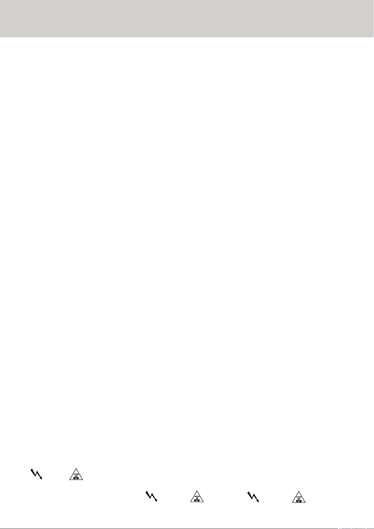
Figure 1: Comparison of a 4 m array’s near-to-far field
transition in theory and practice
1 Line Array Approaches
in Recent Years
Line arrays are a fixture on the contemporary sound
reinforcement scene. The design principle has its
origins in the stacks of cone loudspeakers that were
popular in the '70s.
Some 20 years later, the coherent wave front's ingress
into the high frequency range through waveguides
and acoustical mirrors ushered in a second generation of line arrays.
Here a line source makes use of the near field's diffusion. At a certain distance, the radiated cylindrical
wave front's near field transitions into a spherical
wave front. This transition from a cylindrical to a
spherical wave is contingent upon the length of the
radiator and the radiated frequency. The following
formula by Christian Heil serves to calculate the
distance at which this transition occurs:
H in meters, f in kHz
The answer is quite simple in view of the molecular
structure of air. Air molecules offer frictional resistance, impeding the sound wave's diffusion.
Some sound molecules drift outwards when the
wave's impact excites inert molecules at its fringes.
The cylindrical wave front's keen edges are smoothed
by degrees, gradually transforming the cylindrical
wave into a spherical wave front.
In mathematical terms, this can be described as
a sound vector pointing slightly outward at its
fringes. Because the velocity of propagation remains
constant, the cylindrical wave slowly tran-sition into
a spherical wave.
Technical literature describes the molecular frictional
resistance of air as atmospheric absorption of sound,
which increases exponentially as the frequency rises.
Accordingly, frictional resistance is greater at higher
frequencies, meaning that at higher frequencies,
the transition described occurs at a closer distance
(or smaller ratio).
Similar effects have been observed in analog technology where a square signal is smoothed by a
low-pass filter. It can be said that at some point
the signal regains a sine-like form.
Fig. 2 a: Continuous line source
Fig. 2 b: Gap due to curving
Mark Ureda, in turn, proposed a somewhat different formula for calculating the ratio between the
near and far fields:
l in meters, f in Hz
However, when these formulae are charted in a
graphical comparison, it is evident that their results
are quite similar.
Though in general it would appear that all aspects
of modern line arrays have been described ex-haustively, practical applications reveal some deficiencies.
According to the aforementioned formulae, at a frequency of 16 kHz the near field of a line array with
the length of 4 m extends out to 380 m!
Anyone who has heard a line array of comparable
size perform is sure to confirm that this great a
range cannot be attained in a real-world scenario.
The fact is that these values must be scaled down
substantially (see Fig. 1). Consequently, the aforementioned formulae for a continuous line source
are more theoretical in nature.
Values that are possible in theory are again reduced
in practice because the line source is not in fact
continuous in the high frequency range; instead,
it is composed of individual segments. Even with
the most painstaking effort, it is impossible to prevent
interference with or drop-outs of the continuous line
source in practical applications because housings
and edge diffraction inevitably cause some interference.
Furthermore, in theory this continuous line source
would always be linear! However, gaps are created
in the air when an array is curved, tearing the line
source apart and further reducing the range.
In order to preclude the phenomenon of gaps created
by curving, a line array would have to consist of very
many individual elements (N=>00), which unfortunately is practically infeasible (see Fig. 2 a, 2 b).
An effort to take these deficiencies into account led
to a next generation line array, with the following
section examines.
Consequently, all the aforementioned formulae
concerning a continuous line source are purely
theoretical nature and must be qualified considerably in practical applications.
Why these differences between theory and practice,
and why does a cylindrical wave transition into a
spherical wave front rather than diffuse infinitely?
Page 7
COHEDRA® Technology
7
2 Development Objectives
2.1 High Frequency Range
The tweeter should radiate coherent waves throughout its frequency range. In addition, the phase position should be fine-tuned and tweaked to harmonize
with the midrange woofer to afford the highest
possible fidelity and natural response. In order to
ensure uniform dispersion of sound, the driver should
channel into a constant directivity horn that is
free of undesirable diffractive effects and does not
adulterate the sonic image.
2.2 Middle Frequency Range
Midrange frequencies should be projected in short,
dry bursts. Homogenous dynamic response appropriate to the tweeter is also desirable. Like the
tweeter's time-aligned frequencies, the midrange
woofer should be time-aligned for all frequencies
that it transmits. To fulfill a line array system's
handling potential, its mid/high unit should satisfy
the requirements of full-range voice applications.
2.3 Low Frequency Range
Low frequency energy should be dispersed into the
air faster and with the greatest possible dynamic
precision. A bass array with a large near field is
desirable. Subwoofers should be designed for versatility, affording greatest flexibility in setup options.
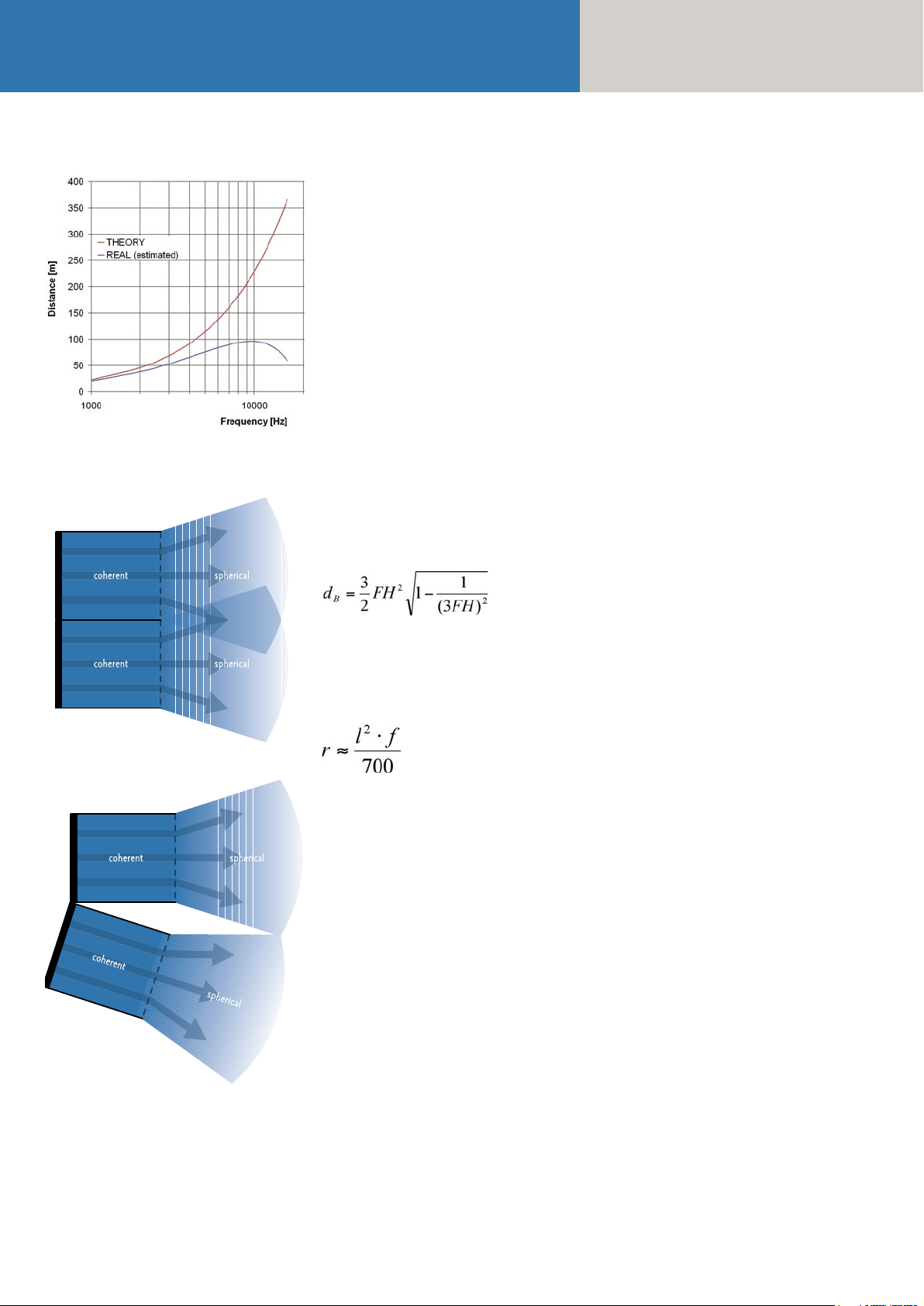
3 Emphasized Radiation
Technology™
So how does one go about developing a next
generation line array? Emphasis is a familiar concept
in analog technology. What this means is that those
signal components that will later be dampened are
emphasized first. To apply this concept to wave
fronts, the fringes that are later smoothed must
be emphasized first. In this case, emphasis means
simply that the edge areas are projected earlier in
time, forming a slightly inward curving wave front
whose sound vectors face slightly inwards
(see Figure 3 a).
ends of every element's wave fronts are reshaped in
the same way. A line source forms again at a certain
distance (Fig. 3.1). Emphasized Radiation technology is thus able to sustain the even wave for a longer
period, thereby significantly extending the line
array's near field in the high frequency range!
To clarify the influence of the gap, the following examines the directivity of an ideal line array without
gaps and of a line array with evenly and unevenly
distributed gaps. Basically, it can be said that every
line source is always accompanied by undesirable
side lobes. Like interference, these side lobes are
clearly audible artifacts and therefore extremely undesirable. Unfortunately, they cannot be avoided altogether, so it is important to minimize their level.
Figure 5 shows that an unevenly distributed gap
(pink) causes more irregular and more pronounced
side lobes. Without a gap (red) present, the array's
first side lobe occurs at a level of -13.58 dB. When
distributed across four elements of the same size
(blue) with the gap accounting for 18 percent of
the surface area, the level increases to -12.83 dB.
If these gaps are distributed unevenly, the level of
the first side lobe rises to -11.93 dB. This is nearly 1
dB higher than the level attained with the unevenly
distributed gap alone!
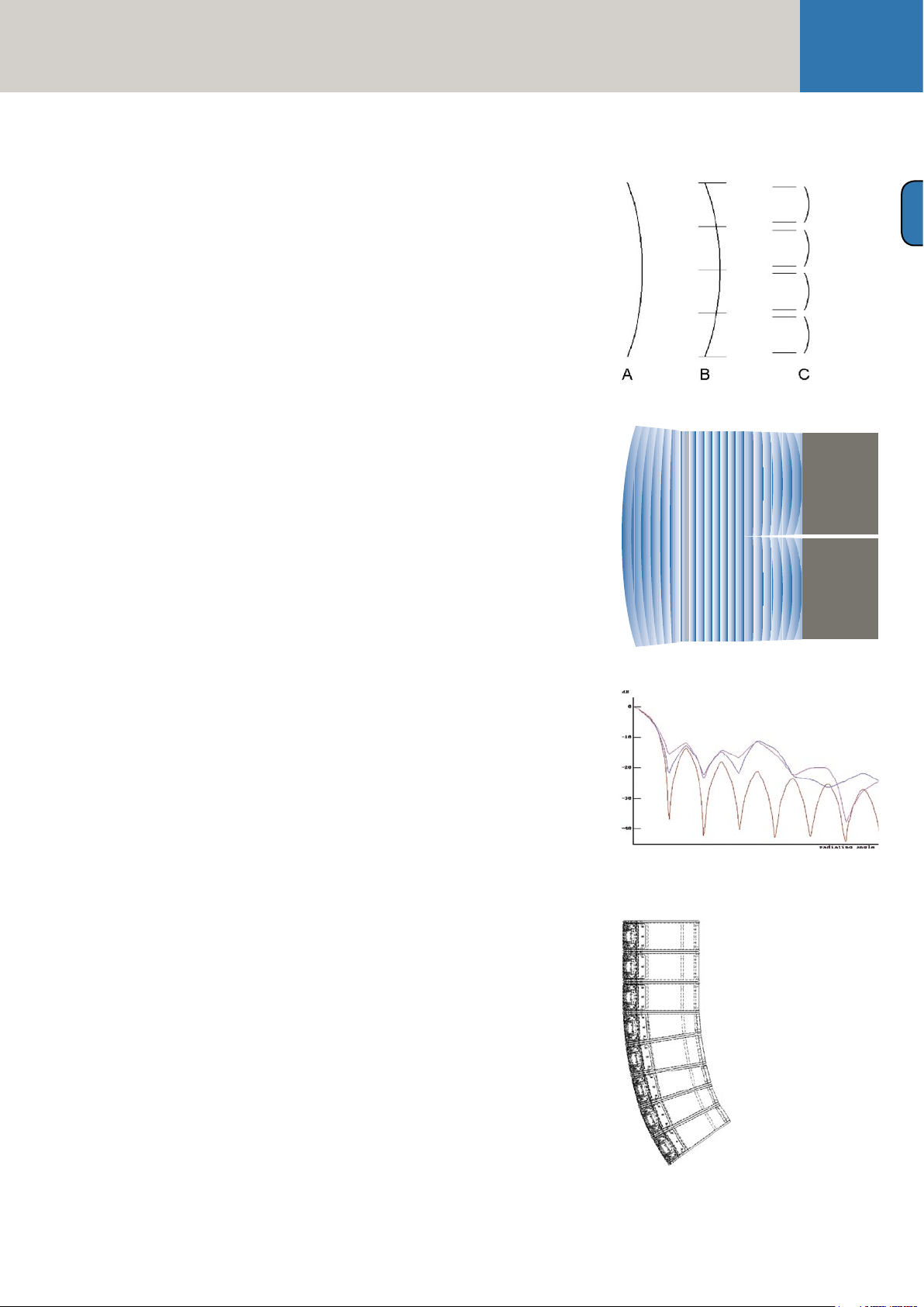
It is very important that the gap is distributed as
uniformly as possible across the full breadth of the
radiator. COHEDRA® achieves this by using two
different housing shapes for the mid/high array,
affording the greatest possible uniformity in gap
size for all typical configurations. This also ensures
minimum variation in gap size for the J array, a
configuration that today is used almost exclusively.
A
Figure 3 a-c: Emphasized radiation in a line array
Figure 3.1: Extended line Array near-field
Figure 4: Effect without gap (red), with evenly distributed
gap (blue), and with unevenly distributed gap (pink)
When applied to a continuous line source, this
creates a waveform as shown Fig. 3 b. Because
large line arrays typically consist of several identical
segments, a dedicated speaker would be required
for each segment. Apart from the fact that such a
continuous line source would be hard to implement,
practical applications also mandate great flexibility,
rendering such a concept in-feasible.
For these reasons, every element is curved slightly.
(Fig. 3 c). Due to the gaps between the elements,
which as stated above are inevitable anyway, both
Figure 5: Typical J shape
Page 8
Manual
COHEDRA® & COHEDRA® Compact
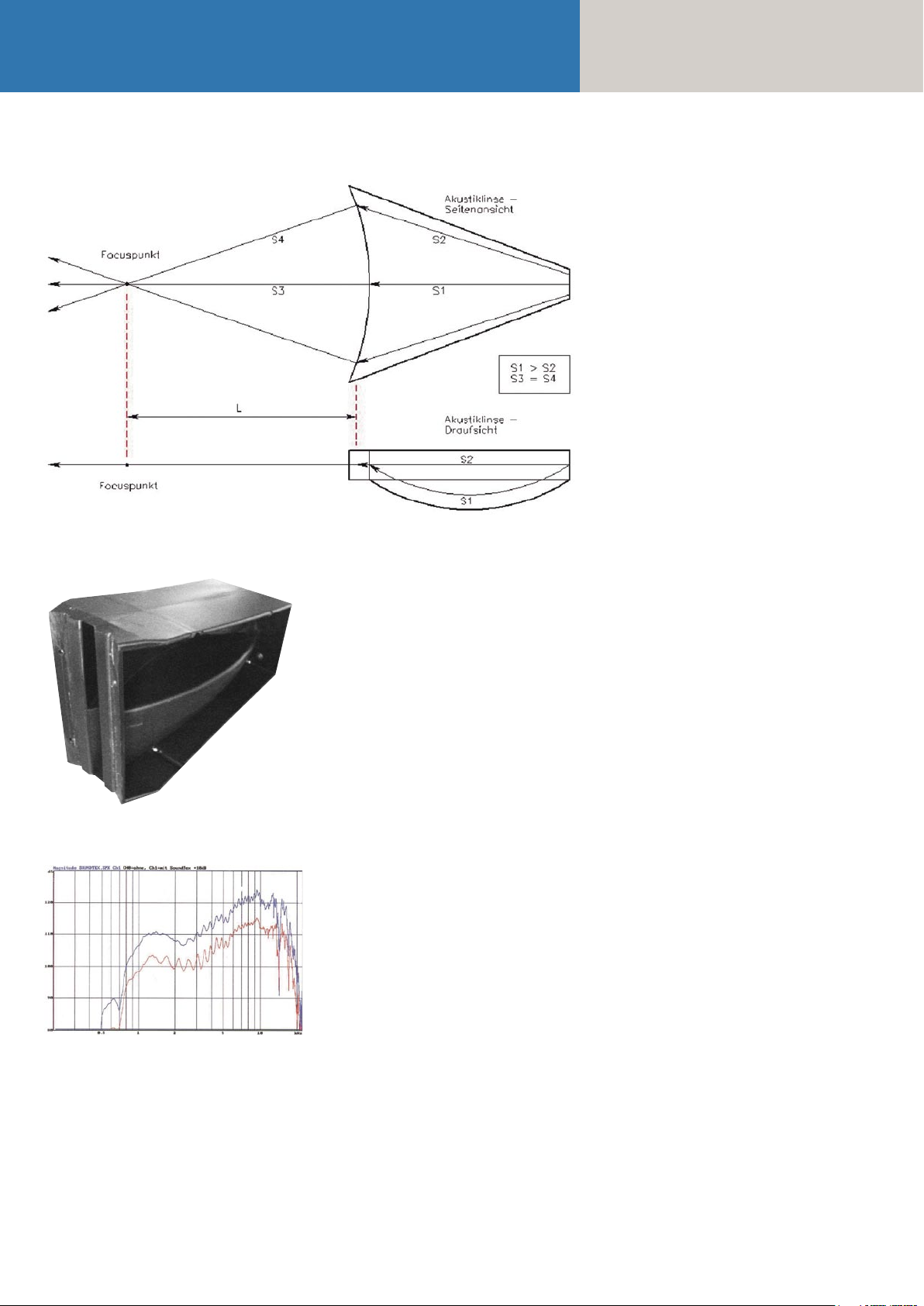
Figure 6: The COHEDRA® acoustic lens’ mode of operation
3.1 The High Frequency
Wave Front
A specially developed and patented acoustic lens
serves to curve the wave front. It transforms the
spherical wave emitted by the high frequency driver
into an inward curving wave front.
To shape a curved wave front, the sound wave's
inner components are re-channeled into a bisected,
centrically symmetrical array. In contrast to an axial
symmetrical array, a centrically symmetrical array
has the advantages of lower manufacturing tolerances. What's more the subdivided cavity enables
fewer standing waves, thereby reducing interference.
Typically, these constructions are relatively long
to minimize the differences between S1 and S2.
However, acoustically speaking this creates something approaching an organ pipe. The only remedy
is to connect a very large horn, an option that for
technical reasons is often infeasible. A covering
with a porous absorber is another possibility. Designed to reduce the velocity jump in sound particle
acceleration, this covering must be acoustically very
transparent.
Figure 7: The COHEDRA® acoustic lens
Figure 8: Effect of the synthetic fiber fleece
To this end, COHEDRA® employs a special synthetic
fiber fleece with defined aerodynamic resistance.
This absorber reduces the velocity jump in sound
particle acceleration, thereby helping considerably
to homogenize frequency response. Figure 8 illustrates the fleece's effect. The red curve shows
amplitude without fleece, the blue curve with
fleece. The two curves are depicted in staggered
formation only for the purpose of illustration.
Page 9
COHEDRA® Technology
9
3.2 Midrange
A frequently occurring and often cited drawback
of line arrays is their sensitivity to wind. A look at
the construction of conventional line arrays reveals
that many do without a CD horn. Therefore, the
HF pattern of throw is increasingly constricted. It
is not uncommon for a radiation angle of an HF
unit nominally rated for 120° to come to just 50° at 16
kHz. A light wind from the side audibly carries away
the HF signal. In the case of conventional speaker
clusters this is not so significant because several
HF units are arrayed horizontally and these pick
up the slack to provide HF sound reinforcement.
In a line array, however, it is always just one HF unit
that is arrayed horizontally to target a predetermined
audience area!
A special speaker cover is located in front of the two
8" midrange speakers. Designed to shape the horn
contour with CD characteristic in front of the acoustic
lens, it is free of undesirable diffractive effects and
does not adulterate the sonic image. It does not
constrict the HF range and ensures greater stability
in the face of gusts of wind.
The sound of the 8" speakers emanates through
slots on the top and bottom of this cover. This
enhances the dynamic balance in the range of 130
to 900 Hz.
In addition, the cover creates a compression chamber
that behaves like an acoustical filter, suppressing
frequencies that lie above the rendered frequency
range. Rather than being dissipated, the energy is
displaced to a lower frequency range, thereby substantially increasing efficiency in the rendered frequency range! Because the speaker now acts against
a limited volume of air, distortion decreases so that
very high levels can be achieved with little distortion,
much like in a horn.
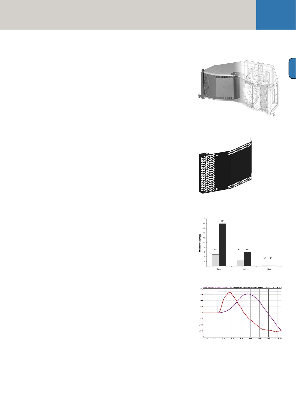
3.3 The Subwoofer-
Truest Dynamic Response
A great drawback of conventional woofers is the
considerable moving mass of the speaker (generally, 18"). As a result, low frequency reproduction is
marred by dynamic distortion.
There is only way to satisfy the desire for the driest,
cleanest possible low end response; that is to achieve
the best possible impulse behavior. By definition,
this requires a smaller speaker membrane with less
moving mass. The answer is a special 10" woofer.
Compared below is a typical 18"+12"+2" combination and the COHEDRA® solution. Notably, the
speaker membrane's moving mass in the low and
middle frequency ranges is clearly reduced.
Superior impulse behavior is also evident in the 10"
speaker's transient response. In comparison with
an 18" woofer, the membrane of the 10" woofer is
able to move much faster because its transients are
shorter.
The blue curve shows the in theory ideal response
and the red curve indicates the 10" speaker's transient
response. The purple curve shows the transient response of the 18" woofer. Measurements were taken
using a second order, 130Hz low-pass filter.
New filtering approaches were necessary to make
the most of the 10" woofer's capabilities, which is
why the housing also sports some special design
features. In combination with the bass reflex channel, the baffle boards form a horn, resulting in a
higher level in the low frequency range. The long,
lean chassis supports the formation of bass arrays
as well as ground coupling. In addition, extremely
compact clusters can be configured by setting enclosures on end. Because the loudspeaker chassis is
tropic-proof, the enclosure can do without a leveldampening front covering.
A
Figure 9: Front view of the COHEDRA®
CDR 208 mid/high enclosure
Figure 10: 8" speaker cover serving as a CD horn and
part of the compression chambe
Figure 11: Comparison of moving masses
Figure 12: Impulse response: ideal (blue), 10" (red), 18" (purple)
Page 10

Manual
COHEDRA® & COHEDRA® Compact
Chapter B
The COHEDRA® Loudspeakers
1 COHEDRA® Loudspeakers ..................... 11
1.1 CDR 208 S and CDR 208 T Mid/High
Enclosures ................................................ 11
1.2 CDR 210 Sub Subwoofer ......................... 12
1.3 CDR 210 F Sub Subwoofer .......................13
Index of Figures:
Fig. 1: Cohedra CDR 208 T ..................................11
Fig. 2: Cohedra CDR 208 S ..................................11
Fig. 3: Cohedra CDR 210 Sub ............................. 12
Fig. 4: Cohedra CDR 210 F Sub ...........................13
Page 11
The COHEDRA® Loudspeakers
11
1 COHEDRA®
Loudspeakers
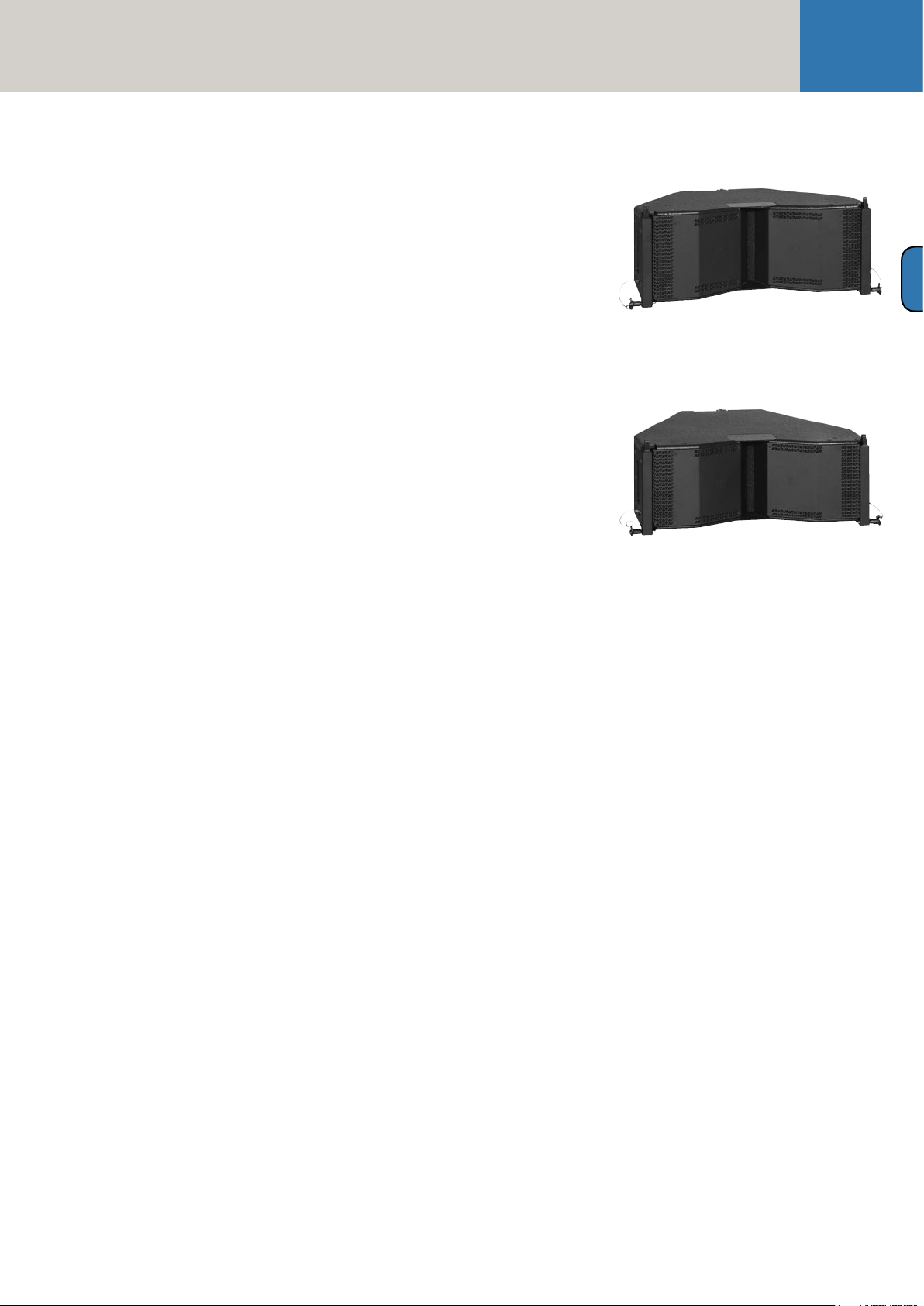
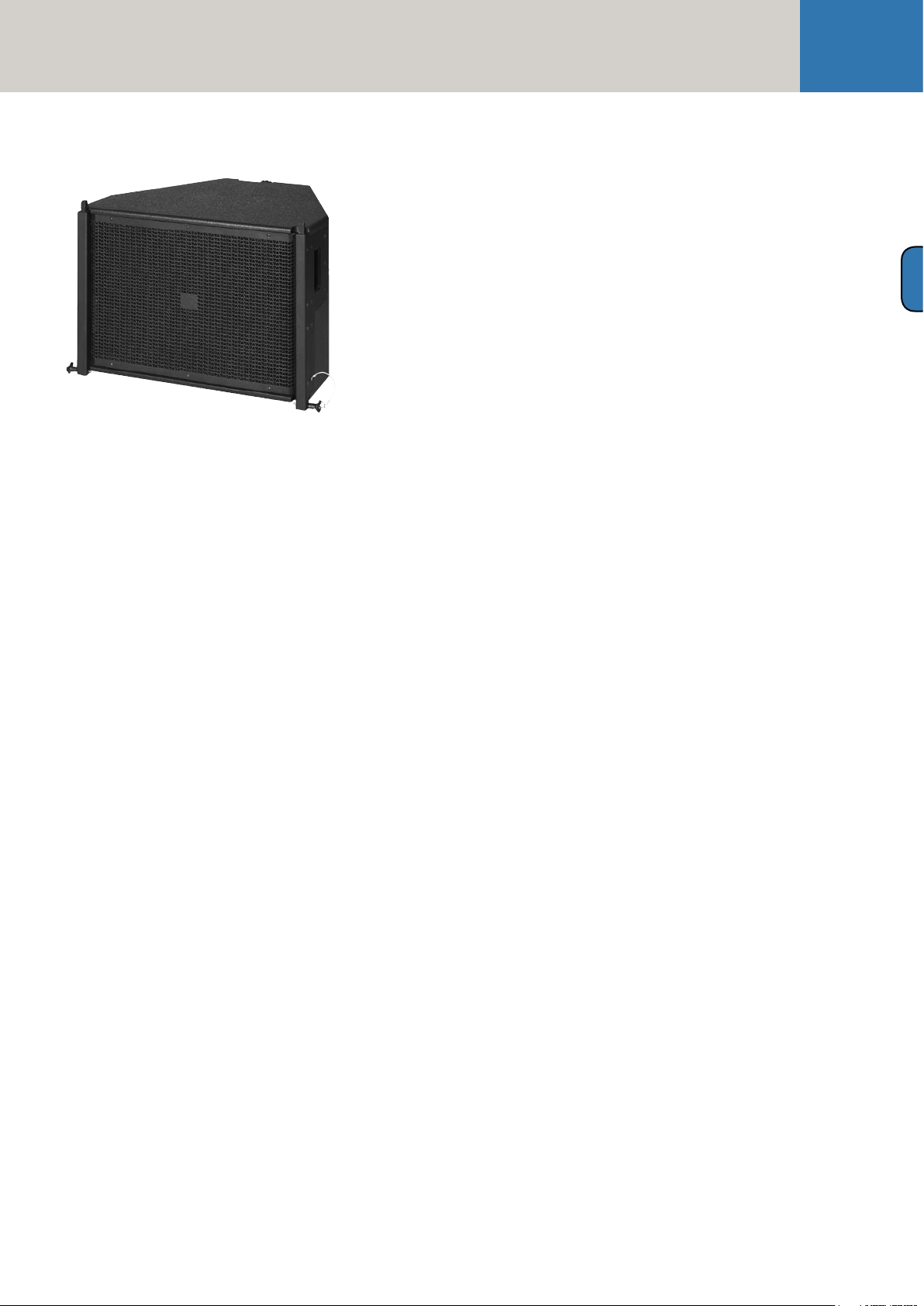
1.1 CDR 208 S and CDR 208 T
Mid/High Enclosures
Design and Construction of the Mid/High Enclosures
Two types of housings are available, the purpose of
the different design being to optimize the typical "J"
form of mid/high arrays. The CDR 208 S is housed
in a straight rather than slanted cabinet. The CDR
208 T (T is short of trapezoidal) enclosure's top
and bottom are slanted at 4.5° angles, a design that
enables the configuration of sharply curving down-fills.
CDR 208 S and CDR 208 T enclosures are made of
19 mm, 13-ply birch plywood and coated with waterrepellent, black acrylic enamel. The baffle board
cover consists of a metal grille that also serves as
a compression chamber and a horn channel for
the 1.4" driver.
The CDR 208 S and CDR 208 T weigh 30 kg.
They are 65 cm wide, 25.5 and 24 cm high, respectively,
and 60 cm deep (including rigging attachments).
Two slot grips have been routed into the side panels
for easy transport and set-up.
Connections
The connector panel on the rear of CDR 208 S (T)
enclosures is recessed to protect the ports from
harm. On these enclosures, you'll find two Speakon
NL 4 connectors. Both ports' four pins are wired in
parallel. Pin assignments are:
pin 1+ = mid/high +, 1- = mid/high -,
2+ = sub +, 2- = sub 2-.
CDR 208 S and CDR 208 T Enclosures'
Technical Data
Power handling (RMS): 500 watts
Power handling (program): 1,000 watts
Impedance: 8 ohms
Chassis: 2x 8" / 1.4" B&C
Frequency range (±3 dB): 88 Hz to 16 kHz
Frequency range (-10 dB): 75 Hz to 19 kHz
SPL (1W / 1m, half-space): 108 dB
SPL (maximum, half-space) *): 139 dB @ 10 % THD
SPL (peak, half-space) *): 146 dB
Crossover frequency: 800 Hz
Horizontal dispersion: 80°, constant directivity
Vertical dispersion: Depends on the no. of stacked
enclosures and curving configuration
B
Figure 1: Cohedra CDR 208 T
Figure 2: Cohedra CDR 208 S
Serving to fly the enclosures are fully integrated
rigging attachments comprising four quick-release
pins and three rigging connectors, two mounted on
the sides and one in the rear.
Electrical and Acoustical Data
CDR 208 S (T) enclosures feature two horn-loaded
8" cone chassis speakers and a 1.4" B&C high frequency driver with a front-mounted acoustic lens in
a CD horn configuration. Aligned in a tri-axial array,
the drivers are addressed via an internal passive
crossover with a separating frequency of 800 hertz.
CDR 208 S (T) enclosures' nominal electrical
power-handling capacity is 500 watts RMS at 8 ohms
impedance. They produce a sound pressure level of
108 dB (1W@1m), measured under half-space conditions. Maximum SPL measured under the same
conditions at a distance of one meter is 139 dB
at 10% THD.
The CDR 208 S (T) enclosures' horizontal dispersion
pattern is 80°. Frequency response ranges from
88 Hz to 16 kHz (±3 dB). The CDR 208 S (T) enclosures are thus able to provide sound reinforcement
public address applications calling speech only
without requiring a subwoofer.
Connections
Ports: 2 Speakon NL 4 ports, wired in parallel
Pin assignments: 1+ = mid/high +, 1- = mid/high,
2+ = sub +, 2- = sub 2-
Housing
Material: 19-mm, 13-ply birch plywood
Coating: Black acrylic enamel
Handles: Two slot grips on the sides
Rigging hardware: Integrated side and rear rigging
attachments with quick-release pins.
Weight:
CDR 208 T 30 kg 66 lbs.
CDR 208 S 30 kg 66 lbs.
Dimensions (W x H x D):
CDR 208 T: 65 x 25.5 x 60 [cm]
25 10/16" x 10 1/16" x 23 10/16" [inch]
CDR 208 S: 65 x 24 x 60 [cm]
25 10/16" x 9 8/16" x 23 10/16" [inch]
*) Specifications refer to a cluster of four Cohedra
components.
Page 12
Manual
COHEDRA® & COHEDRA® Compact
Figure 3: Cohedra CDR 210 Sub
1.2 CDR 210 Sub Subwoofer
Design and Construction of the Subwoofer
The CDR 210 Sub enclosure is made of 19 mm,
13-ply birch plywood and coated with water-repellent, black acrylic enamel. The baffle board cover
consists of a metal grille.
The CDR 210 Sub weighs 33 kg.
It is 110 cm wide, 32 high and 40 cm deep.
Two slot grips have been routed into the side panels
for easy transport and set-up.
Electrical and Acoustical Data
The CDR 210 Sub enclosure features two 10" woofers.
The loudspeakers are treated with a special coating
protecting them against dirt and moisture.
The CDR 210 Sub enclosure's nominal electrical
power-handling capacity is 600 watts RMS at 8 ohms
impedance. It produces a sound pressure level of
104 dB (1W@1m), measured under half-space conditions. Maximum SPL measured under the same
conditions at a distance of one meter is 139 dB
at 10% THD. The frequency response of the
CDR 210 Sub ranges from 47Hz to fx (± dB).
Connections
The connector panel on the rear of the CDR 210
Sub enclosure is recessed to protect the ports from
harm. On this enclosure, you'll find two Speakon
NL 4 connectors. Both ports' four pins are wired
in parallel. Pin assignments are:
pin 1+ = mid/high +, 1- = mid/high -,
2+ = sub +, 2- = sub 2-.
The Cohedra CDR 210 Sub Subwoofer's
Technical Data
Power handling (RMS): 600 watts
Power handling (program): 1200 watts
Impedance: 8 ohms
Chassis: 2x 10"
Frequency range (±3 dB): 47 Hz to fx
Frequency range (-10 dB): 39 Hz to f
SPL (1W / 1m, half-space): 104 dB
SPL (maximum, half-space) *): 139 dB @ 10% THD
SPL (peak, half-space) *): 142 dB
Connections
Ports: 2 Speakon NL 4 ports, wired in parallel
Pin assignments: 1+ = mid/high +, 1- = mid/high -,
2+ = sub +, 2- = sub 2-
Housing
Material: 19-mm, 13-ply birch plywood
Coating: Black acrylic enamel
Handles: Two slot grips on the sides
Weight:
33 kg / 72.6 lbs
Dimensions (W x H x D):
110 cm x 32 cm x 40 cm
43 2/16" x 12 4/16" x 15 5/16"
*) Specifications refer to a cluster of four
COHEDRA® components.
x
Page 13
The COHEDRA® Loudspeakers
Figure 4: Cohedra CDR 210 F Sub
13
B
1.3 The CDR 210 F Sub Subwoofer
Design and Construction of the Subwoofer
The CDR 210 F Sub's enclosure is made of 19 mm,
13-ply birch plywood and coated with water-repellent, black acrylic enamel. The baffle board cover
consists of a metal grille.
The CDR 210 F Sub weighs 40 kg. It is 65.5 cm
wide, 48 cm high and 60 cm deep. Two slot grips
have been routed into the side panels for easy
transport and set-up.
Electrical and Acoustical Data
The CDR 210 F Sub enclosure features two
10" woofers. The enclosures are provided with
a special coating that protects them against dirt
and water.
The CDR 210 F Sub enclosure's nominal electrical
power-handling capacity is 600 watts RMS at 8 ohms
impedance. It produces a sound pressure level
of 104 dB (1W@1m), measured under half-space
conditions. Maximum SPL measured under the same
conditions at a distance of one meter is 139 dB at
10% THD. Frequency response ranges from 47 Hz
to fx (± dB).
The CDR 210 F Sub Enclosure's Technical Data
Power handling (RMS): 600 watts
Power handling (program): 1200 watts
Frequency range (±3 dB): 47 Hz to fx
Frequency range (-10 dB): 39 Hz to fx
SPL (1W / 1m, half-space): 104 dB
SPL (maximum, half-space) *): 139 dB @ 10% THD
SPL (peak, half-space) *): 142 dB
Impedance: 8 ohms
Chassis: 2 x 10"
Connections
Ports: 2 Speakon NL 4 ports, wired in parallel
Pin assignments: + = mid/high +, 1- = mid/high -,
2+ = sub +, 2- = sub 2- 2-
Housing
Material: 19-mm, 13-ply birch plywood
Coating: Black acrylic enamel
Handles: Two slot grips on the sides
Weight: 40 kg/ 88 lbs.
Dimensions (W x H x D): 65.5 cm x 48.2 cm x 60 cm
25 3/4" x 20" x 23 5/8"
*) Measured using four 4 CDR 210 F Sub enclosures.
Connections
The connector panel on the rear of the CDR 210 F Sub
is recessed to protect the ports from harm. On these
enclosures, you'll find two Speakon NL 4 connectors.
Both ports' four pins are wired in parallel.
Pin assignments are pin 1+ = mid/high +,
1- = mid/high -, 2+ = sub +, 2- = sub 2-.
Page 14

Manual
COHEDRA® & COHEDRA® Compact
Chapter B 1
The COHEDRA® Compact Loudspeakers
1 COHEDRA® Compact Enclosures . . . . . . . . 15
1.1 The CDR 108 C Mid/High Unit 15
1.2 The Subwoofer CDR 210 C 16
Index of Figures:
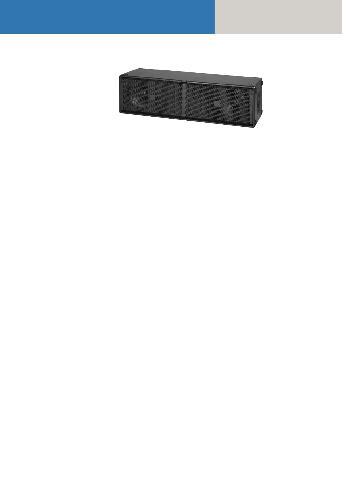
Figure 1: Cohedra® Compact CDR 108 C 15
Figure 2: Cohedra® Compact CDR 210 C 16
Page 15
The COHEDRA® Compact Loudspeakers
15
1 COHEDRA® Compact
Enclosures
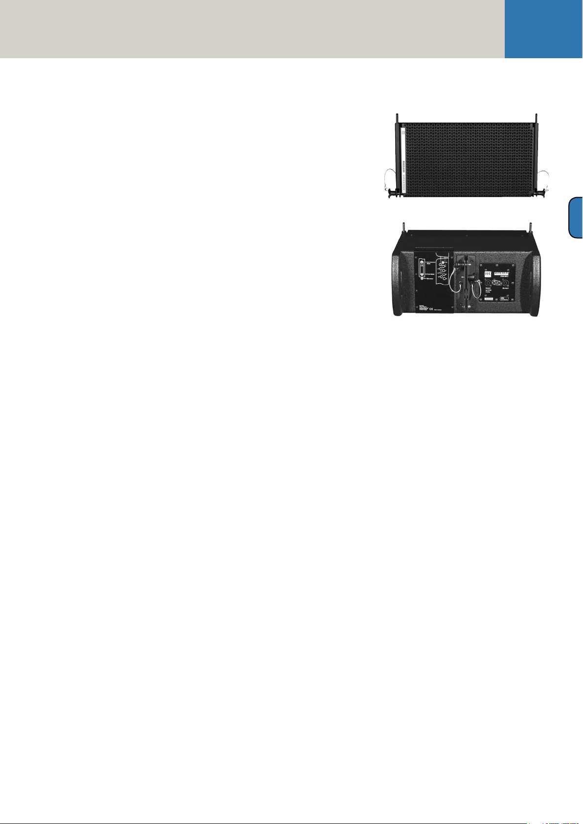
1.1 The CDR 108 C Mid/High Unit
Design and Construction
The CDR 108 C Mid/High unit’s top and bottom
panels are sloped at an angle of 4.5°. Made of 19 mm,
13-ply birch plywood, the enclosure is coated with
water-repellent, black acrylic enamel. For the purpose
of curving the array, your choices of angles (or splay)
are 0°, 1.5°, 3°, 4.5°, 6°, 7.5° and 9°. The baffle board
cover consists of a metal grille; located behind it is
a compression chamber for the 8" speaker and a
CD horn equipped with an acoustical lens for the
two 1" drivers.
The CDR 108 C weighs 17.9 kg. It is 50 cm wide, 26 cm
high and 32.5 cm deep (including rigging attachments).
Two grips on the side panels facilitate transport and
set-up.
Serving to fly the mid/high units are fully integrated
rigging attachments comprising four quick-release
pins and three rigging connectors, two mounted on
the sides and one in the rear.
Electrical and Acoustical Data
The CDR 108 C enclosure is loaded with an 8" cone
chassis speaker and two 1" B&C high frequency drivers
with a front-mounted acoustical lens in a CD horn
configuration. The drivers are addressed via an
internal passive crossover with a separating frequency
of 800 hertz.
The CDR 108 C enclosure’s nominal electrical power-handling capacity is 250 watts RMS at 16 ohms
impedance. It produces a sound pressure level
of 107 dB (1W@1m), measured under half-space
conditions. Maximum SPL measured under the
same conditions at a distance of one meter is
136 dB at 10% THD.
The CDR 108 C Enclosures’ Technical Data
Nominal power handling :
250 watts RMS, 500 watts program
Frequency range: ± 3 dB: 88 Hz – 19 kHz
SPL, 1W @ 1m*: 107 dB
SPL, max. SPL @ 1m*: 136 dB @ 10% THD**
Impedance: 16 ohms
Woofer/midrange speaker: 1x 8" with compression
chamber
High-frequency driver: 2x 1" with COHEDRA®
Acoustic Lens
Horn: 100° CD horn
Crossover frequency: 800 Hz, 12 dB/ octave
Ports: Speakon® NL 4 connectors
Pin assignments: 1+ = mid/ high +, 1- = mid/ high -,
2+ = sub +, 2- = sub 2-
Housing
Material: 15-mm (5/8"), 13-ply birch plywood
Coating: Black acrylic enamel
Front grille: Metal
Rigging hardware: Integrated rigging attachments
Variable splay for curving arrays: 0°, 1.5°, 3°, 4.5°,
6°, 7.5°, 9°
Weight: 17.9 kg / 39.4 lbs
Dimensions (W x H x D):
50 x 26 x 32.5 cm
19-5/8" x 10-1/4" x 12-3/4"
*) SPL measured under half-space conditions
**) measured with 4 CDR 108 Cs
B 1
Figure 1: Cohedra Compact CDR 108 C
The CDR 108 radiates at a horizontal angle of 100°.
Frequency response ranges from 88 Hz to 19 kHz
(±3 dB). The enclosure is thus able to provide
speech reinforcement for public address applications without requiring a subwoofer.
Connections
The connector panel on the rear of the CDR 108 C
is recessed to protect the ports from harm. On this
enclosure, you’ll find two Speakon® NL 4 connectors. Both ports’ four pins are wired in parallel.
Pin assignments are: pin 1+ = mid/high +,
1- = mid/high -, 2+ = sub +, 2- = sub 2-.
Page 16
Manual
COHEDRA® & COHEDRA® Compact
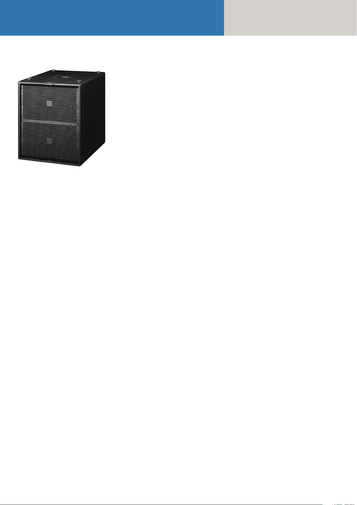
Figure 2: Cohedra Compact CDR 210 C
1.2 The Subwoofer CDR 210 C
Design and Construction of the Subwoofer
Made of 19 mm, 13-ply birch plywood, the CDR 210
C enclosure is coated with water-repellent, black
acrylic enamel. The baffle board cover consists of a
metal grille.
The CDR 210 C weighs 48 kg. It is 55 cm wide, 60
high and 63 cm deep. Two slot grips have been
routed into the top, bottom and back panels for easy
transport and set-up.
Electrical and Acoustical Data
The CDR 210 Sub enclosure is loaded with two 10"
woofers. The loudspeakers are treated with a special
coating protecting them against dirt and moisture.
The CDR 210 C enclosure’s nominal electrical
power-handling capacity is 600 watts RMS at 8
ohms impedance. It produces a sound pressure level
of 104 dB (1W@1m), measured under half-space
conditions. Maximum SPL measured under the same
conditions at a distance of one meter is 139 dB at
10% THD**. The frequency response of the CDR 210
C ranges from 47Hz to fx (± dB).
Connections
The connector panel on the rear of the CDR 210
C enclosure is recessed to protect the ports from
harm. On this enclosure, you’ll find two Speakon®
NL 4 connectors. Both ports’ four pins are wired in
parallel. Pin assignments are pin 1+ = mid/high +,
1- = mid/high -, 2+ = sub +, 2- = sub -.
The Cohedra CDR 210 C Subwoofer’s Technical Data
Power handling (RMS): 600 watts RMS,
1200 watts program
Frequency range (±3 dB): 47 Hz to fx
Frequency range (-10 dB): 39 Hz to fx
SPL, 1W @ 1m*: 104 dB
SPL, max. SPL @ 1m*): 139 dB @ 10% THD**
Impedance: 8 ohms
Woofers: 2x 10"
Connections: 2 NL 4 Speakon® ports, wired in parallel Pin assignments: 1+ = mid/ high +, 1- = mid/ high
-, 2+ = sub +, 2- = sub 2-
Housing
Material: 19-mm (3/4"), 13-ply birch plywood
Coating: Black acrylic enamel
Front grille: Metal
Handles: Four slot grips
Rigging hardware: Integrated pick points
Weight: 48 kg (105.6 lbs)
Dimensions (W x H x D): 50 cm x 60 cm x 63 cm
19 3/4" x 23 3/4" x 24 3/42
*) SPL measured under half-space conditions
**) measured with 4 CDR 210 Cs *)
Page 17

Chapter C
COHEDRA® Transport Solution
The COHEDRA® Transport Solution .................... 18
1.1 Mid/High Enclosures ..................................... 18
1.2 Subwoofers .................................................... 18
1.3 Dimensions and Weights of the Cases
and Bass Bin Dollies ...................................... 19
1.4 COHEDRA® Truck Space ................................ 19
Index of Figures:
Fig. 1: COHEDRA® Mid/ High-Case ................... 18
Fig. 2: COHEDRA® Subwoofer-Dolly .................. 18
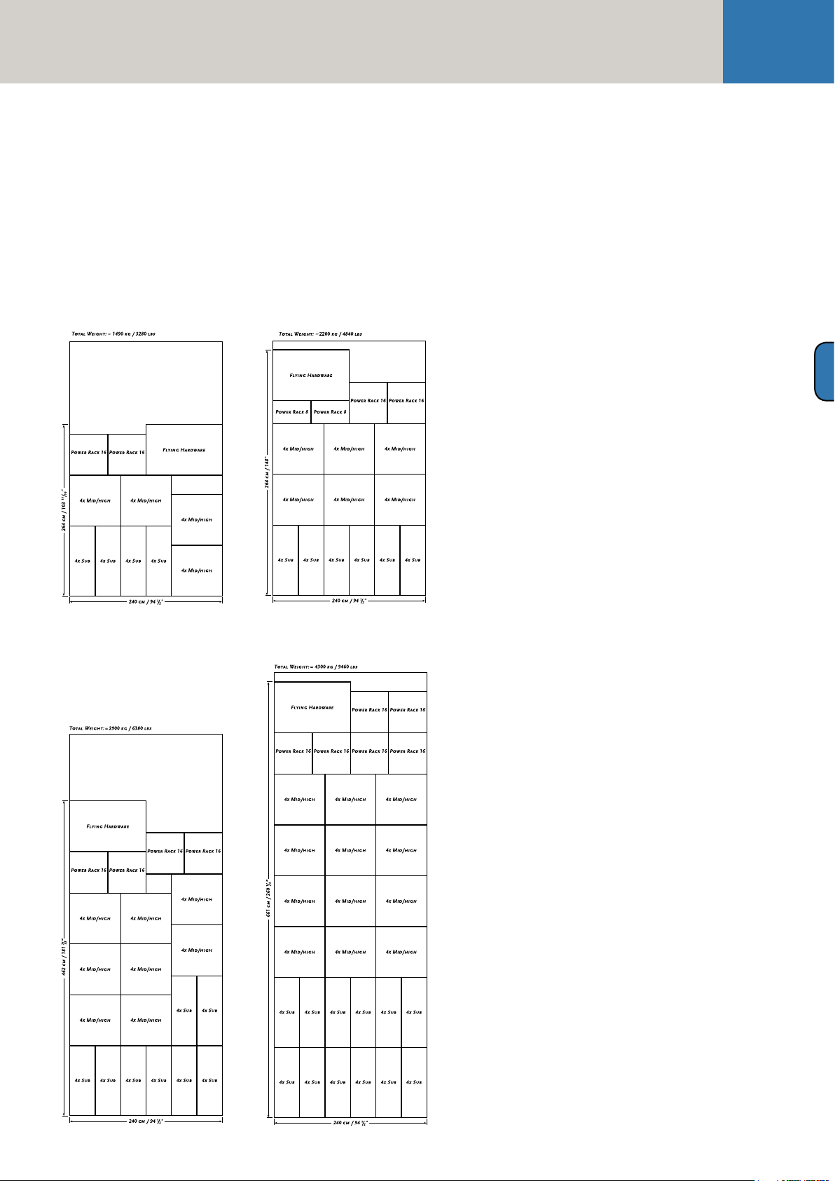
Fig. 3: 16 Mid/ High-Cabinets
and 16 Subwoofers ................................... 19
Fig. 4: 24 Mid/ High-Cabinets
and 24 Subwoofers ................................... 19
Fig. 5: 32 Mid/ High-Cabinets
and 32 Subwoofers ................................... 19
Fig. 6: 48 Mid/ High-Cabinets
and 48 Subwoofers ................................... 19
17
C
Page 18
Manual
COHEDRA® & COHEDRA® Compact
The COHEDRA®
Transport Solution
1.1 Mid/High Enclosures
A specially designed case serves to transport the
COHEDRA® CDR 208 S, CDR 208 T mid/high and
the CDR 210 F Sub enclosures.
The floor of the mid/high enclosure case is adjustable
to 0° and 4.5°. This enables you to configure the S
and T model housing as desired without having to
disassemble clusters consisting of up to four mid/
high enclosures for transport.
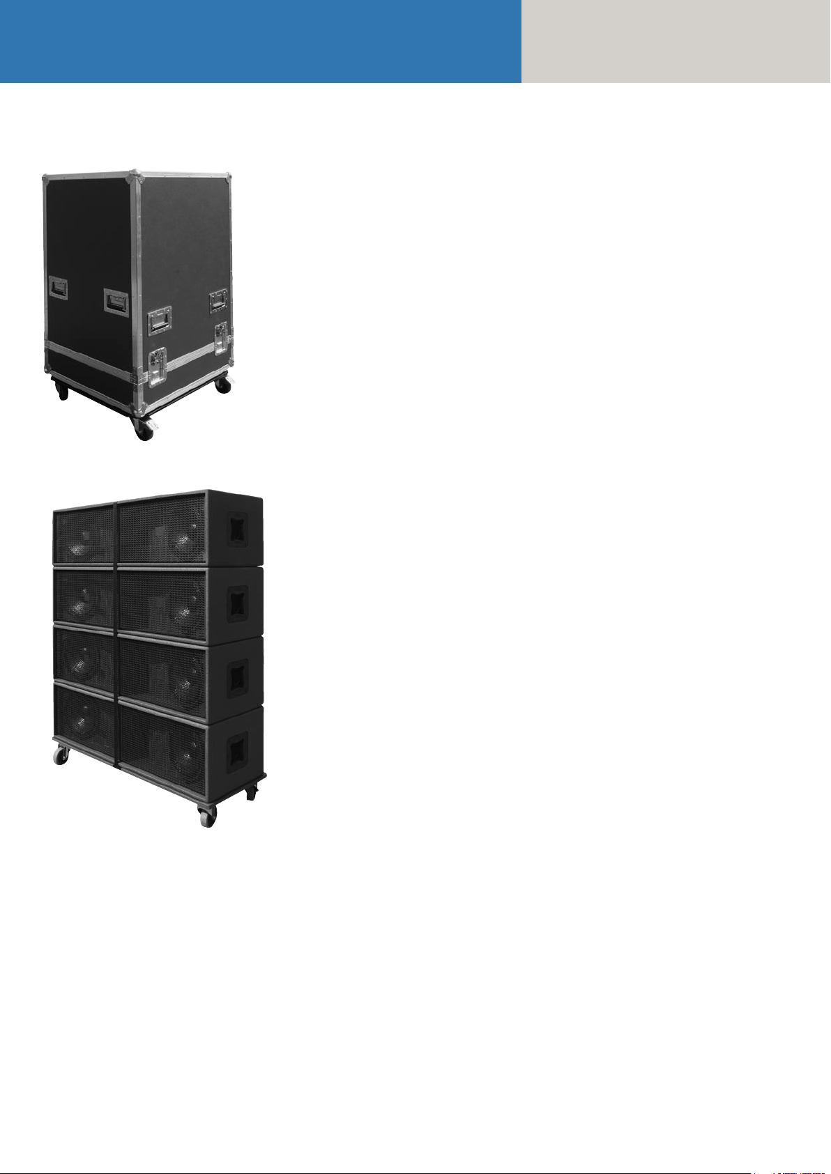
1.2 Subwoofers
Figure 1: COHEDRA® Mid/ High Case
Figure 2: COHEDRA® Subwoofer Dolly
Serving to transport subwoofers is a dolly designed
to carry four stacked subwoofers. Subwoofers are
secured to the dolly using a cargo strap.
1.3 Dimensions and Weights of
the Cases and Bass Bin Dollies:
Case for four CDR 208s or two CDR 210 F Sub:
Width: 80 cm (31 1/2")
Depth: 74 cm (29 1/8")
Height: 131 cm (51 5/8")
Weight: approx. 150 kg (330 lbs.)
Four CDR 210 Subs with dolly and strap:
Height: 148 cm (58 1/4"), casters included
Width: 40 cm (15 3/4")
Depth: 110 cm (43 1/4")
Weight: 138 kg (304 lbs.)
PR 16 (lying):
Width: 60 cm (23 5/8")
Height: 65.5 cm (25 3/4") (depth, when standing
on casters)
Depth: 95 cm (37 3/8") (height, when standing
on casters)
Weight: approx. 125 kg (275 lbs.)
PR 8 (lying):
Width: 60 cm (23 5/8")
Height: 38.5 cm (15 3/16") (depth, when standing
on casters)
Depth: 95 cm (37 3/8") (height, when standing
on casters)
Weight: approx. 65 kg (143 lbs.)
Flying Hardware Case (on casters):
Width: 120 cm (47 1/4")
Depth: 80 cm (31 1/2")
Height: 58 cm (22 3/4")
Weight: approx. 90 kg (198 lbs.)
Page 19
COHEDRA® Transport Solution
1.4 COHEDRA® Truck Space
The dimensions of COHEDRA® cases, racks and
dollies were selected specifically to make the most
of available truck space. The diagrams below offer
suggestions on how to load different COHEDRA®
systems into a truck with a width of 240 cm.
19
C
Page 20

Manual
COHEDRA® & COHEDRA® Compact
Chapter C 1
COHEDRA® Compact Transport Solution
1 COHEDRA® Compact Transport Solution . . . .21
1.1 CDR 108 C Mid/High Case . . . . . . . . . . . . . . . 21
1.2 Dimensions and Weights . . . . . . . . . . . . . . . . . 21
Index of Figures:
Fig. 1: COHEDRA® Compact Mid/High Case. . . 21
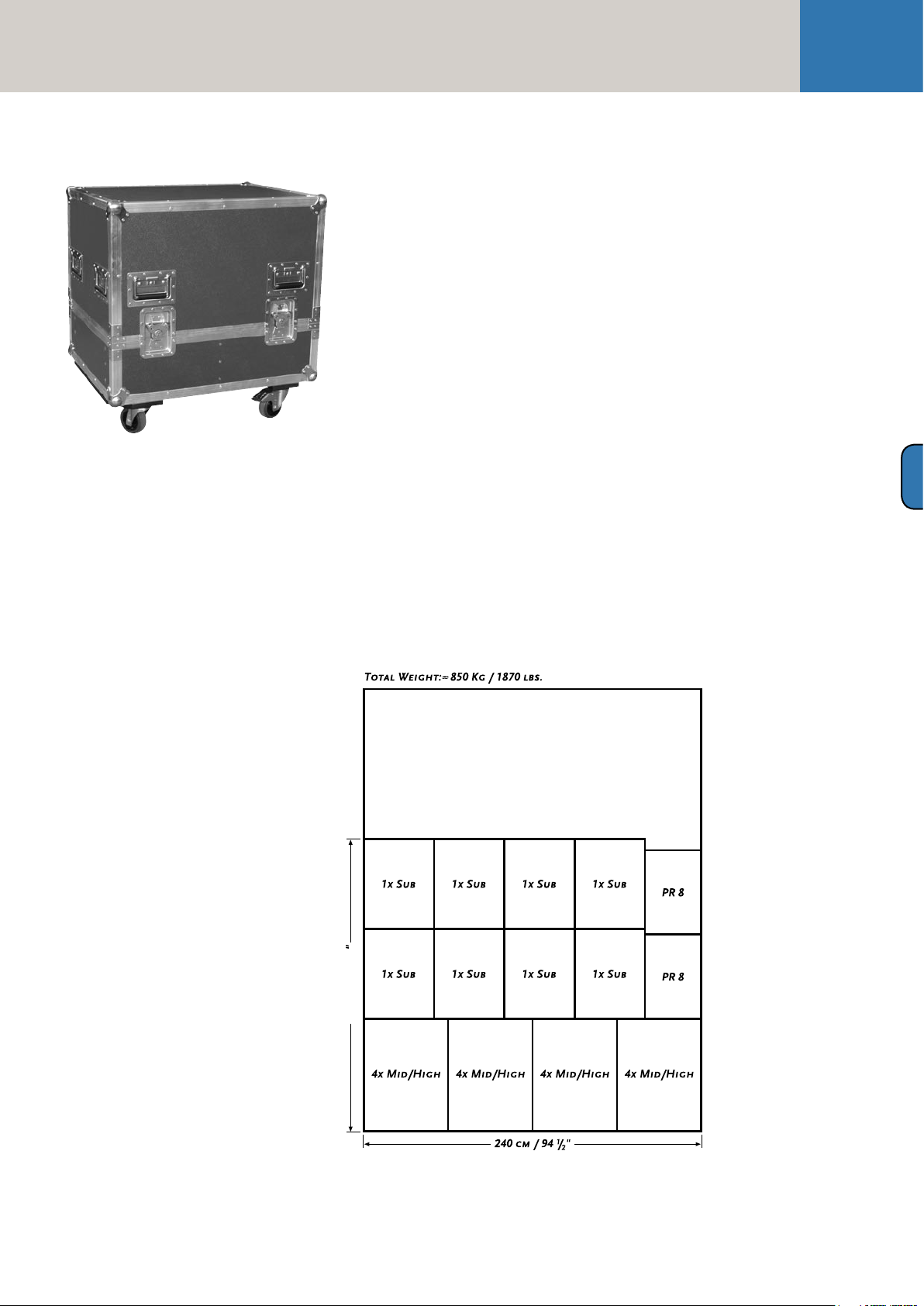
Fig. 2: 16 Mid/High enclosures and
8 Subwoofers. . . . . . . . . . . . . . . . . . . . . . . 21
Page 21
208 cm / 81
7
/
8
COHEDRA® Compact Transport Solution
21
Figure 1: COHEDRA® Compact Mid/High Case
1 COHEDRA® Compact
Transport Solution
1.1 CDR 108 C Mid/ High Case
A specially designed case serves to transport
COHEDRA® Compact CDR 108 C mid/high enclosures. One case accommodates four CDR 108 Cs
and a standard rigging frame each.
1.2 Dimensions and Weights
Case for four CDR 208 s:
Width: 80 cm/ 31 1/2"
Depth: 60 cm/ 23 5/8"
Height (standing on casters): 70 cm/ 27 1/2"
Weight (without rigging frame) : approx. 98 kg/ 215 lbs.
Weight (with rigging frame) : approx. 108 kg/ 238 lbs.
PR 16 (lying):
Width: 60 cm/ 23 5/8"
Height: 65.5 cm/ 25 3/4"
Depth (standing on casters): 95 cm/ 37 3/8"
Weight: approx. 125 kg/ 275 lbs.
PR 8 (lying):
Width: 60 cm/ 23 5/8"
Height: 38.5 cm/ 15 1/8"
Depth (standing on casters): 95 cm/ 37 3/8"
Weight: approx. 65 kg/ 143.3 lbs.
CDR 210 C:
Width: 50 cm/ 19 3/4"
Height: 60 cm/ 23 1/4"
Depth (standing on casters): 75 cm/ 29 1/2"
Weight: approx. 48 kg/ 105.6 lbs.
C 1
Page 22

Manual
COHEDRA® & COHEDRA® Compact
Chapter D
Rigging & Curving the COHEDRA® System
Rigging and Curving Mid/high Cabinets ............... 23
1 Use 26
1.1 Intended Use .................................................. 23
1.2 Unintended Use .............................................. 23
2 Warranty and Liability .................................... 23
3 Important Notes on Safety ............................. 23
3.1 Responsibilities of the Operator ..................... 23
3.2 Storage, Maintenance, Inspection and
Repair of COHEDRA® Rigging Hardware .......24
3.3 Technical Specifications of
the Rigging Hardware ..................................... 24
3.4 Maximum Permissible Number
of Flown COHEDRA® Mid/High Units ...........24
3.5 Maximum Number of Flown
COHEDRA® CDR 210 F Subwoofers ............... 25
3.6 Ground-stacked Mid/High Enclosures ........... 25
3.7 Pick Points for Flying Mid/high Enclosures .... 25
3.8 Structural Modifications of Rigging Hardware 25
3.9 Original HK AUDIO® Accessories: ................. 25
3.10 Initiation and Operation ................................. 25
4 Components of the Rigging Hardware .......... 26
5 Determining the Curving Angle between
Two COHEDRA® Mid/High Enclosures ......... 27
6 Preparations ................................................... 27
7 Mounting the Top Rigging Frame .................. 28
8 Mounting Additional Mid/High Enclosures .. 30
9 Attaching the Bottom Rigging Frame
and Raising the Mid/high Array ..................... 31
10 Ground Stacking ............................................ 32
10.1 Ground Stacking with the Stack Frame ........... 32
10.2 Ground Stackin with the Rigging Frame ......... 32
11 Setting up Subwoofers ................................... 32
11.1 Sub Array ........................................................ 32
11.2 Bass Cluster/ Stacking .....................................33
11.3 Bass Clusters in Blocks ....................................33
12 Flying CDR 210 F Subs ................................... 34
Index of Figures:
Fig. 1: 12 COHEDRA® mid/high enclosures .......26
Fig. 2: Mid/high enclosure with
integrated flight attachments .................. 26
Fig. 3: Top rigging frame .................................... 26
Fig. 4: Shackles for attaching motors, straps ..... 26
Fig. 5: Bottom rigging frame ..............................26
Fig. 6: Lashing strap for curving the array ..........26
Fig. 7: Quick-release pin .....................................26
Fig. 8: The curvature between two
COHEDRA® mid/high enclosures ........... 27
Fig. 9: Setting the curving angle on a
flown array ............................................... 27
Fig. 10: Connector component attached
on the top rigging frame for
a 0° curving angle .................................... 27
Fig. 11: Open case with four mid/high
range enclosures ...................................... 28
Fig. 12 a-g: Turning the connector component ...... 28
Fig. 13: Mounting the top rigging frame ..............28
Fig. 14: Mounting the main motor to
the top rigging frame ...............................29
Fig. 15: Setting the curving angle between
COHEDRA® mid/high enclosures ...........29
Fig. 16: Hoisting the top four
COHEDRA® mid/high enclosures ...........30
Fig. 17 Mounting additional
a - d: mid/high enclosures ................................ 30
Fig. 18: Mounting the bottom rigging frame .........31
Fig. 19: Attaching the lashing strap /
second motor between the top
and bottom rigging frames .......................31
Fig. 20: Hoisting the fully assembled
COHEDRA® mid/high array .....................31
Fig. 21: Groundstack with CDR 210 F Sub
and CDR 208 S/T ..................................... 32
Fig. 22: CDR 210 sub array ....................................33
Fig. 23: CDR 210 sub cluster .................................33
Fig. 24: CDR 210 sub cluster in blocks ................. 34
Fig. 25: Flown CDR 210 F bass array
next to mid/high array ..............................35
Fig. 26: The CDR 210 F Sub's curving angle ..........35
Fig. 27: Pin assignment of channels 1-4 ................35
Index of Tables:
Table 1: Weight of mid/high enclosures ................ 38
Table 2: Weight of CDR 210 F Sub ......................... 39
13 The SL 218 as a Bass Supplement .................. 34
14 Operating the System .................................... 34
15 Disassembling and Removing the System ..... 35
Page 23

Rigging and Curving COHEDRA® System
23
Rigging and Curving
COHEDRA® Mid/high
Cabinets
Please read these instructions carefully before you
begin setting up the system!
1 Use
1.1 Intended Use
Specifications for intended use include the following:
• When mounting mid/high range enclosures, make
sure that the load is centreed directly under the
suspension point on the rigging frame.
• The rigging frame may not be tilted more than
10% (that is, at angles greater than 6°). Note that
the specifications for intended use require you to
read and heed all of the operating instructions
and comply with inspection and maintenance
requirements.
Any use other than specified is unintended.
The manufacturer shall not be liable for damages
resulting from unintended use.
• unauthorized structural modifications performed
on rigging frames
• unauthorized modification of the parameters indicated in the operating manual
• inadequate or improper repairs
3 Important Notes
on Safety
Original COHEDRA® rigging accessories have been
certified as a complete and cohesive system by the
safety standards authority TÜV. The directions for
use of the COHEDRA® rigging system require that
it be installed in accordance with the following
specifications. Before you begin installation, ensure
that the mounting points (for example, a chain hoist)
on the stage roof or the venue's ceiling comply with
BGV-C1 accident prevention regulations and that
the safety standards authority TÜV has certified
them for the full load (see table 1). Prior to every
installation, inspect all components to ensure they
are in good operating condition, taking particular
care to confirm that all quick-release pins and hardware connectors are undamaged.
D
1.2 Unintended Use
Improper use of rigging frames and incorrect
handling of this load-carrying equipment can pose
a serious danger.
Never
• use rigging frames to exert diagonal force or tension on loads,
• use a crane to dislodge stuck or immovable loads,
• lift people,
• strike, knock or dent rigging frames,
• heat-treat or weld rigging frames,
• exceed the truss's maximum load-carrying capacity
Note that in addition to the above specifications,
the operational safety regulations of VBG 9 (the
German employers' liability insurance association
accident prevention regulations) apply.
2 Warranty and Liability
HK AUDIO® cannot be held responsible for damages due to improper use or non-compliance with
the safety specifications for setup and operation.
All warranty and liability claims for personal injury
and property damages are excluded if attributable
to one or several of the following:
• non-compliance with operating manual instructions, voiding product liability and warranty claims
• unintended use of rigging frames
• non-compliance with operating manual instructions
regarding transportation, storage, initial setup,
operation, maintenance and repair of rigging frames
The principle requirement for safe handling
and trouble-free operation of rigging frames is
a thorough understanding of the basic notes on
safety and the safety regulations.
This operating manual contains key rules on safe
handling.
3.1 Responsibilities of the Operator
As the operator, you are legally bound to allow only
those persons to work with rigging frames who are
• 16 years of age or older,
• physically and mentally able, familiar with the basic
rules of industrial safety and accident prevention,
and trained in the handling of rigging frames.
Be sure to regularly review and confirm personnel's
safety awareness.
In addition, task personnel with specific responsibilities for setting up, putting into service, operating,
maintaining, and repairing equipment. Ensure
that personnel are trained to work with the rigging
frame only under the supervision of a proficient and
experienced technician. Ensure also that defects,
flaws and other damage that could impede safety
are repaired immediately.
Page 24

Manual
COHEDRA® & COHEDRA® Compact
3.2 Storage, Maintenance,
Inspection and Repair of
COHEDRA® Rigging Hardware
Storage, temporary and long-term
When not in use store the truss indoors in a safe
place where it cannot be tipped over and is protect
from exposure to the elements.
Inspections
§ 39, VBG 9 A of the German employers' liability insurance association accident prevention regulations
requires that load-carrying equipment be inspected
by a qualified expert and possible defects be eliminated prior to initial commissioning by the recipient.
§ 40, VBG 9 A requires that load-carrying equipment be inspected at least annually for cracks.
When used in dynamic applications, equipment
must be inspected for cracks every six months.
Maintenance
You are authorized to replace easily serviceable
wearing or standard parts in accordance with the
manufacturer's instructions. Use original parts for
this purpose. If necessary, tighten screws and screwed connections.
Repair
In the event that parts of the load-carrying equipment
have been deformed, it is up to the manufacturer
to determine if they are repairable. Solely the
manufacturer is authorized to perform welding and
repair jobs on load-carrying equipment.
3.3 Technical Specifications
of the COHEDRA® Rigging
Hardware
Load-carrying capacity of standard rigging frames:
800 kg
Test load: 3,200 kg
Ambient temperature when in operation:
min. -10° C, max. + 60° C
3.4 Maximum Permissible
Number of Flown COHEDRA®
Mid/High Units
• You may fly up to 32 mid/high range enclosures in
a stacked array.
• You may fly up to 24 mid/high enclosures in a
stacked array when using the standard rigging
frame.
• If you want to fly up to 32 mid/high enclosures,
you must use the high-load rigging frame! It is
available on demand.
Warning: Flying more than 24 enclosures in a stacked array from the standard rigging frame voids
the safety standards authority TÜV's certification!
Refer to table 1 to determine flown loads. The sum
of the weights of COHEDRA® mid/high enclosures
plus the weight of the rigging frames equals the
total load.
Note: Ensure that you add the weights of chain
hoists, motors, cables and further stops to determine
total weight!
Quantity Weight [kg] Weight [lbs.]
1 30 66
2 60 132
3 90 198
4 120 264
5 150 330
6 180 396
7 210 462
8 240 528
9 270 594
10 300 660
11 330 726
12 360 792
13 390 858
14 420 924
15 450 990
16 480 1056
17 510 1122
18 540 1188
19 570 1254
20 600 1320
21 630 1386
22 660 1452
23 690 1518
24 720 1584
25 750 1650
26 780 1716
27 810 1782
28 840 1848
29 870 1914
30 900 1980
31 930 2046
32 960 2112
Top and bottom rigging frame with shackle:
30 kg/ 66 lbs.
Table 1: Weight of mid/high enclosures
Page 25

Rigging and Curving COHEDRA® System
25
3.5 Maximum Number
of Flown COHEDRA®
CDR 210 F Subwoofers
The standard rigging frame can fly up to 20 vertically
arrayed CDR 210 F Subs.
If you are using a combination of CDR 208 S/T
cabinets and CDR 210 F Sub bins on one rigging
frame, calculate the total load using both tables.
Ensure the rigging frame's maximum permissible
load is never exceeded.
Number Weight [kg] Weight [lbs.]
1 40 88
2 80 176
3 120 264
4 160 352
5 200 440
6 240 528
7 270 616
8 310 704
9 350 792
10 390 880
11 430 968
12 470 1056
13 510 1144
14 550 1232
15 590 1320
16 630 1408
17 670 1496
18 710 1584
19 750 1672
20 790 1760
3.7 Pick Points for Flying
COHEDRA® Mid/high Enclosures
Use only the top rigging frame's shackles to attach
motors, chain hoists and straps. Insert them into
the eyelets in the centre rail designed to accept
shackles!
Never use the round pole on the top rigging frame
to attach shackles or mount motors! This pole is
used only for guiding and securing cables.
Use only the bottom rigging frame to curve the array.
Clear the area immediately below arrays of people
before raising or lowering loads.
Lift and lower flown mid/high enclosures smoothly,
avoiding abrupt stops or jerky motions.
Secure the flown mid/high array in place with straps
so that it remains immovable, for example, despite
gusts of wind. Use the eyelets in the bottom rigging
frame to affix straps.
3.8 Structural Modifications of
COHEDRA® Rigging Hardware
No structural modifications may be made without
the manufacturer's permission. This also applies
to welding work performed on supporting parts.
Structural alterations require the manufacturer's
written approval. Use original replacement and
wearing parts only.
3.9 Original HK AUDIO®
Accessories
D
Table 2: Weight of the CDR 210 F Sub
3.6 Ground-stacked Mid/High
Enclosures
Ensure that the (inverted) top rigging frame is placed
securely on the ground or stage. Secure the mid/high
stack to prevent slippage!
Use original HK AUDIO® parts only (see section
4)! The safety standards authority TÜV has not
certified any other parts for use! Always install parts
in accordance with these installation instructions!
Compile and store all documents pertaining to the
system in a safe place!
3.10 Initiation and Operation
§ 39, VBG 9 A of the German employers' liability
insurance association accident prevention regulations requires that load-carrying equipment be
inspected by a qualified expert and possible defects
be eliminated prior to initial commissioning by the
recipient.
§ 41 VBG 9a requires that load-carrying equipment
be subjected to a non-routine inspection following
damage, repair work and other incidents that can
affect load-carrying capacity.
Page 26
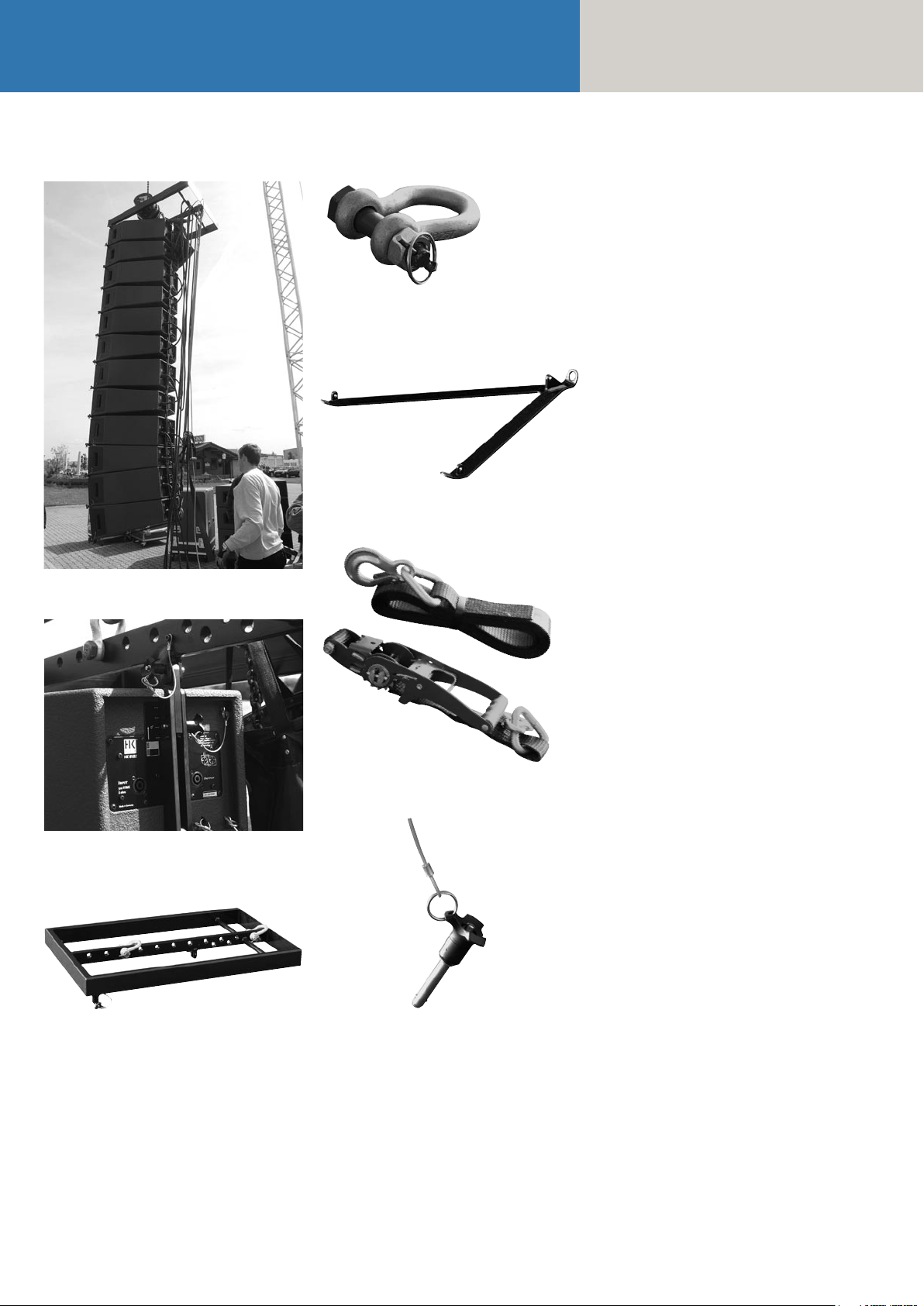
Manual
COHEDRA® & COHEDRA® Compact
Figure 4: Shackles for attaching motors, straps
Figure 5: Bottom rigging frame
4 Components of the
COHEDRA® Rigging
Hardware
COHEDRA® rigging hardware consists of the
following parts:
• a top rigging frame with three shackles for attaching
motors, lashing straps or chain hoists. The top
rigging frame also serves as the base for ground
stacks.
• a bottom rigging frame for attaching a lashing
strap, chain hoist or motor for curving the array
• a two-part lashing strap for curving arrays of up to
eight COHEDRA® mid/high enclosures
• integrated attachments on the side and back for
flying COHEDRA® mid/high enclosures
• four quick-release pins per mid/high enclosure for
connecting enclosures to the rigging frames
Figure 1: 12 COHEDRA® mid/high enclosures
Figure 2: Mid/high enclosure with integrated flight
attachments
Figure 3: Top rigging frame
Figure 6: Lashing strap for curving the array
Figure 7: Quick-release pin
Page 27
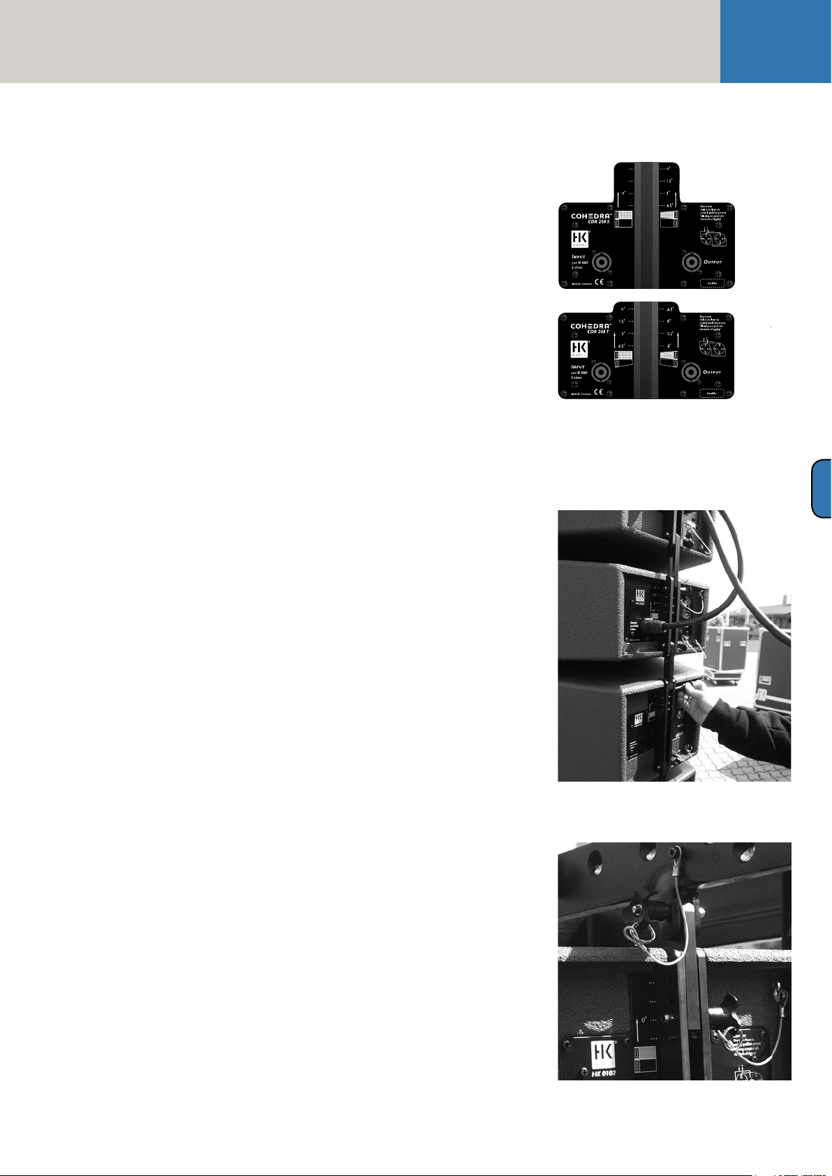
Rigging and Curving COHEDRA® System
5 Determining the
Curving Angle between
Two COHEDRA® Mid/
High Enclosures
The curving angle between two enclosures is set
by simply adjusting one pin. One person can easily
carry out the entire process of curving cabinets.
The maximum adjustable angle depends on how
the mid/high range enclosures are configured in a
flown stacked array. Two different housing designs
are available for optimizing the gap between two
mid/high range enclosures, the straight variant
CDR 208 S (S stands for straight) and the slanted
variant CDR 208 T ( T is short for trapezoidal).
Both COHEDRA® mid/high enclosures (the
CDR 208 T and the CDR 208 S) are labeled uniformly to provide information on the adjustable angle:
The left side of the connector panel designates the
angle if the top enclosure is a CDR 208 S. On the
right is designated the angle if the top enclosure is
a CDR 208 T (see Figure 8 a, b).
If two CDR 208 S enclosures are configured in a
flown stacked array, your only option is 0°.
If one CDR 208 S and one CDR 208 T enclosure
each are configured in a flown stacked array, you
can opt for 0 °, 1.5°, 3 °, or 4.5 °.
If two CDR 208 T enclosures are configured in a
flown stacked array, you can opt for 4.5°, 6°, 7.5°
or 9 °. This variant is an excellent choice when you
want to configure sharply curving down-fills.
The rigging equipment is designed so that the curving angle can still be adjusted when COHEDRA®
mid/high arrays are flown (see Fig. 9).
Do not use powerful chain hoists with low gear
ratios (that is, a powerful force action and a long
lashing strap)! A chain hoist that exerts too much
force relieves the load on the rigging system’s rear
pick-point, which means the pick-point’s force action is distributed unfavorably across the full length
of the rigging frame. This can permanently warp the
rigging frame, thereby voiding the operating permit
Never place or use motors between the rigging
frames for this purpose! This will overload the top
flight frame and impair operating safety!
Important note: If you first mount a CDR 208 S
enclosure to the top rigging frame - that is, configure two CDR 208 S mid/high enclosures in a flown
stacked array - you must insert the back pin into
both the eyelet labeled 0° and through the connector component's slot (see Fig. 10)! Otherwise, the
angle will be set incorrectly and you will not be able
to curve the array as desired!
For every other configuration, do not insert the pin
into the slot!
6 Preparations
The following section describes how to set up a basic
mid/high array. Use the COHEDRA® CAPS software to select on the top rigging frame pick points
for determining the angles between the mid/high
enclosures.
Move the open case with the four mid/high
enclosures in position.
27
Figure 8: The curvature between two COHEDRA®
mid/high enclosures
D
How is this done?
The pin that determines the curving angle (the top
pin on the mid/high unit) is merely a predefined
stop for the flexible connector component when
the entire COHEDRA® mid/high array is pulled
together accordion-style and thereby adjusted using
a lashing strap, chain hoist or motor attached at
the back. If no force is exerted, the entire mid/high
array is suspended at a 0° angle, meaning that the
pin is easily repositioned!
Important notes on safety when curving the array
with lashing straps and chain hoists: When tightening the lashing strap or using a chain hoist, ensure
that just enough force is exerted to curve the array
to the desired extent along the rear of the housings.
Use a chain hoist with a maximum load of 250 kg
(8 m in length). This also suffices for configurations
with up to 24 Mid / High units. If possible, choose
a pick-point for the chain hoist shackle near the top
rigging frame’s rear connector.
Figure 9: Setting the curving angle on a flown array
Figure 10: Connector component attached o the top
rigging frame for a 0 ° curving angle
Page 28
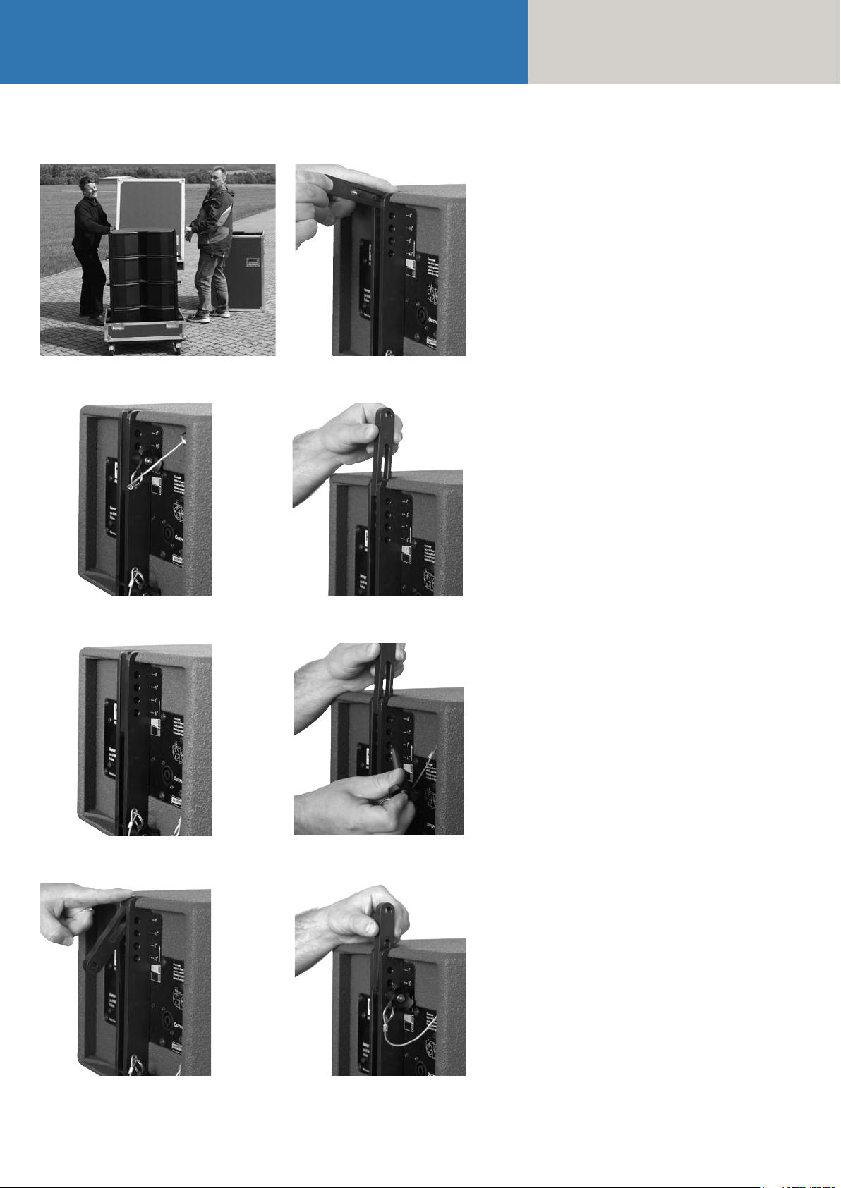
Manual
COHEDRA® & COHEDRA® Compact
Figure 11: Open case with four mid/high range enclosures
Figure 12 d
7 Mounting the
Top Rigging Frame
The tasks described below require two people.
Remove all three quick-release pins from their receptacles on the top rigging frame and the top pin
on the back of the top mid/high range enclosure
(preferably CDR 208 S). Set the top rigging frame
on the topmost enclosure. First attach the two front
connectors. Turn the connector component so that
the rounded side of the component faces forward
(see Fig. 12 a – g). Insert the pin of the top mid/
high enclosure through the slot on the connector
component and into the eyelet labeled 0°.
Figure 12 a
Figure 12 b
Figure 12 e
Figure 12 f
Figure 12 c Figure 12 g
Page 29
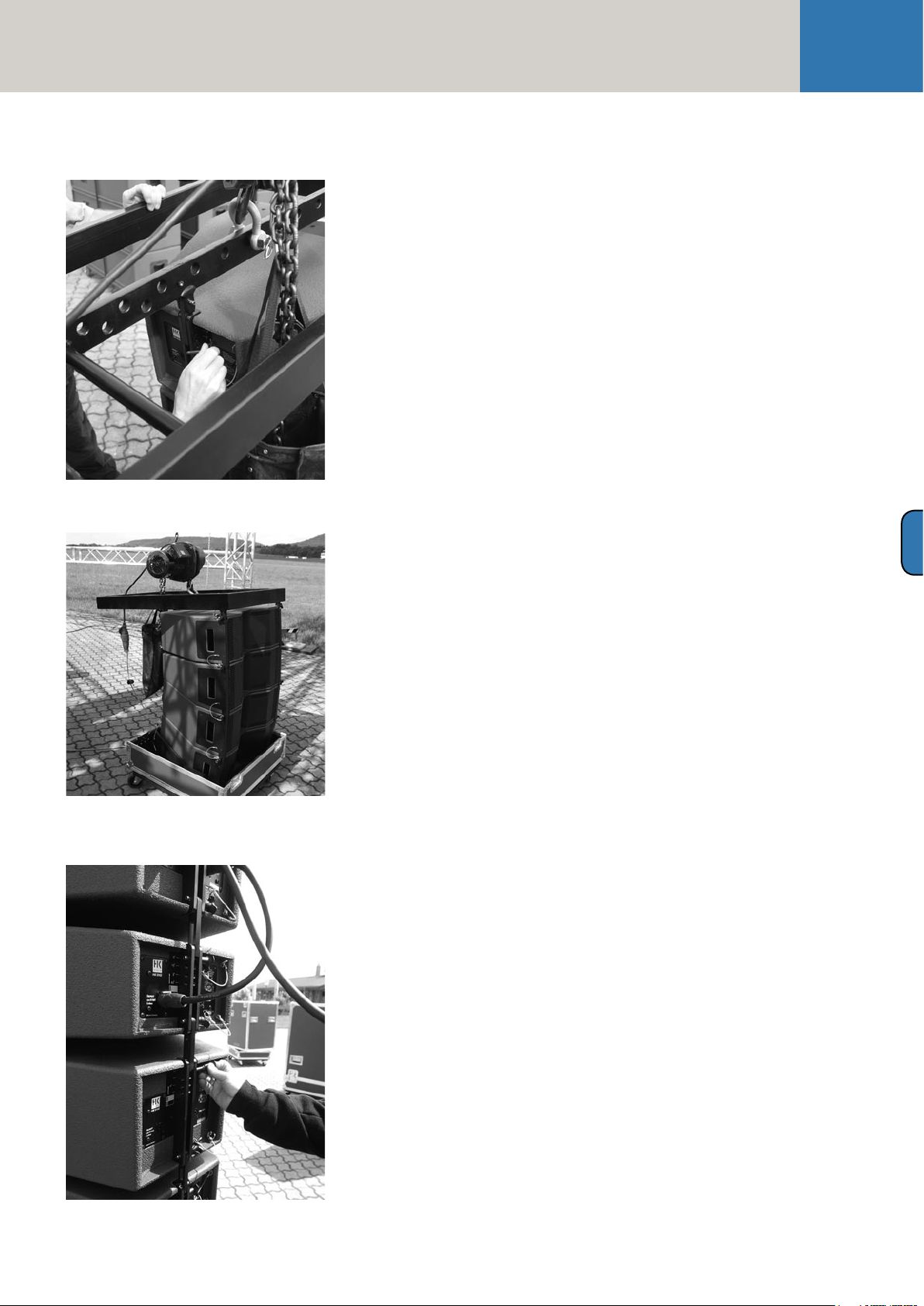
Rigging and Curving COHEDRA® System
Now connect the back of the top rigging frame to
the enclosure (see Fig. 13).
Important note: For this purpose, the pin must be
inserted through the slot and into the 0 °s position!
Always on the CDR 208 S. See Figure 10.
Attach to the top rigging frame the shackle destined
to accept the motor hook (see Fig. 14).
Your choice of pick point depends on how sharply
you aim to curve the COHEDRA® mid/high array.
Note: Use the third eyelet (from the front) to set the
array to a curving angle of about 0°.
Check all pins on the top rigging frame to ensure
they are firmly seated and attach the motor to the
shackle.
Figure 13: Mounting the top rigging frame
Hoist the enclosures from the case using the motor
and roll the case off to the side.
Set the pins on the back of the top four mid/high
enclosures in accordance with the desired application and curving angle.
29
D
Figure 14: Mounting the main motor to the
top rigging frame
This is also a good time to connect the speaker
cables to the four mid/high range enclosures, which
will later be the top cabinets in your array. You can
use the round pole on the top rigging frame to
secure the cables.
Bear in mind that you must attach one of the shackles on the top rigging frame to the lashing strap,
chain hoist or motor that will later pull in the back
of the array to curve out its front face. Do this now.
Tip: If you intend to mount additional mid/high
enclosures, it is recommended that you attach all
the required speaker cables to the top rigging frame
now because this task is made more difficult as the
height of the array increases. Be sure to use cables
of sufficient length!
Figure 15: Setting the curving angle between
COHEDRA® mid/high enclosures
Page 30
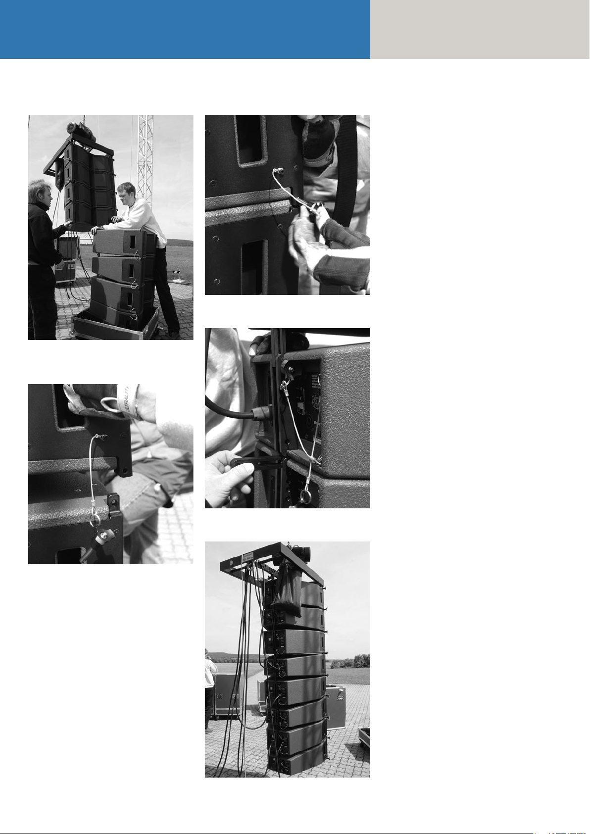
Manual
COHEDRA® & COHEDRA® Compact
Figure 17 b
Figure 16: Hoisting the top four COHEDRA® mid/high
enclosures
8 Mounting Additional
COHEDRA® Mid/High
Enclosures
Hoist the cabinets to a height that allows you to roll
a second case with four mid/high range enclosures
under the array. Remove both front pins from the
lowest flown enclosure and the bottom pin on the
back (see Fig. 16).
Tip: Insert the front pins into the carrying handles
on the sides of the mid/high range enclosure.
This ensures that they are out of the way when the
bottom enclosures are placed in position.
Move the second case with four additional mid/high
enclosures into position. Slowly hoist the top four
cabinets until the two front connectors engage (see
Fig. 17 a). Insert both front pins first, ensuring that
they engage fully and securely. You may have to
shift the two enclosures slightly to ease the pins
into position (see Fig. 17 b). In order to attach the
rear connector component, you must swivel it out
of the rail so that the round end faces up and the
slot faces down (see Fig. 12 a – g for details and
Fig. 17 c)
Figure 17 a: Mounting additional mid/high enclosures
Figure 17 c
Tip: Use the motor to slowly hoist the array, creating
a gap of about 60 to 80 mm at the back between
the two enclosures. This makes it easier to insert
the pin into the top enclosure.
Hoist the COHEDRA® mid/high array with the eight
enclosures just enough to remove it from
the case.
Configure the pins on the back of the bottom four
enclosures to achieve the desired curving angle.
Connect the remaining speaker cables.
Repeat the above procedure to configure even more
mid/high enclosures in a flown stacked array.
Figure 17 d
Page 31

Rigging and Curving COHEDRA® System
31
9 Attaching the Bottom
Rigging Frame and Raising
the Mid/high Array
Once all COHEDRA® mid/high enclosures have
been assembled in the desired array, you must
attach the bottom rigging frame to the lowest enclosure. To do this, remove all three pins from the
lowest enclosure. First attach the front of the bottom
rigging frame and secure it using the pins, and then
insert the rear pin.
Now the enclosures are mounted, speaker cables
are all connected, and the pins are inserted in the
required configuration.
If you want to use the lashing strap to curve the
COHEDRA® mid/high array, connect its hooks to
the bottom rigging frame and, using a shackle, to
the top rigging frame (see Figure 20). Tighten the
strap until it exerts enough force to curve the array
as desired.
The pin that determines the curving angle (the top
pin on the mid/high unit) is merely a predefined
stop for the flexible connector component when
the entire COHEDRA® mid/high array is pulled
together accordion-style and thereby adjusted using
a lashing strap, chain hoist or motor attached at
the back. If no force is exerted, the entire mid/high
array is suspended at a 0° angle, meaning that the
pin is easily repositioned!
Do not use powerful chain hoists with low gear
ratios (that is, a powerful force action and a long
lashing strap)! A chain hoist that exerts too much
force relieves the load on the rigging system’s
rear pick-point, which means the pick-point’s
force action is distributed unfavorably across the
full length of the rigging frame. This can permanently warp the rigging frame, thereby voiding the
operating permit.
Important notes on safety when curving the array
with lashing straps and chain hoists: When tightening the lashing strap or using a chain hoist,
ensure that just enough force is exerted to curve
the array to the desired extent along the rear of
the housings. Use a chain hoist with a maximum
load of 250 kg (8 m in length). This also suffices
for configurations with up to 24 Mid / High
units. If possible, choose a pick-point for the
chain hoist shackle near the top rigging frame’s
rear connector.
Never place or use motors between the rigging
frames for this purpose! This will overload the top
flight frame and impair operating safety!
Figure 18: Mounting the bottom rigging frame
D
Figure 19: Attaching the lashing strap between the top
and bottom rigging frames
Figure 20: Hoisting the fully assembled COHEDRA®
mid/high array
Page 32

Manual
COHEDRA® & COHEDRA® Compact
Figure 21: Groundstack with CDR 210 F Sub
and CDR 208 S/T enclosures
10 Ground Stacking
10.1 Ground Stacking with
the Stack Frame
The stack frame was developed especially for
ground-stacking CDR 208 S/T and CDR 210 F Sub
enclosures. If you are unable to fly the top units or
bass bins, the stack frame provides the underpinning
for setting up stacked mid/high arrays or a fullrange
stacks comprised of CDR 210 F subwoofers and
CDR 210 S/T mid/high units.
The stack frame is equipped with four extendible,
height-adjustable feet. This lets you adjust the
stack to suit the underlying surface. In addition,
the feet are infinitely variable, allowing you tilt the
entire stack forward or back to align the system to
the audience. The stack frame is readily set up and
stowed away in a case. Its removable feet facilitate
handling and transport.
Technical data (preliminary):
Weight: approx. 30 kg / 66 lbs
Base dimensions (with feet fully extended):
approx. 200 cm x 160 cm
Dimensions (dismantled):
approx. 80 cm x 80 cm x 40 cm
Material: Steel w. black enamel coating
10.2 Ground Stacking with
the Rigging Frame
This option is recommended for smaller (four mid/
high units) configurations in venues that do not
allow enclosures to be flown, or when you want to
cover galleries, terraces or balconies.
Place the top rigging frame on the ground or stage
without shackles so that the connector components
for the mid/high enclosures face up. If necessary,
place wooden wedges under the rigging frame to
ensure a stable, secure and level position.
Remove all three pins from the rigging frame and
mount the mid/high enclosures one after another.
The procedure is the same as for a flown system,
apart from the fact that enclosures are stacked upside
down and, due to the weight of the enclosures, a
lashing strap is not required for curving purposes.
Caution: Always secure ground stacks with a
suitable lashing strap to prevent slippage!
11 Setting up Subwoofers
11.1 Sub Array
Figure 22: CDR 210 sub array
In a sub array, individual subwoofers are arranged
side by side. This configuration creates a horizontal
cylindrical wave that makes use of the floor contact.
Space two CDR 210 Sub bins about 0.60 m apart.
Spacing them at distances greater than 0.60 m, lowers the sub array's upper frequency limit. This can
be advantageous when you are consciously aiming
to thin out the 100-to-150 Hz frequency range.
Advantages:
A cylindrical wave loses just 3 dB over twice a given
distance, while a spherical wave loses 6 dB, suffering
twice the loss of effective sound pressure.
A cylindrical wave yields the most uniform low frequency diffusion (comb filtering is not a problem).
Disadvantages:
The bass floor array's vertical angle of projection
is 0° in its near field. In practice, this means you
must ensure that the signal is also projected to the
targeted area on the horizontal plane (that is, to the
right and left). To do this, you may have to add bass
bins to the right and left of the array.
Alternatively, you can spread the cylindrical wave
somewhat by delaying the outside subwoofers (for
example, by using a DFC Sub only rack).
Figure 23: CDR 210 sub cluster
Page 33

Rigging and Curving COHEDRA® System
11.2 Bass Cluster/ Stacking
In the classic right/left stacked configuration, one
half of the bass bins is arrayed to the right of the
stage, the other to the left.
Advantages:
The stacked bass bin configuration depicted above
is a conventional and widely accepted option.
It is very easy to deal with (short cables and
walking distances).
Disadvantages:
Massive comb filtering effects sweep from right
to left, creating peaks and valleys in frequency
amplitude and typical low end drop-outs.
11.3 Bass Clusters in Blocks
33
If you want to deploy many bass bins, arraying them
in blocks is a good option. Note that it is important
to maintain varying distances between individual
blocks.
Advantages:
Different frequencies are cancelled or boosted. The
sum of the comb filters creates a relatively uniform
soundscape. This setup's horizontal directivity is
quite wide, as is typical for bass signals.
Disadvantages:
Though slight, comb filtering effects remain a
problem. Cables and walking distances are longer
than for right/left stacked configurations.
D
Figure 24: CDR 210 sub cluster in blocks
Page 34

Manual
COHEDRA® & COHEDRA® Compact
Figure 25: Flown CDR 210 F bass array next to a
mid/high array
Figure 26: The CDR 210 F Sub’s curving angle
Figure 27: Pin assignment of channels 1-4
12. Flying CDR 210 F Subs
12.1 As an Independent
Bass Array Using A Second
Rigging Frame
Up to 20 CDR 210 F enclosures may be flown in a
stacked array using the standard rigging frame.
Please also read and heed the safety rules discussed
in chapter D of the manual.
The procedure for setting up and mounting subwoofer
arrays is the same as the procedure for CDR 208 T
and CDR 208 S mid/high cabinets described in
the chapter on rigging and curving COHEDRA®
systems. Your choices of curving angles (or splay)
between two flown CDR 210 F Sub cabinets are 0°,
1.5°, 3° and 4.5°.
The array's overall curving will be oriented on the
mid/high array's curving. However, the bass array
may not project beyond the front edge of the mid/
high array to ensure the former does not negatively
influence the latter's response.
Important note:
If you first mount a CDR 210 F Sub enclosure to the
top rigging frame, you must insert the back pin into
both the eyelet labeled 0° and through the connector
component's slot (see Figure 26)! Otherwise, the
angle will be set incorrectly and you will not be able
to curve the array as desired! If you are configuring
two CDR 210 F Sub enclosures in a stacked array
and want the angle to be 0°, do not insert the
connector component through the eyelet (see
figure 26)!
12.2 In Combination with a
Mid/High Array on One
Rigging Frame
Flying the subwoofers and mid/high units together
on one rigging frame can be a workable option,
depending on the application. In these cases,
the subwoofers should be mounted on top.
Mind the rigging frame's maximum permissible
load. Be sure to check the system's overall weight;
you'll find weights listed in the tables 1 and 2 in
chapter D on rigging and curving the system.
The first cabinet to be mounted under the
CDR 210 F Sub should be a CDR 208 S. Use the 0°
option for this cabinet.
13. The SL 218 as a
Bass Supplement
The SL 218 is well-suited for enhancing sub bass
response of both flown and stacked subwoofers.
It is arrayed in a center block or in line between
CDR 210 blocks, depending on the given requirements
and application scenario.
14. Operating the System
We recommend the following procedure to help
prevent errors and troubleshoot problems quickly.
The adverse affect of a mid/high cabinet dropping
out or an incorrect connection can seriously degrade
a line array's performance!
14.1 Connecting Speaker Cords
or Multi-core Cables
Always ensure cables are laid clearly and orderly!
You should be able to attribute enclosures to their
connected power amp channel and/or amp rack at
any time. This ensures flaws such as defective cords
can be pinpointed and repaired swiftly.
Also ensure LSM multi core speaker cables (mid/
high and sub adapters) are labeled appropriately,
that is, from channel 1 to 4 (see the chapter on the
PB 5 in the manual and figure 27).
For example, channel 1 drives the array's two top
mid/high units, channel 2 the two units below to
top pair, and so forth. An LSM mid/high adapter
can serve to drive a total of eight mid/high units.
If more than 8 cabinets are connected, they are
addressed by an additional PB 5, and the channel
1-to-4 numbering system is repeated. See the chapter
on the PB 5 in the manual to learn more about how
to assign power amp channels to the PB 5's channels 1 to 4.
Follow the same systematic approach when
connecting CDR 210 (F) Sub enclosures.
14.2 Activating the PR 8 and
PR 16 Amp Racks
Ensure the VX 2400s' power switches are off and
the gain knobs are turned all the way down. Check
the PB 5's phase switches. They must all be set to
+2 (or +3)! Once you have done this, switch on the
PS 32's circuit breakers on the back of the amp racks.
The DFCs and the PB 5 patch bays are now supplied
with power. First select the appropriate filter for
your set-up on all DFCs (making sure you select
the same set on each!). If you are unsure of how
the amp rack or DFC was used in the previous application (delays, EQ, etc.), as a precaution execute a
hot reset on all DFCs and then select the filter set
on the DFCs! Read the chapter on the DFC in the
Page 35

Rigging and Curving COHEDRA® System
35
manual to learn more about how to do this.
Before you can procedure further, you must first
connect to the amp racks the DFCs' remote line
and all of the system's audio cords.
14.3 Checking Individual Mid/
High Cabinets
The best method of checking cabinets is to play
a familiar song on a CD, routing the signal into
the mixer and out via the master channel. Set the
master level to a low-to-medium setting.
• Turn up the channel's gain knob. You will
hear the signal rendered by the array's two
top mid/high cabinets. The display of the DFC
assigned to this pair should indicate an incoming
signal level.
Important:
If you are located outside the high frequency signal's
directivity radius, you will not be able to hear this
signal! Your best bet is to perform this system check
with a helper position a suitable distance from the
array.
Note: If you can see the bottom of the mid/high
unit as a plane surface, you are outside
its directivity radius!
• Turn the channel 1 gain knob back down after
hearing the signal!
• Follow the same procedure for all other power
amp channels that you want to use.
Be sure to turn the gain knob down after each
successful test!
Note:
With this procedure, you are checking mid/high
cabinets in descending order; that is, from the
top to the bottom. A cabinet's height affects its
directivity, so the lower the cabinets, the closer
the listener should move in towards the array.
• Follow the same procedure for the subwoofers.
• Once you have checked all cabinets successfully,
turn up all gain knobs, one after the other.
• Start with the channel 1 gain knob for the two top
mid/high units, and then turn up the channel 2
gain knob, and so forth. With every additional
channel that you activate, you should hear a boost
in low midrange response. If not, this may be due
to a phase inversion in the NF (or in extreme cases,
in the speaker cords)! Also check the PB 5's phase
switch again.
• Proceed in the same manner for the subwoofer
channels.
14.4 Configuring the Controller Network with the Audio
Controller Software
Once you have performed these tests, you can
configure the controller network. The type and size
of the configuration of course depends on the given
sound reinforcement task (PA left/right, center,
outfills, etc.)
Read the chapter G about the DFC software in the
manual to learn more about networking controllers,
creating groups and setting delays and levels.
15. Disassembling and
Removing the System
As the saying goes: To disassemble the system,
proceed in the reverse order of assembly.
These ten tips should make the job of dismantling
the mid/high array easier:
1. Lower the array until the caster-equipped bottom
of the mid/high case fits under it.
2. Engage the motor or chain hoist to relax the ten-
sion on the strap that is curving the array.
Caution: The array may belly out towards the
front!
3. Disconnect the four lower cabinets' cords.
4. Set these cabinets' curving pins to the maximum
angle! This ensures that the array will not buckle
quite as drastically when lowering and setting
it on the bottom of the case. This also makes it
easier to dismantle the four-cabinet block.
5. Remove the lower rigging frame.
6. Always insert the front pins into the rigging
connector receptacles to ensure that they are not
damaged or torn off when the array is lowered
onto the case!
7. Adjust the angle of the mid/high case's bottom.
Set it to 0° if the lower cabinet of the four-cabinet
block is a CDR 208 S, and to 4.5º if it is a
CDR 208 T.
8. Carefully lower the array into the case. First re-
move the rear pin connecting the two mid/high
units. Then remove both front pins and place
them in the recessed grips so they're out of your
way and out of harm's way.
9. Raise the array slightly so that the lower four-bin
block can be rolled away.
10. Do not leave the connector component of the
rear rigging rail (which is now on the top cabinet of the four-bin block in the case) extended!
Remove the pin that sets the curving angle,
fold down the connector component, and insert
the pin through the connector component and
eyelet.
D
Page 36

Manual
COHEDRA® & COHEDRA® Compact
Chapter D 1
Rigging & Curving the COHEDRA® Compact System
1 Use
1.1 Intended Use .................................................. 37
1.2 Unintended Use ............................................. 37
2 Warranty and Liability .................................... 37
Important Notes on Safety ............................. 37
2.1 Responsibilities of the Operator .................... 38
2.2 Storage, Maintenance, Inspection and Repair
of COHEDRA® Compact Rigging Hardware ... 38
2.3 Technical Specifications of
COHEDRA® Compact Rigging Hardware ....... 38
2.4 Maximum Permissible Number of flown
COHEDRA® Compact Mid/High Units .......... 38
2.5 Maximum Permissible Number of flown
COHEDRA® Compact CDR 210 C Subwoofers ..39
2.6 Pick Points for Flying COHEDRA®
Compact Enclosures ....................................... 39
2.7 Structural Modifications of
COHEDRA® Compact Rigging Hardware ....... 39
2.8 Original HK Audio® Accessories: ................... 39
2.9 Initiation and Operation ................................ 39
3 Components and Applications of
COHEDRA® Compact Rigging Hardware ..... 40
3.1 Flying Enclosures Using Quick-release Pins ...40
3.2 Flying Arrays with Lightweight Rigging
Frames ........................................................... 41
4 Determining the Splay Between
Two CDR 108 C Enclosures ........................... 41
4.1 Compression Mode ........................................ 41
4.2 Fixed Mode .................................................... 43
5 Flying CDR 210 C Subwoofers ...................... 44
5.1 Components ...................................................44
5.2 As an Independent Bass Array on
a Second Rigging Frame .................................44
5.3 In Combination with CDR 108 C Mid/ High ...44
6 Setup CDR 210 C Subwoofer ....................... 44
7 Ground-stacking ........................................... 45
7.1 Without Subwoofer ........................................ 45
7.2 With CDR 210 C Subwoofers .......................... 45
8 Operating the System ................................... 46
8.1 Connecting Speaker Cords .............................46
8.2 Activating PR 8 and PR 16 Amp Racks ............46
8.3 Checking Individual Mid/High Enclosures .....46
8.4 Configuring the Controller Network
Using Audio Controller Software ....................46
Index of Figures:
Fig. 1: COHEDRA® Compact Mid/High case .... 37
Fig. 2: 16 COHEDRA® – CDR 108 C .................40
Fig. 3: CDR 108 C with integrated
rigging attachments ...............................40
Fig. 4: COHEDRA® Compact
standard rigging frame ..........................40
Fig. 5: COHEDRA® Compact
lightweight rigging frame .......................40
Fig. 6: Optional quick-release pins for
flying up to six CDR 108 C enclosures ....40
Fig. 7: Shackles for attaching motors, straps ....40
Fig. 8: Lashing strap for curving the array
in compression mode ............................40
Fig. 9: Quick-release pin ...................................40
Fig. 10: Horizontal array comprising three
CDR 108 Cs ............................................ 41
Fig. 11: CDR 108 C set angle in compression
mode: 4.5° .............................................. 41
Fig. 12: Open case with four
CDR 108 C enclosures ............................ 41
Fig. 13: Rigging frame set to 0° .......................... 41
Fig. 14: Setting an interim angle ........................ 42
Fig. 15: Mounting the standard
rigging frame ......................................... 42
Fig. 16: Setting the splay to curve
a CDR 108 C array ..................................42
Fig. 17: Hoisting the top four
COHEDRA® Compact Enclosures ..........42
Fig. 18
a, b, c: Rigging additional
CDR 108 C enclosures ............................42
Fig. 19: Attaching the lashing strap .................... 43
Fig. 20: Example fixed mode application
with 4.5° angle ....................................... 43
Fig. 21: CDR 210 C Rigging Set ...........................44
Fig. 22: CDR 210 C Subwoofer Cluster ................44
Fig. 23: Ground stack with the
standard rigging frame .......................... 45
Fig. 24: Ground stack with
CDR 210 C subwoofers .......................... 45
Index of Tables:
Table 1: Weights of COHEDRA® Compact
mid/high enclosures .............................. 38
Table 2: Weights of COHEDRA® Compact
CDR 210 C subwoofers .......................... 39
Table 3: Angle between the rigging frames
and first mid/high unit .......................... 39
8 Tearing Down and Transporting the System ..... 12
Page 37

Rigging and Curving COHEDRA® Compact System
37
Rigging COHEDRA® Compact Systems
Please read these instructions carefully before you
begin setting up the system!
1 Use
1.1 Intended Use
Specifications for intended use include the following:
• When rigging enclosures, make sure that the load
is centered directly under the suspension point
on the rigging frame.
• The rigging frame may be tilted (not to be confused
with curved!) no more than 10% (6°). Note that
the specifications for intended use require you
to read and heed all of the operating instructions
and comply with inspection and maintenance
requirements.
Any use other than specified is unintended.
The manufacturer shall not be liable for damages
resulting from unintended use.
1.2 Unintended Use
Improper use of rigging frames and incorrect
handling of this load-carrying equipment can pose
a serious danger. Never
• use rigging frames to exert diagonal force or
tension on loads,
• use a crane to dislodge stuck or immovable loads,
• lift people,
• strike, knock or dent rigging frames,
• heat-treat or weld rigging frames,
• exceed the truss’s maximum load-carrying capacity.
Note that in addition to the above specifications,
the operational safety regulations of VBG 9 (accident
prevention regulations of the German employers’
liability insurance association) apply.
2 Warranty and Liability
HK AUDIO® shall not be held responsible for damages due to improper use or non-compliance with
the safety specifications for setup and operation.
All warranty and liability claims for personal injury
and property damages are excluded if attributable
to one or several of the following:
• non-compliance with operating manual instructions,
voiding product liability and warranty claims
• unintended use of rigging frames
• non-compliance with operating manual instructions
regarding transportation, storage, initial setup,
operation, maintenance and repair of rigging frames
• unauthorized structural modifications performed
on rigging frames
• unauthorized modification of the parameters
indicated in the operating manual
• inadequate or improper repairs
Important Notes on Safety
Original COHEDRA® rigging accessories have been
certified as a complete and cohesive system by
the safety standards authority TÜV. The COHEDRA®
rigging system’s provisions for use require that it be
installed in accordance with the following specifications. Before you begin installation, ensure that the
rigging points (for example, a chain hoist) on the
stage roof or
the venue’s ceiling comply with BGV-C1 accident
prevention regulations and that the safety standards
authority TÜV has certified them for the full load
(see table 1). Prior to every installation, inspect all
components to ensure they are in good operating
condition, taking particular care to confirm that all
quick-release pins and hardware connectors are
undamaged.
The principle requirement for safe handling and
trouble-free operation of rigging frames is a thorough
understanding of fundamental operating safety and
safety regulations.
This operating manual contains important instructions on the safe operation of rigging frames.
Figure 1: COHEDRA® Compact Mid/High case
D 1
Page 38

Manual
COHEDRA® & COHEDRA® Compact
2.1 Responsibilities of
the Operator
As the operator, you are obligated to allow only those
persons to work with rigging frames who are
• 16 years of age or older,
• physically and mentally able, familiar with the basic
rules of industrial safety and accident prevention,
and trained in the handling of rigging frames.
Be sure to regularly review and confirm personnel’s
working safety awareness.
In addition, task personnel with specific responsibilities for setting up, putting into service, operating,
maintaining, and repairing equipment.
Ensure that personnel are trained to work with
the rigging frame only under the supervision of a
proficient and experienced technician. Ensure also
that defects, flaws and other damage that could
impede safety are repaired immediately.
2.2 Storage, Maintenance,
Inspection and Repair of
COHEDRA® Compact
Rigging Hardware
Storage and safekeeping when not in use
When not in use store the rigging frame in a safe
place where it cannot be tipped over and is
protected from exposure to the elements.
Inspections
§ 39, VBG 9a of the German employers’ liability
insurance association’s accident prevention
regulations requires that load-carrying equipment
be inspected by a qualified expert and possible
defects be eliminated prior to initial commissioning
by the recipient.
§ 40, VBG 9a requires that load-carrying equipment
be inspected at least annually for cracks.
When used in dynamic applications, equipment
must be inspected for cracks every six months.
Maintenance
You are authorized to replace easily serviceable
wearing or standard parts in accordance with the
manufacturer’s instructions. Use original parts
for this purpose.
Tighten screws and bolted connections whenever
necessary.
Repair
In the event that parts of the load-carrying equipment have been deformed, it is up to the manufacturer to determine if they are repairable.
Solely the manufacturer is authorized to perform
welding and repair jobs on load-carrying equipment.
2.3 Technical Specifications
of COHEDRA® Compact
Rigging Hardware
Load-carrying capacity of the rigging frame: 350 kg
Test load: 2,100 kg
Ambient temperature when in operation: min. –10° C,
max. + 60° C
2.4 Maximum Permissible
Number of Flown COHEDRA®
Compact Mid/High Units
No more than 16 mid/high range enclosures may
be flown in a stacked array.
• Up to 16 mid/high range enclosures may be flown
in a stacked array with the standard rigging frame.
• No more than 6 mid/high range enclosures may
be flown in a stacked array when using the lightweight rigging frame.
• No more than 6 mid/high range enclosures may
be flown in a stacked array when using quick-release pins. In addition, be sure to mind the quickrelease pins’ maximum permissible load!
Warning:
Flying more than 16 enclosures in a stacked array
voids the safety standards authority TÜV’s certification!
Refer to table 1 to determine flown loads. The sum
of the weights of COHEDRA® Compact mid/high
enclosures plus the weight of the rigging frames
equals the total load.
Note: Ensure that you add the weights of chain
hoists, motors, cables and further stops to determine total weight!
Quantity Weight [kg] [lbs.]
1 18 40
2 36 79
3 54 119
4 72 158
5 90 198
6 108 238
7 126 277
8 144 317
9 162 356
10 180 396
11 198 436
12 216 475
13 234 515
14 252 554
15 270 594
16 288 634
Weight of the standard rigging frame with shackles:
10.5 kg/ 23.10 lbs.
Table 1: Weights of COHEDRA® Compact mid/high enclosures
Page 39

Rigging and Curving COHEDRA® Compact System
39
2.5 Maximum Permissible
Number of Flown COHEDRA®
Compact CDR 210 C Subwoofers
• No more than six CDR 210 C subwoofers may be
flown in stacked array with the standard rigging
frame.
Warning: Flying more than six subwoofers in stacked
array voids the safety standards authority TÜV’s
certification!
CDR 210 C subwoofers and CDR 108 C mid/high
units may also be flown together on one rigging frame.
Refer to table 2 to determine flown loads. The sum
of the weights of CDR 210 C subwoofers and
COHEDRA® Compact mid/high enclosures plus the
weight of the rigging frames equals the total load.
Note: Ensure that you add the weights of chain
hoists, motors, cables and further stops to determine
total weight!
Quantity Weight [kg] [lbs.]
1 48 105.6
2 96 211.2
3 144 316.8
4 192 422.4
5 240 528
6 288 633.6
Weight of the standard rigging frame with shackles:
10.5 kg/ 23.10 lbs.
Accessories
Use original HK AUDIO® parts only (see chapter 3)!
The safety standards authority TÜV has not certified
any other parts for use! Always install parts in
accordance with these installation instructions!
Compile and store all documents pertaining to
the system in a safe place!
2.9 Initiation and Operation
§ 39, VBG 9a of the German employers’ liability
insurance association‘s accident prevention regulations requires that load-carrying equipment be
inspected by a qualified expert and possible defects
be eliminated prior to initial commissioning by
the recipient.
§ 41 VBG 9a requires that load-carrying equipment
be subjected to a non-routine inspection following
damage, repair work and other incidents that can
affect load-carrying capacity.
D 1
Table 2: Weights of COHEDRA® Compact
CDR 210 C subwoofers
2.6 Pick Points for Flying
COHEDRA® Compact Enclosures
Use only the top rigging frame’s shackles to attach
motors, chain hoists and straps. Shackles are inserted
into the elongated holes in the center rail!
Clear the area below arrays immediately of people
before raising or lowering loads.
Lift and lower flown mid/high enclosures smoothly,
avoiding abrupt stops or jerky motions.
Secure the flown array with straps to prevent it from
moving, for example, in the event of wind.
2.7 Structural Modifications
of COHEDRA® Compact
Rigging Hardware
No structural modifications may be made without
the manufacturer’s consent. This also applies to
welding work performed on supporting parts. Structural alterations require the manufacturer’s written
approval. Use original replacement and wearing
parts only.
2.8 Original HK Audio®
Page 40

Manual
COHEDRA® & COHEDRA® Compact
Figure 5: COHEDRA® Compact lightweight rigging
frame
Figure 6: Optional quick-release pins for flying up to
six CDR 108 C enclosures
3 Components and
Applications of
COHEDRA® Compact
Rigging Hardware
COHEDRA® Compact rigging hardware consists of
the following parts:
• a standard rigging frame with two shackles for
attaching motors, lashing straps or chain hoists.
The rigging frame also serves as the base for
ground stacks if the array is not stacked on
CDR 210 C subwoofers.
• an optional lightweight rigging frame for flying
up to eight CDR 108 C enclosures.
• side-mounted, recessed rigging points designed
to accept optionally available quick-release pins
for up to six CDR 108 C enclosures.
• an optional two-part lashing strap for curving the
array in compression mode.
• integrated rigging points on the side and back
for flying COHEDRA® Compact enclosures
• four quick-release pins per CDR 108 C for
connecting the enclosure to rigging frames.
Figure 2: 16 COHEDRA® – CDR 108 C
Figure 3: CDR 108 C with integrated rigging attachments
Figure 7: Shackles for attaching motors, straps
Figure 8: Lashing strap for curving the array in
compression mode
Important note on pins: Quick-release pins serve to
connect rigging hardware and speaker enclosures,
and their proper function must be tested and verified.
The pins must always engage fully in the (fitted)
hole. Under no circumstances may these pins
release on their own when subjected to tractional
forces. The nib in the center of the pinhead must
always be depressed to insert pins; it releases the
ball detents in front. Once the pin engages in the
hole, the nib must glide back to its initial position.
3.1 Flying Enclosures Using
Quick-release Pins
Small Applications
For small applications (up to six CDR 108 C), you
may use two quick-release pins instead of a rigging
frame. These are inserted into the top enclosure’s
designated side holes. The holes accept 10-mm
pins (see Fig. 6. Be sure to mind the quick-release
pins’ permissible load as well as the manufacturer’s
safety guidelines!
Figure 4: COHEDRA® Compact standard rigging frame Figure 9: Quick-release pin
Page 41

Rigging and Curving COHEDRA® Compact System
41
Setting Up a Horizontal Array
You can configure up to three CDR 108 C enclosures
in a horizontal array using quick-release pins. Connect
three CDR 108 C enclosures and set the splay between
the enclosures for fixed mode and in accordance with
the given requirements. To learn more about this,
read the chapter Determining the Splay Between Two
CDR 108 C Enclosures. To do this, you will need two
quick-release pins with 10-mm uptake and adequate
load-carrying capacity. Mount these to the outermost
enclosures, where they will serve as fixing points for
flying the rig (see Fig. 10).
3.2 Flying Arrays with Lightweight Rigging Frames
As an alternative to the standard rigging frame that
flies up to sixteen CDR 108 C enclosures, you can
opt to use the lightweight rigging frame designed
to accommodate up to six CDR 108 Cs. The rigging
procedure is the same as for the standard rigging
frame. However, the lightweight rigging frame may
be adjusted to the 0° position only on the rear rigging
connector!
4 Determining the Splay
Between Two CDR 108 C
Enclosures
You have two options for setting the splay between
CDR 108 C enclosures - compression mode and fixed
mode. In compression mode, the angle is easily
adjusted after the array has been flown. This requires
a lashing-strap or chain hoist. In fixed mode, the angle
is determined during setup and the flown array cannot
be adjusted later. This option does not require a
lashing-strap or chain hoist. Compression mode
is recommended for setups comprising 12 to 16 mid/high enclosures; fixed mode for smaller configurations.
4.1 Compression Mode
Determine the splay between two enclosures by
adjusting a single pin (Set Angle). One person can
easily perform the entire process of curving arrays.
The following angles may be adjusted between two
CDR 108 C enclosures: 0°, 1.5°, 3°, 4.5°, 6°, 7.5° and 9°.
array is compressed accordion-style at the back and
thereby adjusted using a lashing strap or chain hoist.
When no force is exerted, the entire mid/high array
is suspended at 0°, meaning that the pin (Set Angle)
is easily repositioned (see Fig. 11)!
Important note: The pin labeled Link connects
individual CDR 108 C cabinets. Ensure this pin
is inserted, otherwise the enclosures will not be
connected to each other and may swing forward!
Preparations
The following section describes how to set up an
array in compression mode. Use COHEDRA® CAPS
to select rigging frame pick points for determining
the angles between CDR 108 C enclosures.
Move the open case with the CDR 108 C enclosures
in position. Remove the top cover.
Mounting the Rigging Frame
The tasks described below require two people.
Remove the quick-release pins from the rigging frame
and the two pins on the back of the top CDR 108 C
enclosure. Set the rigging frame on the enclosure.
First attach the two front connectors. Turn the rigging
frame’s connector component down and slide it
into the rear rigging connector.
Important:
The standard rigging frame’s connector component
is longer than that of mid/high cabinets. This means
that you can also set ascending angles, for example,
for covering balconies, terraces, etc. Bear in mind
that a 0° angle between rigging frames and the first
1 CDR 08 C enclosure is set using the hole labeled
9° on the mid/high unit (see Table 3)! To mount the
rigging frame, always employ the fixed mode option
as follows:
Insert the first pin through the hole labeled 9° on
the enclosure and attach the connector component
by inserting the second pin through the slot into the
hole labeled 6° (see Fig. 13).
Attach to the top rigging frame the shackle destined
to accept the motor hook (see Fig. 14). Your choice of
pick point depends on how sharply you aim to curve
the array later.
Figure 10: Horizontal array comprising three CDR 108 Cs
D 1
Figure 11: CDR 108 C set angle in compression mode: 4.5°
Figure 12: Open case with four CDR 108 C enclosures
The rigging equipment is designed so that the splay
can be adjusted when COHEDRA® Compact arrays
have been lifted.
How is this done?
The pin that determines the splay (Set Angle) is
merely a predefined stop for the flexible connector
component when the entire COHEDRA® Compact
Figure 13: Rigging frame set to 0°
Page 42

Manual
COHEDRA® & COHEDRA® Compact
Note: Depending on application, you may not be
able to select a pick point with a shackle. In this
case, use two shackles and a suitable O ring as
shown in Figure 14.
Check all pins on the top rigging frame to ensure
they are firmly seated and attach the motor to the
shackle.
Figure 14: Setting an interim angle
Figure 15: Mounting the standard rigging frame
Figure 18 a: Rigging additional CDR 108 C enclosures
Important: Ensure the motor’s chain bag hangs freely and does not rest on the rigging frame!
Remove the two front pins of the lowest enclosure
and fold down its connector component. Now you
can rig the second two-cabinet block. Curve the
four CDR 108 C enclosures as desired for the given
application by setting the pins on the back accordingly
(see chapter 3.1). Determine the desired angle using
the pin labeled Set Angle.
This is also a good time to connect the speaker
cords to the four enclosures that will later be at the
top of the array. Bear in mind that you must attach
one of the shackles on the rigging frame to the lashing
strap or chain hoist that will later serve to pull back
the ends of the array to curve out its front face.
Do this now.
Tip: If you intend to rig additional CDR 108 C enclosures, it is recommended that you attach all the
required speaker cords to the top rigging frame
now because this task is made more difficult as the
height of the array increases. Be sure to use cords
of sufficient length!
Figure 16: Setting the splay to curve a CDR 108 C array
Figure 17: Hoisting the top four
COHEDRA® Compact Enclosures
Figure 18 b
Figure 18 c
Rigging Additional COHEDRA® Compact Enclosures
Hoist the mid/ high cabinets to a height that allows
you to roll a second case holding four CDR 108 C
enclosures under the array. Remove the two front
pins from the lowest flown enclosure.
Move the second case with four additional CDR 108
C enclosures into position. Slowly lower the top
four cabinets until the two front connectors engage.
Insert the two front pins first, ensuring that they
engage fully and securely (see Fig.e 18 a). You may
have to shift the two enclosures slightly to ease the
pins into position. In order to attach the rear connector component, you must swivel it out of the rail
so that the round end faces up and the slot faces
down (see Fig. 18 b). To connect the two blocks, insert the pin through the connector’s elongated hole
and through the hole labeled Link.
Page 43

Rigging and Curving COHEDRA® Compact System
Hoist the COHEDRA® Compact array with the eight
enclosures just high enough to remove it from
the case.
Insert the pins on the back of the bottom four
enclosures’ Set Angle holes to achieve the desired
curving angle. Connect the remaining speaker cords.
Repeat the above procedure to configure even more
CDR 108 enclosures in a flown stacked array.
Raising the System
The enclosures are rigged, speaker cords are all
connected, and the pins are set in the required
configuration. If you want to use the lashing strap
to curve the COHEDRA® Compact array, connect
one of its hooks to the rigging frame. Using a
shackle (an 8-mm bolt), attach the hook on the
other end to the bottom bin (best to the connector
component).
Tighten the strap until it exerts enough force to
curve the array as desired.
43
Figure 19: Attaching the lashing strap
Once you have hoisted the COHEDRA® Compact
array, secure it against gusts of wind or accidental
twisting using two lashing straps or ropes.
4.2 Fixed Mode
To determine the splay between two enclosures in
fixed mode, you must insert one pin (Set Angle) and
fix the connector component in place with the second
pin. To fix the selected angle, insert the pin into the
neighboring hole labeled Link above the selected
angle (Set Angle). This fixes the connector component
in place so that it is immobile in all directions (See
Fig. 20).
This option gives you the same splay options between
two CDR 108 C enclosures to choose from – that is,
angles of 0°, 1.5°, 3°, 4.5°, 6°, 7.5° and 9°.
To set up the system, follow the same procedure
described for compression mode. Often when arrays
are sharply curved it becomes difficult to rig additional
blocks. In this event, you must mount enclosures
separately from below.
D 1
Figure 19: Example fixed mode application with 4.5° angle
Page 44

Manual
COHEDRA® & COHEDRA® Compact
Figure 21: CDR 210 C Rigging Set
Figure 22: Setting up CDR 210 C subwoofers in a cluster
5 Flying CDR 210 C
Subwoofers
5.1 Components
The following components are required to fly
CDR 210 C subwoofers:
• a standard rigging frame.
• the pick points on the side panels of COHEDRA®
Compact CDR 210 C subwoofers
• the CDR 210 C Rigging Set consisting of four
connector components and eight pins
5.2 As an Independent Bass Array
on a Second Rigging Frame
The standard rigging frame is certified to fly up to
six CDR 210 Cs in stacked array. Read and heed also
the safety regulations in chapter C of the manual.
Rigging
Set the standard rigging frame on the CDR 210 C
subwoofer with the rubber feet facing down. Remove
the four pins on the rigging frame. Attach the four
(optional) connector components between the rigging
frame and the CDR 210 C using the pins. Attach the
shackles for the motor to the rigging frame. Attach
the motor to the shackle and lift the subwoofer.
Now you can rig additional CDR 210 C bins below
this subwoofer. To do this, you need four connector
components and eight pins for each subwoofer.
(=1Set)
6 Configuring CDR 210 C
Subwoofers in Clusters
CDR 210 C enclosures have been optimized for
setting up clusters comprising four subwoofers.
When configuring a cluster, set up the bins so that
the bass reflex apertures point toward each other.
This ensures the various subwoofers’ low-frequency
signals couple for maximum sonic effect. To this end,
set one row of speakers bottom side up (see Fig. 22).
The housings are equipped with feet on the bottom
and top panels. Refer to the labels on the connector
panel for details.
5.3 In Combination with
CDR 108 C Mid/High
Configuring subwoofers and mid/high units together
in a single array can be a viable option, depending
on application. Subwoofers must be rigged on top
of the flown array for this application.
Mind the rigging frame’s maximum permissible load.
Before you begin, add up the individual components’
weights to determine total system weight. Refer to
tables 1 and 2 for weight specifications.
Page 45

Rigging and Curving COHEDRA® Compact System
45
7 Ground-stacking
This option is recommended for smaller venues,
for example, in which enclosures cannot be flown,
or when you want to align the array to cover galleries,
terraces or balconies. You can configure stacks with
or without CDR 210 C subwoofers, as the given
application may require. In both cases, you must
use a standard rigging frame as the base for the
mid/high cabinets.
7.1 Without Subwoofers
Set the standard rigging frame, without shackles
and with the rubber feet facing down, on the
ground, bass bins or stage so that the rigging frame’s
center connector component for the CDR 108 C
enclosures faces up.
Remove the front pins from the rigging frame and
mount the CDR 108 C enclosures upside down.
Proceed as you would to rig a flown system, except
that you do not need a lashing strap to curve the
array. The enclosures’ weight enables the array to be
curved. Maximum stability is achieved in fixed mode.
7.2 With CDR 210 C Subwoofers
Depending on application, use two or three CDR 210 C
subwoofers as the base of the stack. Stack the desired
number of subwoofers and then mount the standard
rigging frame using four connector elements by
following the procedure described in section 7.1
for stacking mid/high cabinets.
Important note:
When configuring ground stacks comprised of three
CDR 210 Cs and four to six CDR 108 Cs, subwoofers
must be linked using connector elements!
Figure 23: Groundstack with flying frame
D 1
Note:
You can shift the mid/high stack’s center of gravity
inwards to make it more stable. Use the two holes
on the sides of the rigging frame to do this. They
are located about 70 mm inwards, measured from
the rear edge (see Fig. 24 a, b).
What’s more, you can adjust the rigging frame’s center
connector component on the lowest CDR 108 C
enclosure to tilt the stack 9° downwards. To do this,
use the set angles in fixed mode! The table below
indicates which angle between the rigging frame
and the first mid/high unit will give you the desired
down-tilt:
Desired down-tilt Label on the CDR 108 C
0° (horizontal) 9°
1.5° 7.5°
3° 6°
4.5° 4.5°
6° 3°
7.5° 1.5°
9° (maximum) 0°
Table 3: Angle between the rigging frame and the first
mid/high unit
Figure 24 a): normal pin position, b): shifted pin position
Caution:
Always secure ground stacks with a suitable lashing
strap to prevent slippage!
Figure 25: Groundstack with CDR 210 C subwoofer
Page 46

Manual
COHEDRA® & COHEDRA® Compact
8 Operating the System
We recommend the following procedure to help
prevent errors and troubleshoot problems quickly.
The adverse effect of a mid/high cabinet dropping
out or an incorrect connection can seriously degrade
a line array’s performance!
8.1 Connecting Speaker Cords
Always ensure cables are laid out clearly and orderly!
You should be able to attribute enclosures to their
connected power amp channel and/or amp rack at
any time. This ensures flaws such as defective cords
can be pinpointed and repaired swiftly.
Example setup using a PB 5:
Channel 1 drives the array’s four (two or three) top
mid/high units, while channel 2 drives the four units
below that, and so forth. Thus, one HK AUDIO®
LS cable can serve to drive a total of four mid/high
units per channel.
If more cabinets are connected, they are addressed
by an additional PB 5, and the channel 1-to-4
numbering system is repeated. See the chapter
on the PB 5 in the manual to learn more about
how to assign power amp channels to the PB 5’s
channels 1 to 4.
Take the same systematic approach when connecting
CDR 210 C subwoofers.
8.2 Activating Amp Racks
PR 8 and PR 16
Ensure the VX 2400s’ power switches are off and
the gain knobs are turned all the way down. Check
the Phase switches on the PB 5s or PB 2s. They
must all be set to +2 (or +3)! Once you have done
this, switch on the PS 32 circuit breakers on the
back of the amp racks. The DFCs and the PB 5 patch
bays are now supplied with power. First select the
appropriate filter for your setup on all DFCs (making
sure you select the same set on each!). If you are
unsure of how the amp rack or DFC was used in the
previous application (delays, EQ, etc. settings), as
a precaution carry out a hot reset on all DFCs and
then select the filter set on the DFCs! Read the
chapter on the DFC in the manual to learn more
about how to do this.
Before you can continue, you must first connect to
the amp racks the DFCs’ remote line and all of the
system’s audio cords.
8.3 Checking Individual Mid/
High Enclosures
The best method of checking cabinets is to play a
familiar song on a CD, routing the signal into the
mixer and out via the master channel. Set the master
level to a low-to-medium setting.
• Turn up channel 1’s gain knob. You will hear the
signal rendered by the array’s four top mid/high
cabinets. The display of the DFC assigned to this
pair should indicate incoming signal levels.
Important note: If you are located outside the high
frequency signal’s directivity radius, you will not
be able to hear this signal! This system check is
best performed with a helper positioned a suitable
distance from the array.
The rule of thumb is, if you can see the bottom
of the mid/high unit as a plane surface, you are
outside its directivity radius!
• Turn the channel 1 gain knob back down after
hearing the signal!
• Follow the same procedure for all other power
amp channels that you want to use. Be sure to
turn the gain knob down after each successful test!
Note: With this procedure, you are checking mid/high
cabinets in descending order; that is, from top to
bottom. A cabinet’s height affects its directivity, so
the lower the cabinets, the closer the listener should
move in towards the array.
• Follow the same procedure for the subwoofers.
• Once you have checked all cabinets successfully,
turn up all gain knobs, one after the other.
• Start with the channel 1 gain knob for the top mid/
high units, and then turn up the channel 2 gain
knob, and so forth. With every additional channel
that you activate, you should hear a boost in low
midrange response. If not, this may be due to a
phase inversion in the NF (or in extreme cases, in
the speaker cords)! Also check the PB 5’s or
PB 2’s Phase switch again.
• Proceed in the same manner for the subwoofer
channels.
8.4 Configuring the
Controller Network Using
Audio Controller Software
Once you have performed these tests, you can
configure the controller network. The type and size
of the configuration of course depends on the given
sound reinforcement task (PA left/right, center,
out-fills, etc.).
Read the chapter on DFC software in the manual to
learn more about networking controllers, creating
groups and setting delays and levels.
Page 47

Rigging and Curving COHEDRA® Compact System
9 Tearing Down and
Transporting the System
As the somewhat clichéd but certainly true adage
goes: To disassemble the system, proceed in the
reverse order of assembly.
These tips should make the task of tearing down the
mid/high array easier:
1 Lower the array until the bottom of the mid/high
case fits under it.
2 Engage the motor or chain hoist to relax the tension
on the strap that is curving the array.
Caution: The array may belly out towards the
front!
3 Disconnect at least the four lower cabinets’ cords.
4 Set the Set Angle pins that are determining the
array’s curving to 0°! This way the array will not
buckle when lowering and setting it on the bottom
of the case. This also makes it easier to dismantle
the four-cabinet block.
5 Always insert the front pins into the holes on the
rigging connector to ensure they are not damaged
or torn off when the array is lowered onto the case!
6 Carefully lower the array into the case. First remove
the rear Link pin connecting the two mid/high
units. Then remove the two front pins. Raise the
array slightly so that the lower four-bin block can
be rolled away.
47
D 1
Page 48

Manual
COHEDRA® & COHEDRA® Compact
Chapter E
Setup with Caps
1 Introduction ....................................................49
1.1 Acoustic Simulation for Line Arrays ............... 49
1.2 Remarks on SPL Calculation in CAPS ...............50
1.3 The Purpose of CAPS ....................................... 51
2 Installing and Launching CAPS ........................51
2.1 System Requirements ..................................... 51
2.2 Installation ....................................................... 51
2.3 Software Files ................................................. 51
3 Launching CAPS ............................................. 52
3.1 Menu File ........................................................52
3.2 Tools Menu ..................................................... 52
3.3 Options Menu .................................................. 52
3.4 Help Menu ....................................................... 53
3.5 Location Panel ................................................ 53
3.6 Setup Panel ..................................................... 53
3.7 Rigging Panel ................................................... 54
3.8 Sub Array Panel ...............................................54
4 Creating a New Project .....................................55
4.1 Entering Project Data ....................................... 55
4.2 Entering Room Data . ...................................... 55
4.3 Entering Audience Areas ................................. 55
5 Creating a Configuration for a Project ............56
5.1 Defining the Simulation‘s Bandwidth .............56
5.2 Entering Specifications ....................................56
5.3 Aligning Enclosures Manually ..........................57
5.4 Aligning Enclosures Using
the Optimization Function ............................... 57
5.5 Viewing the Sound Level Envelope ...................59
5.6 Viewing the Dispersion Pattern .......................59
5.7 Viewing Delay Times Between Mid/High
Arrays and Stacked Subwoofers .............................60
Index of Figures:
Fig. 1: Simulation of a RT 112 F‘s directivity ............42
Fig. 2: Simulation of a CDR 208‘s directivity ...........42
Fig. 3: Dialog "Select System" ....................................
Fig. 4: File menu .....................................................45
Fig. 5: Tools menu ..................................................45
Fig. 6: Gyro‘s Little Helper .....................................45
Fig. 7: Options menu .............................................45
Fig. 8: General Options ........................................... 45
Fig. 9: The Location panel ...................................... 46
Fig. 10: The Setup panel ......................................... 46
Fig. 11: The Rigging panel ......................................47
Fig. 12: The Sub Array panel ...................................47
Fig. 13: Configuring flown subwoofers ....................50
Fig. 14: Example ground stack ................................. 57
Fig. 15: Example of down-tilt simulation for a
COHEDRA® Compact ground stack ...........57
Fig. 16: Setup optimization .....................................58
6 Creating a Rigging Plan .................................. 60
7 Creating Horizontal Subwoofer Arrays ........... 60
Page 49

COHEDRA® Setups with CAPS
49
1 Introduction
CAPS (Cohedra Acoustic Prediction Software)
providesthe tools and support you need to plan
and configure HK AUDIO® COHEDRA® line arrays.
To this end, it features many useful functions and
handlesintuitively. Despite its ease of use, please
take thetime to read this manual and learn to make
themost of all its features so you can achieve the
best possible audio results every time you deploy a
COHEDRA® system.
1.1 Acoustic Simulation
for Line Arrays
An acoustic simulation serves to predict
expectedaudio results. With its capability
of forecasting howwell a proposed sound
reinforcement solution willwork in practice, it is
very helpful in masteringsound reinforcement
challenges. Best of all, it letsyou perfect the sound
system before you actually setit up: The simulation
helps detect errors beforehand;sparing you the
considerable extra effort it takes tocorrect flaws
after the system is up. For this reason, acoustic
simulations have become a standard toolfor fixed
installations and are used in many projects.
Traditionally, acoustic simulations have been
employedless frequently for mobile sound
reinforcement, andthen primarily for larger projects.
This is changing withthe arrival of line arrays in the
sound reinforcementarena. Figures 1 and 2 illustrate
the reason for this.
Figure 2, in turn, depicts a simulation of direct
sound propagation using a COHEDRA® CDR 208
enclosure as a source with spherical reflectivity.
Because the radiated sound wave does not expand
much vertically, the enclosure throws sound
energyacross a narrowly defined field of the
audience area.A minor change in the enclosure’s
vertical anglewould shift this very narrowly defined
field so thatlisteners are no longer supplied with
sound energy. Sound energy may also be directed
towards walls, which produces undesirable
reflections.
Hence, achieving a good audio result with a
line array requires very careful configuration
and alignment. To help you determine the best
possibleconfiguration and alignment of the
COHEDRA® Line Array before you set up or install
it, HK AUDIO® offers the CAPS software and a
DLL for the simulationprogram EASE 4.0. EASE 4.0
takes into account thegiven acoustical conditions to
calculate all relevantacoustical parameters such as
direct and overallsound levels, delay times, clarity,
speech intelligibility, and so forth, as well as to
create auralizations. EASE 4.0 is commonly used
to plan COHEDRA® system configurations for fixed
installations and larger mobile sound reinforcement
projects.
Figure 1: Simulation of a RT 112 F’s directivity
Figure 2: Simulation of a CDR 208’s directivity
E
Figure 1 depicts a simulation of direct sound propagation using an HK AUDIO® RT 112 F enclosure
as a source with spherical reflectivity. Although at
25°,this enclosure’s vertical angle of radiation is
quitesmall, it throws sound energy a considerable
distanceacross a relatively large field of the
audience area. A minor change in the enclosure’s
vertical angle (3°)would not have a major impact in
changing levels within the audience area.
Page 50

Manual
COHEDRA® & COHEDRA® Compact
Acoustic simulation for COHEDRA
CAPS EASE DLL
Runs on all Win xx platforms Dynamic Link Library plug-in for EASE 4.0
2D cut model 3D volume model
Direct sound calculation Calculation of all simulations:
direct sound, ALCons, RaSTI, ray tracing, auralization
Application: Day-to-day use when touring Application: Precision simulations for fixed installations
1.2 Remarks on
Data import
SPL Calculation in CAPS
®
For simulation purposes, HK AUDIO
CAPS and EASE DLL (Version 1.0) use a point
source model that factors the acoustical phase into
the equation. This mathematical model provides
a good approximation of a line array's cylindrical
source up to about 4 kHz. However, the deviations
from actual readings increase markedly above this
frequency. This causes HF interference to appear in
the simulation that does not occur in reality!
To adequately approximate reality, you should
always select an average over three octaves for
frequencies above 4 kHz.
When determining absolute SPL levels, always
use a broadband average; that is, the average
of all calculable frequencies. The reason for this
is because there may be some deviation in the
indication of thirds.
Absolute SPL levels are indicated differently in CAPS
and the EASE-DLL:
COHEDRA
®
1.2.2 EASE DLL
SPL calculation in EASE has traditionally been
somewhat different, as it always operates under the
®
assumption of band-averaged energy distribution.
For this reason, you should only lend credence to
broadband-averaged SPL values; otherwise, the
simulated signals' high-frequency range will be
overemphasized in comparison to actual signals.
Initial SPL values calculated using an EASE DLL are
always peak values! To obtain realistic continuous
levels, the SPL values of all frequencies must be
reduced by at least -6 dB in the Edit Loudspeaker
menu!
The following applies to every simulation
in general:
Computed SPL values can be only reproduced
precisely using the appropriate test signals. In live
musical applications, differences occur naturally
as a result of the different spectra and crest factors.
However, computed values may certainly be
considered conservative, and their accuracy
has been verified in countless analyses.
1.2.1 CAPS
When Continuous is selected, CAPS computes the
sound pressure level attained at the controller's
input using an EIA-426-B
dBu. Similar to pink noise, the EIA-426-B signal's
spectrum is the averaged result of many different
musical compositions. This input level roughly
corresponds to the limiters' threshold so that these
values are indeed continuous, meaning that they
are attainable over a sustained period using a dense
signal.
Of course, patching higher levels into the
controller's input yields higher output levels. The
Peak calculation option serves this purpose. The
top units are supplied with the maximal permissible
load without taking compression effects and
limiters into account. Accordingly, these values are
attainable for relatively brief periods only.
-compliant signal at +6
Page 51

COHEDRA® Setups with CAPS
51
1.3 The Purpose of CAPS
In contrast to EASE 4.0 DLL, CAPS is employed for
mobile sound reinforcement applications that allow
little time for a complex simulation. It calculates
a COHEDRA® configuration's sound dispersion
across audience areas, whereby the room's
acoustical influences are not taken into account.
CAPS lets you determine the best configuration and
alignment for a sound reinforcement application in
a virtual simulation; that is, without having to map
the room's complexities and without setting up,
testing and adjusting the system until you find the
optimum solution. To this end, CAPS offers tools
that:
• Calculate and view broadband direct sound
dispersion at normal and peak levels in up to
three audience areas
• Calculate and view sound dispersion in
bandwidths ranging from a third of an octave
to three octaves in steps of thirds in up to three
audience areas
• Fine-tune the COHEDRA® configuration using
predetermined sound dispersion specifications
• Calculate the A-weighted direct sound pressure
level at the FOH location
• Prepare rigging plans
• Calculate the delay between COHEDRA® line
arrays and ground-stacked subwoofers and
subwoofer arrays
Note!
Bear in mind that precisely measuring a room's
geometrical specs (particularly the audience
areas) and carefully planning the COHEDRA®
configuration using CAPS will always take less time
than determining the best possible configuration
by trial and error. Oftentimes, DXF data – or at
least scale diagrams of halls – are available on
venues' websites. These sources can provide all the
information required for a simulation.
2 Installing and
Launching CAPS
2.1 System Requirements
A Windows computer with 600 MHz or higher
processor, 128 MB RAM, Win 98, Win NT, Win
2000, or Win XP OS
2.2 Installation
Place the CD-ROM containing CAPS into your
computer's disk drive. View the CD-ROM's
contents, for example, via the Windows Desktop
or Windows Explorer. To begin installing CAPS,
double-click the CAPS_Setup.exe icon using the left
mouse button. An Installation Assistant appears; it
will help you install CAPS properly. First indicate the
folder to which you want to load CAPS.
The Installation Assistant offers to create the folder
C:\Programs\HK AUDIO\CAPS for this purpose.
If you agree, click the Next button. If you want to
install CAPS to another folder, click the Browse
button, select the desired folder, and then click
the Next button.
The CAPS Installation Assistant installs and copies
the requisite files to the selected folder. It will let
you know when the installation process has been
completed. Click the Finish button to quit the
Installation Assistant.
2.3 Software Files
CAPS comprises files named CAPS.exe, cdr208.xhn,
RCG32.dll, Mscomctl.ocx and Tabctl32.ocx. CAPS.
exe is the application file. CAPS is launched by
double-clicking the relevant icon. The cdr208.xhn
file contains COHEDRA® speaker data; this information is required to calculate levels and directivity.
RCG32.dll, Mscomctl.ocx and Tabctl32.ocx are
program libraries, or they contain ActiveX control
features required by the application.
E
Caution:
Never edit the content of or remove files because
CAPS will no longer run if you do.
Page 52

Manual
COHEDRA® & COHEDRA® Compact
Figure 3: Dialog "Select System"
Figure 4: File menu
Figure 5: Tools menu
Figure 6: Gyro’s Little Helper
Figure 7: Options menu
Figure 8: General Options
3 Launching CAPS
During installation, the Installation Assistant
creates links called CAPS on the desktop of your
computer and in START > PROGRAMS > HK AUDIO
> CAPS. Click these links to start CAPS. After
launching the program, the user interface appears
on your screen with a menu bar and the default
Location panel.
The CAPS interface offers tabs providing access to
the Location, Setup, Rigging and Sub Array panels.
They accept your data and execute the program's
function. In the upper region of the screen, you'll
find a menu bar offering the menus File, Tools,
Options und Help.
3.1 Menu File
• Use the menu option New to create a new
COHEDRA® sound reinforcement project.
If you have not saved the project you are currently
working on, a dialog appears asking you if you
really want to create a new project. If you confirm,
your current project will be overwritten.
• Use the menu option Open to load a previously
created and stored project. A window opens when
you select this menu option. Select the project's
name (*.lad) and, possibly, its folder in this
window. If you have not saved the project you are
currently working on, a dialog appears asking you
if you really want to create a new project. If you
confirm, your current project will be overwritten.
• Use the menu option Save to store the project you
are currently working on. If you have not named
the project, a window opens prompting you to
enter a name for the project.
• Use the menu option Save As to save the project
you are currently working on under the name
designated here.
• Use the menu option Create Print Version to
create a printable rigging plan in RTF format. A
window opens when you select this menu option.
Enter a name and, possibly, a folder for the new
file that you want to create. Once this is done,
click the Save button to create and view the RTF
file with the rigging plan.
• Use the menu option Exit to quit CAPS. If you
have not saved the project you are currently
working on, a dialog appears asking you if you
really want to exit CAPS. If you quit CAPS without
saving the project, its data will be deleted.
3.2 Tools Menu
Use the menu option Gyro's Little Helper to open
a utility that calculates the inclination of audience
areas. It's rarely feasible to directly measure the
height of the last row in inclining audience areas.
Instead, measure the distance from the reference
point to the beginning of the inclining audience
area (Side 2), the distance from the reference point
to the last row of the inclining audience area (Side 1),
and the length of the inclining audience area (Side 3).
If you enter the values you have measured to the
program, it calculates and indicates the audience
area's inclination. In CAPS, you can then enter this
inclination angle for the given audience area (see
the chapter "Entering Audience Areas" to learn
more about this).
3.3 Options Menu
• Use the menu option Display Font to determine
the typeset employed in CAPS. A window opens
when you select this menu option. Select the
desired settings in it.
• Use the menu option General Options to open a
window that lets you determine basic settings for
the calculations and displays used in CAPS (cf.
figure 7: General Options). The Unit box serves
to determine if lengths are indicated in meters
or feet. Use Warnings and Errors to determine
if CAPS automatically corrects invalid
configurations. The Temperature box lets you
enter the ambient temperature as well as the
unit measurement, Centigrade or Fahrenheit.
CAPS uses the indicated temperature to compute
the velocity of sound and thus the delay times
of signals rendered by the COHEDRA® system.
The SPL box lets you select the spatial resolution
employed for sound level calculations; in other
words, the distance between two neighboring
points in front of the COHEDRA® array at which
the sound level is calculated. Though a coarse
resolution requires less computing time than a
fine resolution, it may yield less accurate views,
depending on the frequency. You can enter the
resolution directly in meters or click the Lambda/8
button to select a frequency-dependent resolution
that serves to accurately compute different sound
waves' overlap. Furthermore, you can choose the
Pixel option to define your screen resolution as
the resolution used for calculations. The Grid Size
box lets you determine the size of the grid used to
represent the room, rigging and audience area for
sound level calculations. Click the Default button
to select defaults for all boxes. Click Apply to
confirm the settings; click Ok to close the General
Options window. Click Cancel to close the General
Options window without confirming your settings.
Page 53

COHEDRA® Setups with CAPS
3.4 Help Menu
Use the menu option About to open a window
providing general information on CAPS, the version
number, and your computer system.
3.5 Location Panel
Open the Location panel to begin creating a new
project. In box 1, enter the room measurements
(depth and height), the FOH location, and the
coordinates of the reference point from which you
will measure the audience areas' coordinates. In box
2, enter the number and coordinates of audience
areas you have measured. Data entered for the
room and the audience areas are represented in
a side view with a superimposed grid. In box 3,
you may enter general project-related data such
as the project name, author and comments. This
information will then appear on all other panels.
53
3.6 Setup Panel
The Setup panel lets you create and test your
configuration. First you must determine if you
want CAPS to compute the continuous sound level,
peak sound level or the sound level of an individual
frequency band within the audience areas. In box 2,
enter the position of the array and how many and/
or which components it consists of. In box 3, adjust
the vertical angle of the entire array as well as the
angles between individual components until you
achieve optimum results. You can view sound level
envelopes in the individual audience areas using
the diagram in box 4. To this end, click the desired
audience area using the left mouse button. In box
5, you can indicate the position of subwoofers and
then see the delay between the subwoofer and
COHEDRA® mid/high array depicted in a side view.
Click Calculate to compute the COHEDRA® array's
sound level envelope in the audience areas and view
a color view thereof. Use the Optimize button to
open a panel providing an optimization function.
When selected, it fine-tunes the configuration
automatically.
Note:
The optimization function is a fine-tuning tool
rather than a full-fledged auto setup option that
configures your system for you. It does not detect
or correct major setup errors!
Figure 9: The Location panel
E
Figure 10: The Setup panel
Page 54

Manual
COHEDRA® & COHEDRA® Compact
3.7 Rigging Panel
The left screen area of the Rigging panel contains
the current COHEDRA® configuration's mechanical
data. This includes information on the pick-point
as well as the height and weight of the COHEDRA®
array; that is, the composite of the CDR 208 S,
CDR 208 T, the flight frame and the speaker cords'
individual weights. In addition, it indicates for every
enclosure the model name and the vertical angle to
the neighboring enclosure. Adjust rigging fixtures
to this angle when setting the system up. The
right region of the screen shows a side view of
the current array with a superimposed grid. This
view indicates the angles between two neighboring
enclosures and the pick-point on the flight frame.
Adjust rigging fixtures to this angle and use this
pick-point when setting the system up.
Figure 11: The Rigging panel
3.8 Sub Array Panel
Use the Sub Array panel to configure horizontal
subwoofer arrays. It can calculate up to ten
subwoofers or subwoofer blocks. If a subwoofer
block consists of several subwoofers, be sure to
stack these.
In box 1, indicate the distances between the
individual subwoofer blocks using a virtual median,
and then indicate desired curvature for the entire
subwoofer array. CAPS uses your input to compute a
virtual subwoofer array that satisfies your curvature
requirements. Box 2 shows for every subwoofer
block the distance between every virtual subwoofer
block and its real-world counterpart, as well as the
delay time that you must select as a result of this.
The lower screen area depicts a top view of the
subwoofer array featuring the real subwoofer blocks
(black) and the virtual subwoofer blocks (blue)
Figure 12: The Sub Array panel
Page 55

COHEDRA® Setups with CAPS
55
4 Creating a New Project
To create a new project, first launch CAPS or, if
CAPS is running, select the menu option New
from the File menu.
4.1 Entering Project Data
When creating new projects, make a habit of
entering project data first to ensure the project is
easily identified later. To enter project data after
launching CAPS, open the Location panel, if it is
not already on your screen. Type a meaningful name
into the Project box, your name into the Author
box, and brief remarks that will help you identify the
project later into the Comments box. For example, if
you want to simulate different variants of the same
sound reinforcement project in CAPS, type in a
comment describing the individual variant's
unique features.
4.2 Entering Room Data
Under Room, type the given room's width into
the Width box, and its height into the Height box.
This information is used solely to represent the
room's dimensions in the side view provided in the
Location and Setup panels; it has no influence on
acoustical calculations. For outdoor sound reinforcement applications, enter the depth of the event
grounds to the Width box and a height greater than
the projected height of the flown COHEDRA® array
(possibly the height of the tiers).
If you are compelled to map distances and
dimensions on site, measuring the height of the last
row of inclining audience areas is rarely a workable
option. In this case, measure the distance from
the reference point to the first row of the given
audience area, and enter these X and Y coordinates
into the X1 and Y1 boxes for this audience area.
Select the menu option Gyro's Little Helper from
the Tool menu and also enter the X1 value into the
Side 2 box. Measure the distance from the reference
point to the last row of the audience area and enter
this value into the Side 1 box. Now all you have to
do is measure the length of the audience area from
the first to the last row and enter this value into the
Side 3 box. Then you will see indicated in the Angles
box the audience area's inclination. Enter this value
into the given audience area's Angles box on the
Location panel. Type the length of the audience area
(the value you entered into the Side 3 box in Gyro's
Little Helper) into the Length box for the given
audience area. This completes the procedure for
mapping an inclining audience area.
Note!
Measure all X and Y coordinates used to map
audience areas from the reference point indicated
in the Reference Point box.
E
Under Reference Point indicate in the X and Y
boxes the respective X and Y coordinates of a
reference point. You must later measure from this
reference point individual audience areas' distances
and dimensions, as well as the position of the
COHEDRA® array. As a rule, the reference point is
located at the left bottom corner.
In the X and Y boxes under FOH, indicate the X and
Y coordinates of the FOH location. You will later
see indicated here the calculated A-weighted sound
pressure levels achieved by the givenconfiguration
at the FOH location.
4.3 Entering Audience Areas
Click the Audience Areas box to open a list from
which you can select the number of audience areas
(up to 3). Then enter the coordinates for each
audience area. You have several mapping options.
The first is to type for the given audience area the
first row's X and Y coordinates into the X1 and Y1
boxes, and the last row's X and Y coordinates into
the X2 and Y2 boxes. This option is a good choice
when coordinates are derived from diagrams rather
than being measured on site.
Page 56

Manual
COHEDRA® & COHEDRA® Compact
5 Creating a COHEDRA®
Configuration for
a Project
To create a COHEDRA® configuration for a project,
go to the Setup panel after entering project data,
room data and audience areas.
5.1 Defining the
Simulation's Bandwidth
Before you begin setting up a COHEDRA®
configuration, click Continuous at the top center
of your screen to select a continuous sound level
simulation. This is the threshold level – the highest
level attained by the COHEDRA® system without
triggering the DFC's peak limiters. The readout
automatically changes from Averaging to Broadband
when you select Continuous because continuous
sound level simulations always use a broadband
signal with a spectrum similar to pink noise. Click
A-Weighted to select the A evaluation option for the
sound level simulation.
5.2 Entering COHEDRA® Array
Specifications
Select Cradle Pick Point and type the x coordinates
into the X box and the projected height of the pick
point for the COHEDRA® array in the Y box.
Both values are measured from the predetermined
reference point.
Note:
As a rule, the greater the height (altitude) of
the COHEDRA® array, the more uniform sound
dispersion will be.
This means that for some projects, you may require
more COHEDRA® enclosures than are strictly
necessary to achieve the desired sound level.
In the side view, you'll now see a view of the room
with the audience areas and a COHEDRA® array
consisting of the number of enclosures that you
have determined. Note that lines run from every
enclosure (main axis); these tools are there to
help you align speakers. Values appear at the point
where an aiming line meets an audience area. They
indicate the distance from the respective point to
the given enclosure in meters, and the given delay
in milliseconds.
In Box 1 at the left edge of the screen, click Angles
and enter the vertical angle of the top enclosure to
the neighboring enclosure so that it is aimed toward
the rearmost row of the rearmost or uppermost
audience area. This is done to prevent undesirable
reflections from bouncing off the back wall. Or
you can click Auto under Box 1 to have CAPS
automatically adjust this angle for you. The angle
of the top enclosure and its alignment remains
unchanged for all further settings. This also applies
to settings that change the array's focal point.
You have another option alongside entering the
angle directly: Click Pin Point to the right of Box 1
to determine the vertical angle of the top enclosure
by entering the pick-point on the flight frame.
When you have determined a pick-point using
this method, it remains unchanged for all further
settings, although this does change the alignment
of the top enclosure when the array's focal point is
changed.
If under exceptional circumstances you are unable
to fly the COHEDRA® array and are compelled
to set it up on the ground, select this option by
clicking Ground Stacked. When selected, a checkmark appears in the box next to Ground Stacked
and the COHEDRA® array presented in the side
view is flipped so that the flight frame is on the
bottom. In this case, enter the height of flight frame
that is now below the COHEDRA® array into the Y
box under Cradle Pick Point.
In the Total Mid/High box, select the number
of enclosures that you want to employ in your
configuration. The premise in CAPS is that CDR 208
S and CDR 208 T enclosures are distributed equally.
On the one hand, the COHEDRA® array produces
a higher sound level with a greater number of
COHEDRA® enclosures. On the other, a certain
number of COHEDRA® enclosures is necessary
to achieve the required vertical angle of radiation
and sufficient spread in the near field.
Page 57

COHEDRA® Setups with CAPS
57
5.3 Aligning COHEDRA® Array
Enclosures Manually
At the left edge of the screen, you'll see listed
individual enclosure's data. The list is numbered
in descending order from the flight frame down.
In the selection box to the right of each enclosure
number, you can determine if you want to employ
a CDR 208 S or a CDR 208 T at this position in the
array. Ensure flown CDR 210 F Sub bass bins are
always positioned above mid/high units. On the
right are selection boxes that let you determine the
vertical angle between two neighboring enclosures.
The setting options for this angle depend on the
type of neighboring enclosures:
Upper Lower Possible
enclosure enclosure angles
CDR 208 S CDR 208 S 0°
CDR 208 S CDR 208 T 0°, 1.5°, 3°, 4.5°
CDR 208 T CDR 208 S 0°, 1.5°, 3°, 4.5°
CDR 208 T CDR 208 T 4.5°, 6°, 7.5°, 9°
CDR 210 F Sub CDR 208 S 0°, 1.5°
CDR 210 F Sub CDR 208 T 3°, 4.5°, 6°
In the side view, click the audience area in which
you want to begin aligning the COHEDRA®
array's enclosures. As a rule, you'll start with the
uppermost or rearmost audience area. A view of the
sound level envelope in this audience area appears
in the diagram at the bottom of the screen.
Now align the enclosures you have selected to cover
this audience area by adjusting the vertical angles
between the individual enclosures.
Use the aiming lines running from each enclosure
to the audience as alignment tools. An accurately
aligned COHEDRA® array achieves very uniform
sound dispersion within an audience area, with
very little level drop-off between the first and last
audience row.
To this end, the density of aiming lines running
to the audience area should increase as distance
increases. Accordingly, the greater the altitude
of two neighboring enclosures in the array, the
smaller the angle between the two should become.
However, do not aim for totally uniform sound
dispersion between the first and last rows because
audiences expect levels to drop-off somewhat
at greater distances from the stage. Follow the
same procedures to align the enclosures of the
COHEDRA® array to the other audience areas.
When aligning the array, you may find that you need
more enclosures to attain the desired sound level
within an audience area. If possible, increase the
number of enclosures to cover this audience area.
If not, your only remaining option is to align
enclosures so that they achieve the best possible
rather than ideal results.
Once you have aligned enclosures, click the button
with the open lock icon to ensure the configured
COHEDRA® array cannot be changed. The lock on
the button closes, and the COHEDRA® array can
no longer be edited. To unlock the configuration,
simply click the button again so that the lock opens.
5.4 Aligning Enclosures Using
the Optimization Function
The higher the frequency, the more pronounced
the directivity of a COHEDRA® array. Therefore,
your best bet is to select a frequency of 5,000 hertz
with a bandwidth of three octaves before executing
the optimization function. Then click the audience
area for which you want to optimize the enclosure
alignment. Click the Draw Fit Line button. Draw a
line representing the desired sound level envelope
in the diagram at the lower edge of the screen. To
do this, place the mouse pointer at the desired
starting point. Press and hold the left mouse
button. Drag the mouse pointer to the desired end
point and release the left mouse button.
Click the Optimize button to open a window for
the optimization function. In the Optimization
Settings box you can select various settings for
the optimization function. When Area Speakers
only is activated, CAPS optimizes the alignment
of enclosures that you have manually aimed at the
given audience areas. Otherwise, CAPS optimizes
the alignment of all enclosures in the array in order
to achieve the desired dispersion in the given
audience area. This setting is not a viable option
if you have finished aligning enclosures to an
audience area and want to align other enclosures of
the COHEDRA® array to a second audience area.
When Neighboring angles only is selected, CAPS
uses for optimization purposes only the next higher
and next lower angles alongside your manually
selected angle between two enclosures. For
example, the manually determined angle between
two CDR 208 T enclosures is 6°. In this case, the
optimization function will only allow for angles
of 4.5 ° and 7.5°! Otherwise, CAPS optimizes the
alignment using all possible angles between two
neighboring enclosures. If you have achieved a
good result by aligning enclosures manually, and
you just want to fine-tune it using the optimization
function, ensure this option is enabled. If you want
the optimization function
to align enclosures for you, deactivate Neighboring
angles only.
In the Number of Points box, enter the number of
points in the audience area at which the sound level
Fig. 13: Configuring flown subwoofers
Fig. 14: Example ground stack
Fig. 15: Example of down-tilt simulation for a ground stack
E
Page 58

Manual
COHEDRA® & COHEDRA® Compact
is computed during the optimization procedure.
The default value is 200 points.
Note:
Deactivating Area Speakers only and Neighboring
angles only increases the number of COHEDRA®
configurations to be analyzed during the
optimization process. This prolongs computing
time, as does selecting a greater number of
calculation points!
When Fit to line is selected in the Measure box,
the array's alignment is optimized to fit the
envelope that you defined by drawing in the red
line. Conversely, if Smooth Area is selected, the
array's alignment is optimized to ensure uniform,
smoothed dispersion within the given audience
area.
The Fit line box indicates the starting point X1 and
the end point X2 of the envelope that you defined
by drawing in the red line. Delta dB indicates the
difference in sound level between the starting and
end points. In the box above the Begin Calculation
button, you'll first see indicated the number of the
audience area for which the alignment is being
optimized, and then the number of configurations
to be analyzed in this optimization process.
Click the Begin Calculation button to initiate
the optimization process. Throughout you'll see
indicated in the display above the button the
number of tested configurations, the progress so
far in percentage values, the best optimization
value so far, and the number of configurations
that have achieved this value. In the box at the
right of the optimization window, you'll see a view
of the configuration currently being analyzed in
the optimization procedure. Deactivate the Show
Setup option located above this box to hide the
configurations view. If you want to temporarily halt
the optimization process, click the Pause button.
Click Continue Calc. to resume the optimization
process.
Once the optimization process has been
concluded, the Top configurations selection box
shows the three configurations that deliver the
best optimization results, as well as the original
configuration; that is, your manually configured
array. You may select these configurations
successively in the Top configurations box in order
to compare them. Each selected configuration is
shown in the view on the right of the optimization
window. You'll see the selected configuration's
alignment in the side view shown on the Setup
panel. You'll also see that the diagram at the lower
edge of this panel continues to show the sound
level achieved in the given audience area using this
configuration.
After you have selected one of the configurations
in the optimization window, click the Accept
Selected button to accept this configuration for
the given project. Otherwise, click Cancel to close
the optimization window and retain your initial
configuration.
When you have finished aligning enclosures, click
on the button with the open lock to secure the
configured array against changes. The lock on this
button closes. To unlock the configuration, simply
click the button again so that the lock opens.
5.5 Viewing the
Sound Level Envelope
Once enclosures have been aligned, you can click
Continuous at the top center of the screen to view
the continuous level within the audience area in a
diagram at the lower edge of the screen. Click the
other audience areas in the side view to see their
sound level envelopes. To view the peak sound
level within the audience area, click Peak at the top
center of the screen. Like the continuous sound
level simulation, the peak simulation also uses a
broadband signal covering the entire frequency
range.
Click Detailed at the top center of the screen to
obtain a view of relative sound dispersion with an
adjustable frequency and adjustable bandwidth
for the currently selected audience area. In the
selection box on the right of Peak, you can enter the
desired bandwidth from a third of an octave, one
octave, three octaves or broadband. In the selection
box on the right of the bandwidth setting, you can
choose the desired frequency within a range of 100
hertz to 12,500 hertz in steps of thirds.
Note:
You can use a bandwidth of a third of an octave or
one octave to view narrow-band spatial interference. Figure 16: Setup optimization
Page 59

COHEDRA® Setups with CAPS
However, a bandwidth of three octaves comes
closer to the reality of a sound reinforcement
system's broadband response. In the high frequency
range above 4,000 Hz, select a bandwidth of
three octaves because at these high frequencies,
simulated results using narrow bandwidths differ
markedly from actual results in the real world.
Click A-Weighted to activate/deactivate the A
evaluation option for the simulation.
5.6 Viewing the
Dispersion Pattern
To view the COHEDRA® array's dispersion pattern
at continuous or peak levels, select Continuous
or Peak on the Setup panel at the top center of
your screen. Activate the A evaluation for the
sound level by clicking A-Weighted. Then click the
Calculate button. A window showing the progress
of the calculation operation appears while CAPS
computes. Then the COHEDRA® array's dispersion
pattern is shown in a color side view. At the lower
edge of the side view, you'll see a legend indicating
the assignments of colors to sound level values.
Click Show Aiming Lines to also view the aiming
lines running from the individual enclosures to the
audience areas.
To view the COHEDRA® array's dispersion pattern
in a specific frequency band, select Detailed at the
top center of the screen, and the desired bandwidth
and its center frequency in the two selection boxes
on the right.
Note:
You can use a bandwidth of a third of an octave or
one octave to view narrow-band spatial interference.
However, a bandwidth of three octaves comes closer
to the reality of a sound reinforcement system's
broadband response. In the high frequency range
above 4,000 Hz, set a bandwidth of three octaves
because at these high frequencies, simulated results
using narrow bandwidths differ markedly from
actual results in the real world.
Click A-Weighted to deactivate the A evaluation
option for the sound level simulation. Then click the
Calculate Band button to compute the dispersion
pattern of the array in the selected frequency band
or click Calculate All to compute the dispersion
pattern in all frequency bands. A window showing
the progress of the calculation operation appears
while CAPS computes. Then the COHEDRA® array's
dispersion pattern is shown in a color side view. At
the lower edge of the side view, you'll see a legend
indicating the assignments of colors to sound level
values. Click Show Aiming Lines to also view the
aiming lines running from the individual enclosures
to the audience areas.
If you clicked Calculate Band to compute the array's
dispersion pattern in the selected frequency band
only and then select another frequency band,
CAPS calculates and indicates the new band's
dispersion pattern. On the other hand, if you clicked
Calculate All to compute the dispersion pattern
of all frequency bands and then select another
frequency band, CAPS indicates the new frequency's
dispersion pattern without having to calculate it
first.
Note:
If you have not locked the configuration to prevent
further editing, CAPS does this automatically when
computing the dispersion pattern. The lock on the
given button closes and the button is engaged.
To unlock the configuration, simply click the button
again so that the lock opens and the button is
disengaged.
5.7 Viewing Delay Times
Between Mid/High Arrays and
Stacked Subwoofers
Click Yes in the Include Bass Box field at the upper
right of the Setup panel. A subwoofer appears in the
side view; it can also represent several subwoofers
for multi unit configurations. At the right of Include
Bass Box, type the x coordinates into the X box and
type into the Y box the stacked subwoofer's height
measured from the reference point. The side view
of the subwoofer shifts accordingly. Then activate
Show Alignment Delay. The side view indicates
the delay between the mid/high array and the
subwoofer at the points where the individual
enclosures' aiming lines meet an audience area.
Negative values mean that subwoofer signals arrive
earlier; positive values mean that the mid/high
array's signals get there first.
In some cases, the difference in delays must be
compensated via a delay function (Low Delay or
Mid+High delay on the DFC Software Controller)
to ensure mid/high and subwoofer signals arrive
simultaneously at the first rows of the front
audience area. Do not compensate for delay in
projects with inclining audience areas because the
subwoofer signal will arrive much later than the
mid/high signal at the top rows of the inclining
audience area.
The improvement at the front rows comes at the
cost of signal degradation at the top rows. In these
cases, it is preferable to fly the bass bins.
59
E
Page 60

Manual
COHEDRA® & COHEDRA® Compact
6 Creating a Rigging Plan
Go to the Rigging panel to view the COHEDRA®
array's rigging plan. Select the menu option
Create Print Version from the File menu. A window
appears. Enter into this window the folder and
name of the RTF file in which you want to store
the rigging plan and click the Save button. CAPS
generates an RTF file with the rigging plan and
opens it using your computer's designated word
processing program for RTF files.
If necessary, edit data in the given word processing
program to create a layout suitable for the pages
you want to print. Then you can print the rigging
plan using the word processing program's standard
printing function.
7 Creating Horizontal
Subwoofer Arrays
Subwoofers may be set up in vertical or horizontal
arrays. Vertical subwoofer arrays are beneficial in
that – depending on the length of the array – they
focus sound energy quite tightly on the vertical
plane. This yields greater throw distances without
exciting the venue's ceiling. Their drawback is that
vertical subwoofer arrays positioned at the right and
left of stage generate interference on the horizontal
plane. A horizontal subwoofer configuration arrayed
across the full width of the venue's grounds does
not generate interference. Bear in mind that the
distance between two neighboring subwoofers in
the array must be less than half the wavelength of
the highest frequency radiated by the subwoofer
array.
Note:
In order to prevent horizontal interference, the
distance between two neighboring subwoofer blocks
may not be greater than half the wavelength of the
subwoofer array's upper limiting frequency.
Example:
Upper limiting frequency 100 Hz: Lamda half of
100 Hz = 170 cm
Enter into the Opening Angle box the subwoofer
array's desired horizontal angle of radiation.
The screen shows a top view of the real subwoofer
blocks (black) and the virtual subwoofer blocks'
(blue) setups as required to implement the selected
angle of radiation. In the boxes to the right of
Virtual Distance you'll see indicated the distances
between the respective real subwoofer block and
its virtual counterpart. In the boxes to the right of
Delay you'll see indicated for each subwoofer block
the delay time required to implement the virtual
array in the real world. Enter these delay times to
the DFC's Low Delays for the respective subwoofer
blocks.
A horizontal subwoofer array focuses sound energy
quite tightly on the horizontal plane. This means
that in the near field, it radiates a horizontal
cylindrical wave with a dispersion angle of nearly 0°.
And that, in turn, means that sound energy does
not reach listeners located in front of the subwoofer
array but outside the horizontal cylindrical
wave's sound field. For this reason, it is usually
necessary to adapt the horizontal subwoofer array's
horizontal angle of radiation to suit the given
sound reinforcement situation. This is achieved by
positioning the subwoofers accordingly or adjusting
an appropriate delay setting for every subwoofer
(block).
Go to the Sub Array panel to create a horizontal
subwoofer array. A subwoofer block can comprise
an individual subwoofer or a vertically arrayed block
of subwoofers. Type into the boxes at the right of
Distance from center the individual subwoofer
blocks' distances measured from the system's
center line of symmetry.
Page 61

Chapter F
COHEDRA® Controlling Concept
1 The COHEDRA® Controller Concept ............. 56
1.1 Frequency and Phase Equalization Using FIR
Filter Technology ............................................ 56
1.2 3-Way Virtual Crossover .................................. 56
1.3 The DFC Limiter in Combination
with the VX 2400 ............................................ 56
1.4 Specific Speaker Filters ................................... 56
Index of Figures:
Fig. 1: Equalization at 100 Hz and 1 kHz ............. 56
Fig. 2: Resultant group time of
IIR filter processing ................................... 56
Fig. 3: Phase characteristic with and
without phase equalization ....................... 56
Fig. 4: The Overshoot Limiter's
mode of operation ..................................... 56
61
F
Page 62

Manual
COHEDRA® & COHEDRA® Compact
Figure 1: Equalization at 100 Hz and 1 kHz
Figure 2: Resultant group time of IIR filter processing
Figure 3: Phase characteristic with and without
phase equalization
Figure 4: The Overshoot Limiter's mode of operation
1 The COHEDRA®
Controller Concept
The performance of a conventional controller is
confined to providing:
• crossover functions
• equalization
• time alignment
• limiting functions protecting against power amp
and speaker overloading
Current digital controllers compute frequency equalization using IIR filters, which are however unable
to equalize phases. At present, some line arrays use
purely mechanical time alignment for high frequency drivers, but not for midrange woofers.
An example of filtering using an IIR controller or
analog EQ follows:
When equalizing frequency response as shown in
the example above, the 100 Hz frequency suffers a
delay of 13.1 ms in comparison to the first overtone
at 200 Hz! (see Fig. 2). If this frequency is rendered by an 18" woofer, delay time increases again
before the signal reaches the ear! This means the
fundamental and its overtone are no longer in sync,
causing dynamic distortion that degrades the sonic
image's natural homogeneous sound.
To ensure natural response, the speaker system
must be processed with phase and time alignment
as well as real phase equalization.
The functions of the HK AUDIO® Digital Field
Controller (DFC) go far beyond those of a standard
controller:
1.1 Frequency and Phase Equa-
lization Using FIR Filter Technology
FIR filter technology lets you equalize a sound
systems' phase and frequency response of
(loudspeakers and power amp!) separately. Unlike
IIR filters, FIR filters do not consist of a specific
number of separately computed filter elements. Instead, they contain a complete sampled copy of the
function required for equalization.
The entire filter is recomputed every time a filter
setting is modified.
The DFC's controller concept is geared specifically to avoid unsatisfactory group time results
of conventional digital controllers using IIR filter
technology such as shown in the above example.
1.2 3-Way Virtual Crossover
The crossover splits the input signal into three
frequency bands. The selected filter equalizes the
entire sound system's frequency and phase response.
This includes all components following the DFC in
the signal chain such as amps, passive crossovers,
and speakers.
1.3 The DFC Limiter in
Combination with the VX 2400
RMS/ Peak Limiter and Thermo Limiter
The DFC is equipped with temperature and RMS
limiters for all three frequency bands. These forwardlooking features anticipate the amount of power
routed to the amp's outputs. In the event of impending electrical, mechanical or thermal overload,
they cut output power to allowable levels for the
connected speaker systems.
Overshoot Limiter
The VX 2400 power amp can produce intermittent
peak output levels ranging up to 2,000 W per channel.
For this reason, the overshoot limiter also takes the
duration of an impending overload into account
alongside its amplitude. This ensures that the DFC
limiters exert little or no influence on the amplitude
and duration of brief percussive impulses with high
amplitude but very brief durations. This, in turn,
clearly extends the sound system's useful dynamic
range. Beyond that, the rendered audio signal
retains its natural characteristics despite the use
of limiters.
1.4 Specific Speaker Filters
The DFC features an extendible database archiving
functions for equalization, phase correction, and
limiting different HK AUDIO® speakers and sound
reinforcement systems in combination with the
VX 2400 power amp (see the chapter entitled
Controllers and Controller Software).
Page 63

Chapter G
Controller and Controller software
63
1 Digital Field Controller (DFC) ..................... 60
1.1 Connections .................................................. 61
1.2 Display and Control Features ........................ 62
1.3 Basic Settings ...............................................62
1.4 Setting Delay Times ...................................... 63
1.5 Adjusting the Equalizer .................................64
1.6 Storing Settings ............................................64
1.7 Disabling Buttons on the DFC ......................64
1.8 Reset, Hot Reset and Master Reset Functions . 64
1.9 Remote Control and Remote Monitoring ......65
1.10 Overview of the DFC's Menu Functions ........ 65
1.11 Technical Data ..............................................66
2 Audio Controller Software Version 3.01 ....... 67
2.1 Installing Software ........................................ 67
2.2 DFC Software Files .......................................67
2.3 Connecting Hardware / the PC Interface ...... 67
2.4 Launching DFC Software ..............................68
2.5 Menu Bar ......................................................69
2.6 Adjusting Controller Parameters ................... 71
2.7 Selecting the Audio Input ............................. 71
2.8 Selecting a Controller/Rack Mode ................ 71
2.9 Activating the Key Lock on the DFC .............. 72
2.10 Adjusting Master Channel Strip Settings ...... 72
2.11 Adjusting the Bass, Mid and High Channels 72
2.12 Graphic EQ ................................................... 73
2.13 Forming Groups ........................................... 74
2.14 Working with Several Programs .................... 75
2.15 Loading New Filters into DFCs ..................... 75
Index of Figures:
Fig. 1: DFC front view ................................... 60
Fig. 2: Rear view of the DFC ..........................61
Fig. 3: Selecting the serial interface .............. 68
Fig. 4: Loading stored programs ................... 68
Fig. 5: Loading and setting controller values 68
Fig. 6: Program menu ................................... 69
Fig. 7: Controller menu ................................. 69
Fig. 8: Group menu ...................................... 69
Fig. 9: Options menu .................................... 69
Fig. 10: Tools menu ........................................ 70
Fig. 11: View menu ......................................... 70
Fig. 12: Window menu .................................... 70
Fig. 13: Help menu (?) ................................... 70
Fig. 14: DFC Controller Software Editing Panel 70
Fig. 15: Peak Limiter window .......................... 70
Fig. 16 a-c: Adjustment for Controller window ......71
Fig. 17: The 28-band Graphic EQ's
control panel .......................................73
Fig. 18: The Add Equipment window ...............75
Fig. 19: The Reload Equipment window .......... 76
G
Page 64

Manual
COHEDRA® & COHEDRA® Compact
Figure 1: DFC front view
1 Digital Field
Controller (DFC)
Courtesy of its virtual crossover, the Digital Field
Controller lets you operate COHEDRA® and all
other biamped sound reinforcement systems of the
HK AUDIO® Concert Sound Series as you would
active three-way sound reinforcement systems.
This is possible because the DFC splits the input
signal into three frequency bands – the low, middle
and high ranges. It then equalizes, limits, and performs similar functions separately for each frequency
band. After processing the incoming signal, the
DFC blends the middle and high frequency bands
to create a composite signal, thereby delivering the
midrange/high frequency signal required to drive
biamped systems.
This means that even though one power amp channel
drives a mid/high unit via a passive crossover and
using a single speaker cable, you can set levels and
delay times separately for the cabinet's midrange
woofers and high frequency drivers, as well as use
virtual functions to invert phases and mute signals.
The Digital Field Controller designed for use in the
Amp Rack. It implements in digital format all the
functions required to control HK AUDIO® sound reinforcement systems composed of speakers and the
VX 2400 amp. The DFC features FIR filters enabling
comprehensive frequency and phase response correction. Used in combination with the specially developed PC control software and Remote Interface,
you have a logical and amazingly convenient control
system readily available. It handles intuitively, enabling you to master even the most daunting sound
reinforcement challenges with ease. Its hallmark
features include specially developed filter sets preprogrammed to EQ varying system and stacking configurations of HK AUDIO® Concert Sound systems
in combination with VX 2400 power amps.
The DFC features the following functionality:
• PA Remote Management
• System Equalization
• Phase Correction
• Peak / RMS, Temperature and Overshoot Limiter
• EQ
• Delay.
The DFC is equipped with an analog input and a
digital AES/EBU input for patching in signals.
The DFC's analog input is electronically balanced.
Input impedance is 15 k-ohms. Input sensitivity is
0 dBV (equals 1 V RMS); the maximum permissible
input level is 24 dBV. An electronic filter serves to
protect the device against HF interference.
FIR filter technology
FIR filter technology lets you correct the phase and
equalize the frequency response of HK AUDIO®
sound systems independently. Unlike IIR filters,
FIR filters do not consist of a specific number of
separately computed filter elements. Instead, they
contain a complete sampled copy of the function
required for equalization. The entire filter is recomputed every time a filter setting is modified.
The DFC features an extendible database archiving
functions for equalization, phase correction, and
power handling capacity specifications of different
HK AUDIO® speakers and sound reinforcement
systems. You can load new filters programmed for
specific cabinets and speaker configurations into
the DFC's memory using HK AUDIO® Controller PC
software (see chapter 2.15).
Frequency and phase equalization
The crossover splits the input signal into three
frequency bands. The selected filter equalizes the
entire sound system's frequency and phase response.
This includes all components following the DFC in
the signal chain – amps, passive crossovers, speaker chassis, and speaker housings.
Limiters
The DFC is equipped with temperature and RMS
limiters for all three frequency bands. They feature
forward-looking algorithms that anticipate the
amount of power routed to the amp's outputs. In
the event of impending electrical, mechanical or
thermal overload, they cut the output to allowable
Page 65

Controller and Controller Software
Figure 2: Rear view of the DFC
65
The VX 2400 power amp can produce intermittent
peak output levels up to 2,000 watts per channel.
For this reason, the overshoot limiter also takes the
duration of an impending overload into account
alongside its amplitude. This ensures that the DFC
limiters exert little or no influence on the amplitude
and duration of brief percussive impulses with high
amplitude but very short durations. This, in turn,
clearly extends the sound system's useful dynamic
range. Beyond that, the rendered audio signal retains its natural characteristics despite the use of
limiters.
Note that the DFC's overshoot limiter only works
when the VX 2400 power amp's limiter is switched
off. It limits the VX 2400's output to 1200 W per
channel.
1.1 Connections
230 V/50 - 60 Hz mains power supply. The DFC's
mains plug is a three-pole non-heating equipment
connector with a ground contact. Do not connect
the device using anything other than a three-pole
connector with a ground contact. The mains outlet
must also be equipped with a ground contact.
Never use damaged cables, plugs, or sockets.
Analog audio input FULLRANGE In
Connect signal sources with an analog output
to this three-pin female XLR socket.
Pin assignments are:
pin 1 = ground, pin 2 = signal (+), pin 3 = signal (-).
Digital signal port DIGITAL In / DIGITAL Out
Connect signal sources with a digital AES/EBU
output to this three-pin female XLR socket. The
input signal can be patched through via the parallel
circuit's three-pin male XLR port.
Pin assignments are:
pin 1 = ground, pins 2 and 3 = signal.
Analog audio output LF Out
This port carries the low frequency output signal in
3-way or 2-way configurations. It is a male three-pin
XLR port.
Pin assignments are:
pin 1 = ground, pin 2 = signal (+), pin 3 = signal (-).
Analog audio output MF Out
This port carries the midrange signal in 3-way
configurations. It is a male three-pin XLR port.
Pin assignments are:
pin 1 = ground, pin 2 = signal (+), pin 3 = signal (-).
This port is disabled when HK AUDIO® systems are
biamped!
Analog audio output HF Out
This port carries the high range signal in 3-way
configurations, the mid-/high range signal in 2-way
configurations, and the fullrange signal in passive
configurations (e.g. when using Solo filter sets for
the HK AUDIO® fullrange cabinets VT 112 II F or
VT 115 X). It is a male three-pin XLR port.
Pin assignments are:
pin 1 = ground, pin 2 = signal (+), pin 3 = signal (-).
Midi In / Midi Out connector for remote monitoring
and control
Located on the front panel of the DFC, this port
serves to transmit remote control and monitoring
data via a looped circuit. Midi In is a three-pin
female XLR port, Midi Out a three-pin female XLR
port.
Pin assignments are:
pin 1 = ground, pin 2 = signal (+), pin 3 = power
circuit.
REMOTE control connector
This port serves to control the HK AUDIO® PB 4
Patchbay and to provide power to the COHEDRA®
PB 5 Patchbay.
G
Page 66

Manual
COHEDRA® & COHEDRA® Compact
1.2 Display and
Control Features
Limiter LEDs (red)
• Available for each frequency band (HF, MF, LF)
• LED lights up when the Peak Limiter activates in
response to an overload.
• LED also lights up when the temperature limiter of
the given frequency band is active even if it is not
receiving an incoming signal.
Input Level LEDs (8 LEDs: green/yellow/red)
Green: Input level within a range of -24 to 0 dBV
Yellow: Input level within a range of +6 to +12 dBV
Red: Input level higher than +18 dBV
LCD display
• 2 x 16 characters
• In normal operating mode, it indicates the
controller number and selected filter.
• When a menu is accessed, it shows the options
and editable parameters.
Menu button
• Accesses and exits the main menu.
• Selects individual values in windows offering
several variable values.
1.3 Basic Settings
Loading stored settings
To load previously programmed and stored DFC
settings, press the Menu button to go to the main
menu and press the + and - buttons to select the
Load Setup window (press - twice). Access the
appropriate editing window by pressing the Enter
button and press the + and - buttons to select a
stored DFC setting from memory slots 1 to 10.
Press Enter to load it to the DFC and return to the
main menu.
Changing the controller number
The controller number is factory-set to Controller
no 1, which is also the default after a hot reset.
HK AUDIO® DFC PC Software can be used to
assign numbers to DFCs automatically in the sequence in which they are looped, or the controller
number can be set manually on the DFC.
To do this, press Menu to access the main menu
and the + and - buttons to select the window for the
option Controller No. (press + eight times). Press
Enter to access the editing window and use the
+ and - buttons to select a controller number from
1 to 32 for this DFC. Confirm your selection and
return to the main menu by pressing Enter.
Enter button
• Accesses windows for editing main menu
parameters.
• Confirms entries and edited values.
+ and - buttons
• Navigate to the next or previous option.
• Edit parameters in the editing window.
Reset button
• Reboots the DFC so that all settings are maintained.
• For further reset functions, see the section Reset
Functions.
Ground switch
On: Grounds the signal to the DFC chassis.
Lift: Severs the connection between the signal and
the DFC's ground. This can eliminate humming
caused by ground loops.
Selecting the filter for connected speaker(s)
Press the Menu button to go to the main menu
and the + and - buttons to select the window for
the option Speaker Type (press – seven times).
Press Enter to access the Speaker Change editing
window and use the + and - buttons to select one
of the DFC's dedicated speaker filters. Confirm your
selection and return to the main menu by pressing
Enter.
Selecting the audio input
Press the Menu button to go to the main menu
and the + and - buttons to select the window for the
option Audio Input (press – four times). Press Enter
to access the editing window and use the + and
- buttons to select from among the one analog and
three digital options.
Selecting Analog configures the DFC to accept an
analog signal. AES/EBU format is in stereo, so you
have three channels to choose from for patching in
digital signals. Digital Left routes the left channel
of the digital signal to the DFC, Digital Right sends
the right channel. When you select Digital L+R, the
digital left and right channels are blended internally
to create a composite signal. Confirm the selected
option and return to the main menu by pressing Enter.
Page 67

Controller and Controller Software
67
Selecting a Controller/Rack Mode
This function is only available in combination with
the PB4, which is used exclusively for HK AUDIO®
R-Series configurations.
Setting master levels
Press the Menu button to go to the main menu.
Volume is the first option offered in the main menu,
so the window for this option appears immediately
in the DFC display. Press Enter to access the Master
Volume editing window and use the + and - buttons
to adjust the DFC's master level in 0.5 dB steps
within a range of -40 dB to dB +6.
Confirm the adjusted level and return to the main
menu by pressing Enter.
Setting low frequency levels
Press the Menu button to go to the main menu and
the + and - buttons to select the window for the
option LoGain (press + once). Press Enter to access
the Volume Low editing window and use the + and
- buttons to select the DFC's low frequency output
level in 0.5 dB steps within a range of -40 dB to +6
dB. Settings lower than -40 dB mute the DFC's low
frequency output signal. Confirm the adjusted level
and return to the main menu by pressing Enter.
Setting midrange frequency levels
Press the Menu button to go to the main menu and
the + and - buttons to select the window for the option MiGain (press + twice). Press Enter to access
the Volume Mid editing window and use the + and buttons to select the DFC's midrange frequency output level in 0.5 dB steps within a range of -40 dB to
+6 dB. Settings lower than -40 dB mute the DFC's
low frequency output signal. Confirm the adjusted
level and return to the main menu by pressing Enter.
Setting high frequency levels
Press the Menu button to go to the main menu and
the + and - buttons to select the window for the
option HiGain (press + three times). Press Enter to
access the Volume High editing window and use the
+ and - buttons to select the DFC's high frequency
output level in 0.5 dB steps within a range of -40 dB
to +6 dB. Settings lower than -40 dB mute the DFC's
high frequency output signal. Confirm the adjusted
level and return to the main menu by pressing Enter.
1.4 Setting Delay Times
Selecting the delay display mode
The DFC can indicate delay settings in milliseconds
(ms) or meters (m). To select the desired delay
display mode, press the Menu button to go to the
main menu and the + and - buttons to go to the
window for the option Delay Base (press - eight
times). Press Enter to access the Delay Display
editing window and use the + and - buttons to select ms (delay indicated in milliseconds) or m (delay
indicated in meters). Confirm the selected mode
and return to the main menu by pressing Enter.
The DFC offers both master and frequency band
delays. The master delay aligns delay lines to the
main sound reinforcement system. Frequency band
delays align speakers within a system, for example
when subwoofers are stacked on the ground and
tops are flown overhead. This is called time alignment.
Note: When biamping HK AUDIO® systems, always
ensure midrange and high frequency delay times are
identical, otherwise the different delays in the passive
high/midrange unit will cause phase problems.
Setting master delay time
Press the Menu button to go to the main menu and
the + and - buttons to select the window for the option Delay (press + four times). Press Enter to access
the Master Delay editing window and use the + and
- buttons to select the DFC's master delay within a
range of 0 ms to 1999.39 ms (equals 679.81 meters).
Confirm the selected delay time and return to the
main menu by pressing Enter.
Setting low frequency delay time
Press the Menu button to go to the main menu and
the + and - buttons to select the window for the option LoDel (press + five times). Press Enter to access
the Low Delay editing window and use the + and
- buttons to select the DFC's low frequency delay
time within a range of 0 ms to 92.15 ms (equals
31.33 meters). Confirm the selected delay time and
return to the main menu by pressing Enter.
Setting midrange frequency delay time
Press the Menu button to go to the main menu and
the + and - buttons to select the window for the option MiDel (press + six times). Press Enter to access
the Mid Delay editing window and use the + and
- buttons to select the DFC's midrange frequency
delay time within a range of 0 ms to 92.15 ms
(equals 31.33 meters). Confirm the selected delay
time and return to the main menu by pressing Enter.
G
Page 68

Manual
COHEDRA® & COHEDRA® Compact
Setting high frequency delay time
Press the Menu button to go to the main menu and
the + and - buttons to select the window for the option HiDel (press + seven times). Press Enter to access
the High Delay editing window and use the + and
- buttons to select the DFC's midrange frequency
delay time within a range of 0 ms to 92.15 ms
(equals 31.33 meters). Confirm the selected delay
time and return to the main menu by pressing Enter.
1.5 Adjusting the Equalizer
The DFC features an onboard equalizer offering
28 frequency bands. It lets you adjust the sound
system to suit the acoustics of the given venue.
To set the equalizer, press the Menu button to go
to the main menu and use the + and - buttons to
go to the window for the option Equalizer Setup
(press - five times). Press the Enter button to access
the first of the two equalizer editing windows. In
this window, the + and - buttons serve to switch the
equalizer ON and OFF) when the cursor is set to
the first cursor position and to adjust the equalizer's
level via Volume when the cursor is set to the second
position. Use the Menu button to reposition the
cursor.
Press the Enter button when the first equalizer editing
window is shown in the display to access the second
equalizer editing window. In this window, you can
select the frequency band when the cursor is set to
the first cursor position and then boost it (by up to
15 dB) or cut it (down by 15 dB) when the cursor is
set to the second position. Use the Menu button to
reposition the cursor. Once you have adjusted the
equalizer, press Enter to return to the main menu.
1.6 Storing Settings
1.7 Disabling Buttons on
the DFC
The DFC offers a key lock option that safeguards
it against tampering and accidental activation of
functions. To disable these buttons, press the Menu
button to go to the main menu and use the + and
- buttons to go to the window for the option Lock
Keys (press – three times). First press Enter to access
the editing window, then use the + button to select
Yes, and confirm by pressing Enter. The following
message appears in the window: Are you sure?
Confirm by pressing the + button twice + (Yes).
A counter appears in the editing window. Use the +
and - buttons to set it to the indicated value of 23.
Press Enter to activate the DFC's key lock.
Enabling buttons on the DFC
When the key lock is active and you press the Menu
button, a prompt appears telling you to press Enter
to deactivate the key lock. After pressing Enter, the
editing window of the option Lock Keys appears.
First, use the - button to select No, then confirm
via the Enter button.
The following message appears in the window:
Are you sure? Confirm by pressing the + button
twice + (Yes). A counter appears in the editing
window. Use the + and - buttons to set it to the
indicated value of 23. Press Enter to deactivate the
DFC's key lock mechanism.
1.8 Reset, Hot Reset and
Master Reset Functions
Reset
Pressing the Reset button once reboots the DFC.
The process takes about 10 seconds. All adjustments made before the reset are retained.
To store the settings you have made on the DFC,
press the Menu button to go to the main menu and
use the + and - buttons to go to the window for the
option Store Setup (press – once). Press Enter to
access the editing window and use the + and - buttons
to select one of the memory slots from 1 to 10.
Press Enter to store the DFC settings in the selected
memory slot and return to the main menu.
Hot reset
A hot reset restores the DFC's factory settings.
All your settings are deleted, but the filter database
is retained. To initiate a hot reset, press and hold
the Menu and Enter buttons simultaneously, then
press the Reset button. The DFC initiates a hot reset
when you release the Reset button. The following
message appears in the display: Hot Reset!!!! – Release Keys!!!!. After a hot reset (which takes about
15 seconds) the Speaker Type option's Speaker
Change editing window appears in the display.
As described in section 6.3, select a filter for the
speakers that you want to address. Once you have
done this, the DFC is ready to operate.
Page 69

MENU
Controller and Controller Software
69
Master reset
A master reset restores the DFC's factory settings
and deletes its filter database. Because new filters
can only be uploaded to the DFC via a connected PC
and the Audio Controller Software, the master reset
option is only available when the DFC is connected
to a PC via Midi loop and PC/Midi interface and the
HK AUDIO® Audio Controller software has been
launched.
The DFC will not operate without the speaker
filters. For this reason, the master reset option is
password-protected and may only be activated by
HK AUDIO® service staff.
1.9 Remote Control and Remote
Monitoring
The DFC's Midi port lets you control and monitor
up to 32 DFCs remotely using a PC. The DFC connects
to the PC via a special HK AUDIO® interface. To
this end, all DFCs are connected in a loop starting
at the dongle's Midi Out port (from the dongle's
Midi Out to the first DFC's Midi In, from the first
DFC's Midi Out to the second DFC's Midi In, and
so forth until the final DFC's Midi Out is connected
to the dongle's Midi In). The dongle connects to
the PC via a serial interface (COM, RS 232). You can
monitor the DFC's temperature and peak limiter
status and view and edit all of the DFC's variable
parameters using HK AUDIO® Audio Controller PC
Software.
In addition, the HK AUDIO® DFC PC Software offers
convenient options for handling several DFCs at
the same time by grouping them, as well as for creating for even very complex sound reinforcement
systems. This lets you switch configurations swiftly
and easily (see also the chapter Audio Controller
Software).
1.10 Overview of the DFC's
Menu Functions
G
Page 70

Manual
COHEDRA® & COHEDRA® Compact
1.11 Technical Data
Analog Input
Input: 3-pin XLR female
Pin assign: 1 = ground, 2 = signal(+), 3 =signal(-)
Input impedance: 15 k-ohms
Input level (nominal / maximal): 0 dBV / + 24 dBV
Digital Input
Input: 3-pin XLR female
Pin assign: 1 = ground, 2 and 3 = Signal
Input impedance/sensitivity: 250 ohms / 200 mV
Data format / sampling rate: AES-EBU / 44.1
kHz
Analog output
Output: 3-pin XLR male
Pin assign: 1 = ground, 2 = signal (+), 3 = signal (-)
Output impedance: 47 ohms
Output level (maximal): + 10 dBV
Digital output
Output: 3-pin XLR male
Pin assign: 1 = ground, 2 and 3 = Signal
Output impedance: 110 ohms
Max. output level: 5 V
Data format / sampling rate: AES-EBU / 44.1 kHz
Mains
Mains voltage connector:
3-pole non-heating equipment connector
Mains voltage: 230 V to 253 V
Mains frequency: 50 - 60 Hz
Power consumption: 17 VA
Remotes / Midi
Midi In port: 3-pin XLR female
Pin assign: 1 = ground, 2 = (+), 3 = power circuit
Midi Out port: 3-pin XLR male
Pin assign: 1 = ground, 2 = (+), 3 = power circuit
Remote port: 9-pin D-Sub for connecting a PB4 or
PB5
A/D–D/A Converter
THD, input voltage: -83 dB
Input analog: +21 dBV, 1 kHz
Output analog: +21 dBV
THD, frequency: -87 dB
Input analog: 0 dBV, 50 Hz to 20 kHz
Output analog: 0 dBV
Frequency response: 10 Hz to 20 kHz (± 2 dB)
Input analog: 0dBV
Output analog: 0 dBV
Dynamic range: -128 dB (unweighted; 10 Hz to 20 kHz)
Output: analog, +10 dBV
A/D converter resolution: 24 bits
D/A converter resolution: 20 bits
Ambient temperature range: -10° C to +60° C
Weight: 3 kg (6.6 lbs)
Dimensions (B x H x T): 48.2 cm x 4.4 cm x 22.7 cm
(19" x 1 7/8" x 9")
Page 71

Controller and Controller Software
71
2 Audio Controller
Software Version 3.01
DFC Software Version 3.01 lets you control and monitor up to 32 HK AUDIO® Digital Field Controllers
(DFCs) remotely using a PC (or notebook) and
the HK AUDIO® PC interface. This makes it easy
to handle even very large PAs and complex sound
systems using very little equipment. And that
goes for fixed as well as for mobile sound systems.
DFC Software 3.01 handles intuitively and offers
many useful functions and application options, all
of which are described in this manual. Please take
the time to read it so that you can make the most
of the possibilities afforded by the Digital Field Controller in combination with DFC Software 3.01.
System requirements
• 100 MHz Pentium processor
(200 MHz recommended)
• 16 RAM MB, 32 MB recommended
• 1 MB free hard disk space for the application
• 100 MB free hard disk space for the filters and
filter descriptions
• Mouse
• At least 800x 600 resolution, 16 bits color,
4 MB graphic RAM recommended
• Free serial interface (COM port) of USB interface
with COM adapter
• Operating systems: Windows 95/98, NT 4.0, Win XP
2.1 Installing Software
Make sure an EPROM with an operating system
version Feb 21, 2001 or higher is installed in the
DFCs. The installed version appears in the display
for a few seconds after you switch the DFC on.
Older operating system versions do not support
and implement all the functions offered by the DFC
Software 3.01.
If you find that your DFCs run an older system,
get in touch with HK AUDIO® directly at:
dfcupgrade@hkaudio.com
or fax +49 (0) to 6851 905215.
If you are running an older version of the DFC
Software on your PC, delete it before installing
DFC Software 3.01.
To install the software, insert the CD-ROM in the
disk drive and copy the folder named DFC Software
3_01 to the PC. You can use the Windows Desktop
or Windows Explorer to do this. Once you have copied
the file, remove the CD-ROM from the disk drive
and open the folder named DFC Software 3_01 on
the PC.
Important note: Once you have done this, be sure
to deactivate write protection for the files HK.InI,
BLK.InI, and SUB.InI (right-click File / Properties /
disable Write-protected.) Not until write protection
is deactivated will DFC Software 3.01 be ready to
run!
2.2 DFC Software Files
DFC Software comprises the files Audio Controller
3_01, BLK.DEF, BLK.InI, HK.InI, and SUB.InI, as
well as the Speakers folder. It also offers the Audio
Controller Demo file, which serves practice and
demonstration purposes. When you open this file,
all functions such as the Info window are operative
without a connected Digital Field Controller.
Note: The demo version cannot be connected to
DFCs or used to control them in real-time.
Audio Controller File 3_01
This is the DFC Software's application file. Doubleclick the icon using the left mouse button to launch
the software.
BLK.DEF, BLK.InI, HK.InI, and SUB.InI files
DFC Software settings are stored in these
configuration files.
Before launching the DFC Software for the first
time, be sure to deactivate write protection for the
files HK.InI, BLK.InI, and SUB.InI (right mouse click
on File / Property / disable Write-protected); see
section 2.1).
G
Speakers folder
This folder serves to store filter data (*.BLK files)
and descriptions (*.HKI files) of each filter. DFC
Software accesses this file when you want to
download filters to the DFC, upload filters to a PC,
or view the properties of a filter.
2.3 Connecting Hardware /
the PC Interface
The PC interface establishes a data link between
a PC and up to 32 DFCs. Its power is supplied by
the included PSA 0812 power unit (12 ~, 200 mA),
which plugs into the PSA 0812 POWER SUPPLY
connector on the PC interface. The Power On LED
lights up (red) to indicate incoming operating
voltage.
Page 72

Manual
COHEDRA® & COHEDRA® Compact
Figure 3: Selecting the serial interface
Figure 4: Loading stored programs
Figure 5: Loading and setting controller values
Connect the PC interface to the serial port of the
PC (COM port) using the included serial connector
cable (9-pin Sub-D male/female). If your computer
lacks a COM interface, use a COM-port-to-USBadapter. Please consult your computer to learn
how to configure this connection.
DFCs are connected in a loop starting at the PC
interface's Midi Out port (from the PC interface's
Midi Out to the first DFC's Midi In, from the first
DFC's Midi Out to the second DFC's Midi In and
so forth until the final DFC's Midi Out is connected
to the PC interface's Midi In). Use balanced
microphone cables (XLR male / XLR female) to
connect the components. The distance between
the PC interface and the first DFC may range up to
300 meters. Every DFC amplifies the data signal
before routing it out. The DFCs must be looped
because they not only receive data, but also send
acknowledging messages and data back to the PC.
Important note: The Midi In and Midi Out ports
of the DFCs and the DFC interfaces do not comply
with the MIDI standard and are incompatible with
other devices!
2.4 Launching DFC Software
Launch the DFC Software by double-clicking the
Audio Controller 3_01 icon using the left mouse
button. If the PC and PC interface are connected
properly, a window will pop up; it reads Please
wait...Updating current configuration. Once this
is done, the software is ready to run.
The user interface consists of the Menu bar
containing the individual menus, the Status bar, the
Peak Limiter window, and the Editing Panel.
Selecting the serial interface
See figure 3. The option Port in the Options menu
lets you define the correct PC serial interface for the
PC interface (for example, COM 1). Once you have
selected the correct interface, DFC Software ready
to run. To load the current looped DFC configuration
to the software, first activate the option Online
in the Options menu (see section 2.5) by clicking
it using the left mouse button, and then select
the option Update current configuration in the
Controller menu (see section 2.5).
Loading stored programs
See figure 4. To load DFC programs created
and stored in previous sessions, select the option
Open in the Program menu. A window pops up
with a prompt asking you for the program name
and possibly the program file. Select the desired
program and click the Open button. The program
is loaded to the DFC Software.
Note: Programs generated in an earlier DFC
Software version (Version 2.1 or lower) cannot be
loaded to DFC Software 3.01.
Creating new programs
See figure 5. To create new DFC programs, select
the option New in the Program menu. A window
pops up suggesting that you load the settings on
the currently connected DFCs as the basis for the
new program (Load Controller Values).
In this window, you also have the option of starting
the new program with preset defaults (zero values)
that are loaded to the DFCs when the DFC Software
is launched (Set Default Values). The actual user
panel appears once you have selected an option
and confirmed it with OK.
Note: If there is a problem with the Midi loop or
the loop has not been closed, a window pops up
indicating the following message: Midi-Loop open!
No data transfer possible. Change to offline mode?
If you opt to switch to offline mode, the display
reads: Warning! While working in offline mode the
display shows wrong controller values. The reason
for this is that the PC and DFCs are not connected.
Check the Midi loop and re-launch the DFC Software.
If there is a problem with the serial link between
the PC and PC interface or the wrong COM port
has been entered to the DFC Software, the following
window pops up: No dongle connected to the serial
port. Only Edit Mode will be possible. If the cable is
defective, replace it.
Page 73

Controller and Controller Software
73
2.5 Menu Bar
See figure 6. The Menu is located in the upper area
of the screen and includes the Program, Controller,
Group, Options, Tools, View, and Window menus,
as well as the Info menu providing access to the
DFC Software's individual functions.
Program menu
• The option New initiates a new DFC program.
• The Load option loads a stored program.
When this option is selected, a window pops up
with a prompt asking you for the program name
and possibly the program folder.
• The option Save saves (to a clipboard) the program
that you are currently working with. If you have
not assigned a name to it, a window pops up
prompting you to name the program.
• The option Save As saves an edited program.
A window pops up prompting you to name
the program.
• The option Delete closes the current program in
the DFC Software. When this option is selected,
a window pops up with a prompt asking you if
you want to save the program before exiting it.
• The option Copy copies the current program into
a clipboard.
• The option Insert inserts a program contained
in the clipboard into a Program window.
• The option Exit closes the DFC Software.
When this option is selected, a window pops up
with a prompt asking you if you really want to quit
the DFC Software. If programs have not been saved,
a window pops up asking you if you want to save
them.
Controller menu
See figure 7.
• The option Update current configuration loads the
current DFC loop configuration into the DFC. This
tells the application which DFC network you want
to control and monitor. This function is executed
automatically when the DFC Software is activated,
if the PC and DFCs are connected properly and the
correct serial interface has been selected.
• The option Load Controller Values to PC loads the
DFC's current settings for level, delay, frequency
response, and so forth into the DFC Software.
When this option is selected, the following
message appears: Warning! Loading controller
values will overwrite program. Associations of
controllers and groups will be lost. This function
can be executed automatically when creating
a new program using the option New in the
Program menu, if the Online option in the
Options menu is activated.
Group menu
See figure 8.
• The option Add creates a new DFC group that you
can assign individual DFCs to.
• The option Delete deletes the selected group. An
additional warning message does not appear when
this option is selected.
• When activated, the option Lock precludes
DFC group assignments from being changed.
New groups may be added but DFCs cannot be
assigned to these groups. Groups may also be
deleted even if DFCs are assigned to them.
Options menu
See figure 9.
• The Online option switches back and forth
between online and offline mode. When online
mode is selected, a checkmark appears next to
the option. In offline mode, the PC and DFCs are
not connected, meaning that any adjustments you
make do not affect the connected DFCs and the
DFC status cannot be monitored. For this reason,
the following message appears when offline mode
is activated: Warning! While working in offline
mode the display shows wrong controller values.
• When selected (a checkmark appears next to the
option), the option Auto Send sends modifications
immediately to the connected DFCs. If Auto Send
is deactivated, you must first click the OK button
in the given window every time you want to send
new settings. This option can serve as an additional
safeguard against accidental editing.
• The option Delay Mode accesses a submenu that
lets you determine if delays are indicated in meters,
milliseconds, or feet.
• The option Edit Mode activates its namesake.
In edit mode, all 32 controller views are always
displayed in the user interface's Editing Panel.
This is where you can configure DFCs and create
groups. You can also adjust DFC parameters
such as level, delay and equalizer settings in edit
mode. With the exception of selecting a filter for
speakers, this lets you create programs without
having DFCs connected.
Figure 6: Program menu
Figure 7: Controller menu
G
Figure 8: Group menu
Figure 9: Options menu
Page 74

Manual
COHEDRA® & COHEDRA® Compact
Figure 10: Tools menu
Figure 11: View menu
Figure 12: Window menu
Figure 13: Help menu (?)
Figure 14: DFC Controller Software Editing Panel
Tools menu
See figure 10.
• The option Add Equipment loads new speaker
filters to the connected DFCs (see section 2.15).
• The option Reload Equipment loads and stores
speaker filters from the connected DFCs to the PC.
View menu
See figure 11.
Select the option Status Bar (a checkmark appears
next to the option) if you want the Status bar to be
displayed.
Select the option Limiter Window (a checkmark
appears next to the option) if you want the Peak
Limiter window to be displayed. Once activated, it
remains on-screen even if you go to another program
on the PC/laptop.
Window menu
See figure 12.
• The option Cascade cascades (arranges front to
back in staggered formation) all program windows
appearing on the screen.
• The option Tile arranges all program windows
appearing on the screen side by side or stacks
them one on top of the other.
• The option Arrange Icons displays all program
windows appearing on the screen in the form of
little symbols called icons. The program windows
must first be reduced to the size of an icon by
clicking the Minimize button.
The Window menu also lists the names of all currently
opened programs. Access the desired program by
clicking its name.
Info menu (?)
See figure 13.
The option About HK AUDIO® Controller displays
information on the software, version and copyright.
Status bar
The Status bar is located at the lower edge of
the screen. It principally indicates the progress
of activated functions. When the program is not
executing a function, the display reads Ready. If
you activate one of the menus in the Menu bar by
clicking it using the left mouse button and point
the cursor
to individual options, the Status bar shows a
description of the given option's function (Help).
Controller Number and Limiter displays
See figure 14. The Editing Panel shows a graphical
view of the individual controllers. In edit mode, the
Editing Panel always displays all 32 potential Controller
views. If you are not working in edit mode (and the
connection between the PC and the DFCs is up and
running), it shows only the controllers connected
to the PC.
DFC Controller Software Editing Panel
See Figure 14.
Temperature and Peak Limiter indicators appear
on the left side of the controller views. These are
subdivided into the DFC's three output frequency
bands (Bass, Mid, High). The upper area of each
limiter box indicates the high frequency band,
the center area the middle frequency band, and
the bottom area the low frequency band. When
deactivated, the Temperature Limiter indicator
appears in blue and the Peak Limiter display in
green for all frequency bands. When activated, the
given frequency band indicator's color changes to
red.
The respective controller number (1 to 32) appears
on the right side of the Controller views. The name
of the DFC assigned the given controller number
appears roughly at the center. The factory default
is Controller 1 to max. Controller 32. However, you
may enter other names as you see fit; for reasons of
clarity, you will find that this makes sense in practice
(see section 2.6. Changing the Controller Name).
Peak Limiter window
See figure 15. The Peak Limiter window always
shows the peak limiters for all 32 possible DFCs.
When selected (a checkmark appears next to the
option Limiter Window in the View menu), it
remains visible in the foreground of the screen.
This lets you continuously monitor the status of the
DFCs' peak limiters even when working with other
programs.
Like the Controller views, the Limiter view is
divided into boxes for the low frequency band,
middle frequency band, and high frequency band.
In normal operating mode, the color of the Peak
Limiter indicator is green. When DFC's peak limiter
activates, the indicator for the given frequency band
turns red.
The Peak Limiter window can only be activated
(View menu > Limiter window) when the DFC
Software is in online mode (a checkmark appears
next to the Online option in the Options menu).
Figure 15: Peak Limiter window
Page 75

Controller and Controller Software
2.6 Adjusting Controller
Parameters
See figure 16. Double-clicking a Controller view
opens a window (Adjustment for Controller) that
lets you set and edit controller parameters.
Changing the controller name
The controller name is factory set to Controller 1 to
max. Controller 32. For reasons of clarity - particularly
when working with complex sound reinforcement
systems and several DFCs – we recommend that
you assign meaningful names to the connected
controllers (for example, something along the lines
of Longthrow left, Delay right, Sublow, etc.).
Click Name to delete the given controller name and
enter a new controller name.
75
Selecting the filter for connected speaker(s)
Click Speaker using the left mouse button to open
a selection box listing all speaker filters offered for
the selected DFC. Click the desired filter using the
left mouse button to select it.
Viewing filter properties
Click the Info button in the Speaker panel to open a
window showing the properties of the selected filter
and associated speakers.
These properties include:
• filter name
• filter latency
• required speakers and power amps
• list of speakers with picture and details
• frequency response of the speakers when driven
by the DFC
Click the Close button located at the upper right
edge of the Info window to close it.
Note in the event that you trouble viewing properties:
In order to view a given filter's properties, this
filter's Info file (*.HKI) must be stored in the DFC
Software's Speaker folder. If the DFC Software
is unable to locate this file, a window pops
up indicating the following message: Speaker
connection info for ... not available!
Figure 16 a: Adjustment for Controller window
signals to choose from. Digital Left routes the
left channel of the digital signal to the given DFC,
Digital Right sends the right channel. When you
select Digital L+R, the digital left and right channels
are blended internally to create a composite signal.
Click the desired option using the left mouse button
to select it.
2.8 Selecting a Controller/
Rack Mode
Controller/Rack Display Mode offers four options
for operating the DFC in combination with the
HK AUDIO® PB 4 Patchbay. Click the desired mode
to select it.
Note: This function is only available when using the
PB4 in combination with HK AUDIO® R-Series!
G
2.7 Selecting the Audio Input
The DFC accepts both analog and digital audio
signals (sampling rate = 44.1 kHz), so you must
select the desired input and/or channel for
incoming audio signals. Click Input to open a box
listing one analog and three digital options.
Select Analog to configure the given DFC to accept
an analog audio signal. The digital circuit is stereo,
so you have three channels that accept digital audio
Page 76

Manual
COHEDRA® & COHEDRA® Compact
Figure 16 b: Master channel
Abbildung 16 c: Bass, Mid and High channel
2.9 Activating the Key Lock
on the DFC
The key lock safeguards the DFC against tampering
and accidental activation of functions. Activate it
by clicking the Keylock button. The lettering of the
Keylock On button turns red to indicate the key
locking mechanism is activated. Deactivate the
key lock by clicking the Keylock button again. The
Keylock button reads Off and turns grey.
2.10 Adjusting Master Channel
Strip Settings
The master channel strip (appropriately labeled
Master) lets you adjust settings such as level, delay,
and so forth for the entire DFC. These settings
apply to all frequency bands of outgoing signals.
(see Fig. 16 a).
Master channel level
The virtual Level fader in the master channel strip
determines the level of the entire DFC. To adjust
the level, click the virtual fader's knob using the left
mouse button, hold the button down, and drag
the mouse up or down. Once you have dragged the
virtual fader to the desired position, release the left
mouse button.
Master channel delay
Click the Delay display in the master channel strip
to set the delay for the entire DFC. Once you have
clicked the display, you can delete the given delay
setting and type in a new setting. The two buttons
located next to the Delay display give you another
option for setting delay time. Click one of them to
step through delay times in predefined increments.
Depending on the selected delay mode (as defined
by the Delay Mode option in the Options menu),
delay settings are indicated in milliseconds, meters
or feet. The delay display appears in red to indicate
delay settings other than zero.
Reversing the master channel's phase
Click the Phase rev. button in the master channel
strip to reverse the phase of the entire DFC. When
phase reversal is activated, the lettering on the
Phase rev. button changes from Off to On and its
color from grey to red. To deactivate phase reversal,
click the Phase rev. button again.
Mute and solo
Click the Mute button in the master channel strip
to mute the entire DFC. When mute is activated,
the lettering on the Mute button changes from Off
to On and its color from grey to red. To deactivate
mute, click the Mute button again.
Click the Solo button in the master channel strip to
mute all connected DFCs with the exception of the
given DFC (Solo-In-Place function). When solo is
activated, the lettering on the Solo button changes
from Off to On and its color from grey to red.
To deactivate solo, click the Solo button again.
Note: If you attempt to close the Adjustment for
Controller window while solo is activated, the
following message appears: Attention!!! Solo still
activated. You will not be able to close the window.
2.11 Adjusting the Bass, Mid
and High Channels
See figure 16 b. The three channel strips Bass, Mid
and High let you determine level, delay and other
settings for the given frequency bands before routing
signals from the DFC to connected speakers.
This lets you handle biamped systems as (virtual)
active three-way systems.
Adjusting levels
The virtual fader Level in the Bass, Mid and High
channel strips determines the level of each frequency
band for the given DFC.
To adjust the level, click the virtual fader's knob
using the left mouse button, hold the button down,
and drag the mouse up or down. Once you have
dragged the virtual fader to the desired position,
release the left mouse button.
Adjusting delay time
You can set a delay time of up to 100 ms for each
frequency band (Bass, Mid and High channel
strips) of the given DFC via the Delay display
in the respective channel strip. This serves to
align clusters and compensate for discrepancies
in response time caused by the given stacked
configuration, for example, to align subwoofers
stacked on the ground with tops flown overhead.
Important note: Ensure midrange and high frequency
delay times are identical; otherwise you will encounter
alignment problems within a single speaker cabinet.
Once you have clicked the display, you can delete
the given delay settings and type in new values.
The two buttons located next to the Delay display
give you another option for setting delay time.
Click one of them to step through delay times in
predefined increments.
Depending on the selected delay mode (as defined
by the Delay Mode option in the Options menu),
delay settings are indicated in milliseconds, meters
or feet. The delay display appears in red to indicate
delay settings other than zero.
Page 77

Controller and Controller Software
Reversing phase
Click the Phase rev. button in the Bass, Mid and
High channel strips to reverse the phase of the entire
DFC. When phase reversal is activated, the lettering
on the Phase rev. button changes from Off to On
and its color from grey to red. To deactivate phase
reversal, click the Phase rev. button again.
Mute
Click the Mute button Bass, Mid and High channel
strips to mute the respective frequency on the
selected DFC. When mute is activated, the lettering
on the Mute button changes from Off to On and its
color from grey to red. To deactivate mute, click
the Mute button again.
77
2.12 Graphic EQ
See figure 17. Click the Graphic EQ button in the
Adjustment for Controller window to open another
window offering a graphical view of a 28-band
equalizer. Use it to adjust the frequency response of
the speakers addressed by the DFC to suit the given
venue's acoustics.
Adjusting frequencies
Use the graphic EQ's virtual faders to adjust the
given DFC's frequency response. The control range
for each frequency band is -18 dB to dB +12.
To adjust the graphic EQ, click the knob of the desired
frequency band's virtual fader, hold the button down,
and drag the mouse up or down. When you click
the fader, its color changes to blue and the color of
its knob to red. Once you have dragged the virtual
fader to the desired position, release the mouse
button.
You can also adjust frequency response settings
using the computer keyboard's cursor keys as well
as the Pos 1 and End key. The Q and P cursor keys
serve to select a fader, the R and S cursor keys to
move it. Pressing the Pos 1 key selects the fader
for the frequency band at around 31.5 Hz and
pressing the End key selects the fader for the 16kHz frequency band.
Adjusting gain settings
Click one of the two buttons in the Gain display to
adjust the graphic EQ for the given DFC.
This is done in 0.5 dB steps within a range of -12 dB
to dB +12.
Figure 17: The 28-band Graphic EQ’s control panel
Bypass and EQ Flat
Click the Bypass button to remove the graphic EQ
from the signal path (for example, to make A/B
comparisons of a processed / unprocessed audio
signal). When activated, the lettering of the Bypass
button changes from Off to On and its color from
grey to red.
The EQ Flat button resets all of the graphic EQ's
virtual faders as well as the gain settings to a value
of 0 dB. When you click EQ Flat, a window appears
asking you if you really want to reset the graphic
EQ.
Copy EQ and Insert EQ
Copy EQ and Insert EQ make it very easy to load
one graphic EQ setup to another graphic EQ.
To do this, click the Copy button of the graphic EQ
whose settings you want to transfer. Then activate
the graphic EQ to which want to copy the settings.
This can be the EQ of another or DFC group.
The copied setup is loaded to this graphic EQ
when you click the Insert button.
Copy EQ and Insert EQ comprise the graphic EQ
frequency and gain settings.
Send in the Graphic EQ window
Click the Send button to send the graphic EQ settings
to the given DFC and activate them there. This
is not necessary if the option Auto Send in the
Options menu has been activated, because then all
edited settings are immediately sent to the DFCs.
The Send button is shaded grey when the option
Auto Send is activated because there is no need to
click it.
G
Page 78

Manual
COHEDRA® & COHEDRA® Compact
Exit the graphic EQ via the OK (your settings
are retained) or Cancel button (your settings are
deleted).
Send in the Adjustment for Controller window
Click the Send button to send the settings adjusted
in the Adjustment for Controller window to the
given DFC and activate them there. This is not
necessary if the option Auto Send in the Options
menu has been activated, because then all edited
settings are immediately sent to the DFCs.
The Send button is shaded grey when the option
Auto Send is activated because there is no need
to click it.
Exit the Adjustment for Controller window via the
OK button (your settings are retained) or the Cancel
button (your settings are deleted).
2.13 Forming Groups
The option of forming groups is very convenient,
making it much easier to work with DFCs and the
DFC Software, particularly when facing challenging
sound reinforcement applications and using complex
systems. To this end, individual DFCs are assigned
to one group or several groups. All adjustments
made to a given group affect all DFCs assigned to
that group.
Assigning DFCs to specific groups
DFCs are usually assigned to a group when the
group is initially created. To do this, select the
option Add in the Group menu. The newly defined
group appears in the Editing Panel at the right of
the user interface's right. The group name is initially
set to the factory default Group 1 to max. Group 32.
Changing group names
The group name is initially factory-set to Group 1 to
max. Group 32. For reasons of clarity, we recommend
that you assign meaningful names to groups (for
example, something along the lines of Longthrow
all, Delay, Sublow, etc.).
Click Name to delete the given group name and enter
a new group name. When two or several DFC are
combined into a group, you can make the same
adjustment for all DFCs within the group that you
can for an individual controller, only that these
settings apply to all controllers in the group (see
section 2.10).
Specifically, these are:
• Master channel strip setting
• Master channel level
• Master channel delay
• Master channel phase reversal
• Mute and solo functions
• Bass, Mid and High channel settings
• Group level settings
• Group delay settings
• Group phase reversal
• Group mute
• Group Graphic EQ
• Group frequency adjustments
• Group gain settings
• EQ copy and EQ insert functions
• Send function
You must select a group before you can assign DFCs
to it. Do this by clicking the Group button using
the left mouse button. When selected, the color
of the Group button changes to red. Then click
the DFCs that you want to assign to the selected
group using the right mouse button. The color of
the selected DFCs changes to green. To revoke a
DFC's group assignment, click it again using the
right mouse button. Its color changes back to grey.
When a group is selected (via a single click using the
left mouse button), the color of the Group button
changes to red and the color of the given DFCs to
green. If a DFC assigned to a group is selected (via
a single click using the left mouse button), its color
changes to red and the color of its group to green.
Setting group parameters
Double-clicking a Group button opens a window
(Group Settings window) that lets you set and edit
group parameters.
Page 79

Controller and Controller Software
79
2.14 Working with
Several Programs
The DFC Software lets you open several programs
with different DFC settings in dedicated Program
windows. You have several options for viewing these
simultaneously on the user panel.
You can click the desired Program window to activate
it and send its settings to the connected DFCs.
This is a simple, swift, and convenient option
for switching back and forth among the different
configurations of even very complex sound
reinforcement systems.
Creating several programs
You can create new programs, copy and edit stored
programs, or simply open a stored program. To begin
creating a new program, select the option New in
the Program menu (see 2.5). Stored programs are
loaded using the option Load in the Program menu
as described in section 5.2.
The options Copy and Insert in the Program menu
load one program's setup to another. To do this,
select the option Copy in the program whose
settings you want to copy. Then go to the program
to which you want to copy the settings by clicking
its window, or create a new program via the option
New in the Program menu. In this program, select
the Insert option in the Program menu. It loads the
copied settings into the selected program.
2.15 Loading New Filters
into DFCs
At HK AUDIO®, we constantly strive to develop
speaker filters for numerous application scenarios
and configurations of HK AUDIO® speakers and
power amps. You can get these on CD-ROM or download them from out website www.hkaudio.com.
The DFC Software lets you load these new filters to
the DFCs that you have at your disposal. Once loaded
to a DFC, filters can also be activated directly at the
DFC without using the DFC Software.
Figure 18: The Add Equipment window
Vice versa, it is also possible to copy filters to a PC
from the DFCs. This is a handy option when you
want to load filters from one DFC to other DFCs.
Important note: In order to load filters to DFCs,
they must be accessible in the DFC Software's
Speakers folder. If, for example, you received them
on CD-ROM, you must first copy them to this file.
To load new filter sets to DFCs, select the option
Add Equipment in the Tools menu. This opens a
new window called Add Equipment.
Selecting filters for loading
See figure 18. In the Add Equipment window, you
must first select in the Speakers folder the filters
that you want to load to the DFC(s). The buttons
used to do this are called Append, Insert, Remove,
and Remove all. The Selection list shows the filter
sets selected for uploading to the DFC.
Arranging Program windows
Once you have created, edited, or opened several
programs in different windows, you can arrange
these windows in a variety of ways on the user
panel. To do this, use the options Cascade, Tile,
and Arrange Icons in the Window menu
The option Cascade cascades (arranges front to
back in staggered formation) the program windows.
The option Tile arranges programs side by side or
stacks them one on top of the other in windows of
the same size. The option Arrange Icons arranges
all program windows in the desired order once they
have been minimized to the size of icons.
Activating programs
Activate an open program by clicking its Program
window. As soon as a program is activated, its
settings are transmitted to the connected DFCs.
The Window menu offers another option for
activating a program. In the bottom half of this
window, you will find listed the names of all open
programs. Activate the desired program by clicking
its listed program name.
Important note: All filters designated in the Selection
list are loaded to the DFC even if these are already
stored in the DFC. The newly loaded filters of the
same name do not overwrite the filters stored in the
DFC; instead, these names are listed twice!
Click the Append button to open a window listing
all filters offered in the Speakers folder. Select one
or several filters and confirm via the Open button.
This appends the Selection list, adding the selected
filters at its end.
You can also use the Insert button to do this. It
inserts filters from the Speakers folder to a selected
position in the Selection list. This comes in handy
when you want to do things like insert a R-2x2 Stack
mid2 filter between R-2x2 Stack mid1 and R-2x2 Stack
mid3 filters listed in the Selection.
The Remove button deletes filters currently
designated for loading in the Selection list. Click
Remove all to delete all filters designated for
loading in the Selection list.
G
Page 80

Manual
COHEDRA® & COHEDRA® Compact
Figure 19: The Reload Equipment window
Important note: The BLK.DEF file contains all filter
sets in the sequence recommended by HK AUDIO®
and available at the time of the DFC Software 3.01
release. If you want to reload all of these filters to a
DFC after a master reset, you have another option –
alongside using the Append and Insert buttons– for
creating a filter Selection list:
1. Open the file named BLK.DEF in an editor (for
example, Windows Editor)
2. Store the opened BLK.DEF file under the name
BLK.InI. This new file overwrites the existing BLK.
InI file.
The Selection list now offers the filters contained in
the BLK.DEF file.
Downloading filters to DFCs
Use the Selected Controller, Single Controller, or All
Controllers buttons in the Add Equipment window
to load filters designated for loading in the Selection
list to the DFC(s).
The Selected Controller button sends the filters in
the Selection list that is currently activated in the
user interface's Editing Panel (marked red) to the
DFC. The controller number of this DFC appears in
the display at the right of the Selected Controller
button.
See figure 19. The Reload Equipment window offers
a box called Speaker Type; select the filter that you
want to upload to the PC from the filters contained
in the DFC. Click the Reload Filter button to copy
the filter to the PC. Once it has been uploaded, you
can select and send another filter or quit the Reload
Equipment window via the OK button.
Note: Though the Reload Equipment function sends
files containing filter data (*.BLK), it does not send
files containing filter descriptions (*.HKI). If the
Speakers folder does not contain the file describing
a given filter (*.HKI), you will not be able to view its
properties.
The Single Controller button also sends the filters
in the Selection list to an individual DFC. Select
the desired DFC by entering its controller number
to the display at the right of the Single Controller
button.
The All Controllers button sends the filters in the
Selection list to all connected DFCs.
Once filters have been transferred, close the Add
Equipment window by clicking the Close button.
The Selection list is retained.
Note: The BLK.InI file's write protection must be
deactivated for the Selection list to be retained.
Otherwise, an error message appears because the
Selection list cannot be stored.
Uploading filters to a PC
To copy a filter from a DFC into the DFC Software's
Speakers folder, first select the DFC from which you
want to upload the filter to the PC.
Once you have selected the DFC (it is marked red),
go to the Tools menu and select the option Reload
Equipment, which opens the Reload Equipment
window.
Page 81

Chapter H
COHEDRA® Power Racks
COHEDRA® Power Racks ..................................... 82
1 COHEDRA® Power Rack 16 .................... 82
1.1 Components ........................................... 82
2 COHEDRA® Power Rack 8 ..................... 82
2.1 Components ........................................... 82
3 Design and Construction ........................83
3.1 Dimensons and Weights ......................... 83
4 Displays and Control Features ................83
81
5 FU4 Fan Unit (with COHEDRA®
Power Rack 16 only) ................................83
6 PS 32 Power Supply ............................... 84
6.1 Connections ............................................84
6.2 L1, L2, L3 Circuit Breakers and
Phase Indicators ..................................... 84
6.3 Neutral Conductor Check: .......................84
Index of Figures:
Fig. 1: COHEDRA® Power Rack 16, front view .... 82
Fig. 2: COHEDRA® Power Rack 16, rear view ...... 82
Fig. 3: 1 COHEDRA® Power Rack 8, front view ....83
Fig. 4: COHEDRA® Power Rack 8, rear view ........83
Fig. 5: PS 32 ........................................................ 84
H
Page 82

Manual
COHEDRA® & COHEDRA® Compact
Figure 1: COHEDRA® Power Rack 16, front view
COHEDRA® Power Racks
COHEDRA® Power Racks are preconfigured and
preinstalled accableing to the VDE standard and
designed to drive COHEDRA® Mid/ High cabinets
and CDR 210 Sub subwoofers.
1 COHEDRA®
Power Rack 16
Depending on the PB 5's rack configuration, you can
connect up to eight Mid/ High cabinets and eight
CDR 210 Sub subwoofers to one COHEDRA® Power
Rack 16. Alternatively, the Power Rack can also drive
either 16 Mid/High cabinets or 16 subwoofers.
1.1 Components
The COHEDRA® Power Rack 16 comprises:
No. Device / Component Description
found in
4x VX 2400 Power Amps Chapter I
2x Digital Field Controllers (DFC) Chapter G
2x PB5 Patchbays Chapter H
2 COHEDRA® Power Rack 8
Depending on the PB 5's rack configuration, you
can connect up to four Mid/ High cabinets and four
CDR 210 Sub subwoofers to one COHEDRA® Power
Rack 16. Alternatively, the Power Rack can also drive
either eight Mid/High cabinets or eight subwoofers.
2.1 Components
The COHEDRA® Power Rack 8 comprises:
No. Device / Component Description
found in
2x VX 2400 Power Amps Chapter I
1x Digital Field Controller (DFC) Chapter G
1x PB5 Patchbay Chapter H
1x PS 32 Power Supply Section 6
Figure 2: COHEDRA® Power Rack 16, rear view
1x PS 32 Power Supply Section 6
1x FU4 Fan Unit Section 5
Page 83

COHEDRA® Power Racks
83
3 Design and
Construction
The shock-mount rack housings are made of plywood.
Four castors, each with a diameter of 100 mm and
two with brakes, are located on the front rack lid.
The two lids are designed so that the front lid does
not fit the back of the rack and vice versa.
This ensures the Power Rack's center of gravity is
low when it is rolled on its castors, minimizing the
likelihood of the rack tipping and falling over.
The rack is equipped with rails on the front and
back. The various devices attach to these rails via
their 19" front panels. Two additional rails inside
the rack accept VX 2400 power amps' rear supporting brackets.
Eight recessed, folding metal handles are located on
the side panels of the Power Rack for easy handling,
transport and set-up. Two additional grips are located
on the back rack lid.
3.1 Dimensions and Weights
PR 8 (lying):
Width: 60 cm (23 5/8")
Height: 38.5 cm (15 3/16") (depth, when standing
on casters)
Depth: 95 cm (37 3/8") (height, when standing
on casters)
Weight: approx. 65 kg (143 lbs.)
PR 16 (lying):
Width: 60 cm (23 5/8")
Height: 65.5 cm (25 3/4") (depth, when standing
on casters)
Depth: 95 cm (37 3/8") (height, when standing
on casters)
Weight: approx. 125 kg (275 lbs.)
4 Displays and
Control Features
Front
Device Display or control feature
DFC Menu, Enter, +, -, Reset Buttons
LED indicators Limiter (red) and Input
Level (green/yellow/red)
LCD display
VX 2400 Mains power switch
Circuit breaker
Channel A, Channel B volume knobs
LED indicators Mains (green),
Protect (red), Signal (green), Clip (red)
Back
Device Display or control feature
PB5 Polarity switch
Ground switch
Mid/ High Sub switch
PS 32 L1, L2, L3 circuit breakers
L1, L2, L3 phase indicators (green)
5 FU4 Fan Unit
(with COHEDRA®
Power Rack 16 only)
The Fan Unit contains four axial fans installed in a
19", 6 HU metal housing. It is designed to draw hot
air out of the Power Rack.
The Fan Unit's mains cable is a three-wire cable
with a grounded plug.
The FU4 is furnished with a fuse that cuts the unit's
power supply in case of malfunction. The fuse is
easily accessible without having to remove the unit
from the rack.
Note: Do not remove or replace fuses when the unit
is powered up. Be sure to pull the ventilator unit's
mains plug before inserting a new fuse!
Figure 3: 1 COHEDRA® Power Rack 8, front view
Figure 4: COHEDRA® Power Rack 8, rear view
H
Page 84

Manual
COHEDRA® & COHEDRA® Compact
Figure 5: PS 32 Power Supply
6 PS 32 Power Supply
The PS 32 is a Power Supply designed for use in
professional audio and lighting system racks.
It distributes a three-phase 32 A CEEKON connector
to individual grounding type power outlets.
The PS 32 is equipped with a 32 A CEE male plug
with a 1.5 m rubber-insulated cable that connects to
a three-phase power supply. Three-phase electrical
current is routed through via a parallel 32 A CEE
female socket.
6.1 Connections
Equipped with three 16 A grounding type power
outlets for each phase, the PS 32 distributes power
to various devices. One three-core socket is located
on the front panel and two on the rear panel for
each phase. This convenient configuration makes
it easy to plug devices installed in a rack or cabinet
into the PS 32's rear panel and external devices into
its front panel.
6.2 L1, L2, L3 Circuit Breakers
and Phase Indicators
One C 16 circuit breaker for each phase protects
against excess current (overload). In the event of
an overload, it cuts the overloaded phase's power
supply off. The PS 32 is a equipped with a monitoring
lamp (green) for each phase. It lights up to indicate
that a live load is connected and that a neutral
conductor is available.
6.3 Neutral Conductor Check
1. Connect the PS 32 to a 32 A CEE house mains
outlet. Switch circuit breaker 1 on. If the check
lamp does not light up, the circuit lacks a phase
or a neutral conductor. Switch circuit breaker 1 off
and repeat the procedure for circuit breaker 2. If the
check lamp also fails to light up, the problem may
be the same. Repeat the procedure again for circuit
breaker 3.
2. Switch circuit breakers 1 and 2 on at the same
time. Circuit breaker 3 remains off. If the L1 and
L2 check lamps light up when both circuit breakers
are switched on but do not indicate voltage when
they're switched on separately, this is a sure sign
that the circuit lacks a neutral conductor.
Do not operate HK AUDIO® sound systems' electronic
equipment (amps, controllers, and electrical accessories) if the power supply lacks a zero or neutral
conductor. If you come across an outlet lacking a
neutral conductor, have a qualified electrician check
and repair it.
Note: The PS 32 is not equipped with a current
operated circuit breaker. Therefore, make sure your
system's main power supply is equipped with a suitable circuit breaker.
Page 85

Chapter I
Power Amp VX 2400
1 Protective Circuits ........................................ 86
2 Limiter .......................................................... 86
3 Fan 86
4 Displays and Control Features ...................... 87
4.1 Mains Switch .................................................. 87
4.2 LED Indicators ............................................... 87
4.3 Channel A, Channel B Gain Knobs ................. 87
4.4 Circuit Breaker ............................................... 87
4.5 Mode Selector Switch ..................................... 87
4.6 Limiter Switch ................................................88
4.7 Ground switch ................................................88
85
5 Connectors ................................................... 88
5.1 Mains ............................................................. 88
5.2 Signal Input A, Input B ................................... 88
5.3 Speaker Output A, Output B ..........................89
5.4 Speaker Output A+B / Bridge .........................89
6 Installation in a Rack .................................... 89
7 Technical Data .............................................. 90
Index of Figures:
Fig. 1: VX 2400 front view ..................................86
Fig. 2: Ports on the VX 2400's rear panel ...........87
I
Page 86

Manual
COHEDRA® & COHEDRA® Compact
Figure 1: VX 2400 front view
VX 2400
The VX 2400 is a dual channel power amplifier featuring integrated protective and monitoring circuits
and the associated display and control features.
The signal inputs of the VX 2400 are electronically
balanced. Input impedance is 20 k-ohms balanced
or 10 k-ohms unbalanced. Input sensitivity amounts
to 1.4 RMS. Both inputs are provided with filters to
protect against stray HF pickup.
Each of the VX 2400's two channels produces
1200 watts RMS of continuous power at an impedance of 4 ohms, and 750 watts RMS continuous
power at 8 ohms. In the event of transient impulses
(for example, percussive signals) at an impedance
of 4 ohms, the amp can develop peak output levels
ranging up to 2,000 watts per channel depending
on the duration of the spike.
The VX 2400 accepts 230 V mains voltage and
50 to 60 Hz line frequency. In accordance with the
VDE 0860 and IEC 60065 norms, the power amp
will continue operating soundly at voltage fluctuations
ranging up to 10%. The VX 2400's circuit breaker
trips when the incoming mains voltage exceeds the
permissible limit. The VX 2400's power consumption according to IEC 60065 is 1800 watts.
The power consumption specification is an average
value; actual power consumption can intermittently
peak at 4,000 watts. Make sure ample voltage is
available. Particularly when operating the power amp
near or at full power, always ensure the fan and ventilation ducts remain uncovered and unobstructed,
ensuring sufficient ventilation and cooling.
1 Protective Circuits
The VX 2400 is equipped with circuits protecting
it against DC voltage at the output, excess current
(short circuits), and thermal overload (overheating).
The Protect LED lights up when a protective circuit
activates (see chapter 4). When a protective circuit
shuts the amp down, it switches back on automatically as soon as the problem has been eliminated.
Failure to do this indicates that there is an internal
defect. In this case, have a qualified service technician examine the VX 2400.
2 Limiter
The VX 2400 features an intelligent circuit that limits
the level of the input signal according to the amount
and duration of overload. This extends the power
amp's useful dynamic range considerably.
Important note:
If you use the HK AUDIO® Digital Field Controller
(DFC) in combination with the VX 2400, be sure
to switch the VX 2400's limiters off. Otherwise,
the DFC's Overshoot limiter will not work. Also, be
sure to switch the VX 2400' limiter off when using
the HK AUDIO® AC22 Controller (for example, for
monitoring purposes).
3 Fan
A temperature controlled, DC-powered fan cools the
VX 2400. It draws fresh air from the front, sucking
it through a dust filter and expelling the warm air
through the back vents.
Important note:
Check the dust filter regularly and clean when
necessary. If the dust filter is clogged with dirt, the
amp will not be cooled sufficiently.
Page 87

Power Amp VX 2400
87
Figure 2: Ports on the VX 2400’s rear panel
4 Displays and Control
Features
4.1 Mains Switch
0: Power amp off
1: Power amp on
4.2 LED Indicators
LED indicator - Mains (green)
• Lights up continuously when the power amp is
switched on and is receiving mains voltage (power
amp is ready for operation).
• Extinguishes when the mains voltage is cut or the
amp is switched off.
LED indicator - Protect (red)
• Lights up continuously when the power amp is
overheated and the protective circuit has activated.
• Flashes at three-second intervals when the con-
nected speakers' impedance is too low (or in case
of a short circuit) and the protective circuit has
activated.
LED indicator - Signal (green)
• One for each channel
• Lights up when an audio input signal with a level
of at least - 16 dBV is patched into the power
amp's input.
LED indicator - Clip (red)
• Lights up to indicate that the amp has run out
of headroom and is exceeding its nominal power
output rating.
Turn the power amp down if the CLIP LED indicator
illuminates continuously. Note that it may flash
occasionally when the amp is used in setups with
HK AUDIO® Digital Field Controllers. This is attributable to the tolerance of some LEDs and the fact
that the DFC's limiter makes full use of the amp's
available output power.
4.3 Channel A, Channel B
Gain Knobs
Twist these knobs to adjust the levels if the two
power amp channels. Both Gain knobs are detent
potentiometers scaled in dB increments. Twist the
Channel A gain knob to adjust the level for the
speaker connected to Output A; twist the Channel B
gain knob to adjust the level for the speaker connected to Output B.
4.4 Circuit Breaker
The circuit breaker is on the VX 2400's front panel
(on older models, it is on the back panel). It cuts
the VX 2400's power supply in the event of a malfunction. Unlike fuses, a circuit breaker that has
tripped can simply be switched back on again after
the problem has been remedied. This is convenient
because you don't have to worry about keeping a
supply of replacement fuses at hand.
Important note: Do not power the VX 2400 up
using the circuit breaker. Switch the VX 2400 mains
switch off before resetting the circuit breaker;
otherwise, you may destroy it.
4.5 Mode Selector Switch
Mono mode:
The two inputs are connected in a parallel circuit,
that is, a single input signal is routed to both power
amp channels. The output signals of both channels
are identical.
In mono mode (Mode selector switch is set to
Mono), patch the signal into the XLR port or jack of
channel A (Input A) or B (Input B). Connect speakers to Output A and Output B using the Speakon
ports or binding posts. The overall impedance of
connected speakers may not be lower than 4 ohms
per power amp channel!
I
Page 88

Manual
COHEDRA® & COHEDRA® Compact
Stereo mode:
The power amp operates in dual-channel mode
(that is, using two independent channels).
In stereo mode (Mode selector switch is set to
Stereo), patch the signal into both channels' Input
A or Input B XLR ports or jacks. Connect speakers
to both power amp channels via Output A and
Output B using the Speakon ports or speaker
binding posts.
The overall impedance of connected speakers may
not be lower than 4 ohms per power amp channel.
Bridge mode:
The two channels are bridged to create a highperformance, single-channel power amp.
In bridge mode (Mode selector switch is set to
Bridge), feed the signal in via the XLR port or jack
of channel A (Input A) or B (Input B). Connect
speakers to the Output A Speakon port with the pin
assignments pin 1+ / pin 2+, or to the two red binding
posts. Polarity is critical. Double-check to ensure
the polarity matches the polarity indicated the labels
on the speaker binding posts. The overall impedance
of connected speakers may not be lower than 8 ohms.
Twist the Channel A gain knob to adjust the level.
4.6 Limiter Switch
On: Activates internal limiters
Off: Deactivates internal limiters
4.7 Ground switch
On: Couples the audio signal's ground to the power
amp's ground.
Lift: Severs the audio signal's ground from the
power amp's ground to eliminate humming
caused by ground loops.
5 Connectors
5.1 Mains
The VX 2400's mains plug is a three-pole non-heating
equipment connector with a ground contact. Do not
connect the device to a power supply using anything
other than a three-pole connector with a ground
contact. The mains outlet must also be equipped
with a ground contact. Never use damaged cables,
plugs, or sockets.
Biamp mode:
In biamp mode (Mode selector switch is set to
Stereo), connect an active crossover or controller
to the power amp's front end and drive high/mid
range enclosures and subwoofers using a four-wire
speaker cord. Patch the signal for the high/mid range
enclosure via the Input A XLR port or jack and the
subwoofer signal via the Input B XLR port or jack.
Connect the first speaker to Speakon Output A
(Output A + B) and daisy-chain the remaining speakers. The overall impedance of connected high/mid
range enclosures and subwoofers may not be lower
than 4 ohms each. Twist the Channel A gain knob to
set the level for Channel A (mid/ high range enclosure); twist the Channel B gain knob to set the level
for Channel B (subwoofer).
Important note:
The mode setting and the configuration of signal
routing cables must always match. If you operate
VX 2400 power amps in combination with a DFC,
make sure your set their Mode selector switches to
Stereo.
5.2 Signal Input A, Input B
Each input channel of the VX 2400 is equipped with
one female XLR port and one 6.35 mm (1/4") stereo
jack; the two are connected via a parallel circuit.
The XLR port's pin assignments are:
pin 1 = ground, pin 2 = signal (+), pin 3 = signal (-).
The jack's pin assignments are:
sleeve = ground, ring = signal (-), tip = signal (+).
A mono 1/4" plug bridges the signal (-) and ground
contacts. If you insert a mono 1/4" plug, you will
patch an unbalanced signal into the power amp.
To connect an unbalanced signal source to the
VX 2400, it is recommended that you connect a
balanced cord to the VX 2400's input (using XLR or
stereo 1/4" plugs). Bridge the signal (-) and ground
wires or contacts at the other end of this cable (that
is, at the output of the unbalanced source).
Page 89

Power Amp VX 2400
89
5.3 Speaker Output A, Output B
Each output channel of the VX 2400 is equipped
with one four-pin Speakon connector and one binding
post; the two are connected via a parallel circuit.
The Speakon connector's pin assignments are:
pin 1+ / pin 1-.
The binding posts are assigned to the following
Speakon pins:
red binding post = Speakon pin 1+,
black binding post = Speakon pin 1-.
5.4 Speaker Output A+B / Bridge
Speakon output A may also be used for bridged or
biamped operation. In biamp mode, the channel
A signal is routed to pin 1+ / pin 1- and channel B
output to pin 2+ / pin 2-. In bridge mode, the signal
is sent to pin 1+ / pin 2+.
6 Installation in a Rack
The amp's housing is designed to 19" specifications.
When installing it in a rack, be sure to secure the
VX 2400 via both the front panel and the back
supporting brackets to protect the chassis from
damage.
7 Technical Data
Inputs (per channel): 1 XLR female 3-pin, 1 stereo ¼ " jack
XLR pin assignments: Pin 1 = ground, pin 2 = signal (+), pin 3 = signal (-)
Stereo 1/4" jack pin assignments: ring = ground, sleeve = signal (-), tip= signal (+)
Input impedance: 20 k-ohms balanced, 10 k-ohms unbalanced
Input sensitivity: 1.4 V RMS
Outputs (per channel): 1 Speakon® NL4, 1 pair of binding posts
Outputs (both channels): 1 x Speakon® NL4
Speakon pin assignments Output A, Output B: pin 1+ / pin 1Speakon pin assignments Output A+B / Bridge: channel A = pin 1+ / pin 1-, channel B = pin 2+ / pin 2-
Mains voltage connector: three-pole non-heating equipment connector
Continuous power per channel at 8 ohms: 750 W
Continuous power per channel at 4 ohms: 1200 W
Continuous power in Bridge mode at 8 ohms: 2400 W
Amplification: 39 dB
Frequency response: 20 Hz to 20000 Hz (1 dB)
Crosstalk at peak level at 1 kHz: -75 dB
Crosstalk at peak level from 20 to 20,000 Hz: -60 dB
Signal to noise ratio (at peak level): -103 dB
Attenuation factor at 8 ohms from 20 to 400 Hz: > 600
Mains voltage / frequency: 230 V / 50 - 60 Hz
Power consumption (average): 1800 watts according to IEC 60 065
To ensure sufficient ventilation and prevent heat
from building up, enable cooling air to circulate
freely around the front and back of the amp (see
the chapter Service). When installing amps into
closed racks or cabinets, also install adequate fans
for cooling the amps. When installing several power
amps into a cabinet, it also recommended that
amps are spaced at least one U apart to improve air
circulation.
Before plugging the VX 2400 into a mains power
supply, make sure the local mains voltage and line
frequency matches the indicated specifications!
If you want to plug several VX 2400s into one mains
outlet, make sure that all the connected cables and
distributors are designed to handle the aggregate
power.
Note:
Connect all cables first, and then switch on
all other devices in the audio signal chain before
switching the power amp on. When switching the
system off, proceed in reverse order; that is, switch
the power amp off first.
Weight 19.8 kg g
Width: 48 cm (19")
Height: 9 cm / 2 HU
Depth: 44 cm
I
Page 90

Manual
COHEDRA® & COHEDRA® Compact
Chapter J
Patchbay PB5
PB 5 Patchbay ....................................................... 91
1 Front Panel Connections
and Control Features .......................................... 91
1.1 Analog Audio Input ........................................ 91
1.2 DIGITAL AES/EBU Digital Audio Input .......... 91
1.3 Channel 1 to 4 Speaker Outputs ..................... 91
1.4 Mid/ High and Sub Multi Outs ...................... 91
1.5 Ground Switch ...............................................92
1.6 Polarity Switch ...............................................92
1.7 Mid/High - Sub Switches ...............................92
2 Rear Panel Connectors .................................. 93
2.1 Patch Cables for Connecting the VX 2400
and DFC ......................................................... 93
2.2 Power Supply ................................................. 93
3 PB 5 Rack Configurations ..............................94
3.1 Power Amp Channel Routing .........................94
3.2 Mid/High - Sub ..............................................94
3.3 Mid/High only ................................................94
3.4 Sub only .........................................................94
Index of Figures:
Fig. 1: PB 5 front view with control features .......... 91
Fig. 2: PB 5, rear view with patch cables ................92
Fig. 3: Mid/High-Sub ............................................ 93
Fig. 4: Mid/High only connected to Ch. 1-4 Out ..... 94
Fig. 5: Mid/High only connected to Multi Out ........94
Fig. 6: Sub only connected to Ch. 1-4 Out .............94
Page 91

Patchbay PB5
Figure 1: PB 5 front view with control features
91
PB 5 Patchbay
The PB 5 is an interface for connecting and switching
one HK AUDIO® Digital Field Controller, two VX
2400 power amps, and the speaker system. It offers
inputs for analog and digital audio signals and
four outputs for speaker signals. Featuring flexible
configuration possibilities, it affords you a variety
of routing options. For example, you can assign the
mid/ high or subwoofer signal to any power channel
without having to reconnect patch cables. And that
means you can easily and swiftly set up the desired
rack configuration, for instance, Mid/ High only and
Sub only. For more on this, see section 3.
1 Front Panel
Connections and
Control Features
1.1 Analog Audio Input
The PB 5 offers a three-pin female XLR port that
accepts signals from audio sources with analog
outputs. Signals can be patched through via a male
XLR connector wired in parallel.
Pin assignments are:
pin 1 = ground, pin 2 = signal (+), pin 3 = signal (-).
You can reverse pin 2 and 3's pin assignments using
the Polarity switch.
1.2 DIGITAL AES/EBU
Digital Audio Input
The PB 5 is equipped with a three-pin female XLR
port that accepts signals from audio sources with
digital AES/EBU outputs. Signals can be patched
through via a male XLR port. Pin assignments are
pin 1 = ground, pin 2 and 3 = signal.
1.3 Channel 1 to 4
Speaker Outputs
The PB 5 is equipped with four NL 4 Speakon ports
that depending on the given system configuration,
connect to the outputs of up two VX 2400 power
amps. The pin assignments of the NL 4 Speakon
connectors are:
Pin 1+ = mid/ high+
Pin 1- = mid/ high Pin 2+ = sub +
Pin 2- = sub -
1.4 Mid/ High and Sub
Multi Outs
The PB 5 is equipped with two NL 8 Speakon ports,
one for connecting the mid/ high multicore speaker cable and one for connecting the subwoofer
multicore speaker cable. These connectors let you
drive either eight mid/ high range cabinets or eight
subwoofers using one PB 5 rack. The PB 5 is designed to handle a total of four channels (that is, eight
cabinets), so the two Multi Outs can only be used
simultaneously by employing two channels of the
Subwoofer Multi Outs and two channels of the
Mid / High Multi Outs. The pin assignments of
the NL 8 Speakon connectors are as follows:
J
Multi Out Multi Out
Mid/High: Subwoofer:
Pin 1+ Ch. 1 mid/high+ Ch. 1 subwoofer+
Pin 1- Ch. 1 mid/high- Ch. 1 subwoofer Pin 2+ Ch. 2 mid/high+ Ch. 2 subwoofer+
Pin 2- Ch. 2 mid/high- Ch. 2 subwoofer Pin 3+ Ch. 3 mid/high+ Ch. 3 subwoofer+
Pin 3- Ch. 3 mid/high- Ch. 3 subwoofer Pin 4+ Ch. 4 mid/high+ Ch. 4 subwoofer+
Pin 4- Ch. 4 mid/high- Ch. 4 subwoofer-
Note: When using factory-configured COHEDRA®
Power Racks, never connect more than two cabinets
in parallel to one output. On the PB 5, use either
the individual NL 4 Speakon Outs or Multi Outs
to ensure that you do not connect too many
mid/high cabinets or subwoofers in parallel.
Page 92

Manual
COHEDRA® & COHEDRA® Compact
Figure 2: PB 5 rear view with patch cables
1.5 Ground Switch
Ground On
This setting couples the audio signal's ground to
the chassis ground of the power amps and controllers connected to the PB 5.
Ground Off
This setting severs the audio signal's ground from
the chassis ground of the power amps and controllers connected to the PB 5 to eliminate humming
caused by ground loops.
1.6 Polarity Switch
You can reverse the pin 2 and 3's pin assignments
of the audio input using the Polarity switch.
In the 2+ position, pin assignments are:
pin 1 = ground, pin 2 = signal (+), pin 3 = signal (-).
In the 3+ position, pin assignments are:
pin 1 = ground, pin 2 = signal (+), pin 3 = signal (-).
1.7 Mid/High – Sub Switches
These four switches configure the inputs and
outputs of power amp channels 1 to 4.
LEDs indicate the selected mode.
Mid/High = red; Sub = green
Mid/High setting
The power amp's input is routed to the DFC's
HF Out and the power amp channel's output is
assigned to the NL 4 Speakon pins 1+ and 1-;
that is, to the Mid/High Multi Out for driving
mid/high cabinets.
Sub setting
The power amp's input is routed to the DFC's
LF Out and the power amp channel's output is
assigned to the NL 4 Speakon pins 2+ and 2-;
that is, to the Subwoofer Multi Out for driving
subwoofers.
Page 93

1 2
3 4
Patchbay PB5
93
2 Rear Panel Connectors
2.1 Patch Cables for Connecting
the VX 2400 and DFC
DFC Digital In digital audio patch cord
Plug the DFC Digital In cord (a cable with a male
XLR connector located in the bottom opening of the
housing) into the DFC's Digital In. The XLR connectors' pin assignments are:
pin 1 = ground, pins 2 and 3 = signal.
DFC Fullrange In analog audio patch cord
Plug this patch cord (a cable with a male XLR connector located in the upper opening of the housing)
into the DFC's Fullrange In input. The XLR connectors' pin assignments are:
pin 1 = ground, pin 2 = signal (+), pin 3 = signal (-).
DFC LF Out analog audio patch cord
Plug this patch cord (a cable with a female XLR
connector located in the bottom opening of the
housing) into the DFC's LF Out output. The XLR
connectors' pin assignments are:
pin 1 = ground, pin 2 = signal (+), pin 3 = signal (-).
DFC HF Out analog audio patch cord
Plug this patch cord (a cable with a female XLR
connector located in the top opening of the housing)
into the DFC's HF Out output. The XLR connectors'
pin assignments are:
pin 1 = ground, pin 2 = signal (+), pin 3 = signal (-).
3 PB 5 Rack
Configurations
3.1 Power Amp Channel
Routing for a PB 5
Top power amp Channel PB 5 output
Amp 1 A Output Channel 1
Amp 1 B Output Channel 2
Bottom power amp Channel PB 5 output
Amp 2 A Output Channel 3
Amp 2 B Output Channel 4
Use the Mid/High - Sub switch to assign mid/high
or subwoofer signals to any power amp channel.
You have three rack configurations to choose from:
3.2 Mid/High-Sub
In this configuration, one Amp Rack powers
both the mid/ high and subwoofer circuits.
Set the Mid/High - Sub switches of Amp 1 and
Amp 2's A channels to Mid/High mode. Route the
DFC's HF Out (which carries the mid/high frequency
signal) to Amp 1 and Amp 2's Inputs A. The pin
assignments of the NL 4 connectors of Amp 1 and
Amp 2's A Speaker Outs are:
pin 1+ = mid/ high+; pin 1- = mid/ high -.
The LED on the respective switch lights up red.
Figure 3: Mid/High - Sub
Speaker cables
Equipped with Speakon connectors, these speaker
cables connect to the VX 2400's speaker outs (Amp
1 and Amp 2). Please refer to Figure 2. The Speakon
connectors' pin assignments are:
pin 1+ / pin 1-.
Set the Mid/High - Sub switches of Amp 1 and
Amp 2's B channels to Sub mode. Route the DFC's
LF Out (which carries the low frequency signal)
DFC's Amp 1 and Amp 2's Inputs B. The pin assignments of the NL 4 connectors of Amp 1 and Amp
2's B Speaker Outs are:
pin 2+ = sub +; pin 2- = sub -.
The LED on the respective switch lights up green.
J
Page 94

Manual
1 2
3 4
1 2
3 4
1 2
3 4
COHEDRA® & COHEDRA® Compact
3.3 Mid/High only
Set all Mid/High - Sub switches to Mid/ High
mode. This routes the DFC's HF Out (mid/high
frequency signal) to all four audio inputs. In this
configuration, all power ramps in the rack deliver
the mid/high signal to the mid/high range enclosures. The pin assignments of all of Amp 1 and Amp
2's NL 4 speaker outs are:
pin 1+ = mid/ high+; pin 1- = mid/ high -.
All LEDs light up red.
3.4 Sub only
Set all Mid/High - Sub switches to Sub mode.
This routes the DFC's LF Out (low frequency signal)
to all four audio inputs. In this configuration, all
power ramps in the rack deliver the low frequency
signal to the subwoofers. The pin assignments of all
of Amp 1 and Amp 2's NL 4 speaker outs are: pin 2+
= sub +; pin 2- = sub -.
All LEDs light up green.
Figure 4: Mid/High only connected to Ch. 1-4 out
Figure 6: Sub only connected to Ch. 1-4 out
Figure 5: Mid/High only connected to Multi out
Page 95

Chapter K
Service Cohedra
1 Routine Maintenance and Service Checks ......96
1.1 Power Rack 16 and VX 2400 Fans ...................96
1.2 Fleece in Mid/High Enclosures .......................96
2 COHEDRA® Replacement Parts ..................... 97
3 Overview of Required Tools ............................ 97
4 Replacing Loudspeakers and Voice Coils ........ 97
4.1 Subwoofer ...................................................... 97
4.2 8" Midrange Speaker ......................................97
4.3 The Driver's Voice Coil .................................... 97
95
Index of Figures:
Fig. 1: The VX 2400's air intake ..........................96
Fig. 2: The COHEDRA®
Power Rack 16's fan unit ..........................96
Fig. 3: Foam rubber and fleece ...........................96
Fig. 4: Service tools ............................................ 97
Fig. 5: CDR 208 S, T without grille .....................97
Fig. 6: CDR 208 S, T rear view ............................ 97
Fig. 7: CDR 208 S, T rear view
without crossover ....................................97
Fig. 8: DE 900 driver without voice coil ..............97
Index of Tables:
Table 1: Replacement parts list
as of August 2003 ....................................96
K
Page 96

Manual
COHEDRA® & COHEDRA® Compact
Figure 1: The VX 2400’s air intake
Figure 2: The COHEDRA® Power Rack 16’s fan unit
1 Routine Maintenance
and Service Checks
1.1 Power Rack 16 and
VX 2400 Fans
Clean the fans in the Power Rack 16 and VX 2400
power amp regularly!
1.2 Fleece in Mid/High
Enclosures
Located in front of the acoustics lens, the fleece
used these housings is made of a special fiberglass
fabric.
Remove the two front grilles to replace fleece.
You'll find it under the acoustic foam, wedged in
with the grilles.
2 COHEDRA®
Replacement Parts
If you require a replacement part for HK AUDIO®
COHEDRA®, please request it using the designation
and part number indicated in Table 1!
Note:
• If your equipment requires service, please turn
to your HK AUDIO® dealer or the HK AUDIO®
distributor in your country. They stock the required
spare parts.
• In the event of a fault, always indicate the defective device's serial number. This way the HK
AUDIO® service team can ascertain immediately if
an update is available for your product.
• Use only original HK AUDIO® replacement speakers and parts! Most of these have been developed
especially for HK AUDIO® products and are not
available directly from speaker manufacturers!
Figure 3: Foam rubber and fleece
Designation Replacement part no.
10" Subwoofer E 994157
Speaker housing CDR 210 Sub E 400154
Connector plate CDR 210 Sub E 520088
Front grille CDR 210 Sub E 970577
Rubber foot CDR 210 Sub E 976009
Insert handle CDR 210 Sub E 974096
8" midrange speaker E 994158
Speaker housing CDR 208 S E 400152
Front grille CDR 208 S left side E 970575
Front grille CDR 208 S right side E 970607
Speaker housing CDR 208 T E 400153
Front grille CDR 208 T left side E 970576
Front grille CDR 208 T right side E 970608
Fiber glass fleece for mid/high enclosures E 972073
1.4" B&C DE 900 high frequency driver E 994154
Diaphragm for DE 900 E 994163
Quick-release pin 8x 30 mm E 976126
Crossover CDR 208 T complete E 520087
Crossover CDR 208 S complete E 520092
Rear rigging connector CDR 208 S E 970572 + 970574
Rigging connector front CDR 208 S E 970570
Rear rigging connector CDR 208 T E 970573 + 970574
Rigging connector front CDR 208 T E 970571
Left grip CDR 208 E 970556
Right grip CDR 208 T E 970555
Left grip CDR 208 S E 970569
Right grip CDR 208 S E 970556
COHEDRA® acoustic lens 1) E 994155
Subwoofer dolly E 193533
Blue wheels, 100 mm E 976013
Blue wheels, 100 mm w/brakes E 976129
Dolly lashing strap E 976128
1
) This replacement part is available exclusively in exchange for the defective part!
Table 1: Replacement parts list as of August 2003
Page 97

97
3 Overview of
Required Tools
Just three tools are needed:
• Allan (hexagonal socket) wrench, 3 mm to replace
the voice coil
• Allan (hexagonal socket) wrench, 4 mm to replace
the 8" speaker and rigging connector
• Screwdriver/power screwdriver
(see figure 4).
4 Replacing Loudspeakers
and Voice Coils
4.1 Subwoofer
All you have to do to replace the subwoofer is remove
the front grille. To this end, unfasten the Phillips
(cross-headed) screws on the front panel of the
grille and remove the grille. Then unfasten the hex
head bolts holding the subwoofer in place.
When installing a replacement speaker, connect
speaker wires to the proper posts, ensuring that
the polarity is correct! Red = +, black = -.
Note:
The two 10" subwoofers are wired in series!
4.2 8" Midrange Speaker
Proceed as follows to replace one of the two
8" speakers:
• Unfasten and remove the grille's four Phillips
(cross-headed) screws. Remove the grille.
• Unfasten and remove the four hex head bolts holding the 8" speaker in place.
• Now that the speaker is detachable, disconnect
the speaker wires.
4.3 The Driver's Voice Coil
Proceed as follows to replace the DE 900's voice
coil:
• Unfasten the mid/high enclosure's rear rigging
connector. To do this, loosen the four hex head
bolts in the rail.
• Unfasten and remove the eight Phillips (crossheaded) screws holding the connector panel.
• Remove the connector panel along with the
attached crossover from the housing.
• Unfasten the voice coil housing's four hex head
bolts. Be sure to use an Allan (hexagonal socket)
wrench with a chamfered head because you will
unable to insert a straight wrench into the screw
head! Disconnect the wires from the push-pins.
• Take the lid off the voice coil housing.
• The voice coil can now be replaced.
Important:
Replace the voice coil in a clean working environment
only. Be sure to keep dust and dirt out of the open
driver. If despite your precautions particles manage
to get in, use a strip of adhesive tape to remove
them or carefully blow compressed air into the back
of the driver to whisk the particles out.
When installing the new voice coil, ensure it is
centered properly. Proceed as follows to check this:
Close the voice coil chassis' cover and reconnect
the cords (red = plus, black = minus). Feed a sine
wave signal between 1000 Hz and 1500 Hz into
the mid/high enclosure's input. Sweep through the
frequency. If you hear abrasive noises like crackling
or scratching, the voice coil is not centered properly.
Reopen the voice coil chassis and turn the voice
coil a bit until the signal is rendered cleanly!
When installing a replacement speaker, connect
speaker wires to the proper posts, ensuring that the
polarity is correct! The two 8" subwoofers are wired
in series.
Page 98

Manual
COHEDRA® & COHEDRA® Compact
Chapter K 1
Service COHEDRA® Compact
1 Routine Maintenance and Service Checks .....99
1.1 Fans in the Power Racks and VX 2400 ............99
2 COHEDRA® Compact Replacement Parts .....99
3 Overview of Required Tools ........................... 99
4 Replacing Loudspeakers and Voice Coils .......99
4.1 8" Midrange Speaker ......................................99
4.2 The 1" Driver’s Voice Coil ...............................99
Index of Figures:
Fig. 1: The VX 2400’s air intake ............................99
Fig. 2: The COHEDRA® Power Rack 16’s fan unit .99
Fig. 3: Required service tools ................................99
Fig. 4: CDR 108 C with grille and
compression chamber removed .................99
Fig. 5: Rear view of the CDR 108 C with
service panel removed ...............................99
Page 99

99
1 Routine Maintenance
and Service Checks
1.1 Fans in the Power Racks
and VX 2400
Regularly clean the fans in the PR 16 and the
VX 2400 power amp!
2 COHEDRA® Compact
Replacement Parts
If at some point you require a part for the
HK AUDIO® COHEDRA® Compact system, please
use the names and part numbers listed in Table 1 to
order it!
Note:
• If your equipment requires service, please turn
to your HK AUDIO® dealer or the HK AUDIO®
distributor in your country. They stock the required
spare parts.
• In the event of a fault, always indicate the defective
device’s serial number. This way the HK AUDIO®
service team can ascertain immediately if an
update is available for your product.
• Use only original HK AUDIO® replacement speakers and parts! Most of these have been developed
especially for HK AUDIO® products and are not
available directly from speaker manufacturers!
3 Overview of Required
Tools
Just three tools are required to perform service work
on speakers - a 3-mm Allen (hexagonal socket) wrench,
a 4-mm Allen wrench and a Phillips (cross-headed)
screwdriver or power screwdriver (see Figure 3).
speaker wires to the proper posts, ensuring that
the polarity is correct!
4.2 The 1" Driver’s Voice Coil
Caution:
Because COHEDRA® voice coils are preselected,
their quality tolerances are narrower than those of
standard DE 160 voice coils. To make the most of
CohedraTM Compact mid/high cabinets’ performance capability, always use HK Audio voice coils!
Proceed as follows to replace the voice coil:
• Remove the mid/high unit’s service panel (the
sheet metal cover on the left side). To do this,
unfasten the eight Phillips head screws.
• Remove the service panel from the housing.
• Unfasten the voice coil housing’s four hex head
bolts. Use a chamfered 3-mm wrench since the
bolts are not directly accessible! Disconnect the wires.
• Take the lid off the voice coil housing.
• The voice coil can now be replaced.
Important: Replace the voice coil in a clean working
environment only. Be sure to keep dust and dirt
out of the open driver. If despite your precautions
particles manage to get in, use a strip of adhesive
tape to remove them or carefully blow compressed
air into the back of the driver to whisk the particles
out. When installing the new voice coil, ensure it is
centered properly. Proceed as follows to check this:
Close the cover of the voice coil housing and reconnect the cords (red = plus, black = minus).
Feed a sine wave signal with a frequency between
1000 Hz and 1500 Hz into the mid/high enclosure’s
input. Sweep through the frequency. If you hear
abrasive noises like crackling or scratching, the voice
coil is not centered properly. Reopen the voice coil
chassis and turn the voice coil a bit until the signal
is rendered cleanly!
Figure 1: The VX 2400’s air intake
Figure 2: The COHEDRA® Power Rack 16’s fan unit
Figure 3: Required service tools
Figure 4: CDR 108 C with grille and compression
chamber removed
4 Replacing Loudspeakers
and Voice Coils
4.1 8" Midrange Speaker
Proceed as follows to replace an 8" speaker:
• Unfasten and remove the grille’s Phillips screws.
Remove the grille.
• Unfasten and remove the four hex head bolts
holding the compression chamber and remove it.
• Unfasten and remove the four hex head bolts
holding the 8" speaker in place (see Figure 6).
• Disconnect the speaker wires and remove the speaker.
When installing a replacement speaker, connect
Figure 5: Rear view of the CDR 108 C with service panel
removed
K 1
Page 100

Manual
COHEDRA® & COHEDRA® Compact
Chapter L
Appendix/Reference Libary
1 Near Field and Far Field Line Array
Frequency: 50 Hz 100 Hz 150 Hz
Length [m] Near field Near field Near field
4 1,18 2,35 3,52
6 2,64 5,29 7,94
8 4,71 9,41 14,11
10 7,35 14,70 22,10
12 10,6 21,20 31,80
14 14,40 28,80 43,20
16 18,80 37,60 56,50
18 23,80 47,60 71,50
Figure 1: Near field to far field transition for a line array
20 29,40 58,80 88,20
Table 1: Theoretical near field for sub floors arrays according to bass line length and frequency
Frequency: 300 Hz 500 Hz 1 kHz 2 kHz 4 kHz 6 k Hz 8 kHz 10 kHz
Cluster Height Near field Near field Near field Near field Near field Near field Near field Near field
4 Mid/High 0,44 0,74 1,47 2,94 5,88 8,82 11,76 14,70
6 Mid/High 0,99 1,65 3,30 6,61 13,23 19,80 26,47 33,00
8 Mid/High 1,76 2,94 5,88 11,76 23,53 35,28 47,06 58,80
12 Mid/High 3,97 6,61 13,23 26,47 52,94 79,38 105,88 132,30
16 Mid/High 7,05 11,76 23,53 47,05 94,11 414,18 188,22 235,30
20 Mid/High 11,03 18,38 36,76 73,53 147,00 220,56 294,00 367,60
24 Mid/High 15,88 26,47 52,94 105,88 211,76 317,64 423,52 529,40
Table 2: Theoretical near field for mid/high enclosures according to cluster height and frequency
 Loading...