

Page 1
WARRANTY
HIX will automatically register the equipment on the date it was shipped to you or your distributor.
If the equipment was not purchased directly from HIX, but through a distributor (either domestic
or foreign), please keep a copy of their sales invoice showing the serial number and date it was
sold/shipped to you with this warranty. In this case, we will use the distributor’s invoice date as the
beginning warranty date. STAPLE A COPY OF YOUR RECEIPT TO THIS W ARRANTY and keep
in a safe place to provide verifi cation of your warranty should a problem occur. Thank you.
Please fi ll in the following information and attach a copy of your receipt for your records.
Date Purchased: From:
Model #: Serial #:
This warranty applies to equipment manufactured by the HIX Corporation (HIX), Pittsburg, Kansas, U.S.A. HIX warrants to the original purchaser, its Ovens and Dryers, Heat Transfer Presses,
Mug Presses, Mug Glazer, Retensionable Screen Frames, Textile Printers, Spot Heaters, and Exposure Units against defects in workmanship and material, except for wear and tear for a period of
“One Y ear” from the date of purchase. HIX warrants its Accessories, Reten Splines/Hardware/Tool
Kit, and Shuttle for a period of 90 days from the date of purchase. Thermatrol and doughXpress
products are covered under separate warranty.
In the event of a defect, HIX, at its option, will repair, replace or substitute the defective item at
no cost during this period subject to the limitations of insurance and shipping costs stated below.
In the case of heat transfer presses (except the Hobby Lite), HIX warrants the heat casting for
the “Life” of the machine for the original purchaser. If a part becomes obsolete at the time for repair ,
and/or cannot be reasonably substituted for, HIX will credit, at half the then current list price or last
recorded price, only that part toward a new machine or any product HIX offers. This credit offer
shall be the sole responsibility of the HIX Corporation in the event of an obsolete part.
This warranty does not cover belts, pads, mug wraps, canvas, rubber blankets, bulbs, glass, rod
ends, turn buckles on printers or damages due to accident, misuse/abuse, alterations or damage
due to neglect, shipping or lack of proper lubrication or maintenance. HIX shall not be responsible
for repairs or alterations made by any person without the prior written authorization by HIX. This
warranty is the sole and exclusive warranty of HIX and no person, agent, distributor, or dealer of
HIX is authorized to change, amend or modify the terms set forth herein, in whole or in part.
In the case of a problem with the equipment identifi ed herein, HIX Corporation should be con-
tacted during regular business hours to discuss the problem and verify an existing warranty. HIX
personnel will assist the customer to correct any problems which can be corrected through operation
or maintenance instructions, simple mechanical adjustments, or replacement of parts. In the event
the problem cannot be corrected by phone, and upon the issuance of a return authorization by
HIX, the equipment shall be returned to HIX or an authorized service representative. All insurance,
packaging and shipment/freight costs are solely the responsibility of the customer, and not that
of HIX, and HIX shall not be responsible for improper packaging, handling or damage in transit.
Contact HIX customer service for complete return authorization information. Correct shipping boxes
are available from HIX.
This expressed warranty is given in lieu of any and all other warranties, whether expressed or
implied, including but not limited to those of merchantability and fi tness for a particular purpose,
and constitutes the only warranty made by HIX Corporation.
In no event shall HIX’s liability for breach of warranty extend beyond the obligation to repair or
replace the nonconforming goods. HIX shall not be liable for any other damages, either incidental
or consequential, or the action as brought in contract, negligence or otherwise.
This warranty gives you specifi c legal rights and you may also have other rights which vary from
state to state.
Manufacturers of the Finest Quality Textile and Graphics Screen Printing and Heat Transfer Equipment
1201 E. 27th Terrace • Pittsburg, KS 66762 • U.S.A.
Web site: www.hixcorp.com • Phone: (800) 835-0606 • Fax: 620-231-1598
E-Mail: customerservice@hixcorp.com • E-Mail: sales@hixcorp.com
(Effective September 1, 2010)
16
©2010 HIX Corp.
NP PRINTER
Manual Screen Printer
OWNER’S MANUAL
4 Color / 4 Station
NP Rotary shown
For Customer Service, Call 1-800-835-0606
or Visit www.hixcorp.com
CONTENTS
Printer/ Assembly 2-4
Set Printhead 5
Screen Installation & Adjustment 6
PrePress and Registering 7-11
King Pin Registration 11-12
Jacket Hold Down Set Up 13
Gas Spring Replacement 14-15
Warranty 16
BEFORE warranty repair you MUST get Prior Authorization:
70663 RV A_121310
Page 2
PRINTER ASSEMBLY
GAS SPRING REPLACEMENT
TOOLS REQUIRED:
(2) 9/16” Wrench
(2) 1/2” Wrench
(1) 7/8“ Socket and Ratchet
(1) Phillips Screwdriver
Assembly (if press is assembled/ partially assembled go to next step)
ARM ASSEMBL Y
Slide each arm under the fl ange nut on lower print wheel, and then 1.
tighten from the bottom.
Insert the additional (2) 1/2” bolts (Fig 1) to print arm fl anges and 2.
tighten.
BASE ASSEMBL Y
Empty the contents of ALL cartons on the fl oor.
NOTE: This will require two people.
Place leg assembly on fl oor, leveling pads down.1.
Align base with (4) holes on leg assembly. (2 people re quired)2.
Tighten the (4) 3/8” bolts down to leg assembly with 9/16” wrench.3.
To level printer adjust leveling pads and tighten jam nuts.4.
Remove the worn gas spring, 8.
and remove bushings.
Install bushings in new gas 9.
spring. (Fig. 40).
Install the top of the new gas 10.
spring following steps 5 then 4.
Check operation.11.
NOTE: To prolong the life of your
new gas spring, never
spray adhesive toward it.
Always spray the shirtboard from side-to-side
away from the gas spring.
(2) Bushings to
be retained for
use with new
gas spring
Fig. 40
Fig 1
PRINT HEAD ASSEMBLY
Remove the nut, bearing cap cardboard 1.
tube and plastic shrinkwrap from spindle
(Fig 2).
Remove the top bearing from spindle and 2.
set on a clean cloth.
Place print head wheel assembly over 3.
spindle.
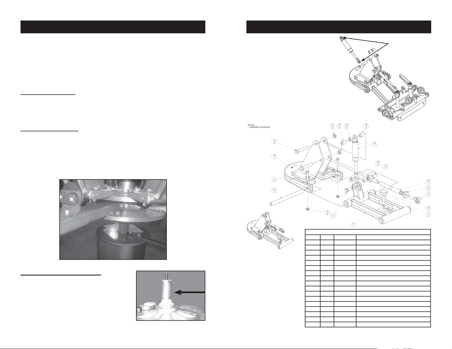
ITEM QTY PART # DESCRIPTION
1 2 10702 BOLT 1/4-20x1-1/2 ZPS
2 2 17111 Nut Hex 0420 NC ZP
3 1 18382 O-RING
4 1 29991 ROD END 3/8x3/8-24 RH
5 1 30007 ROD END 3/8x3/8-24 LH
6 2 47753 NUT HEX JAM 3/8-16 NC ZP
7 1 69302 SCREW MCH 3/8-16x1 FHSL
8 1 86017 KNOB, 5/16-18 CLAMPING
9 2 86850 BOLT 3/8-16 x 2-1/4
10 1 89326 SPRING, 150# GAS
11 1 1010600 ASSY, H-ARM
12 1 1010610 ASSY, PRINT HEAD BRACKET
13 2 1011032 BUSHING, GAS SPRING
14 1 1011033 SHAFT, H-ARM PIVOT
15 2 1011080 SPACER, GAS SPRING UPPER
16 2 1152004 SPACER, ROD END
17 1 1157002 ADJUSTMENT LOCK NUT
Fig 2
2
18 1 1157003 TUBE, KNURLED ADJUSTMENT
15
Page 3

GAS SPRING REPLACEMENT
PRINTER ASSEMBLY
PREMIER PRINTER GAS SPRING REPLACEMENT
Review pages Premier Printer exploded views and part identifi cation before
beginning. Drawings can be obtained though the manufacturer. Call tech
support 800-835-0606.
TOOLS REQUIRED
A. 9/16” box wrench
B. 9/16” socket & ratchet
C. Standard screwdriver
STEPS:
Rotate printhead wheel so that the printhead with the worn gas spring 1.
is centered between two shirtboard print stations.
Remove the shirtboards on both sides to allow for more work space 2.
while you change the worn gas spring.
Raise H-Arm to its most upright position (Fig. 38).3.
Fig. 38
(2) Spacers
H-Arm
Bolt
& Nut
NOTE: Make sure the bearing is seated evenly in the bearing race on the
bottom of the printwheel assembly such that wheel assembly turns
freely. 2 people required (Fig 3).
Fig 3
Place the tapered end of the bearing into the top race 4.
of the printwheel assembly and hand tighten the cap
on screw until snug. The cap on screw can then be
tightened an additional ¼ turn by inserting a rod into
the hole in the top of the bearing cap. (Fig 4)
Fig 4
SHIRTBOARD POSITION
Holding the bearing cap in place, tighten the nut fi rmly on the top of 5.
the spindle assembly.
NOTE: Spin and gently rock both upper and lower printwheels to assure
bearings are seated properly (Fig 5).
Remove bolt and Nut from top of 4.
gas spring with 9/16” box wrench
on one side and 9/16” socket
wrench on the other.
Remove (2) Spacers and (1) 5.
Bushing and retain for use with
new gas spring.
Once the top of gas spring has 6.
been released lower the H-Arm
to the lowest position and turn the
inclination link until the lower gas
spring pin is exposed out past the
printhead tower. (Fig. 39)
Take out fl athead screw.7.
(Fig. 39)
14
Flathead
screw
Inclination Link
Fig. 39
Fig 5
Attach shirtboards on the print arms, fl at
side in, push the shirtboard to the back
until they rest just under the print head and
tighten them using the knobs located on
the side FIRST. T ighten the bottom knob
second on the shirtboard clamps (Fig 6).
Fig 6
3
Page 4

PRINTER ASSEMBLY
JACKET HOLD DOWN SET-UP
REGISTRATION GUIDE ALIGNMENT
Lower 1. all print heads (Fig. 7). Tighten the (2) bolts (Fig. 8) that secure
the registration guide bracket to the arm.
Print Heads Down
Fig. 7
NOTE: This procedure must be done to ensure all print heads will register
for printing.
Two Bolts
Fig. 8
BRAKE WHEEL ADJUSTMENT
The brake wheel is mounted so as to allow the wheel to be raised or 1.
lowered to provide the braking action desired.
Loosen the retaining bolt and align brake wheel under a print arm.2.
Insert a Phillips screwdriver into the hole on the brake wheel shaft. 3.
(Fig. 9)
Raise or lower the brake wheel by moving the screwdriver to the desired 4.
brake resistance (Fig. 9).
1. Remove shirtboard and install the
jacket hold down board onto the
arm. Place the off-contact compensation cap over bolt head (Fig. 33).
NOTE: This cap compensates for the
height increase of the jacket
board over a standard board.
Fig. 33
2. Adjust the rubber grip blades so that
they are parallel with the edge of
the board. Gap adjustment will vary
depending on the jacket and liner
thickness. (Fig. 34)
Fig. 34
3. Center jacket over platen (Fig. 35)
with latch protruding.
NOTE: On small or youth size jackets, it
may be necessary to unzip the
jacket front fi rst.
Fig. 35
4. Lower the holddown into position
(Fig. 36) and lock the toggle latch.
Check the jacket position to ensure it
is centered properly before printing.
Reposition grip (step 2) as necessary.
Fig. 9
Tighten the retaining bolt and check the braking action. 5.
Re-adjust if needed.6.
4
5. Lock the toggle latch so the frame
will not tend to creep up (Fig. 37).
NOTE: It is wise to “pre-flash” each
jacket before the fi rst print is
made to prevent shrinking of
the jacket, which can cause
registration problems when doing multi-color prints.
13
Fig 36
Fig. 37
Page 5

KING PIN SYSTEM
Expose each screen one at a time (Fig. 31), washout, dry and prep for
printing.
Step 3: Align the docking hole in the exposed frame with the PIN on mounting plate bolted to the printer. (Fig. 32) Lock the screen in position with
back or side clamps on each print head. Add your ink to each screen and
proof the print. Check the print itself and the registration marks for correct
alignment and visual
Fig. 27 Fig. 28
SET PRINTHEAD
NOTICE: Failing to properly set up
printhead level will not allow
print to be registered.
YOUR HIX PRESS MUST BE REGISTERED ON CONTACT!
(Meaning the exposed screen is touching the shirtboard. )
Front to rear adjustment. Insert Screen into screen clamp (see 1.
page 6) and adjust the screen tilt adjustment (see page 9).
Adjust so that the screen is parallel with the shirt board front to back,
and make sure your screen sits totally fl at on the shirtboard. Or the
screen will slip when you tighten the ratchet handles. (See handles on
page 7 Fig. 13)
Left to right/ Parallel adjustment.2. Be sure the back screen clamp (or
cross tube holding side clamps) is level and parallel in relationship to
the shirtboard. (Left to right on the shirtboard) There are two bolts that
secure the back clamp (or crosstube) to the lower registration plate.
Slightly loosen nuts holding these bolts. The left side of the back
clamp (or crosstube) is oversized which allows you to move the clamp
(or crosstube) to align the screen parallel to the shirt board. Adjust to
parallel and tighten.
NOTE: If not level after tightening repeat steps 1 and 2 above.
WARNING: Failing to level this section of the printer will cause an un-even
contact from the left to the right or front to rear. This may
will cause the screen to “slip” or move when you tighten the
registration ratchet handles.
Fig. 29 Fig. 30
exposure plate docking pin
Fig. 31 Fig. 32
mounting plate docking pin
12
Not to scale
Back clamp
Screen not level
Screen Level
Front to Rear
Shirtboard
Cross tube that holds side clamps
Left to Right
Shirtboard
5
Page 6

SCREEN INSTALL. & ADJUST.
PREPRESS & REGISTRATION
FOR BACK CLAMPS: (FIG. 10)
1. Loosen both black knobs on the back clamp and center the screen 1.
in the clamp making sure the screen is all the way inside the clamp.
2. Tighten the black knobs so that they securely grip the screen.2.
FOR SIDE CLAMPS: (FIG. 11 AND 12)
(If the side clamp is not attached see Fig 12)
Loosen the two black adjustment knobs on each side clamp wide 1.
enough to accept the screen.
Loosen the angled back knob on the back of each side clamp and 2.
move clamps far enough apart on the cross tube so that the screen
will fi t into the clamps.
Insert the screen into the side clamps and press clamps inward so that 3.
they are against the sides of the screen frame and centered over the
shirtboard. Center on the crosstube.
Gently tighten the angled knobs on the cross tube.4.
NOTE: Do not overtighten.
Tighten the two black knobs on each side clamp to securely grip the 5.
screen.
Back Clamp Fig. 10
Slide this
side over
cross tube.
Fig. 12
NOTE: The bolt securing the left hand side of the cross tube is in an over-
sized hole allowing for adjustment if a screen is slightly warped
or twisted. Likewise, printers confi gured with the back clamp fea-
ture a similar slotted hole which exists to allow for leveling of the
screen.
Remember if you modify this adjustment for a warped screen, to
reset printhead for fl at screen (see page 5)
Loosen the nuts on the cross tube or the back clamp. Adjust up or
down so that the screen is parallel (right to left) to the shirt board.
6
Side Clamp Fig. 11
Allen screws
registration
take-up nut
Loosen the two Allen screws on the registration take-up nut.1.
Loosen the 1/4-20x0.750 bolt on the opposite side of main pivot 2.
pin as the registration take-up nut.
Turn the registration take-up nut clockwise to tighten the 3.
space and remove any play. BE CAREFUL NOT TO OVER
TIGHTEN.
Tighten the two Allen screws and bolt from steps 1 and 2.4.
H-Arm
bolt
KING PIN SYSTEM
The HIX King PIN™ registration system lets you go from art, to exposure,
to printer in 3 simple and very fast steps. This kit includes a precision hole
punching device, exposure plate and a pin mounting plate for each of your
print heads.
KING PIN™ REGISTRATION SYSTEM:
The King PIN™ system was designed to save additional set up time during
the pre press process. From fi lm positive alignment, to screen exposure,
to print set up and registration, the innovative King PIN™ system is very
easy to use.
Combine the King PIN™ system with the HIX Micro-registration print head
and your registration needs are covered. The King PIN™ system quickly
attaches to all HIX printers.
Step 1: After generating fi lm positives or vellums, line them up and tape
together (in registration). (Fig. 27)
Insert all and center the taped positives into the hole punching device and
punch holes. (Fig. 28) Remove the tape from the fi lm positives and attach
each individual positive to the King PIN™ exposure plate pins. (Fig. 29
and Fig. 30 )
Step 2: Position the exposure plate with the positive attached on your
exposure unit. Take your unexposed screen and position the frame (side
with the slotted hole) snug into the docking position PIN on the exposure
plate. (Fig. 30)
11
Page 7

PREPRESS & REGISTRATION
PREPRESS & REGISTRATION
If your clamps are too loose when you begin the adjustments (Fig.
23) your screen may jump out of registration during fi nal clamping.
(See page 5)
ratchet handles
registration
knobs
Fig. 23
Before proceeding to the next print head alignment, measure the dis-9.
tance between the end of the shirt board clamp and the registration
guide on the print arm. This distance should be the same for all the
other shirt boards in the setup process. (Fig. 24) Adjust if necessary
see shirtboard position pg. 3
NOTICE: Before printing follow these steps below.
The fi rst step involves setting all 1.
micro register heads to a neutral
position. This can be done by
loosening the ratchet handles approximately a 1/4 turn (Fig. 13) and
then turning the three registration
knobs (Fig. 14) until the arrow tab
points (Fig. 15) to the center of the
inscribed cross hairs.
Perform this adjustment on every
print head that takes a screen.
registration
knobs
Fig. 14
ratchet handles
Fig. 13
Fig. 24
NOTE: Over time the bushings (Fig. 25) between the micro-registration and
the H-Arm could become worn and create play in the print head.
This play can cause prints to fall out of registration. An adjustment
to the registration take-up nut (Fig. 26) on the micro-registration
will need to be made.
Fig. 25
Fig. 26
H-Arm
10
Fig. 15
7
Page 8

PREPRESS & REGISTRATION
PREPRESS & REGISTRATION
Center, level, and tape your art/2.
fi lm positive (normally the black
or trap) on one shirt board using
a T-Square and a ruler. Roughly
center or position to desired location. Make sure all printable
images lie within the boundary of the shirtboard. (Fig. 16)
Then register your screens to
the film positive (see page 9).
(film positive- Any artwork on
a clear fi lm that can be used to
expose a screen.
Optionally, if you do not have a positive or vellum; you can spray tack 3.
adhesive on the shirt board, then load a shirt or pellon onto the board.
Then “print” the black/darkest color or keyline positive directly onto the
shirt or pellon. Cure, then register your screens to this print (see page
9). (keyline positive- the outline that traps all other color separation
positives. pellon- test print material, so to not ruin usable material.)
NOTE: Slight adjustments to the shirtboard to improve alignment may be
necessary.
To adjust the shirtboard:4. (Fig.
17) Loosen the shirt board and
position so that it lines up with the
screen frame when it is lowered
into the horizontal position.
REMEMBER to tighten the side knob
fi rst and then the bottom/larger knob.
Lower the screen onto the shirt 5.
board with the taped artwork.
Loosen the screen clamps on back 6.
clamp models or angled back
knob on side clamp presses and
center the screens side to side if
needed.
Note: Keep
in mind you
still want the
screen to fit
tight against
the back of the
screen clamps
to improve support. (Fig. 18)
side to side
8
Fig. 16
Fig. 17
Fig. 18
Lower your screen all the way down to the shirt board. You may have 7.
to use the off contact adjustor (Fig. 19) and your screen leveler (Fig.
20) to achieve front to rear “contact” with the shirt board. Now slightly
loosen the ratchet handles. Y ou should be able to notice the movement
of the screen after adjusting the three adjustment nuts. (Fig. 14)
off contact adjustor screen leveler
Fig. 19
ShirtboardShirtboard
If not parallel left to right see page 5, step #2.
Looking through the screen (Fig. 21) use the adjustment knobs. (Fig. 22-23)8.
Fig. 21 Fig. 22
Once you have achieve perfect lineup with the screen and art, hold the
screen down with your hand and then working back and forth, gently
snug up the ratchet handles (Fig. 23) until the screen is fi rmly locked
in place. Recheck your registration then use the off contact and the
screen leveling adjustment to raise the screen approximately 1/16” off
the shirtboard surface.
NOTE: If your ratchet handles are too tight you may cause damage to the
adjustment nuts by forcing them. (Fig. 23)
9
Fig. 20
 Loading...