

Page 1
WARRANTY
HIX will automatically register the equipment on the date it was shipped to you or your distributor.
If the equipment was not purchased directly from HIX, but through a distributor (either domestic
or foreign), please keep a copy of their sales invoice showing the serial number and date it was
sold/shipped to you with this warranty. In this case, we will use the distributor’s invoice date as the
beginning warranty date. STAPLE A COPY OF YOUR RECEIPT TO THIS W ARRANTY and keep
in a safe place to provide verifi cation of your warranty should a problem occur. Thank you.
Please fi ll in the following information and attach a copy of your receipt for your records.
Date Purchased: From:
Model #: Serial #:
This warranty applies to equipment manufactured by the HIX Corporation (HIX), Pittsburg, Kansas, U.S.A. HIX warrants to the original purchaser, its Ovens and Dryers, Heat Transfer Presses,
Mug Presses, Mug Glazer, Retensionable Screen Frames, Textile Printers, Spot Heaters, and Exposure Units against defects in workmanship and material, except for wear and tear for a period of
“One Y ear” from the date of purchase. HIX warrants its Accessories, Reten Splines/Hardware/Tool
Kit, and Shuttle for a period of 90 days from the date of purchase. Thermatrol and doughXpress
products are covered under separate warranty.
In the event of a defect, HIX, at its option, will repair, replace or substitute the defective item at
no cost during this period subject to the limitations of insurance and shipping costs stated below.
In the case of heat transfer presses (except the Hobby Lite), HIX warrants the heat casting for
the “Life” of the machine for the original purchaser. If a part becomes obsolete at the time for repair ,
and/or cannot be reasonably substituted for, HIX will credit, at half the then current list price or last
recorded price, only that part toward a new machine or any product HIX offers. This credit offer
shall be the sole responsibility of the HIX Corporation in the event of an obsolete part.
This warranty does not cover belts, pads, mug wraps, canvas, rubber blankets, bulbs, glass, rod
ends, turn buckles on printers or damages due to accident, misuse/abuse, alterations or damage
due to neglect, shipping or lack of proper lubrication or maintenance. HIX shall not be responsible
for repairs or alterations made by any person without the prior written authorization by HIX. This
warranty is the sole and exclusive warranty of HIX and no person, agent, distributor, or dealer of
HIX is authorized to change, amend or modify the terms set forth herein, in whole or in part.
In the case of a problem with the equipment identifi ed herein, HIX Corporation should be con-
tacted during regular business hours to discuss the problem and verify an existing warranty. HIX
personnel will assist the customer to correct any problems which can be corrected through operation
or maintenance instructions, simple mechanical adjustments, or replacement of parts. In the event
the problem cannot be corrected by phone, and upon the issuance of a return authorization by
HIX, the equipment shall be returned to HIX or an authorized service representative. All insurance,
packaging and shipment/freight costs are solely the responsibility of the customer, and not that
of HIX, and HIX shall not be responsible for improper packaging, handling or damage in transit.
Contact HIX customer service for complete return authorization information. Correct shipping boxes
are available from HIX.
This expressed warranty is given in lieu of any and all other warranties, whether expressed or
implied, including but not limited to those of merchantability and fi tness for a particular purpose,
and constitutes the only warranty made by HIX Corporation.
In no event shall HIX’s liability for breach of warranty extend beyond the obligation to repair or
replace the nonconforming goods. HIX shall not be liable for any other damages, either incidental
or consequential, or the action as brought in contract, negligence or otherwise.
This warranty gives you specifi c legal rights and you may also have other rights which vary from
state to state.
Manufacturers of the Finest Quality Textile and Graphics Screen Printing and Heat Transfer Equipment
1201 E. 27th Terrace • Pittsburg, KS 66762 • U.S.A.
Web site: www.hixcorp.com • Phone: (800) 835-0606 • Fax: 620-231-1598
E-Mail: customerservice@hixcorp.com • E-Mail: sales@hixcorp.com
(Effective September 1, 2010)
8
©2010 HIX Corp.
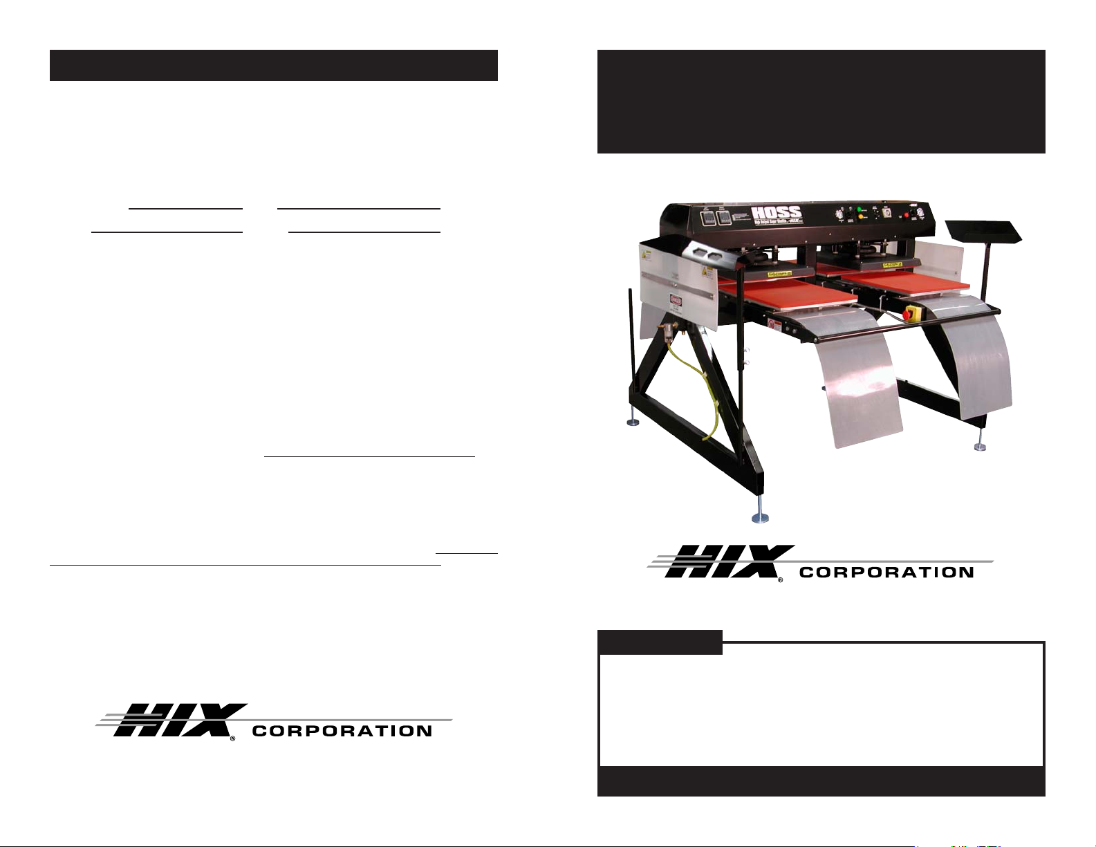
HOSS
High Output Super Shuttle
OWNER’S MANUAL
HOSS
For Customer Service, Call 1-800-835-0606
or Visit www.hixcorp.com
CONTENTS
Receiving and Installation 2
Operation 3-5
Transfer Application 5-6
Troubleshooting 7
Warranty 8
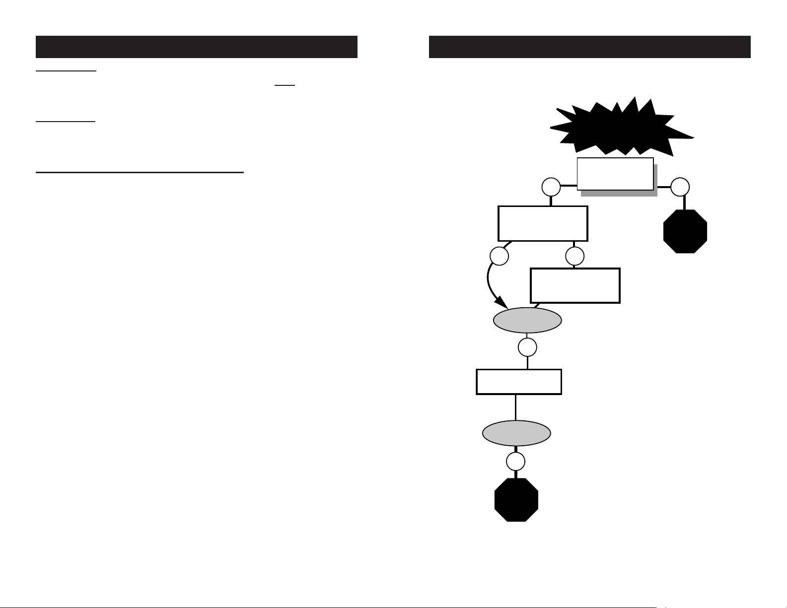
BEFORE warranty repair you MUST get Prior Authorization:
47469 RV C_101310
Page 2
RECEIVING & INSTALLATION
Problem solved?
NO
Problem solved?
NO
Machine will
not stay closed
Can the air pressure
be set at the
desired level?
NO
YES
Call
Technical
Service
YES
NO
NO
Does upper casting
clamp when machine
cycle is started?
Check the timer function
switches for proper setting.
Must be on Mode "A".
Check micro switch
adjustment
Call
Technical
Service
∗
TROUBLESHOOTING
INSPECTION
DO NOT SIGN FOR THE SHIPMENT IF YOU SEE ANY CRA TE DAM-
AGE. Inspect your machine for hidden shipping damage. Contact the
delivery company immediately, should you fi nd damage.
UNPACKING
Remember to save all packing materials. Y ou may need these for ship-
ping your machine in the future. After disassembling the crate save the
skid and side boards.
SETUP AND INSTALLATION INSTRUCTIONS
Remove unit from shipping crate and base. Do not use a fork lift under 1.
the machine to remove from shipping skid to avoid damage to the air
cylinders. Recomended: Use at least 4 or more people capable of lifting
150 lbs. each to lift at each corner and the bars, or use a forklift with
extensions long enough to extend past the width of the HOSS’s legs.
Place forks under horizontal bottom leg support. Lift with caution.
Place unit in desired operating location.2.
Level the machine pads on each corner so that the machine sits in 3.
a level position and at the desired operation height (Check that the
machine is level with a carpenters level).
Supply 100 - 1 15 PSI (7-8 bar) air supply to machine with 3/8” (10mm) 4.
diameter hose, minimum. Air requirements 8 CFM (226 L) per minute
at 100 PSI . Air inlet is located on the left side frame support leg (when
facing the control panel).
NOTE: It is strongly recommended that an external air fi lter and water trap
be installed at the machine’s air inlet connection. Compressed air is
dirty. It has ‘stuff’, primarily moisture, residues from oil and smoke and
whatever else is in the air. Compressors or ‘shop air’ may have fi ltered
air and/or an “AIR DRYER” after the compressor . IF your air is not fi ltered
and dried, YOU MUST FILTER THE AIR and REMOVE THE WATER
AND ‘STUFF’ FROM THE AIR, before putting it in most air operated
machines, including our press. There are small valves and ports that can
become blocked from moisture and residue in compressed air, causing
your press to malfunction. An external air fi lter and water trap must be
installed at the machine’s air inlet connection, if your air is not fi ltered.
Damage to the machine’s internal air operated components can occur
that will not be covered under warranty. Combination air fi lter/water
traps are available at any major hardware store or may be purchased
directly from HIX (part #71145).
Supply voltage and current per wiring diagram.5.
Note this is an industrial piece of equipment with an automatic cycle. 6.
All safety guards must be left in place at all times when the machine is
operating. Operating without the guards will present access to pinch
and crush points and thus pose dangerous exposure to the operators.
2
WARNING: Before making repairs, be sure on/off
switch is off and machine is unplugged!
*Customer Service Tech Sheets are available for this step.
Visit www .hixcorp.com to print or call 620-231-8568 and we
will send you one. Parts ordering is available on-line.
7
Page 3

TRANSFER APPLICATION
RECEIVING & INSTALLATION
FIRST, THE BASICS:
Be sure to set the heat transfer machine to the transfer manufacturer’s 1.
recommended Temperature, Time and Pressure settings. If you don’t
have these specifi cations, contact your transfer supplier for this infor-
mation and any other special application instructions as many of the
new “High Tech” transfers require signifi cantly different settings and/or
application techniques than those from years past.
When you start up your press for the fi rst time each day, preheat the 2.
pad for a minute. If the press has sat for 3-5 minutes without use, be
sure to “preheat” the pad for 10-15 seconds before loading the shirt or
making the fi rst transfer.
Be sure the T -shirt fabric is void of any moisture which can reduce the 3.
chance of a successful transfer.
With all of the above recommendations, try making a transfer. 4.
If successful, great! You are on your way to making some serious 5.
money with your transfer machine!
If you have an area that isn’t transferring completely or as you would 6.
like it to, follow these steps to determine the problem.
Try increasing the pressure on the machine by 10-20% •
Recheck your temperature required and the press readout. Y ou may •
want to increase the temperature 10 degrees.
Try increasing the application time by 2-4 seconds •
If after trying these things there is still a “specifi c” area (say over in •
one corner of the transfer) that isn’t coming out as you would like
it to, then try the same type transfer on a scrap shirt but rotate the
transfer 180 degrees (changing the failure location) If after doing
this the problem area is in the same physical location on the machine, then you probably have a problem with the pad or possibly a
warped platen if the machine has ever overheated severely . On the
other hand if the transfer failed in the same area on the transfer (after changing the location of where the problem had previously been
occurring), then you most likely have a problem with the transfer or
it’s application settings (Temperature, Time or Pressure) and you
should contact your transfer supplier to discuss the problem.
Following these basic guidelines can help you be more successful with
each and every transfer!
The HOSS should never bE left unattended while cycling. Extreme
caution and awareness should be exercised when operating this
machine. Children should not be allowed access to the machine.
Heated platens can cause severe burns. Do Not set objects on the
machine. To avoid electrical shock use only in dry locations. Service
only by qualifi ed technicians.
OPERATION
Raise the lever on the operator switch marked “Circuit Breaker” located 1.
on the front of the control panel to the “ON” position.
Ensure that all Emergency Stop (E-Stop) operator buttons are released. 2.
Two E-stops are located on each machine in the event that the machine needs to be stopped for any reason. If either of the buttons are
pressed in, they will latch and all machine operation will halt. To reset
the E-stop, gently push the operator button in and “Twist” the button in
a “Clockwise” direction and the button will pop back out to its’ normal
operating position.
Press the “Yellow” operator button on the front of the control panel 3.
marked “Power On” to activate power to the unit. If the lower platens
are not in their “Base” or “Home” position, they will move to the required
starting location.
At this time you may adjust the following settings as required by the par-4.
ticular type of transfer you are using and it’s specifi c requirements.
Heat Platen Temperature - This may be adjusted for each station •
with the digital temperature controller located on the control panel
side of the machine.
DIGITAL TEMPERATURE CONTROL
Upper display shows
current value of process
(platen) temperature.
Lower display
shows setpoint
Not functional.
Will decrease
setpoint (SP)
when “SP” is
displayed.
Will increase setpoint (SP)
when “SP” is displayed.
temperature.
Pressing this function button
once will allow “SP” to be displayed enabling the operator to
change the setpoint by pressing the “up” and “down” buttons
located below. Pressing once
again will return the displays to
their normal operating mode.
6
3
Page 4

OPERATION
OPERATION
Clamping Pressure - This pressure is pre-set at the factory to •
90psi(6.2bar) and can be adjusted for each station by adjusting the air
regulators located on the front of the control panel. These regulators
and the corresponding gauges only operate while the heat platens
are down (pressing). At all other times, the gauges will read zero
pressure. See Instruction #8 for setting instructions.
Clamping Time - This may be adjusted by adjusting the dwell time •
on the “Timer” located on the front control panel.
Once you have all the above parameter adjustments set to the required 5.
setting as suggested by the transfer manufacturer, you can proceed to
the next step. Note it will take approximately 20 minutes for the heat
platens to come up to operating temperature. This is normal.
Before continuing, note there are two ways to “Stop” the machine.6.
Emergency Stops • - Pressing to activate either of the two “Emer-
gency stops” (one Red/Yellow colored Mushroom operator located
on each side of the machine between the shuttle platen stations), will
immediately stop or halt all operation of the machine. If the machine
is in the middle of a pressing cycle, the heat platens will release and
return to the “open” position. These stops should only be used in
a situation where Emergency Stop is ever activated, you will need
to again press the “Yellow” operator marked “Power On” to regain
operation of the machine.
NOTE: An E- Stop must be reset. (See #2 on page 2).
Cycle Stop • - The “Red” operator button marked “Cycle Stop” located
on the control panel front will interrupt the machine cycle. When this
operator is pressed, the heat platens will open after fi nishing their
timed press cycle.
NOTE: This is the normal way to shut down operation of the HOSS.
Now that you know how to stop the machine, you are ready to start the 7.
automatic cycle. T o begin the cycle, press the “Green” operator button
“Start Cycle”. Once pressed the lower platens will begin moving and
the pressing cycle will start once a lower platen is under a heat head.
At the end of the elapsed time as set on the timer, the heat heads will
release and the platens will “Shuttle” to the opposite position. When
you want it to stop (unless an emergency), the best way to interrupt the
cycle is to press the “Cycle Stop” operators. If “cycles stop” is pressed,
machine cycle can be continued by pressing Green “Start Cycle Operator Button.” If there is an emergency, one of the Emergency Stop
operators can be activated.
While the heat platens are warming, the clamping pressure can be 8.
set. Start the cycle by pressing the green “Cycle Start” operator button. When the heat platens begin to press, the air gauges will indicate
the clamping pressure. To adjust the pressure, pull gently out on the
air regulator knob and turn it until the desired pressure is indicated,
4
turning “Clockwise” to increase pressure and “Counter-Clockwise” to
decrease pressure. THE MAXIMUM ALLOWABLE PRESSURE IS
90PSI(6.2bars)!!
It is recommended to allow the machine to cycle for a few minutes after 9.
the heat platens have reached the desired operating temperature before
starting to apply transfers. This will allow the lower platens to warm up
properly and will provide a better quality transfer.
NOTE: Allow to set 5 minutes at operating temperature.
When you have fi nished for the day and have removed all products 10.
from the HOSS, push the “Cycle Stop” button. After the HOSS stops
cycling switch the “Circuit Breaker” to the “Off” position.
This is an industrial piece of equipment with an automatic cycle. All 11.
safety guards must be left in place at all times when the machine is
operating. Operating without the guards will present access to pinch
and crush points and thus pose dangerous exposure to the operators.
The HOSS should never be left unattended while cycling. Extreme caution and awareness should be exercised when operating this machine.
Children should not be allowed access to the machine.
TRANSFER APPLICATION
The HOSS is ideal for Heavy High Volume applications. The HOSS was
designed for two people to operate for max production. One person on
each side.
Align garment on the lower platen and smooth out the wrinkles.1.
Set the timer to the desired time setting. 2. Always consult your specifi c
transfer recommendations. Typical setting are: Cold Peel - 350°F
(177°C), 15 seconds and Hot Split - 375°F (190°C), 10 - 12 seconds.
Position the transfer, then press the cycle start switch to start the cycle 3.
operation. At the end of the pre-set time, the platens will cycle, and
provide a lower with shirt and hot transfer to you.
Continuously peel the paper off the transfer away from your garment. 4.
Successful transfer work depends on the correct balance of time,
temperature and pressure. The type and thickness of the material
and the kind of transfer being used will determine what settings are
necessary.
If a hot peel/split transfer is being applied, immediately peel the paper after
the machine has opened. DO NOT allow the transfer to cool. If a cold peel
transfer is being applied, rub the transfer with a chalk board eraser or cloth
and allow to cool for 5 - 10 seconds before removing the release paper.
When you fail to make a successful transfer you can wonder, “Is it
the machine’s fault, or the transfer, wrong settings or what”?
5
 Loading...